JP6359090B2 - Equipment and method for separating labels and other substances from plastic bottles - Google Patents
Equipment and method for separating labels and other substances from plastic bottles Download PDFInfo
- Publication number
- JP6359090B2 JP6359090B2 JP2016514443A JP2016514443A JP6359090B2 JP 6359090 B2 JP6359090 B2 JP 6359090B2 JP 2016514443 A JP2016514443 A JP 2016514443A JP 2016514443 A JP2016514443 A JP 2016514443A JP 6359090 B2 JP6359090 B2 JP 6359090B2
- Authority
- JP
- Japan
- Prior art keywords
- conduit
- stage
- product
- bottles
- fragment
- Prior art date
- Legal status (The legal status is an assumption and is not a legal conclusion. Google has not performed a legal analysis and makes no representation as to the accuracy of the status listed.)
- Expired - Fee Related
Links
Images


Classifications
-
- B—PERFORMING OPERATIONS; TRANSPORTING
- B29—WORKING OF PLASTICS; WORKING OF SUBSTANCES IN A PLASTIC STATE IN GENERAL
- B29B—PREPARATION OR PRETREATMENT OF THE MATERIAL TO BE SHAPED; MAKING GRANULES OR PREFORMS; RECOVERY OF PLASTICS OR OTHER CONSTITUENTS OF WASTE MATERIAL CONTAINING PLASTICS
- B29B17/00—Recovery of plastics or other constituents of waste material containing plastics
- B29B17/02—Separating plastics from other materials
-
- B—PERFORMING OPERATIONS; TRANSPORTING
- B07—SEPARATING SOLIDS FROM SOLIDS; SORTING
- B07B—SEPARATING SOLIDS FROM SOLIDS BY SIEVING, SCREENING, SIFTING OR BY USING GAS CURRENTS; SEPARATING BY OTHER DRY METHODS APPLICABLE TO BULK MATERIAL, e.g. LOOSE ARTICLES FIT TO BE HANDLED LIKE BULK MATERIAL
- B07B11/00—Arrangement of accessories in apparatus for separating solids from solids using gas currents
- B07B11/04—Control arrangements
-
- B—PERFORMING OPERATIONS; TRANSPORTING
- B07—SEPARATING SOLIDS FROM SOLIDS; SORTING
- B07B—SEPARATING SOLIDS FROM SOLIDS BY SIEVING, SCREENING, SIFTING OR BY USING GAS CURRENTS; SEPARATING BY OTHER DRY METHODS APPLICABLE TO BULK MATERIAL, e.g. LOOSE ARTICLES FIT TO BE HANDLED LIKE BULK MATERIAL
- B07B9/00—Combinations of apparatus for screening or sifting or for separating solids from solids using gas currents; General arrangement of plant, e.g. flow sheets
-
- B—PERFORMING OPERATIONS; TRANSPORTING
- B07—SEPARATING SOLIDS FROM SOLIDS; SORTING
- B07B—SEPARATING SOLIDS FROM SOLIDS BY SIEVING, SCREENING, SIFTING OR BY USING GAS CURRENTS; SEPARATING BY OTHER DRY METHODS APPLICABLE TO BULK MATERIAL, e.g. LOOSE ARTICLES FIT TO BE HANDLED LIKE BULK MATERIAL
- B07B7/00—Selective separation of solid materials carried by, or dispersed in, gas currents
- B07B7/01—Selective separation of solid materials carried by, or dispersed in, gas currents using gravity
-
- B—PERFORMING OPERATIONS; TRANSPORTING
- B29—WORKING OF PLASTICS; WORKING OF SUBSTANCES IN A PLASTIC STATE IN GENERAL
- B29B—PREPARATION OR PRETREATMENT OF THE MATERIAL TO BE SHAPED; MAKING GRANULES OR PREFORMS; RECOVERY OF PLASTICS OR OTHER CONSTITUENTS OF WASTE MATERIAL CONTAINING PLASTICS
- B29B17/00—Recovery of plastics or other constituents of waste material containing plastics
- B29B17/02—Separating plastics from other materials
- B29B2017/0203—Separating plastics from plastics
-
- B—PERFORMING OPERATIONS; TRANSPORTING
- B29—WORKING OF PLASTICS; WORKING OF SUBSTANCES IN A PLASTIC STATE IN GENERAL
- B29B—PREPARATION OR PRETREATMENT OF THE MATERIAL TO BE SHAPED; MAKING GRANULES OR PREFORMS; RECOVERY OF PLASTICS OR OTHER CONSTITUENTS OF WASTE MATERIAL CONTAINING PLASTICS
- B29B17/00—Recovery of plastics or other constituents of waste material containing plastics
- B29B17/02—Separating plastics from other materials
- B29B2017/0213—Specific separating techniques
- B29B2017/0217—Mechanical separating techniques; devices therefor
- B29B2017/0234—Mechanical separating techniques; devices therefor using gravity, e.g. separating by weight differences in a wind sifter
-
- B—PERFORMING OPERATIONS; TRANSPORTING
- B29—WORKING OF PLASTICS; WORKING OF SUBSTANCES IN A PLASTIC STATE IN GENERAL
- B29B—PREPARATION OR PRETREATMENT OF THE MATERIAL TO BE SHAPED; MAKING GRANULES OR PREFORMS; RECOVERY OF PLASTICS OR OTHER CONSTITUENTS OF WASTE MATERIAL CONTAINING PLASTICS
- B29B17/00—Recovery of plastics or other constituents of waste material containing plastics
- B29B17/02—Separating plastics from other materials
- B29B2017/0213—Specific separating techniques
- B29B2017/0217—Mechanical separating techniques; devices therefor
- B29B2017/0237—Mechanical separating techniques; devices therefor using density difference
- B29B2017/0241—Mechanical separating techniques; devices therefor using density difference in gas, e.g. air flow
-
- B—PERFORMING OPERATIONS; TRANSPORTING
- B29—WORKING OF PLASTICS; WORKING OF SUBSTANCES IN A PLASTIC STATE IN GENERAL
- B29K—INDEXING SCHEME ASSOCIATED WITH SUBCLASSES B29B, B29C OR B29D, RELATING TO MOULDING MATERIALS OR TO MATERIALS FOR MOULDS, REINFORCEMENTS, FILLERS OR PREFORMED PARTS, e.g. INSERTS
- B29K2067/00—Use of polyesters or derivatives thereof, as moulding material
- B29K2067/003—PET, i.e. poylethylene terephthalate
-
- B—PERFORMING OPERATIONS; TRANSPORTING
- B29—WORKING OF PLASTICS; WORKING OF SUBSTANCES IN A PLASTIC STATE IN GENERAL
- B29L—INDEXING SCHEME ASSOCIATED WITH SUBCLASS B29C, RELATING TO PARTICULAR ARTICLES
- B29L2031/00—Other particular articles
- B29L2031/56—Stoppers or lids for bottles, jars, or the like, e.g. closures
- B29L2031/565—Stoppers or lids for bottles, jars, or the like, e.g. closures for containers
-
- B—PERFORMING OPERATIONS; TRANSPORTING
- B29—WORKING OF PLASTICS; WORKING OF SUBSTANCES IN A PLASTIC STATE IN GENERAL
- B29L—INDEXING SCHEME ASSOCIATED WITH SUBCLASS B29C, RELATING TO PARTICULAR ARTICLES
- B29L2031/00—Other particular articles
- B29L2031/712—Containers; Packaging elements or accessories, Packages
- B29L2031/7158—Bottles
-
- B—PERFORMING OPERATIONS; TRANSPORTING
- B29—WORKING OF PLASTICS; WORKING OF SUBSTANCES IN A PLASTIC STATE IN GENERAL
- B29L—INDEXING SCHEME ASSOCIATED WITH SUBCLASS B29C, RELATING TO PARTICULAR ARTICLES
- B29L2031/00—Other particular articles
- B29L2031/744—Labels, badges, e.g. marker sleeves
-
- Y—GENERAL TAGGING OF NEW TECHNOLOGICAL DEVELOPMENTS; GENERAL TAGGING OF CROSS-SECTIONAL TECHNOLOGIES SPANNING OVER SEVERAL SECTIONS OF THE IPC; TECHNICAL SUBJECTS COVERED BY FORMER USPC CROSS-REFERENCE ART COLLECTIONS [XRACs] AND DIGESTS
- Y02—TECHNOLOGIES OR APPLICATIONS FOR MITIGATION OR ADAPTATION AGAINST CLIMATE CHANGE
- Y02W—CLIMATE CHANGE MITIGATION TECHNOLOGIES RELATED TO WASTEWATER TREATMENT OR WASTE MANAGEMENT
- Y02W30/00—Technologies for solid waste management
- Y02W30/50—Reuse, recycling or recovery technologies
- Y02W30/62—Plastics recycling; Rubber recycling
Landscapes
- Engineering & Computer Science (AREA)
- Environmental & Geological Engineering (AREA)
- Mechanical Engineering (AREA)
- Separation, Recovery Or Treatment Of Waste Materials Containing Plastics (AREA)
- Combined Means For Separation Of Solids (AREA)
- Processing And Handling Of Plastics And Other Materials For Molding In General (AREA)
Description
発明の背景
本発明は、プラスチックの取り扱いおよび再生の分野において、プラスチック製のボトル、特に、PET製のボトルからラベル、キャップおよびその他の汚染物質を分離するための一つの設備および一つの方法に関連する。
BACKGROUND OF THE INVENTION This invention relates to one facility and one method for separating labels, caps and other contaminants from plastic bottles, particularly PET bottles, in the field of plastic handling and recycling. To do.
先行技術
文献JP2011005848、KR20000019385およびWO2011/012113に開示されているように、プラスチック製の容器からラベル、キャップおよびその他の物体を除去するための装置が知られている。
Devices are known for removing labels, caps and other objects from plastic containers, as disclosed in the prior art documents JP 2011005848, KR20000019385 and WO2011 / 012113.
プラスチック、特に、PET製の使用済みの容器またはボトルの再利用のため、そのような容器またはボトルはまず、それら容器に付着している異物を除去するための予備洗浄工程が施され、そして、引き続く工程において、ラベルまたはその他の物体を取り除くため、一つの回転ドラム装置の中で処理されることが知られている。続いて、ボトルおよび容器は後続の破砕工程に移され、そこで、例えば、センチメートルレベルの、小さな寸法の断片に還元される。それらの断片は、最後に、汚染物質および/またはプラスチックの断片に付着したままの固体粒子を除去するために、さらなる洗浄工程が施される。 In order to reuse used containers or bottles made of plastic, in particular PET, such containers or bottles are first subjected to a pre-cleaning step to remove foreign matter adhering to the containers, and In subsequent steps, it is known to be processed in a single rotating drum device to remove labels or other objects. Subsequently, the bottles and containers are transferred to a subsequent crushing process where they are reduced to small sized pieces, for example on the centimeter level. The pieces are finally subjected to further washing steps to remove solid particles that remain attached to the contaminants and / or plastic pieces.
回転ドラム装置から離れ、そして破砕工程へと向かう容器やボトルは、しばしば、先に述べた装置が、それら容器から完全に除去し、取り去ってしまうことができないような破片やラベルまたはもっと言えばラベル全体または他の物体を伴う。その結果、続く破砕および洗浄工程において、容器およびボトルに加え、前述の物体並びにラベルおよび他の汚染物質は、それらが完全に除去されない場合、得られる再利用材料に影響を与え、またはその品質を落としてしまうことがある。もちろん、ある限界を超えて汚染残渣が存在すると、産業的に満足できない純度の回収プラスチックが得られることになる。一方、関連する処理コストを掛けて大量の洗浄水と化学添加物を使うこと、廃棄問題および水を加熱することに関連する莫大なエネルギー消費は、プロセスにおいて一般的な改善を得るために介入することが望ましいということにとっての限界および弱点である。したがって、ラベル、キャップおよび他の物体を、ボトルや容器からより効率的に分離することを可能にし、そして、同時に、断片化されたプラスチックを洗浄するための費用およびエネルギー、水および添加物を削減し、または、少なくとも、同じ費用且つ量の後者の利用によって、現在利用されている先行技術によるプロセスおよびシステムで得られる回収されたプラスチック材料の純度より大幅に向上させることを可能にする解決策を追い求める需要が依然として存在している。 Containers and bottles that leave the rotating drum unit and go to the crushing process often have debris or labels or, more specifically, labels that the previously mentioned devices cannot completely remove and remove from those containers. With whole or other objects. As a result, in subsequent crushing and cleaning processes, in addition to containers and bottles, the aforementioned objects, as well as labels and other contaminants can affect the reclaimed material obtained or their quality if they are not completely removed. It may drop. Of course, if there is a contamination residue exceeding a certain limit, a recovered plastic with an unsatisfactory industrial purity can be obtained. On the other hand, the use of large amounts of wash water and chemical additives at the associated processing costs, disposal problems and the enormous energy consumption associated with heating the water intervene to obtain general improvements in the process This is a limitation and weakness to what is desirable. Thus, labels, caps and other objects can be more efficiently separated from bottles and containers, and at the same time reduce the cost and energy, water and additives for cleaning fragmented plastic Or, at least, by using the same cost and amount of the latter, a solution that allows a significant improvement over the purity of the recovered plastic material obtained with the currently used prior art processes and systems There is still demand to pursue.
本発明の目的
本発明の一つの目的は、プラスチック製のボトルやその他の容器からラベルや他の材料を取り除くための一つの方法および一つの施設であって、それにより従来の処理システムが抱えていた問題を克服することが可能な方法および施設を提供することにある。
OBJECT OF THE INVENTION One object of the present invention is a method and a facility for removing labels and other materials from plastic bottles and other containers, thereby holding a conventional processing system. It is an object of the present invention to provide a method and facility capable of overcoming the problems.
特に、本発明の一つの目的は、断片への破砕および水や添加物を用いた洗浄工程の上流において、プラスチック製の容器およびボトル、特にPETから、ラベル、キャップ、不活性体およびその他の材料を分離する効率を改善して、それにより、回収プラスチックの高純度化の達成を可能にすることにある。 In particular, one object of the present invention is to provide labels, caps, inerts and other materials from plastic containers and bottles, particularly PET, upstream of the fragmentation and washing steps using water and additives. Is to improve the efficiency of separating and thereby make it possible to achieve high purity of the recovered plastic.
本発明のさらなる目的は、水、添加物およびエネルギーの消費に伴う環境への影響を低減し、また、一般加工費における経済的優位性を達成する一つの方法および一つの分離施設を提供することにある。 A further object of the present invention is to provide one method and one separation facility that reduces the environmental impact associated with consumption of water, additives and energy, and achieves economic advantages in general processing costs. It is in.
発明の簡単な説明
本発明のこれらの、そしてさらなる目的および優位性は、請求項1による一つの施設、そして請求項18による一つの方法によって達成することができる。
BRIEF DESCRIPTION OF THE INVENTION These and further objects and advantages of the present invention can be achieved by a facility according to
本発明の第一の側面において、プラスチック製の容器およびボトル、特にPET製のボトルからラベル、キャップおよびその他の汚染物質を除去するための、そしてそれらラベルを個々のボトルから除去するための一つの回転ドラム装置の下流に設置するのに適した一つの設備が提供され、該設備は:
− 前述のドラム装置から来る生成物を受け入れるための収集手段、一つの搬送経路に沿って延在し、且つ前記収集手段を前記ラベルのための一つの格納グループに連結する導管手段を含み、ここで、該導管手段に沿って:
− 一つの第1段除去ユニットであって、前記生成物から、前記生成物の本体および最も重い材料を含む前記生成物の第1断片を取り除くために構成され、且つボトルおよび/または容器並びにラベルを含む前記生成物の一つの第2断片を、前記搬送経路に沿って前進させるために構成された第1段除去ユニット;
− 一つの第2段除去ユニットであって、前記第2断片から前記ボトルおよび/または容器を含む前記生成物の第3断片を除去するように構成され、且つ主に前記ラベルを含む前記生成物の第4断片を、前記搬送経路に沿って前進させるように構成された第2段除去ユニットが規定され;および、ここで、
− 前記導管手段の一端部において、前記搬送経路の下流に位置している一つの終端ユニットであって、前記格納グループの中に、前記ラベルを含む前記第4断片を受け入れ、そして蓄積するための終端ユニットが規定され;
− ファン手段であって、前記第1段除去ユニットの上流に配置され、且つ前記生成物の前記第2断片を、前記第2段分離ユニットに搬送するのに適した第1エアフローを生成するために構成されたファン手段、および
− 吸引手段であって、前記第3段分離ユニットの近傍に配置され、且つラベルを含む前記第4断片を取り除き、前記格納グループに搬送するのに適した第2エアフローを生成するために構成された吸引手段
が規定された、プラスチック製の容器およびボトルからラベル、キャップおよびその他の汚染物質を除去するための設備が提供される。
In a first aspect of the present invention, a single container for removing labels, caps and other contaminants from plastic containers and bottles, particularly PET bottles, and for removing the labels from individual bottles. One facility suitable for installation downstream of the rotating drum unit is provided, which is:
-Collecting means for receiving the product coming from said drum device, including conduit means extending along one transport path and connecting said collecting means to one storage group for said label, And along the conduit means:
-A first stage removal unit, configured to remove from the product a first piece of the product comprising the body of the product and the heaviest material, and bottles and / or containers and labels A first stage removal unit configured to advance one second piece of the product comprising: along the transport path;
-A second stage removal unit configured to remove a third piece of the product comprising the bottle and / or container from the second piece and mainly comprising the label A second stage removal unit configured to advance a fourth segment of the second segment along the transport path; and wherein
A terminal unit located downstream of the transport path at one end of the conduit means for receiving and storing the fourth fragment containing the label in the storage group; A termination unit is defined;
-Fan means for generating a first air flow arranged upstream of the first stage removal unit and suitable for transporting the second piece of product to the second stage separation unit; And a suction means configured to be arranged in the vicinity of the third stage separation unit and suitable for removing the fourth fragment including a label and transporting it to the storage group Equipment is provided for removing labels, caps and other contaminants from plastic containers and bottles with a defined suction means configured to generate airflow.
本発明の第2の側面において、プラスチック製の容器およびボトル、特にPET製のボトルからラベル、キャップおよびその他の汚染物質を除去するための一つの方法が提供され、該方法は:
− 一つの除去ドラム装置から退出し、前記ラベル、キャップ、その他の汚染物質、並びにプラスチック製の容器および/またはボトルを含む生成物を受け入れること、および
− 前記生成物の本体および最も重い材料を含む第1断片が、前記生成物から重力によって取り除かれる第1除去ステージを実施すること、
− ラベル並びにボトルおよび/または容器を含む生成物の、残留する第2断片を、導管手段の内部および搬送経路に沿って前進させ、また搬送するための第1エアフローをファン手段によって生成すること;
− 前記第2断片から前記容器および/または容器を含む前記生成物の第3断片を分離する第2除去ステージを実施すること、
− 主にラベルを含む生成物の、残留する第4断片を、さらに前記搬送経路に沿って除去し、および搬送するため、吸引手段によって第2エアフローを生成すること、
− ラベルを含む前記第4断片が、一つの格納グループの中に受け入れられ、そして蓄積される一つの終了ステージを実施すること
の工程を含む。
In a second aspect of the present invention, a method is provided for removing labels, caps and other contaminants from plastic containers and bottles, particularly PET bottles, the method comprising:
-Exiting from one removal drum device, receiving said label, cap, other contaminants and product including plastic containers and / or bottles; and-containing said product body and heaviest material Performing a first removal stage in which the first piece is removed from the product by gravity;
Producing a first air flow by the fan means for advancing and conveying the remaining second fragment of the product comprising the label and the bottle and / or container along the conduit means and along the transport path;
-Performing a second removal stage for separating the container and / or a third piece of the product comprising the container from the second piece;
-Generating a second air flow by means of suction for further removing and transporting the remaining fourth fragment of the product mainly comprising the label along said transport path;
The step of performing one end stage, wherein said fourth fragment containing a label is received and stored in one storage group.
本発明による前述の設備および方法によれば、プラスチック、特にPET製の容器およびボトルから、ラベル、キャップ、不活性体およびその他の物質を分離するためのプロセスが改善され、引き続く断片への破砕並びに水および添加剤による洗浄工程において、回収されるプラスチックの極めて高い純度水準を達成することができる。 The aforementioned equipment and method according to the present invention improves the process for separating labels, caps, inerts and other materials from containers and bottles made of plastic, in particular PET, and subsequent fragmentation and In the washing step with water and additives, a very high purity level of the recovered plastic can be achieved.
さらに、水、添加剤およびエネルギー消費に伴う環境への影響が縮小され、一般的プロセス費用の経済的優位性も達成される。 In addition, the environmental impact associated with water, additives and energy consumption is reduced and the economic advantage of general process costs is also achieved.
図面の簡単な説明
さらなる特徴や利点は、本発明による設備の一形態を、限定的でない例によって示す添付図を活用した以下の説明により明らかとなるだろう。
BRIEF DESCRIPTION OF THE DRAWINGS Further features and advantages will become apparent from the following description, taken in conjunction with the accompanying drawings, illustrating by way of non-limiting example one form of installation according to the invention.
発明の詳細な説明
添付図を参照すると、プラスチック製の容器およびボトル、特にPET製のボトルから、ラベル、キャップおよびその他の汚染物質を分離するための一つの設備1であって、それぞれのボトルから前述のラベルを除去するために、一つの回転式ドラム装置2、特に乾式、の下流に設置することに適した設備が示されている。その設備1は、したがって、消費後の廃棄物からプラスチックを回収および再利用する分野での使用に適している。以下の説明のため、「容器」という用語は、必要な純度を有する回収されたプラスチックを得るために除去しなければならないPETまたはその他の再利用可能プラスチック製のボトル、レセプタクルおよび容器の両方を意味するように広く理解され;以下の説明のため、「汚染物質」という用語は、必要な純度を有する回収されたプラスチックを得るために除去しなければならない、容器の中のゴミおよび容器の中に混入されたたくさんのプラスチックまたはその他の異物の全てと容器の材料とは異なる材料から作られ容器に適用されることが見込まれるキャップおよび/またはカラーの両方を意味するように理解される。
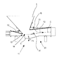
DETAILED DESCRIPTION OF THE INVENTION Referring to the accompanying drawings, an
設備1は、ドラム装置2から来る生成物Pを受け入れるための収集手段3、および一つの搬送経路Cに沿って伸び、そしてラベルのため収集手段3を一つの格納グループ5と接続する導管手段4を含む。その導管手段4に沿って、一つの第1段分離ユニットS1が、生成物Pから、該生成物Pの本体と最も重い材料を含む第1断片F1を分離するように構成され、且つボトルおよび/または容器並びにラベルを含む生成物の第2断片が搬送経路Cに沿って前進するように構成され、規定される。導管手段4に沿って、一つの第2段分離ユニットS2もまた、第2断片F2から、ボトルおよび/または容器を含む第3断片F3を分離するために構成され、且つ主にラベルを含む生成物の第4断片F4が、搬送経路Cに沿って前進するように構成され、規定される。
The
導管手段4の一つの終端8において、搬送経路Cの下流に設置された一つの終段ユニットが、格納グループ5の内部に、ラベルを含む第4断片F4を受け入れそして蓄積するためのS3として規定される。設備1は、第1段分離ユニットS1の上流に設置されたファン手段9を含み、該手段は、生成物の第2断片F2を第2段分離ユニットS2まで搬送するのに適した第1エアフローX1を生成するように構成されている。
At one end 8 of the conduit means 4, one end unit installed downstream of the transport path C is defined as S3 for receiving and accumulating the fourth fragment F4 containing the label inside the
設備1は、第3段分離ユニットS3の近傍に設置され、そしてラベルを含む第4断片F4を除去し、且つ格納グループ5に搬送するのに適した第2エアフローX2を生成するように構成された吸引手段10を含む。
The
第1段分離ユニットS1は、導管手段4の上に設けられた一つの第1の排出口6を経由して、生成物Pから第1断片F1を重力によって分離するように構成されているのに対して、第2段分離ユニットS2は、導管手段4の上に設けられた一つの第2排出口7を経由して、第2断片F2からボトルおよび/または容器を含む第3断片F3を重力によって分離するように構成されている。第2段分離ユニットS2は、第1段分離ユニットS1と終段ユニットS3の間に置かれている。第2排出口7から退出するボトルおよび容器は、引き続く断片への破砕および洗浄工程のため、一つの適切なステーションに移動させることができる。
The first stage separation unit S1 is configured to separate the first fragment F1 from the product P by gravity via one
導管手段4は、第1段ユニットS1の近傍に位置する一つの可変断面を有する第1導管部分11であって、収集手段3近傍の第1エアフローX1を加速するように構成された一つの合流区画と、さらに下流に第1エアフローX1のための一つの拡大区画を有する一つのチャンバーを含む第1導管部分を含む。第1排出口6は、可変断面を有する第1導管部分11の下部に設けられている。
The conduit means 4 is a
可変断面を有する第1導管部分11は、ベンチュリ効果が得られるように形作られており、および第1エアフローX1を偏向させ且つ導くための可調壁手段12、13を含む。可調壁手段12、13の位置は、第1エアフローX1の流体力学パラメータ、例えば、速度および圧力など、を変えるために調整することが可能であり、それにより、搬送経路Cに沿って生成物の第2断片F2に、所望の推進および引きずり動作が施される。
The
収集手段は、特に一つのホッパー要素3を含んでおり、その下部には、ドラム装置2から来る生成物Pのための一つの排出開口14が設けられている。
The collecting means comprises in particular a
可調壁手段12、13は、一つの偏向壁12を含んでおり、それは前述の排出開口14の上流に位置していて、その片側に、ファン手段9から来る空気の流れのための流出ポート15を画定している。偏向壁12の位置は、先述の空気の流れのための排出開口15の通過断面を変化させるために調整可能である。
The adjustable wall means 12, 13 comprise a deflecting
可調壁手段はさらに、一つの案内壁13を含んでおり、それは排出開口14の下流に位置していて、そして、その片側に、第1エアフローX1のための受入およびチャネリング区画を画定している。案内壁13の位置は、吸気断面および/または第1エアフローX1のための受入およびチャネリング区画16の幾何学的構成を変えるために調整することができる。
The adjustable wall means further includes a
偏向壁12および/または案内壁13は、搬送経路Cに対するそれらの傾斜を変化させるために回転自在に調整することができる。
The
導管手段4は、第1エアフローX1に対する層流状態の流体力学的条件が得られるような幾何学的形状に形成されており、これにより第1エアフローX1の内部においてボトルおよび/または容器に対する浮揚効果を促進することができる。特に、第1段ユニットS1および第2段ユニットS2の間において、導管断面は、一つの矩形輪郭を有しており、それにより、搬送中に、ボトルの分布を維持し、そして後者を、導管下部の壁近傍に、持ち上げられまた離されるように、すなわち、接触すること無く、維持することが可能になる。ラベルやその他の軽い物体は、したがって、ボトルと導管の壁の間に補足されたままとなることが防がれ、第2分離段S2にボトルとともに引き込まれそして排出される。 The conduit means 4 is formed in a geometrical shape so that a laminar hydrodynamic condition for the first airflow X1 is obtained, whereby a buoyancy effect on the bottle and / or container inside the first airflow X1. Can be promoted. In particular, between the first stage unit S1 and the second stage unit S2, the conduit cross section has a rectangular profile, thereby maintaining the distribution of the bottles during transport and In the vicinity of the lower wall, it is possible to keep it lifted and separated, i.e. without contact. Labels and other light objects are thus prevented from remaining trapped between the bottle and the wall of the conduit and are drawn into the second separation stage S2 with the bottle and discharged.
導管手段4は、第1段分離ユニットS1の下流に、実質的に水平な一つの第1導管セグメント20を含み、これに一つの第2導管セグメント21が接続され、そのさらに下流に搬送経路Cに沿って漸進的に高さが増すように上方に向けて傾斜をもって延在する。導管手段4は、第2導管セグメント21の下流に、さらに上方に向けて延在する一つの第3導管セグメント22を含む。第2段分離ユニットS2は、第2導管セグメント21および第3導管セグメント22をまたぐように規定される。
The conduit means 4 includes one
第3導管セグメント22の上には、第2段分離ユニットS2の近傍に、一つの空気吸気口30の開口が備えられ、それは、第2段ユニットS2の下流の第2エアフローX2を生成するために、吸引手段10をして外部から導管手段4の内部に空気を吸い込むことを可能にする。
Above the
空気吸気口30の開口は、例えば、摺動自在な一つの可動ポート要素32が連結された一つの穿孔されたプレート31を含み、所望の形態で空気吸気口30の開口を閉じることにより、空気吸気口30を通って吸引される空気の量を制御することができる。
The opening of the
第2段ユニットS2では、一つの連結管部19が下流に向かって徐々に細くなる形状をもって備えられており、その下部に、第2排出開口7が、ボトルや容器を含む生成物の第3断片F3のために設けられている。 In the second stage unit S2, one connecting pipe portion 19 is provided with a shape that becomes gradually narrower toward the downstream, and a second discharge opening 7 is provided at a lower portion of the third stage S2 of the product including bottles and containers. Provided for fragment F3.
第3導管セグメント22は、前述の格納グループ5に向けたボトルおよび/または容器の可能な前進を妨げるのに適した一つのジグザグ部23を含む。
The
導管手段4は、その一部が最大の高さをもって水平に延在する一つの第4導管セグメント24、それに次いで吸引手段10のところまで下方に延在することによって下降する一つの第5導管セグメント25、吸引手段10を格納グループ5に連結するように、最後に備えられた一つの終端導管26を含む。
The conduit means 4 has one
ファン手段9および第1段ユニットS1と第2段ユニットS2の間に包含されている導管手段4の一部は、第1エアフローX1が、第2断片F2のボトルおよび容器に、それらボトルおよび容器が第2段ユニットS2に到達するのに十分であるが、しかし、それを超えてしまわない力学的エネルギーおよび推進力を与え、引き続いて第2排出口7を降下し、そして通り抜けて出て行くことができるように構成されている。
Part of the conduit means 4 contained between the fan means 9 and the first stage unit S1 and the second stage unit S2 is such that the first airflow X1 is transferred to the bottle and the container of the second fragment F2. Is sufficient to reach the second stage unit S2, but provides mechanical energy and propulsion that does not exceed it, then descends the
吸引手段10および第2段ユニットS2と終段ユニット3の間に包含されているさらなる導管手段4の一部は、第2フローX2が、さらに搬送経路に沿ってボトルおよび容器を引きつけおよび引きずらないよう、それらボトルおよび容器に作用できないように構成されている一方、ラベルを含む第4断片F4のみを格納グループ5に向けて引きつけおよび引きずるのに十分な作用を及ぼすように構成されている。
Part of the suction means 10 and the further conduit means 4 contained between the second stage unit S2 and the
本設備は、ファン手段9および吸引手段10に操作上接続された一つの制御ユニット40を含んでおり、当該制御ユニットは、特別のプロセス上の需要に基づいて、並びに/または処理される生成物Pの型および特徴に基づいて決定された第1エアフローX1および第2エアフローX2の流体力学的パラメータを得るために、そのファン手段9および吸引手段10の駆動速度を制御するように構成されている。
The installation comprises a
これまでに述べられ、また添付図に示されている事柄から、本設備に加え、プラスチック製、特にPET製の容器およびボトルからラベル、キャップおよびその他の汚染物質を分離するための一つの方法が提供されていると理解されるのであり、その方法は、以下の工程:
− 収集手段3の中に、剥離ドラム装置2から退出し、ラベル、キャップ、その他の汚染物質、プラスチック製の容器および/またはボトルを含む生成物Pを受け入れること、および
− 本体および最も重い材料を含む生成物Pの第1断片F1が重力によって生成物Pから除去される第1除去ステージを実施すること、
− ラベル並びにボトルおよび/または容器を含む残留する生成物の第2断片F2を、導管手段4の内部および搬送経路Cに沿って前進させ、また搬送するために、ファン手段9によって第1エアフローX1を生成すること;
− 第2断片F2から、ボトルおよび/または容器を含む第3断片F3を重力によって分離する第2除去ステージS2を実施すること、
− 主にラベルを含む、生成物の、残留する第4断片F4を、さらに搬送経路Cに沿って除去し、および搬送するため、吸引手段10によって第2エアフローX2を生成すること、
− ラベルを含む第4断片F4が、格納グループ5の中に受け入れられ、そして蓄積される一つの終了ステージS3を実施すること
を含む。
From what has been described so far and shown in the accompanying drawings, in addition to this equipment, one method for separating labels, caps and other contaminants from plastic and especially PET containers and bottles is It is understood that the method comprises the following steps:
In the collecting means 3 withdrawing from the peeling
The first airflow X1 by the fan means 9 for advancing and transporting the second piece F2 of product, including the label and bottles and / or containers, along the conduit means 4 and along the transport path C; Generating;
-Performing a second removal stage S2 that separates from the second piece F2 by gravity the third piece F3 comprising bottles and / or containers;
Generating a second airflow X2 by the suction means 10 for further removing and transporting the remaining fourth fragment F4 of the product, mainly including the label, along the transport path C;
The fourth fragment F4 containing the label is received in
上に開示した方法および設備は、回収されたプラスチックにおいて極めて高い純度レベルが得られることを可能にし、且つ、本発明の設備1および方法による向上した分離効率のおかげで再利用プロセスの引き続く工程における水、添加剤および電気エネルギーの使用を削減することを可能にするのであり、したがって、財政水準における優位性をも達成することを可能にする。
The method and equipment disclosed above allow very high purity levels to be obtained in the recovered plastic and in the subsequent steps of the recycling process thanks to the improved separation efficiency with the
本発明の目的は、したがって、一般処理費用を削減し、且つ同時にリサイクルプロセスでの様々の材料の分離における極めて卓越した効率を、より安価に、そしてより簡単に達成するという一つの解決策を提供することによって達成された。 The object of the present invention therefore provides a solution that reduces the general processing costs and at the same time achieves a very excellent efficiency in the separation of various materials in the recycling process, cheaper and easier. Achieved by doing.
これまでに述べられ、また添付図に関連して示された事柄は、本発明による分離の方法と設備の一般的特徴を単に解説するために与えられたものであることが理解される:したがって、特許請求の範囲を逸脱することなく、本方法、全体のシステムまたはその一部に、他の修正や改変を加えることが可能である。特に、本設備の一つまたはそれ以上の部分を構成する幾何学的形態、寸法、位置および材料を、特別の運用上の要請に適合させるために選択し、および/または最適化することができる。 It will be understood that what has been described so far and which has been presented in connection with the accompanying drawings has been given merely to illustrate the general features of the separation method and equipment according to the present invention: Other modifications and alterations may be made to the method, the entire system, or parts thereof, without departing from the scope of the claims. In particular, the geometry, dimensions, position and materials that make up one or more parts of the installation can be selected and / or optimized to suit special operational requirements. .
Claims (22)
− 前記ドラム装置(2)から来る生成物(P)を受け入れるための収集手段(3)、一つの搬送経路(C)に沿って延在し、且つ前記収集手段(3)を、前記ラベルのための一つの格納グループ(5)に連結する導管手段(4)を含み、前記導管手段(4)に沿って:
− 一つの第1段分離ユニットであって、前記生成物(P)から、前記生成物(P)の本体および最も重い材料を含む第1断片(F1)を分離するように構成され、且つボトルおよび/または容器並びにラベルを含む前記生成物の第2断片(F2)が前記搬送経路(C)に沿って前進することを許容するように構成された第1段分離ユニット(S1);
− 一つの第2段分離ユニットであって、前記第2断片(F2)から、前記ボトルおよび/または容器を含む前記生成物の第3断片(F3)を分離するように構成され、且つ主に前記ラベルを含む前記生成物の第4断片(F4)が前記搬送経路(C)に沿って前進することを許容するように構成された第2段分離ユニット(S2)、を含み、そして、ここで、
− 前記導管手段(4)の一つの終端(8)において、前記搬送経路(C)の下流に位置する、一つの終段ユニットであって、前記格納グループ(5)の中に、前記ラベルを含む前記第4断片(F4)を受け入れ、そして蓄積するように構成された終段ユニット(S3);
− ファン手段であって、前記第1段分離ユニット(S1)の上流に位置し、且つ生成物の前記第2断片(F2)を前記第2段分離ユニット(S2)まで搬送するのに適した第1エアフロー(X1)を生成するように構成されたファン手段(9)、および
− 吸引手段であって、前記第3段分離ユニット(S3)の近傍に位置し、且つラベルを含む前記第4断片(F4)を捕らえ、および前記格納グループ(5)まで搬送するのに適した第2エアフロー(X2)を生成するように構成された吸引手段(10)
を規定することを特徴とする設備。 From plastic containers and bottles, labels, a facility for separating the cap and other contaminants (1), said equipment, rotary drum apparatus for removing the labels from each of the bottle (2) Suitable for installation downstream,
A collecting means (3) for receiving the product (P) coming from the drum device (2), extending along one conveying path (C), and the collecting means (3) being attached to the label Along the conduit means (4) comprising conduit means (4) connected to one containment group (5) for:
A first stage separation unit, configured to separate from the product (P) the body of the product (P) and the first piece (F1) containing the heaviest material, and a bottle And / or a first stage separation unit (S1) configured to allow a second piece (F2) of the product including a container and a label to advance along the transport path (C);
-A second stage separation unit, configured to separate from the second fragment (F2) the third fragment (F3) of the product comprising the bottle and / or container, and mainly A second stage separation unit (S2) configured to allow the fourth fragment (F4) of the product containing the label to advance along the transport path (C), and wherein so,
-At one end (8) of the conduit means (4), one final unit located downstream of the transport path (C), wherein the label is placed in the storage group (5); A final unit (S3) configured to accept and accumulate said fourth fragment (F4) comprising;
-Fan means, located upstream of the first stage separation unit (S1) and suitable for conveying the second piece of product (F2) to the second stage separation unit (S2) Fan means (9) configured to generate a first airflow (X1), and a suction means, said suction means being located in the vicinity of said third stage separation unit (S3) and including a label Suction means (10) configured to capture a fragment (F4) and generate a second airflow (X2) suitable for transporting to the storage group (5)
Equipment characterized by prescribing.
− 一つの剥離ドラム装置(2)を退出し、前記ラベル、キャップ、その他の汚染物質並びに前記プラスチック製の容器および/またはボトルからなる生成物(P)を収集手段(3)に受け入れること、および
− 前記生成物(P)から、該生成物(P)の本体および最も重い材料を含む第1断片(F1)を重力によって除去する第1除去ステージを実施すること、
− 導管手段(4)の内部において、および一つの搬送経路(C)に沿って、ラベル並びにボトルおよび/または容器を含む前記生成物の、残留する第2断片(F2)を前進させ且つ搬送するために、ファン手段(9)によって第1エアフロー(X1)を生成すること;
− 前記第2断片(F2)から、前記ボトルおよび/または容器を含む前記生成物の第3断片(F3)を分離する第2除去ステージ(S2)を実施すること;
− ラベルをその中に広く行き渡って含む前記生成物の、残留する第4断片(F4)を、吸引手段(10)によって除去し、およびさらに前記搬送経路(C)に沿って搬送するために第2エアフロー(X2)を生成すること、
− ラベルを含む前記第4断片(F4)を受け入れ、且つ一つの格納グループ(5)の中に蓄積する一つの終段(S3)を実施すること
を含む方法。 From plastic containers and bottles, a method for separating labels, caps and other contaminants, the following steps:
-Exiting one peeling drum device (2), receiving the product (P) consisting of the label, cap, other contaminants and the plastic container and / or bottle into the collecting means (3); and -Performing a first removal stage by gravity removing from the product (P) the body of the product (P) and the first piece (F1) containing the heaviest material;
Advancing and transporting the remaining second piece (F2) of said product, including labels and bottles and / or containers, inside the conduit means (4) and along one transport path (C) For generating a first airflow (X1) by means of fan means (9);
-Performing a second removal stage (S2) separating the third fragment (F3) of the product comprising the bottle and / or container from the second fragment (F2);
-The remaining fourth fragment (F4) of the product, including the label widely spread therein, is removed by suction means (10) and further transported along the transport path (C); Generating two airflows (X2);
-Accepting said fourth fragment (F4) containing a label and performing one final stage (S3) of accumulating in one storage group (5).
Applications Claiming Priority (3)
| Application Number | Priority Date | Filing Date | Title |
|---|---|---|---|
| ITMI2013A000849 | 2013-05-24 | ||
| IT000849A ITMI20130849A1 (en) | 2013-05-24 | 2013-05-24 | PLANT AND METHOD FOR SEPARATION OF LABELS AND OTHER MATERIALS FROM PLASTIC BOTTLES |
| PCT/EP2014/060736 WO2014187992A1 (en) | 2013-05-24 | 2014-05-23 | Plant and method for separating labels and other materials from plastic bottles |
Publications (3)
| Publication Number | Publication Date |
|---|---|
| JP2016520013A JP2016520013A (en) | 2016-07-11 |
| JP2016520013A5 JP2016520013A5 (en) | 2017-07-06 |
| JP6359090B2 true JP6359090B2 (en) | 2018-07-18 |
Family
ID=48877368
Family Applications (1)
| Application Number | Title | Priority Date | Filing Date |
|---|---|---|---|
| JP2016514443A Expired - Fee Related JP6359090B2 (en) | 2013-05-24 | 2014-05-23 | Equipment and method for separating labels and other substances from plastic bottles |
Country Status (10)
| Country | Link |
|---|---|
| US (1) | US9827693B2 (en) |
| EP (1) | EP3003670B1 (en) |
| JP (1) | JP6359090B2 (en) |
| CN (1) | CN105358299B (en) |
| ES (1) | ES2648985T3 (en) |
| HK (1) | HK1220950A1 (en) |
| IT (1) | ITMI20130849A1 (en) |
| PL (1) | PL3003670T3 (en) |
| PT (1) | PT3003670T (en) |
| WO (1) | WO2014187992A1 (en) |
Families Citing this family (11)
| Publication number | Priority date | Publication date | Assignee | Title |
|---|---|---|---|---|
| US11173627B2 (en) | 2016-02-02 | 2021-11-16 | Seiko Epson Corporation | Transport device and sheet manufacturing apparatus |
| CN106945196B (en) * | 2017-04-02 | 2019-02-12 | 佛山力合创新中心有限公司 | A kind of plastic beverage bottle Intelligent Compression machine people |
| CN106965346A (en) * | 2017-05-05 | 2017-07-21 | 晋江市恒里机械配件有限公司 | A kind of automatic screening bottle baling press and method |
| CN107377376B (en) * | 2017-09-02 | 2020-09-11 | 临武县华湘再生资源回收有限公司 | Automatic goods inspection machine for waste plastic bottles |
| US20190291139A1 (en) * | 2018-03-26 | 2019-09-26 | Michael C Centers | Secondary Separation System for Processing and Tracking Recyclables and Non- Recyclables |
| CN109795053B (en) * | 2019-02-01 | 2021-02-05 | 内蒙古益世源科技环保有限公司 | Waste plastic sorting machine |
| CN110860467A (en) * | 2019-11-22 | 2020-03-06 | 苏州嘉诺环境工程有限公司 | Material sorting system |
| CN110860468B (en) * | 2019-11-22 | 2021-09-21 | 苏州嘉诺环境工程有限公司 | Rotary air separation system |
| CN113001825A (en) * | 2021-02-19 | 2021-06-22 | 界首市金吴再生资源利用有限公司 | Label removing device for manufacturing special material for recycled polyester |
| CN113183357A (en) * | 2021-03-03 | 2021-07-30 | 广西梧州国龙再生资源发展有限公司 | PET plastic bottle recovery treatment process |
| CN114227989A (en) * | 2021-11-16 | 2022-03-25 | 湖北工程学院 | Multistage plastic winnowing mechanism |
Family Cites Families (41)
| Publication number | Priority date | Publication date | Assignee | Title |
|---|---|---|---|---|
| US2236548A (en) * | 1937-11-06 | 1941-04-01 | William B Prouty | Material disintegrating and air classifying system |
| US3729096A (en) * | 1972-06-02 | 1973-04-24 | M Fitzner | Apparatus for processing herbs and the like |
| US3843060A (en) * | 1973-06-20 | 1974-10-22 | Gen Tire & Rubber Co | Reclamation of fabric supported thermo-plastic sheet scrap |
| SE7415328L (en) * | 1974-12-06 | 1976-05-17 | Svenska Flaektfabriken Ab | PROCEDURE FOR SEPARATING THERMOPLASTIC MATERIAL IN THE FORM OF FILM FROM A HEAVY MIXTURE OF PAPER AND PLASTIC, AS WELL AS DEVICE FOR PERFORMING THE PROCEDURE |
| US3957631A (en) * | 1975-03-19 | 1976-05-18 | Lawrence Peska Associates, Inc. | Portable screening apparatus |
| NL8000791A (en) * | 1980-02-08 | 1981-09-01 | Esmil Bv | METHOD AND APPARATUS FOR SEPARATING PAPER AND PLASTIC FOIL IN A SIFTER. |
| US4915826A (en) * | 1984-03-27 | 1990-04-10 | Larry Nordhus | Grain cleaner |
| CN1041293A (en) * | 1988-04-22 | 1990-04-18 | 皇冠铁工公司 | Treatment device for particulate materials |
| US5110055A (en) * | 1989-04-03 | 1992-05-05 | Partek Corporation | Method and apparatus for cleaning thermoplastic material for reuse |
| US5115987A (en) * | 1991-02-19 | 1992-05-26 | Mithal Ashish K | Method for separation of beverage bottle components |
| US5236133A (en) * | 1991-12-04 | 1993-08-17 | Lundquist Lynn C | Method of container label removal |
| IT1255196B (en) * | 1992-06-30 | 1995-10-20 | Sorema Srl | HIGH TEMPERATURE SEPARATION PLANT FOR VARIOUS NATURE CONTAMINANTS FROM SMALL PIECE PLASTIC MATERIAL OR IN LEAVES |
| US5411142A (en) * | 1993-03-29 | 1995-05-02 | Abbott; Kenneth E. | Air-flow control for particle cleaning systems |
| US6019227A (en) * | 1994-11-16 | 2000-02-01 | May, Iii; Alexander Douglas | Extractor and separator apparatus |
| US5732827A (en) * | 1995-03-03 | 1998-03-31 | Portec Inc. | Screening apparatus |
| KR100271435B1 (en) * | 1998-09-10 | 2000-11-15 | 오해일 | Turn table type pet bottle reclaimed chip production automatic machine |
| DE10002682A1 (en) * | 2000-01-24 | 2001-08-02 | Krones Ag | Process for reprocessing PET components and device for carrying out the process |
| US20020125600A1 (en) * | 2000-10-31 | 2002-09-12 | David Horne | Plastic recycling system and process |
| US20020144935A1 (en) * | 2001-04-09 | 2002-10-10 | Donna Tims | Wheelbarrow sifter attachment |
| US6389646B1 (en) * | 2001-07-09 | 2002-05-21 | Victoria I. Pettigrew | Fiber tumbler and method of use |
| JP2003326521A (en) * | 2002-05-10 | 2003-11-19 | Ishikawajima Harima Heavy Ind Co Ltd | Method and apparatus for treating container |
| JP2004113900A (en) * | 2002-09-25 | 2004-04-15 | Rasa Ind Ltd | Equipment for separating polyvinyl chloride in waste plastic |
| JP4343519B2 (en) * | 2002-11-26 | 2009-10-14 | キヤノン株式会社 | Process cartridge plastic material recycling method |
| US6892516B1 (en) * | 2004-01-07 | 2005-05-17 | Salvatore Ardagna | Garden screening device for sifting and sorting material |
| US20060081513A1 (en) * | 2004-08-10 | 2006-04-20 | Kenny Garry R | Sorting recycle materials with automatically adjustable separator using upstream feedback |
| JP4546330B2 (en) * | 2005-05-31 | 2010-09-15 | アサヒビール株式会社 | Film removal device |
| ITMI20071759A1 (en) * | 2007-09-13 | 2009-03-14 | Previero Sas | METHOD AND PLANT FOR THE REMOVAL AND SEPARATION OF LABELS, CAPS AND CONTAMINANTS OF BOTTLES AND CONTAINERS OF PLASTIC MATERIAL |
| JP5239894B2 (en) * | 2009-01-23 | 2013-07-17 | 宇部興産株式会社 | Foreign material removal elbow pipe in airflow conveyance pipe |
| CA2760313A1 (en) * | 2009-04-28 | 2010-11-04 | Mtd America Ltd (Llc) | Apparatus and method for separating materials using air |
| JP5004060B2 (en) * | 2009-04-30 | 2012-08-22 | 三和産業株式会社 | PET bottle label separator |
| JP4488537B1 (en) * | 2009-05-22 | 2010-06-23 | 日本シーム株式会社 | Label separator for plastic containers |
| CN101596754B (en) * | 2009-06-04 | 2011-09-28 | 陆继泉 | Label peeling machine |
| PL2459326T5 (en) * | 2009-07-27 | 2022-02-07 | Herbold Meckesheim Gmbh | Method and apparatus for precleaning plastic parts |
| US8016117B2 (en) * | 2009-07-31 | 2011-09-13 | Mac Process Inc. | System and method for eliminating emissions from an air classification device |
| CN102049406B (en) * | 2009-10-29 | 2014-01-29 | 晶铁科技工业股份有限公司 | Label removing machine capable of reducing label removing reject ratio |
| US20110100882A1 (en) * | 2009-10-30 | 2011-05-05 | Beam Roger D | Portable solids screening bucket |
| IT1399363B1 (en) * | 2010-04-07 | 2013-04-16 | Previero Sas | METHOD AND EQUIPMENT FOR REMOVAL OF LABELS FROM CONTAINERS |
| CN202071242U (en) * | 2011-03-21 | 2011-12-14 | 胡群才 | Plastic bottle recovery device |
| US8523093B1 (en) * | 2011-04-14 | 2013-09-03 | Liviu Siladi | System for separating a plastic waste from a paper waste |
| JP6143339B2 (en) * | 2013-05-24 | 2017-06-07 | 本田技研工業株式会社 | Rotating drum type garbage separator |
| US9358583B1 (en) * | 2014-12-30 | 2016-06-07 | Richard B. Kahn | Portable powered sifter |
-
2013
- 2013-05-24 IT IT000849A patent/ITMI20130849A1/en unknown
-
2014
- 2014-05-23 US US14/893,453 patent/US9827693B2/en active Active
- 2014-05-23 WO PCT/EP2014/060736 patent/WO2014187992A1/en active Application Filing
- 2014-05-23 PL PL14726160T patent/PL3003670T3/en unknown
- 2014-05-23 JP JP2016514443A patent/JP6359090B2/en not_active Expired - Fee Related
- 2014-05-23 ES ES14726160.6T patent/ES2648985T3/en active Active
- 2014-05-23 PT PT147261606T patent/PT3003670T/en unknown
- 2014-05-23 CN CN201480029839.6A patent/CN105358299B/en not_active Expired - Fee Related
- 2014-05-23 EP EP14726160.6A patent/EP3003670B1/en active Active
-
2016
- 2016-07-29 HK HK16109075.1A patent/HK1220950A1/en not_active IP Right Cessation
Also Published As
| Publication number | Publication date |
|---|---|
| US9827693B2 (en) | 2017-11-28 |
| ITMI20130849A1 (en) | 2014-11-25 |
| JP2016520013A (en) | 2016-07-11 |
| US20160158966A1 (en) | 2016-06-09 |
| EP3003670B1 (en) | 2017-08-02 |
| EP3003670A1 (en) | 2016-04-13 |
| PT3003670T (en) | 2017-11-10 |
| PL3003670T3 (en) | 2018-04-30 |
| CN105358299B (en) | 2017-09-01 |
| CN105358299A (en) | 2016-02-24 |
| ES2648985T3 (en) | 2018-01-09 |
| HK1220950A1 (en) | 2017-05-19 |
| WO2014187992A1 (en) | 2014-11-27 |
Similar Documents
| Publication | Publication Date | Title |
|---|---|---|
| JP6359090B2 (en) | Equipment and method for separating labels and other substances from plastic bottles | |
| JP2016520013A5 (en) | ||
| JP5944907B2 (en) | Apparatus and method for treating bagging waste | |
| US11179729B2 (en) | Method and apparatus for washing and separating plastics material | |
| US8910797B2 (en) | Method and apparatus for separating plastics from compost and other recyclable materials | |
| US20120024760A1 (en) | Apparatus for drying pellets | |
| US20190321831A1 (en) | Method and apparatus for washing plastics materials | |
| CN112770851A (en) | Vacuum extraction for material sorting applications | |
| JP2003291144A (en) | Treatment apparatus for regenerating waste pet bottle and treatment method using the same | |
| US20080223770A1 (en) | Apparatus and method for separating plastic film from waste | |
| JP2005111736A (en) | Plastic waste fractionating and washing apparatus | |
| KR100883538B1 (en) | Glassware clushing system | |
| JP7189630B2 (en) | Waste treatment equipment for sorting recyclable fragments | |
| US20200222908A1 (en) | Device and method for separating material composites | |
| CN103658108B (en) | Infusion preparation with in bolt full-automatic gas blow cleaning machine | |
| KR100351749B1 (en) | pet-pellet air concentrator system | |
| JP4692907B2 (en) | Wind sorter | |
| US20130313343A1 (en) | Plastic material separation system and method | |
| CN203635549U (en) | Full-automatic air-blowing cleaning machine for inner caps for infusion preparations | |
| KR101539652B1 (en) | oil manufacturing system for waste | |
| CN214262325U (en) | Dry sorting device for stainless steel mixed material | |
| US20230264846A1 (en) | Thermoforming packaging machine with transverse cutting station | |
| KR20060089399A (en) | Window frame piece attached poly propylene film detaching device and method | |
| FR2945969A1 (en) | Textile fiber waste type fillers separation device, has inlet, outlet and strips arranged in separation column to define air flow channelized from inlet, so that flow raises in column, runs in position and in outlet strip towards outlet | |
| JP2005125129A (en) | Pneumatic sorting apparatus |
Legal Events
| Date | Code | Title | Description |
|---|---|---|---|
| A521 | Request for written amendment filed |
Free format text: JAPANESE INTERMEDIATE CODE: A523 Effective date: 20170522 |
|
| A621 | Written request for application examination |
Free format text: JAPANESE INTERMEDIATE CODE: A621 Effective date: 20170522 |
|
| A977 | Report on retrieval |
Free format text: JAPANESE INTERMEDIATE CODE: A971007 Effective date: 20180122 |
|
| A131 | Notification of reasons for refusal |
Free format text: JAPANESE INTERMEDIATE CODE: A131 Effective date: 20180214 |
|
| A521 | Request for written amendment filed |
Free format text: JAPANESE INTERMEDIATE CODE: A523 Effective date: 20180426 |
|
| TRDD | Decision of grant or rejection written | ||
| A01 | Written decision to grant a patent or to grant a registration (utility model) |
Free format text: JAPANESE INTERMEDIATE CODE: A01 Effective date: 20180523 |
|
| A61 | First payment of annual fees (during grant procedure) |
Free format text: JAPANESE INTERMEDIATE CODE: A61 Effective date: 20180619 |
|
| R150 | Certificate of patent or registration of utility model |
Ref document number: 6359090 Country of ref document: JP Free format text: JAPANESE INTERMEDIATE CODE: R150 |
|
| R250 | Receipt of annual fees |
Free format text: JAPANESE INTERMEDIATE CODE: R250 |
|
| LAPS | Cancellation because of no payment of annual fees |