JP6357157B2 - Respiratory lid structure - Google Patents
Respiratory lid structure Download PDFInfo
- Publication number
- JP6357157B2 JP6357157B2 JP2015534422A JP2015534422A JP6357157B2 JP 6357157 B2 JP6357157 B2 JP 6357157B2 JP 2015534422 A JP2015534422 A JP 2015534422A JP 2015534422 A JP2015534422 A JP 2015534422A JP 6357157 B2 JP6357157 B2 JP 6357157B2
- Authority
- JP
- Japan
- Prior art keywords
- lid
- main body
- column
- support
- hinge assembly
- Prior art date
- Legal status (The legal status is an assumption and is not a legal conclusion. Google has not performed a legal analysis and makes no representation as to the accuracy of the status listed.)
- Active
Links
Images


Classifications
-
- B—PERFORMING OPERATIONS; TRANSPORTING
- B65—CONVEYING; PACKING; STORING; HANDLING THIN OR FILAMENTARY MATERIAL
- B65D—CONTAINERS FOR STORAGE OR TRANSPORT OF ARTICLES OR MATERIALS, e.g. BAGS, BARRELS, BOTTLES, BOXES, CANS, CARTONS, CRATES, DRUMS, JARS, TANKS, HOPPERS, FORWARDING CONTAINERS; ACCESSORIES, CLOSURES, OR FITTINGS THEREFOR; PACKAGING ELEMENTS; PACKAGES
- B65D43/00—Lids or covers for rigid or semi-rigid containers
- B65D43/14—Non-removable lids or covers
- B65D43/16—Non-removable lids or covers hinged for upward or downward movement
- B65D43/163—Non-removable lids or covers hinged for upward or downward movement the container and the lid being made separately
- B65D43/166—Non-removable lids or covers hinged for upward or downward movement the container and the lid being made separately and connected by separate interfitting hinge elements fixed to the container and the lid respectively
-
- A—HUMAN NECESSITIES
- A61—MEDICAL OR VETERINARY SCIENCE; HYGIENE
- A61M—DEVICES FOR INTRODUCING MEDIA INTO, OR ONTO, THE BODY; DEVICES FOR TRANSDUCING BODY MEDIA OR FOR TAKING MEDIA FROM THE BODY; DEVICES FOR PRODUCING OR ENDING SLEEP OR STUPOR
- A61M16/00—Devices for influencing the respiratory system of patients by gas treatment, e.g. mouth-to-mouth respiration; Tracheal tubes
-
- E—FIXED CONSTRUCTIONS
- E05—LOCKS; KEYS; WINDOW OR DOOR FITTINGS; SAFES
- E05D—HINGES OR SUSPENSION DEVICES FOR DOORS, WINDOWS OR WINGS
- E05D7/00—Hinges or pivots of special construction
- E05D7/10—Hinges or pivots of special construction to allow easy separation or connection of the parts at the hinge axis
- E05D7/1061—Hinges or pivots of special construction to allow easy separation or connection of the parts at the hinge axis in a radial direction
- E05D7/1066—Hinges or pivots of special construction to allow easy separation or connection of the parts at the hinge axis in a radial direction requiring a specific angular position
-
- A—HUMAN NECESSITIES
- A61—MEDICAL OR VETERINARY SCIENCE; HYGIENE
- A61M—DEVICES FOR INTRODUCING MEDIA INTO, OR ONTO, THE BODY; DEVICES FOR TRANSDUCING BODY MEDIA OR FOR TAKING MEDIA FROM THE BODY; DEVICES FOR PRODUCING OR ENDING SLEEP OR STUPOR
- A61M16/00—Devices for influencing the respiratory system of patients by gas treatment, e.g. mouth-to-mouth respiration; Tracheal tubes
- A61M16/0003—Accessories therefor, e.g. sensors, vibrators, negative pressure
-
- A—HUMAN NECESSITIES
- A61—MEDICAL OR VETERINARY SCIENCE; HYGIENE
- A61M—DEVICES FOR INTRODUCING MEDIA INTO, OR ONTO, THE BODY; DEVICES FOR TRANSDUCING BODY MEDIA OR FOR TAKING MEDIA FROM THE BODY; DEVICES FOR PRODUCING OR ENDING SLEEP OR STUPOR
- A61M16/00—Devices for influencing the respiratory system of patients by gas treatment, e.g. mouth-to-mouth respiration; Tracheal tubes
- A61M16/10—Preparation of respiratory gases or vapours
- A61M16/14—Preparation of respiratory gases or vapours by mixing different fluids, one of them being in a liquid phase
- A61M16/16—Devices to humidify the respiration air
-
- B—PERFORMING OPERATIONS; TRANSPORTING
- B65—CONVEYING; PACKING; STORING; HANDLING THIN OR FILAMENTARY MATERIAL
- B65D—CONTAINERS FOR STORAGE OR TRANSPORT OF ARTICLES OR MATERIALS, e.g. BAGS, BARRELS, BOTTLES, BOXES, CANS, CARTONS, CRATES, DRUMS, JARS, TANKS, HOPPERS, FORWARDING CONTAINERS; ACCESSORIES, CLOSURES, OR FITTINGS THEREFOR; PACKAGING ELEMENTS; PACKAGES
- B65D43/00—Lids or covers for rigid or semi-rigid containers
- B65D43/02—Removable lids or covers
- B65D43/0202—Removable lids or covers without integral tamper element
- B65D43/0225—Removable lids or covers without integral tamper element secured by rotation
-
- B—PERFORMING OPERATIONS; TRANSPORTING
- B65—CONVEYING; PACKING; STORING; HANDLING THIN OR FILAMENTARY MATERIAL
- B65D—CONTAINERS FOR STORAGE OR TRANSPORT OF ARTICLES OR MATERIALS, e.g. BAGS, BARRELS, BOTTLES, BOXES, CANS, CARTONS, CRATES, DRUMS, JARS, TANKS, HOPPERS, FORWARDING CONTAINERS; ACCESSORIES, CLOSURES, OR FITTINGS THEREFOR; PACKAGING ELEMENTS; PACKAGES
- B65D43/00—Lids or covers for rigid or semi-rigid containers
- B65D43/26—Mechanisms for opening or closing, e.g. pedal-operated
-
- E—FIXED CONSTRUCTIONS
- E05—LOCKS; KEYS; WINDOW OR DOOR FITTINGS; SAFES
- E05B—LOCKS; ACCESSORIES THEREFOR; HANDCUFFS
- E05B65/00—Locks or fastenings for special use
- E05B65/52—Other locks for chests, boxes, trunks, baskets, travelling bags, or the like
-
- E—FIXED CONSTRUCTIONS
- E05—LOCKS; KEYS; WINDOW OR DOOR FITTINGS; SAFES
- E05D—HINGES OR SUSPENSION DEVICES FOR DOORS, WINDOWS OR WINGS
- E05D3/00—Hinges with pins
- E05D3/02—Hinges with pins with one pin
- E05D3/022—Hinges with pins with one pin allowing an additional lateral movement, e.g. for sealing
-
- A—HUMAN NECESSITIES
- A61—MEDICAL OR VETERINARY SCIENCE; HYGIENE
- A61M—DEVICES FOR INTRODUCING MEDIA INTO, OR ONTO, THE BODY; DEVICES FOR TRANSDUCING BODY MEDIA OR FOR TAKING MEDIA FROM THE BODY; DEVICES FOR PRODUCING OR ENDING SLEEP OR STUPOR
- A61M16/00—Devices for influencing the respiratory system of patients by gas treatment, e.g. mouth-to-mouth respiration; Tracheal tubes
- A61M16/10—Preparation of respiratory gases or vapours
- A61M16/14—Preparation of respiratory gases or vapours by mixing different fluids, one of them being in a liquid phase
- A61M16/16—Devices to humidify the respiration air
- A61M16/162—Water-reservoir filling system, e.g. automatic
-
- A—HUMAN NECESSITIES
- A61—MEDICAL OR VETERINARY SCIENCE; HYGIENE
- A61M—DEVICES FOR INTRODUCING MEDIA INTO, OR ONTO, THE BODY; DEVICES FOR TRANSDUCING BODY MEDIA OR FOR TAKING MEDIA FROM THE BODY; DEVICES FOR PRODUCING OR ENDING SLEEP OR STUPOR
- A61M2209/00—Ancillary equipment
- A61M2209/06—Packaging for specific medical equipment
-
- E—FIXED CONSTRUCTIONS
- E05—LOCKS; KEYS; WINDOW OR DOOR FITTINGS; SAFES
- E05Y—INDEXING SCHEME RELATING TO HINGES OR OTHER SUSPENSION DEVICES FOR DOORS, WINDOWS OR WINGS AND DEVICES FOR MOVING WINGS INTO OPEN OR CLOSED POSITION, CHECKS FOR WINGS AND WING FITTINGS NOT OTHERWISE PROVIDED FOR, CONCERNED WITH THE FUNCTIONING OF THE WING
- E05Y2900/00—Application of doors, windows, wings or fittings thereof
- E05Y2900/60—Application of doors, windows, wings or fittings thereof for other use
- E05Y2900/602—Application of doors, windows, wings or fittings thereof for other use for containers
-
- Y—GENERAL TAGGING OF NEW TECHNOLOGICAL DEVELOPMENTS; GENERAL TAGGING OF CROSS-SECTIONAL TECHNOLOGIES SPANNING OVER SEVERAL SECTIONS OF THE IPC; TECHNICAL SUBJECTS COVERED BY FORMER USPC CROSS-REFERENCE ART COLLECTIONS [XRACs] AND DIGESTS
- Y10—TECHNICAL SUBJECTS COVERED BY FORMER USPC
- Y10T—TECHNICAL SUBJECTS COVERED BY FORMER US CLASSIFICATION
- Y10T29/00—Metal working
- Y10T29/49—Method of mechanical manufacture
- Y10T29/49826—Assembling or joining
- Y10T29/4984—Retaining clearance for motion between assembled parts
-
- Y—GENERAL TAGGING OF NEW TECHNOLOGICAL DEVELOPMENTS; GENERAL TAGGING OF CROSS-SECTIONAL TECHNOLOGIES SPANNING OVER SEVERAL SECTIONS OF THE IPC; TECHNICAL SUBJECTS COVERED BY FORMER USPC CROSS-REFERENCE ART COLLECTIONS [XRACs] AND DIGESTS
- Y10—TECHNICAL SUBJECTS COVERED BY FORMER USPC
- Y10T—TECHNICAL SUBJECTS COVERED BY FORMER US CLASSIFICATION
- Y10T292/00—Closure fasteners
- Y10T292/57—Operators with knobs or handles
Description
本発明は概して呼吸装置に関する。詳細には本発明は、呼吸ガスが容器中の液体の表面上を通過した後、陽圧で供給される呼吸装置に関する。 The present invention relates generally to respiratory devices. In particular, the invention relates to a breathing apparatus in which breathing gas is supplied at a positive pressure after passing over the surface of the liquid in the container.
閉鎖性睡眠中無呼吸のCPAP療法は、加圧された通気性ガス、一般的に空気を、導管およびマスクなどの使用者インターフェースを使用して、使用者の気道に送り届けることを必要とする。CPAPに採用されるガス圧は一般的に、使用者の条件に依存して、(使用者インターフェースで測定される)最大約180L/minの流速で、約4cmH2Oから約28cmH2Oまでの範囲内にある。加圧ガスは使用者の気道の空気圧副子としての役割を果たす。従って、加圧ガスは気道がつぶれる可能性を低減する。 CPAP therapy for obstructive sleep apnea requires pressurized breathable gas, typically air, to be delivered to the user's airway using a user interface such as a conduit and mask. Typically the gas pressure employed in CPAP, depending on the condition of the user, at a flow rate of up to about 180L / min (measured as in the user interface), from about 4 cmH 2 O to about 28cmH 2 O Is in range. The pressurized gas serves as a pneumatic splint for the user's airway. Thus, pressurized gas reduces the possibility of airway collapse.
CPAP機械は、加圧ガスを供給する気道形成装置を含み、多くのCPAP機械は、加圧ガスを加湿するための加熱水浴または他の水源を含む。CPAP機械は、寝室または他の寝るための区画で使用されることが多く、例えばナイトテーブル上に配置される。従って、CPAP機械の設置面積を低減することは望ましい。さらに、ナイトテーブルの上面の限定された空間を考慮すると、CPAP機械は、可能な限り壁の近くへ押されることが多い。 CPAP machines include airway forming devices that supply pressurized gas, and many CPAP machines include a heated water bath or other water source to humidify the pressurized gas. CPAP machines are often used in bedrooms or other sleeping compartments, for example on a night table. Therefore, it is desirable to reduce the footprint of the CPAP machine. Furthermore, considering the limited space on the top of the night table, CPAP machines are often pushed as close to the wall as possible.
CPAP機械が使用される窮屈な空間のため、水槽等を密閉するために使用される蓋または他の構成要素の簡単な操作が望まれる。好ましくは、蓋または他のそのような構成要素は、ヒンジの周りを簡単に回転可能である。さらに好ましくは、ヒンジは、隣接する外側表面と概ね面一であるか、その中にのめり込むように構成される。さらにより好ましくは、ヒンジは、機械内の空気圧によって発生する力(例えば、概ね水平の蓋に対する垂直の力)に対抗する拘束を提供し、その一方、蓋が開放する間限度を超えて広げられるとき蓋の取外しを許容する。 Due to the tight space in which CPAP machines are used, simple manipulation of lids or other components used to seal water tanks or the like is desired. Preferably, the lid or other such component is simply rotatable about the hinge. More preferably, the hinge is configured to be substantially flush with or recessed into the adjacent outer surface. Even more preferably, the hinge provides a constraint to counteract the forces generated by the air pressure in the machine (eg, a vertical force against a generally horizontal lid), while being expanded beyond the limit while the lid opens. Sometimes allow the lid to be removed.
さらに、水槽にアクセスする能力を改善するために、蓋は、使用者が片手で蓋をあけることができるように、好ましくはラッチ機構を支持する。換言すると、片手で、好ましくは1つの位置にある片手で、ラッチを操作可能であり、蓋を開けることができる。そのような構造は、ラッチを操作するために片手を必要とし、続けて蓋を上げるためにもう片方の手を必要とする構造に優る歓迎される改善である。 Further, to improve the ability to access the aquarium, the lid preferably supports a latch mechanism so that the user can open the lid with one hand. In other words, the latch can be operated with one hand, preferably with one hand in one position, and the lid can be opened. Such a structure is a welcome improvement over structures that require one hand to operate the latch and then require the other hand to raise the lid.
いくつかの構造では、呼吸補助装置は蓋および主要本体を含み、蓋および主要本体は選択的にキャビティを密閉する。蓋はボタン部材および少なくとも1つのヒンジアセンブリを含む。 In some constructions, the respiratory assistance device includes a lid and a main body that selectively seals the cavity. The lid includes a button member and at least one hinge assembly.
いくつかの構造では、蓋はさらに、ボタン部材が押圧される間1つまたは複数の指の先端と係合されるように作られた構成要素を含む。 In some constructions, the lid further includes a component that is configured to engage the tip of one or more fingers while the button member is pressed.
いくつかの構造では、ボタン部材は、少なくとも1つのヒンジアセンブリから外方へばね付勢される。 In some constructions, the button member is spring biased outward from the at least one hinge assembly.
いくつかの構造では、少なくとも1つのヒンジアセンブリは、主要本体に対する蓋の回転移動を可能にする。 In some constructions, the at least one hinge assembly allows for rotational movement of the lid relative to the main body.
いくつかの構造では、ヒンジアセンブリは、少なくとも1つの柱および少なくとも1つの支持部を含み、支持部は柱にのしかかり、柱は蓋の外周の内側に位置付けられる。 In some constructions, the hinge assembly includes at least one post and at least one support, the support rests on the post, and the post is positioned inside the outer periphery of the lid.
好ましくは、ヒンジアセンブリは、柱の少なくとも軸方向長さに沿って延在するクリップを含み、クリップは、柱がクリップと支持部との間に捕捉されるように、柱の、支持部と反対の側に位置付けられる。 Preferably, the hinge assembly includes a clip that extends along at least the axial length of the post, the clip being opposite the support of the post so that the post is captured between the clip and the support. Positioned on the side of
いくつかの構造では、少なくとも1つのヒンジアセンブリは、案内構造およびカム構造を含み、案内構造およびカム構造は、柱が回転する間、柱の滑り運動を引き起こすように構成される。 In some structures, the at least one hinge assembly includes a guide structure and a cam structure, the guide structure and cam structure being configured to cause a sliding motion of the column while the column rotates.
いくつかの構造では、案内構造は案内表面を含み、使用中、案内表面はカム構造と接触し、蓋の閉鎖移動の結果として柱の滑り運動を介して蓋を主要本体に対して取り外された状態から取り付けられた状態へ移動する。 In some constructions, the guide structure includes a guide surface, and in use, the guide surface contacts the cam structure and the lid is removed from the main body via a sliding motion of the column as a result of the closure movement of the lid. Move from state to attached state.
好ましくは、滑り運動は、蓋が主要本体に対して切り離された状態から係合された状態へ移動されるときだけ起きる。 Preferably, the sliding movement occurs only when the lid is moved from the disconnected state to the engaged state with respect to the main body.
好ましくは、柱の滑り運動は、支持部が柱の上に少なくとも垂直に位置付けられ、蓋が閉鎖された位置にある状態で、実質的に水平である。 Preferably, the sliding motion of the column is substantially horizontal with the support positioned at least vertically on the column and the lid in the closed position.
いくつかの構造では、少なくとも1つの支持部は開口部を画定し、開口部は、使用中、蓋を主要本体に対して取り外された状態から取り付けられた状態へ移動させることができるように、少なくとも1つの柱が開口部を通過することを許容する。 In some constructions, the at least one support defines an opening that allows the lid to move from a detached state to an attached state relative to the main body during use. Allow at least one pillar to pass through the opening.
いくつかの構造では、呼吸装置の蓋を開放する方法は、蓋をラッチ解除するためにボタン部材を係合構成要素の方へ移動させるステップと、続いて、使用者が手の位置を変える必要なく蓋を開放位置へ回転させるステップとを含む。 In some constructions, the method of opening the lid of the breathing apparatus involves moving the button member toward the engaging component to unlatch the lid, followed by the user repositioning the hand Without rotating the lid to the open position.
いくつかの構造では、蓋を呼吸装置の主要本体に係合する方法は、蓋が開放位置にある状態で柱を少なくとも1つの支持部材と平行に配置するステップと、蓋を閉鎖位置の方へ回転させるステップであって、その結果、蓋に形成された少なくとも1つの係合構造と、主要本体に形成された少なくとも1つの係合構造とにより蓋は係合された構造にされ、ここで蓋は係合された構造であるが回転可能な状態であるステップとを含む。 In some constructions, the method of engaging the lid to the main body of the breathing apparatus includes placing the column parallel to the at least one support member with the lid in the open position, and moving the lid toward the closed position. Rotating, so that the lid is engaged by at least one engagement structure formed on the lid and at least one engagement structure formed on the main body, wherein the lid Includes an engaged structure, but a rotatable state.
本発明のこれらおよび他の特徴、態様および利点を、以下の図面を参照して記載する。 These and other features, aspects and advantages of the present invention are described with reference to the following drawings.
図1は、本発明の特定の特徴、態様および利点に従い配置かつ構成された呼吸補助装置100を示す。装置100は、主要本体102および蓋104を含む。主要本体102および蓋104は一緒にハウジング106を画定し、ハウジング106は、容器、槽、タンクまたは他の液体本体(不図示)をキャビティ内に密閉する、または全体的に包み込む。
FIG. 1 illustrates a respiratory assistance device 100 arranged and configured in accordance with certain features, aspects and advantages of the present invention. Device 100 includes a
示されている本体102は、少なくとも1つの外側表面110を含む。示されている構造では、本体102は、4つの概ね平坦な外側表面110を含み、それらは丸い角112で接続される。他の構造が可能である。
The illustrated
蓋104はヒンジアセンブリ114で本体102に接続される。示される構造では、蓋104は2つのヒンジアセンブリを使用して主要本体102の後部に接続される。蓋104は他の表面に接続可能である。さらに、蓋104は、わずか1つのヒンジアセンブリ114、または2つより多いヒンジアセンブリ114を使用して主要本体102に接続可能である。好ましくはヒンジアセンブリ114は、蓋104が閉鎖した状態で(例えば図1に示されるように)、ヒンジアセンブリ114が概ね後部外側表面110と面一になるかその中にのめり込むように構成される。いくつかの構造では、ヒンジアセンブリ114は、ヒンジアセンブリが後部外側表面110の後方に突出しないように構成される。いくつかの構造では、ヒンジ特徴部のいくつかは、後部外側表面の1つまたは複数の周囲表面、または装置の他の周囲部分からほんのわずか突出してもよい。いくつかの構造では、蓋104は外周面116を含み、ヒンジアセンブリ114は、蓋104の外周面116の外方に実質的に突出しない。
The
図2を参照すると、ヒンジアセンブリ114は、少なくとも1つの柱120および少なくとも1つの支持部122を含む。好ましくは、少なくとも1つの柱120は、柱が蓋の外周面116の内側にのめり込みかつ位置付けられるように取り付けられる。示される構造は、2つの支持部122に接続される1つの柱120を含む。いくつかの構造では、少なくとも1つの柱120は蓋104に取り付けられ、その一方、少なくとも1つの支持部122が主要本体102に取り付けられる。いくつかの構造では、少なくとも1つの柱120は主要本体102に取付け可能であり、その一方、少なくとも1つの支持部122が蓋104に取付け可能である。
Referring to FIG. 2, the
少なくとも1つの柱120は、1つまたは複数のスタンドオフ(standoff)124を使用して蓋104に固定可能である。示される構造では、スタンドオフ124は2つの支持部122の間に位置付けられる。スタンドオフは支持部122の領域において柱120の撓みを低減する。いくつかの構造では、スタンドオフ124の間に延びる柱120の部分126は省略可能である。しかしながら、示される構造では、柱120の部分126はクリップ130によって固定可能である。クリップ130は、柱120を収容する凹部または他のいずれか適切な構造を有することができる。
At least one
示される構造においてクリップ130によって柱120に生成される力は、例えば、支持部122によって生成される力によって対向される。クリップ130は、支持部122と柱120の間の接触領域に関して柱120の反対側と接触可能である。いくつかの構造では、クリップ130は、柱120とクリップ130を組み立てる間、柱120から離れて曲がるように構成可能である。例えば、クリップ130は、主要本体102から後方に延びる可撓性フィンガであることができる。支持部122は、柱120の周囲面の少なくとも一部を受け入れる後方に開口する開口部を画定する凹部を有することができる。従って、矢印で示される方向における柱120の移動の結果、支持部122およびクリップ130に対する柱120の取付けおよび取外しがもたらされ得る。また、支持部122の後方に開口する開口部は、柱120にのしかかる構造をもたらし、その結果、柱120が支持部122の開口部内に完全に受け入れられているので支持部122に対する柱120の垂直移動は不可能である。従って、治療の間、蓋104が主要本体102から分離する可能性は低い。
The forces generated by the
図3を参照すると、蓋104および主要本体102は、柱120およびクリップ130および支持部122を接続するように案内する構成を含むことができる。いくつかの構造では、この構成により、蓋104が主要本体102上で閉鎖位置の方へ移動されるとき、少なくとも1つの柱120が支持部122の開口部へ移動し、およびクリップ130と係合することが容易になる。示される構造では、2つの案内構造140が2つの支持部122の外側に位置付けられている。他の構造も可能である。
Referring to FIG. 3, the
図4を参照すると、案内構造140は、カム構造144を受け入れる凹部142を含む。カム構造144は、蓋104が主要本体102上で完全に閉鎖された位置へ移動された状態で、カム構造144が蓋104が完全に閉鎖することを邪魔しないように、凹部142内に受け入れられる。カム構造144は、カム構造144の厚さが後部から前部まで増大するように傾斜表面146によって先端に向かってテーパする一方、案内構造は対向表面150を有する。傾斜表面146および対向表面150は互いに係合し、その結果、傾斜表面146および対向表面150は、蓋104が少なくとも部分的に閉鎖された位置にあるとき、主要本体102に対する蓋104の取外し方向(図2参照)の移動に抵抗する。
Referring to FIG. 4, the
さらに、蓋104が閉鎖位置(例えば図1)に回転されるとき、傾斜表面146および対向表面150は、蓋104を前方へ引き、取付位置へ位置付けるように作用する(例えば、少なくとも1つの柱120が支持部122およびクリップ130に接続される)。従って、蓋104の回転の結果、ヒンジアセンブリ114は取り外された状態から動作可能に接続されることができる。いくつかの構造では、初期接触から完全閉鎖までの傾斜表面146および対向表面150の厚さの差は、柱120の外側表面および支持部122との第1の接触部からの距離と実質的に同じであり、その結果、傾斜表面146および対向表面150がそれらの長さに沿って完全係合するように移動するとき、柱120は支持部122およびクリップ130内の位置へ引かれる。
Further, when the
特に、蓋104が主要本体102に対して開放位置(例えば図3)にある状態で、十分な空間が傾斜表面146と対向表面150との間に存在し、その結果、蓋104は力を適用することによって主要本体102から分離することができる。有利には、そのような構成により、柱120を支持部122およびクリップ130から切り離すことによって蓋104および主要本体102の間の分離が可能になる。そのような分離は、蓋をあけ過ぎることによって発生する力、または装置100の起こり得る誤用から発生する損傷から装置100を保護することができる。従って、蓋104を主要本体102から分離する能力は、装置100を永久的な損傷から保護することができる。上で考察したように、蓋104は柱120を支持部122と平行に配置し、かつ蓋104を閉鎖位置へ回転させることによって簡単に再接続可能であり、回転の結果、カム構造144の傾斜表面146および案内構造の対向表面150は構成要素を一緒に引き戻す。
In particular, with the
次に図5を参照して、蓋104の解放および把持アセンブリ160を記載する。示されるように、解放および把持アセンブリ160は、蓋104に取り付けられる少なくとも1つのボタン部材162を含む。いくつかの構造では、ボタン部材162は、ヒンジアセンブリ162の方へおよびそれから離れる方へ移動するように取り付けられる。いくつかの構造では、ボタン部材162は、ヒンジアセンブリ114を有する蓋104の側に隣接する蓋104の側に沿って取付け可能である。示される構造では、ボタン部材162は、ヒンジアセンブリ114に関して蓋104の反対側に取り付けられ、ヒンジアセンブリ114の方へおよびそれから離れる方へ移動可能である。
Referring now to FIG. 5, the
ボタン部材162は図6に示される。ボタン部材は外側表面164を含み、これは図5に最もよく示されている。外側表面164は、指または親指と接触するのに十分に大きい。図5にも示されているように、蓋104は、蓋104を持ち上げるために使用される構成要素166を含むことができる。示される構造では、構成要素166は窪んだ領域であり、これは外側表面164と概ね平行に延びる壁170を有する。好ましくは、窪んだ領域166は、指の少なくとも先端を収容するのに十分に大きい。いくつかの構造では、構成要素166は、1つまたは複数のリップ、隆起部、突起、凹部などである。従って、構成要素166(例えば壁170を有する)および外側表面164は、簡単な絞り作用がボタン部材162の掛け外れならびに掴み作用の提供を達成することを可能にし、主要本体102から離れる蓋104の移動を可能にする。
The
再度図6を参照すると、示されるボタン部材162は2つの外側柱172を含む。柱172は、例えばおよび限定せずにばね等などの付勢部材と係合するように寸法決めされ、かつ構成される。柱172は、蓋104に形成される対応するハウジング174内に受け入れられる。ハウジング174は付勢部材を含むことができ、柱172は、付勢部材の付勢力に対抗してハウジング174に出入りするように滑動することができる。
Referring again to FIG. 6, the illustrated
示されるボタン部材162はまた、少なくとも1つのタブ176を含む。示される構造では、ボタン部材162は2つのタブ176を含む。タブ176は端部にかかり180を有するバヨネット状である。図7に示されるように、タブ176は蓋104に形成される構造182と係合することができる。従ってタブ176は、その構造と協働して、ボタン部材162が蓋104の凹部から出る可能性を低減し、一方でボタン部材162が蓋104に対して内側に押されることを許容する。
The illustrated
構造182はまた、ボタン部材162に取り付けられるかそこに形成されたフィンガ186を受け入れる通路184を含む。通路184は、大まかに言えば蓋104に対するボタン部材162の直線並進移動をもっぱら容易にする。換言すると、通路184はフィンガ186を受け入れ、フィンガ186は通路184によって実質的に直線状の移動に概ね制限される。
The
フィンガ186はロック用柱190を支持する。ロック用柱190は、主要本体102に形成された構造と係合することができる。いくつかの構造では、ロック用柱190は、主要本体102の内側表面に形成された構造と係合し、その結果、ボタン部材162を押圧することによりロック用柱190と、ロック用柱190が通常係合する前記構造との間に分離がもたらされる。ボタン部材162の解放により、付勢部材はロック用柱190をロック用柱190が通常係合する前記構造と再係合する位置に移動する。
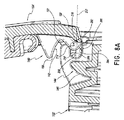
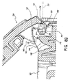
図8A〜8Dは、主要本体102に対するいくつかの位置で蓋104を示す。図8Aは第1開放位置にある蓋104を示す。図8Bおよび8Cは、図8Aの第1開放位置に対して徐々にさらに閉鎖される位置にある蓋104を示す。図8Dは閉鎖位置にある蓋104を示す。特に、図8A〜8Dはさらに、蓋104が開放位置から閉鎖位置へ移動するときの、カム構造144の傾斜表面、またはカム表面146と、蓋凹部142の対向表面(案内表面またはカムフォロワ表面とも呼ばれる)150との相互作用を示す。本明細書に記載されるように、カム構造144および凹部142は、蓋104が開放位置から閉鎖位置へ移動されるとき、蓋104を、主要本体102に対して取り外された位置から、主要本体102に対して取り付けられた位置へ移動するように相互作用することができる。
8A-8D show the
本明細書に記載されるように、支持部122は開口部202を含む凹部200を含み、開口部202は示される構成では後方に開口する。好ましくは、凹部200は細長い形状であり、全体的に前後方向に延在する。示される構成では、凹部200は全体的にまたは実質的に水平であるか、主要本体102の底部支持表面と整列され、その結果、凹部200は、装置100が平坦表面に置かれるとき、全体的にまたは実質的に水平である。凹部200は上側および下側案内表面204を含み、それらは開口部202から端部表面206まで前方に延在する。本明細書に記載されるように、支持部122はまた、蓋104を主要本体102から分離する傾向のあるハウジング106内の力(例えば内側圧力によりもたらされる力)に応答して蓋104を主要本体102に保持することを補助する。従って、端部表面206の上側部分および/または上側案内表面204は、柱120と接触する保持表面を形成可能であり、蓋104を主要本体102から分離する傾向のある力に応答して、蓋104、または支持部122および/またはヒンジ114に近い蓋104の少なくとも一部(例えば後方部分)を、主要本体102に保持する。
As described herein, the
示される構成では、端部表面206は、側面からの形状において湾曲され(例えば半円形)、上側案内表面204および下側案内表面204と接続する。示される支持部122は、横方向すなわち側面から側面へ向かう方向において細長く、従って、3次元の実質的に半円筒形状を画定する。しかしながら便宜上、ヒンジ114、案内構造140およびカム構造144は、本明細書中、図8A〜8Dの側面図の文脈において、2次元の用語で記載することができる。記載される構造はまた、装置100に対して幅寸法を、すなわち図8A〜8Dの側面図に対して深さ寸法を有することも認識される。
In the configuration shown,
示される端部表面206は、中心点210(すなわち3次元における軸)からの半径208を有する曲線によって画定される。凹部200は長手軸212を有することができ、長手軸212は、概ね開口部202から端部表面206まで凹部200の長さに沿って延在し、示される構造では、中心点210を通って延びる。軸212は、上側および下側案内表面204の1つまたは両方と整列されることができるかそれらと平行であることができ、または(例えばおよび限定せずに、テーパした凹部の場合など)案内表面204間の中心に位置付け可能である。示される構造では、軸212は、全体的にまたは実質的に水平(すなわち主要本体102の底面と平行)である。しかしながら他の構造では、軸212は非水平、すなわち主要本体102の底面に対して傾けられてもよい。
The
本明細書に記載されるように、柱120は好ましくは円筒状の形状である、すなわち図8A〜8Dに示されるように側面から見て円形の形状である。柱120は中心点214(すなわち3次元の軸)および半径216を決定する。好ましくは、柱120の半径216は、端部表面206の半径208と実質的に等しく、その結果、柱120は、端部表面206に対してぴったりと位置付け可能であり、また中心点210、214が実質的に互いに整列した状態で、すなわち同軸である状態で、凹部200内で垂直方向に制限可能である。
As described herein, the
好ましくは、カム構造144のカム表面または傾斜表面146は、蓋104が開放位置から閉鎖位置の方へ移動されるとき、柱120が凹部200の軸212に沿って端部表面206の方へ移動されるように、端部表面206および/または中心点210に対して位置付けられる、または方向付けられる。示される構成では、第1の距離220が、傾斜表面146の第1地点または位置222と、中心点210との間に定められ、第2の距離224が、傾斜表面146の第2地点または位置226と、中心点210との間に定められる。好ましくは、第1地点222は傾斜表面146の初期部分に位置付けられ、第2地点226は傾斜表面146の後続部分に位置付けられ、その結果、対向表面150は、蓋104が開放位置から閉鎖位置へ移動されるとき、第2地点226の前に第1地点222と接触する。第1地点222は、蓋104が閉鎖する間、対向表面150によって最初に接触される位置であるかその近くであることができ、第2地点226は、蓋104が閉鎖位置にあるとき、対向表面150によって接触される傾斜表面146に沿ったさらに遠い位置であるかその近くであることができる。第1の距離220は好ましくは第2の距離224より短く、その結果、蓋104が開放位置から閉鎖位置へ移動されるとき、および対向表面150が傾斜表面146に沿って第1地点222から第2地点226に向かう方向に移動するとき、凹部200の軸212に沿った柱120の移動が引き起こされる。
Preferably, the cam surface or
蓋104が好ましくは閉鎖されたとき凹部200内で柱120の中心点214によって移動された距離228は、第2距離224と第1距離220の間の距離230に実質的に等しい。距離228は凹部200の全長未満であることができる。案内構造140によって端部表面206に引かれる前、柱120を凹部200内に少なくとも部分的に位置付けすることができるためである。他の構成では、距離228は凹部200の長さと実質的に等しくてもよい。すぐ上に記載した距離は中心点210および214に関連しているが、距離は同様に、所望なら、非円形(すなわち非円筒)の凹部または柱の形状の文脈においてなど、それぞれ凹部200(例えば端部表面206)および柱120上の位置の他の地点に対して測定されてもよい。
The distance 228 moved by the center point 214 of the
図8Aは、主要本体102に対して第1開放位置にある蓋104を示し、第1開放位置は、蓋104の再取付プロセスを開始するときなど、完全に開放した位置であり得る。示されるように、対向表面150は、蓋104の後方移動(例えば取外し)か許容されるように、傾斜表面146から離されている。有利には、そのような構成により、蓋104に適用される過剰な開放力によって発生する永久的な損傷の可能性が低減される。図8Bは、第2開放位置にある蓋104を示し、第2開放位置は図8Aの第1開放位置との関連においてさらに閉鎖位置の方にある。図8Bにおいて、対向表面150は傾斜表面146から離れたままである。すなわち、対向表面150の底部と傾斜表面146の頂部との間に垂直方向の間隙が存在する。
FIG. 8A shows the
図8Cは、第3開放位置にある蓋104を示し、第3開放位置は図8Aおよび8Bの位置との関連において閉鎖位置にさらに向かっている。図8Cの位置において、対向表面150の先行部分または係合部分232は、傾斜表面146の初期部分と係合されるか接触し、第1地点または位置222にあるかその近くにあり得る。示される構成では、柱120は凹部200の端部表面206から離間されている。図8Dは、図8A〜8Cの位置よりもさらに閉鎖位置の方にある位置にある蓋104を示している。図8Dの位置は蓋104の完全閉鎖位置であり得る。示される構成では、対向表面150の少なくとも先行部分または係合部分232は、初期部分から離間された傾斜表面146の後続部分と係合されるか接触する。後続部分は第2地点または位置226にあるかその近くにあり得る。好ましくは、柱120は、図8Dの位置において端部表面206に対してぴったりと位置付けられる。従って、好ましくは、係合表面232と中心点214の間の距離は、好ましくは第2の距離224と実質的に等しい。
FIG. 8C shows the
本明細書に記載されるように、図8A〜8Dに示されるような案内構造140とカム構造144の相互作用は、蓋104の再取付または係合手順の間のみ発生し得る。通常の開放および閉鎖移動において、凹部200内の柱120の滑動(または柱120の有意な滑動)は発生しない。有利には、そのような構成により、通常使用の間、構成要素間の滑り運動の量を低減することによって摩耗が低減される。しかしながら、他の構成が可能であり、この構成では、柱120の滑り運動は、蓋104を普通に開閉する間など、蓋104を係合する間だけよりも頻繁に発生する。
As described herein, the interaction of the
示される対向表面150は傾斜表面146と同様の寸法および形状を有し、蓋104が閉鎖位置にあるとき、傾斜表面146の実質的な部分に沿って延在するが、他の構成も可能である。例えば、対向表面150は、いずれか1つの位置において傾斜表面146の一地点または短い長さとだけ接触する係合部分232を画定する、カムフォロワ表面などのより小さい表面であってもよい。係合部分232は、所望なら傾斜表面146に沿って回るように回転可能であってもよい。さらに、本明細書で開示されるように、示される構成は逆転されてもよく、その結果、カム表面または傾斜表面146が蓋104によって支持され、対向表面150(または係合部分232を有するカムフォロワ)が主要本体102によって支持される。
The opposing
文脈上明白に他の意味に解釈すべき場合を除いて、本記載および請求項を通して、用語「含む(comprise)」、「含む(comprising)」等は、排他的または網羅的な意味ではなく、包括的な意味に、すなわち、「を含むがそれらに限定されない」という意味に解釈すべきである。 Throughout the description and claims, the terms “comprise”, “comprising”, etc. are not exclusive or exhaustive, unless the context clearly dictates otherwise. It should be interpreted in a comprehensive sense, that is, meaning "including but not limited to".
本明細書におけるいずれの従来技術への言及も、その従来技術が世界のいずれかの国の努力傾注分野における共通の一般知識の一部を形成するということの承認でもなければ、そのようなことを示唆するいかなる形態でもなく、また、そのようなものとして解釈すべきでない。 Any reference to any prior art herein is not an admission that the prior art forms part of the common general knowledge in the effort-focused field of any country in the world. And should not be construed as such.
本発明はまた、個々にまたは集合的に本出願の明細書に言及または示された部品、要素および特徴の、前記部品、要素または特徴の2つ以上のいずれかまたは全ての組合せに存するように、幅広く記載することができる。 The invention also resides in any or all combinations of two or more of the parts, elements and features mentioned or shown individually or collectively in the specification of this application. Can be described widely.
前述の記載において、整数またはその既知の等価物を有する構成要素に言及した場合、それら整数は個々に記載されるかのように本明細書に組み込まれる。 In the foregoing description, when reference is made to components having integers or known equivalents thereof, the integers are incorporated herein as if individually described.
本明細書に記載した現在好ましい実施形態に対する様々な変更および修正が当業者には明らかになることに留意されたい。そのような変更および修正は、本発明の趣旨および範囲から逸脱することなく、またその付帯する利点を減少することなく、実行可能である。従って、そのような変更および修正は本発明の範囲内に含まれることが意図される。 It should be noted that various changes and modifications to the presently preferred embodiments described herein will be apparent to those skilled in the art. Such changes and modifications can be made without departing from the spirit and scope of the present invention and without diminishing its attendant advantages. Accordingly, such changes and modifications are intended to be included within the scope of the present invention.
Claims (13)
少なくとも1つのヒンジアセンブリであって、
前記蓋に取り付けられた少なくとも1つの柱と、前記主要本体に取り付けられた少なくとも1つの支持部であって、該少なくとも1つの支持部は、前記少なくとも1つの柱の周囲面の少なくとも一部を受け入れるように構成された凹部を有する、少なくとも1つの柱と、少なくとも1つの支持部と、
案内構造およびカム構造であって、該案内構造および該カム構造は、前記少なくとも1つの柱が回転する間、前記少なくとも1つの柱の滑り運動を引き起こすように構成される、案内構造およびカム構造と、
を備える少なくとも1つのヒンジアセンブリを含み、
使用中、前記蓋が開放位置にあるとき、前記蓋は力を適用することによって前記主要本体から分離することができる、呼吸補助装置。 A lid and main body, said lid and said main body is sealed selectively cavity, the lid and the main body configured to hold a liquid body,
At least one hinge assembly ,
At least one column attached to the lid and at least one support attached to the main body, the at least one support receiving at least a portion of a peripheral surface of the at least one column. At least one column having at least one recess, and at least one support,
A guide structure and a cam structure, wherein the guide structure and the cam structure are configured to cause a sliding movement of the at least one column while the at least one column rotates; and ,
Comprising at least one hinge assembly comprising:
In use, when the lid is in the open position, the lid can be separated from the main body by applying a force .
Applications Claiming Priority (3)
| Application Number | Priority Date | Filing Date | Title |
|---|---|---|---|
| US201261705340P | 2012-09-25 | 2012-09-25 | |
| US61/705,340 | 2012-09-25 | ||
| PCT/NZ2013/000175 WO2014051436A1 (en) | 2012-09-25 | 2013-09-23 | Lid construction for breathing apparatus |
Related Child Applications (1)
| Application Number | Title | Priority Date | Filing Date |
|---|---|---|---|
| JP2018114308A Division JP6703563B2 (en) | 2012-09-25 | 2018-06-15 | Breathing device lid structure |
Publications (2)
| Publication Number | Publication Date |
|---|---|
| JP2015530184A JP2015530184A (en) | 2015-10-15 |
| JP6357157B2 true JP6357157B2 (en) | 2018-07-11 |
Family
ID=50388693
Family Applications (5)
| Application Number | Title | Priority Date | Filing Date |
|---|---|---|---|
| JP2015534422A Active JP6357157B2 (en) | 2012-09-25 | 2013-09-23 | Respiratory lid structure |
| JP2018114308A Active JP6703563B2 (en) | 2012-09-25 | 2018-06-15 | Breathing device lid structure |
| JP2020082349A Active JP7136832B2 (en) | 2012-09-25 | 2020-05-08 | Breathing Apparatus Lid Structure |
| JP2022139177A Active JP7432671B2 (en) | 2012-09-25 | 2022-09-01 | Respiratory device lid structure |
| JP2024015628A Pending JP2024050795A (en) | 2012-09-25 | 2024-02-05 | Breathing device cover structure |
Family Applications After (4)
| Application Number | Title | Priority Date | Filing Date |
|---|---|---|---|
| JP2018114308A Active JP6703563B2 (en) | 2012-09-25 | 2018-06-15 | Breathing device lid structure |
| JP2020082349A Active JP7136832B2 (en) | 2012-09-25 | 2020-05-08 | Breathing Apparatus Lid Structure |
| JP2022139177A Active JP7432671B2 (en) | 2012-09-25 | 2022-09-01 | Respiratory device lid structure |
| JP2024015628A Pending JP2024050795A (en) | 2012-09-25 | 2024-02-05 | Breathing device cover structure |
Country Status (10)
| Country | Link |
|---|---|
| US (6) | US9546025B2 (en) |
| EP (1) | EP2900305B1 (en) |
| JP (5) | JP6357157B2 (en) |
| CN (2) | CN104717998B (en) |
| AU (4) | AU2013324530B2 (en) |
| BR (1) | BR112015006491B1 (en) |
| CA (1) | CA2885362C (en) |
| DE (1) | DE112013004683T5 (en) |
| GB (2) | GB2583842B (en) |
| WO (1) | WO2014051436A1 (en) |
Families Citing this family (14)
| Publication number | Priority date | Publication date | Assignee | Title |
|---|---|---|---|---|
| CN104717998B (en) | 2012-09-25 | 2017-08-11 | 费雪派克医疗保健有限公司 | Lid for respirator is constructed |
| WO2014091371A1 (en) * | 2012-12-11 | 2014-06-19 | Koninklijke Philips N.V. | Enhanced hinge and method for pivotally and removably connecting a member with a structure |
| US10314989B2 (en) | 2013-01-28 | 2019-06-11 | Hancock Medical, Inc. | Position control devices and methods for use with positive airway pressure systems |
| USD734446S1 (en) * | 2013-02-07 | 2015-07-14 | Fisher & Paykel Healthcare Limited | Breathing apparatus |
| USD759230S1 (en) * | 2014-05-30 | 2016-06-14 | Fresca Medical, Inc. | Airflow generator for a sleep apnea system |
| USD759804S1 (en) * | 2014-07-22 | 2016-06-21 | Koninklijke Philips N.V. | Respiratory device |
| US10881829B2 (en) | 2014-08-18 | 2021-01-05 | Resmed Inc. | Portable pap device with humidification |
| USD776802S1 (en) * | 2015-03-06 | 2017-01-17 | Hancock Medical, Inc. | Positive airway pressure system console |
| EP3851148A1 (en) * | 2015-06-24 | 2021-07-21 | Fisher & Paykel Healthcare Limited | Breathing assistance apparatus |
| WO2017201419A1 (en) | 2016-05-19 | 2017-11-23 | Hancock Medical, Inc. | Positional obstructive sleep apnea detection system |
| JP7179636B2 (en) * | 2019-02-13 | 2022-11-29 | 大王製紙株式会社 | Household tissue paper storage container |
| US11839720B2 (en) | 2019-04-17 | 2023-12-12 | ResMed Pty Ltd | Humidification interface arrangements |
| JP2022529963A (en) | 2019-04-17 | 2022-06-27 | レスメド・プロプライエタリー・リミテッド | CPAP system |
| FR3122173B1 (en) * | 2021-04-22 | 2023-06-02 | Pa Cotte Sa | Foldable package comprising means for guiding a lid |
Family Cites Families (68)
| Publication number | Priority date | Publication date | Assignee | Title |
|---|---|---|---|---|
| US2797840A (en) * | 1954-05-21 | 1957-07-02 | Tri State Plastic Molding Co I | Container, having a hinged cover |
| JPS4632854Y1 (en) * | 1968-02-22 | 1971-11-12 | ||
| JPS516322Y1 (en) * | 1970-04-27 | 1976-02-21 | ||
| JPS516322B1 (en) | 1971-01-29 | 1976-02-27 | ||
| JPS516322A (en) | 1974-07-08 | 1976-01-19 | Mitsubishi Heavy Ind Ltd | NIJUHEKIKOZO |
| USRE30890E (en) * | 1974-08-05 | 1982-03-30 | Trash container lid system | |
| DE2606002A1 (en) * | 1976-02-14 | 1977-08-18 | Kienzle Apparate Gmbh | Inserted hinge system for housing and cover - has hinge pins inserted radially into pin bores of housing projections |
| DE2748185C2 (en) * | 1977-10-27 | 1982-07-15 | F. Hesterberg & Söhne GmbH & Co KG, 5828 Ennepetal | Hinge for foldable and detachable drop sides on commercial vehicles |
| US4196725A (en) * | 1978-04-13 | 1980-04-08 | Rescuetech Corporation | Cardiac pulmonary resuscitation apparatus |
| US4253568A (en) * | 1979-06-01 | 1981-03-03 | Innovative Concepts, Inc. | Video cassette container |
| FR2501988A1 (en) * | 1981-03-17 | 1982-09-24 | Plastic Omnium Cie | WASTE BASKET |
| JPS58137773A (en) | 1982-02-10 | 1983-08-16 | M I Technical Service Kk | Fixture used for circuit substrate test system |
| JPS58137773U (en) | 1982-03-12 | 1983-09-16 | 双葉金属工業株式会社 | Lid opening/closing device |
| ATE29794T1 (en) * | 1983-06-24 | 1987-10-15 | Stadelmann Ernst Gmbh | CASSETTE FOR ACCOMMODATION OF DISC-FORM OBJECTS, ESPECIALLY DISKETTES. |
| JPS6047241A (en) | 1983-08-26 | 1985-03-14 | Canon Inc | Optical head device |
| JPS6047241U (en) * | 1983-09-07 | 1985-04-03 | 株式会社 東京商会 | container |
| CA1286640C (en) * | 1985-11-01 | 1991-07-23 | Kenji Takahashi | Recording medium keeping case |
| US4940049A (en) * | 1986-05-13 | 1990-07-10 | John Kirchgeorg | Gas dispensing apparatus and case therefor |
| US4741433A (en) * | 1987-03-10 | 1988-05-03 | Idmd Inc. | Child resistant box |
| US4821751A (en) * | 1987-10-09 | 1989-04-18 | Chen James S K | Cosmetic case with detachable plates |
| US4836394A (en) * | 1988-05-09 | 1989-06-06 | The Heil Co. | Refuse container with two-position lid |
| US5150806A (en) * | 1988-05-09 | 1992-09-29 | The Heil Co. | Refuse container with two-position lid |
| US4887747A (en) * | 1988-06-08 | 1989-12-19 | Seaquist Closures, A Division Of Pittway Corporation | Two-piece, snap-action closure |
| JPH082383B2 (en) * | 1988-06-16 | 1996-01-17 | ダイワゴルフ株式会社 | Golf club head manufacturing method |
| JPH0750825Y2 (en) * | 1988-07-01 | 1995-11-15 | 矢崎総業株式会社 | Cover mounting structure for electrical junction box |
| US5048715A (en) * | 1989-09-07 | 1991-09-17 | Dart Industries, Inc. | Closure assembly with hinged cover |
| JP2937410B2 (en) | 1990-05-10 | 1999-08-23 | 川崎製鉄株式会社 | Method for producing thin web H-section steel |
| JP2563310Y2 (en) * | 1990-06-05 | 1998-02-18 | 矢崎総業株式会社 | Box hinge structure |
| US5078297A (en) * | 1991-01-14 | 1992-01-07 | Howard Frank C | Partitioned waste basket |
| JPH0771160A (en) * | 1991-06-19 | 1995-03-14 | Nec Corp | Spring-up mechanism of opening/closing device |
| FR2680312B1 (en) * | 1991-08-14 | 1994-11-04 | Moulinex Sa | COOKING APPARATUS SUCH AS, FOR EXAMPLE, A FRYER. |
| DE4303784A1 (en) * | 1992-02-12 | 1993-08-19 | Fluoroware Inc | |
| JP3141547B2 (en) | 1992-07-22 | 2001-03-05 | 富士ゼロックス株式会社 | Optical deflector |
| US5430248A (en) * | 1992-10-05 | 1995-07-04 | Thomas & Betts Corporation | Enclosure for an electrical terminal block including an improved enclosure cover |
| JP2594955Y2 (en) * | 1993-03-15 | 1999-05-24 | 株式会社ニフコ | Accessory storage device for vehicles |
| US5356027A (en) * | 1993-07-23 | 1994-10-18 | Rubbermaid Incorporated | Pivoting lid attachment for refuse container |
| US5419450A (en) * | 1993-09-16 | 1995-05-30 | Figgie International Inc. | Storage canister for protective breathing equipment |
| EP0732998B1 (en) * | 1993-12-06 | 1999-08-25 | The Thompson Minwax Company | Container with hinged lid for paint |
| US5887744A (en) * | 1997-08-01 | 1999-03-30 | Sanypick, S.A. | Closure and hinge system for waste-containing cases and implement for inspection opening |
| JP3300267B2 (en) * | 1997-11-17 | 2002-07-08 | 象印マホービン株式会社 | humidifier |
| JP2000055419A (en) * | 1998-08-11 | 2000-02-25 | Aiwa Co Ltd | Water supply mechanism and humidifier using the same |
| JP3184494B2 (en) * | 1998-08-28 | 2001-07-09 | 象印マホービン株式会社 | Liquid container lid hinge structure |
| US6000550A (en) * | 1998-11-04 | 1999-12-14 | Fluoroware, Inc. | Wafer carrier box hinge |
| US20010052524A1 (en) * | 2000-05-30 | 2001-12-20 | Takahide Ichimaru | Lid opening-closing supporting mechanism and storage device using the same |
| JP2003220580A (en) | 2002-01-28 | 2003-08-05 | Mirai Ind Co Ltd | Housing box for small item |
| JP2003300267A (en) | 2002-04-08 | 2003-10-21 | Teijin Dupont Films Japan Ltd | Laminated film |
| AU2003903139A0 (en) * | 2003-06-20 | 2003-07-03 | Resmed Limited | Breathable gas apparatus with humidifier |
| CN108837255B (en) * | 2003-06-20 | 2020-12-22 | 瑞思迈私人有限公司 | Breathable gas device with humidifier |
| US7841487B2 (en) * | 2004-11-01 | 2010-11-30 | Buckhorn, Inc. | Molded container with hinged lids having a knuckle and pin connection |
| US20060191948A1 (en) * | 2005-01-25 | 2006-08-31 | Seaquist Closures Foreign, Inc. | Closure with lid having an opening resistance |
| CN100582504C (en) * | 2006-03-31 | 2010-01-20 | 鸿富锦精密工业(深圳)有限公司 | Rotation mechanism |
| GB2441796B (en) * | 2006-09-13 | 2011-01-12 | Actip Ltd | A security access control assembly |
| CA3077925A1 (en) * | 2006-11-06 | 2008-05-15 | Fisher & Paykel Healthcare Limited | Integrated humidifier chamber and lid |
| US8292101B1 (en) * | 2007-05-29 | 2012-10-23 | Remax Healthcare Packaging Inc. | Flip-top dispensing system with a child resistant latch mechanism |
| US8365726B2 (en) * | 2007-06-07 | 2013-02-05 | Resmed Limited | Tub for humidifier |
| CA2622653A1 (en) * | 2008-02-22 | 2009-08-22 | Roger Danby | Triple weft layer double wrap industrial filtration fabric |
| JP3141547U (en) * | 2008-02-26 | 2008-05-08 | 株式会社ミナミ | Shelf folding pallet |
| WO2009118203A2 (en) * | 2008-03-27 | 2009-10-01 | Broockeville Corporation N.V. | A vertebroplasty method using an addition curable polysiloxane system |
| US8206058B2 (en) * | 2008-07-15 | 2012-06-26 | East Jordan Iron Works, Inc. | Manhole cover hinge assembly |
| DE602008004497D1 (en) * | 2008-07-16 | 2011-02-24 | Siemens Milltronics Proc Instr | Folding carton |
| JP5288167B2 (en) | 2008-09-05 | 2013-09-11 | 株式会社ダイフク | Goods storage equipment |
| EP3381496B1 (en) * | 2008-09-17 | 2021-10-27 | ResMed Pty Ltd | Humidification of respiratory gases |
| JP5349915B2 (en) * | 2008-11-14 | 2013-11-20 | ユニ・チャーム株式会社 | Openable / closable container |
| DE102009014851A1 (en) * | 2009-03-30 | 2010-12-23 | Phoenix Contact Gmbh & Co. Kg | housing arrangement |
| JP5185194B2 (en) * | 2009-05-21 | 2013-04-17 | 象印マホービン株式会社 | humidifier |
| US8476540B2 (en) * | 2010-12-14 | 2013-07-02 | Trystar, Inc. | Shelter for portable electrical inlets/outlets |
| US9114909B2 (en) * | 2011-02-04 | 2015-08-25 | Western Industries, Inc. | Storage container |
| CN104717998B (en) | 2012-09-25 | 2017-08-11 | 费雪派克医疗保健有限公司 | Lid for respirator is constructed |
-
2013
- 2013-09-23 CN CN201380049801.0A patent/CN104717998B/en active Active
- 2013-09-23 GB GB2007002.5A patent/GB2583842B/en active Active
- 2013-09-23 JP JP2015534422A patent/JP6357157B2/en active Active
- 2013-09-23 DE DE112013004683.0T patent/DE112013004683T5/en active Pending
- 2013-09-23 BR BR112015006491-4A patent/BR112015006491B1/en active IP Right Grant
- 2013-09-23 CA CA2885362A patent/CA2885362C/en active Active
- 2013-09-23 CN CN201710567849.0A patent/CN107320821B/en active Active
- 2013-09-23 WO PCT/NZ2013/000175 patent/WO2014051436A1/en active Application Filing
- 2013-09-23 EP EP13842122.7A patent/EP2900305B1/en active Active
- 2013-09-23 GB GB1504950.5A patent/GB2521072B/en active Active
- 2013-09-23 AU AU2013324530A patent/AU2013324530B2/en active Active
-
2015
- 2015-03-24 US US14/667,499 patent/US9546025B2/en active Active
-
2017
- 2017-01-13 US US15/405,847 patent/US10252837B2/en active Active
-
2018
- 2018-06-15 AU AU2018204299A patent/AU2018204299B2/en active Active
- 2018-06-15 JP JP2018114308A patent/JP6703563B2/en active Active
-
2019
- 2019-02-20 US US16/280,753 patent/US10752409B2/en active Active
-
2020
- 2020-03-19 AU AU2020201978A patent/AU2020201978B2/en active Active
- 2020-05-08 JP JP2020082349A patent/JP7136832B2/en active Active
- 2020-07-15 US US16/929,662 patent/US11390430B2/en active Active
-
2022
- 2022-01-28 AU AU2022200565A patent/AU2022200565B2/en active Active
- 2022-06-16 US US17/842,154 patent/US11565856B2/en active Active
- 2022-09-01 JP JP2022139177A patent/JP7432671B2/en active Active
- 2022-12-27 US US18/146,719 patent/US11858695B2/en active Active
-
2024
- 2024-02-05 JP JP2024015628A patent/JP2024050795A/en active Pending
Also Published As
Similar Documents
| Publication | Publication Date | Title |
|---|---|---|
| JP6357157B2 (en) | Respiratory lid structure | |
| JP6430256B2 (en) | Tube pump tube clamp structure | |
| JP3133453U (en) | Tube cassette for infusion pump | |
| JP5528263B2 (en) | Roller clamp and infusion device having the same | |
| JP2013257004A (en) | Clamp device | |
| CN207520075U (en) | A kind of roll web paper towel box | |
| JP2017077346A (en) | Transfusion pump | |
| CN203017462U (en) | Dialysis stock solution suction connector | |
| KR20200082927A (en) | A hyperbaric oxygen chamber for animals |
Legal Events
| Date | Code | Title | Description |
|---|---|---|---|
| A521 | Request for written amendment filed |
Free format text: JAPANESE INTERMEDIATE CODE: A523 Effective date: 20150804 |
|
| A621 | Written request for application examination |
Free format text: JAPANESE INTERMEDIATE CODE: A621 Effective date: 20160627 |
|
| RD04 | Notification of resignation of power of attorney |
Free format text: JAPANESE INTERMEDIATE CODE: A7424 Effective date: 20170418 |
|
| A131 | Notification of reasons for refusal |
Free format text: JAPANESE INTERMEDIATE CODE: A131 Effective date: 20170703 |
|
| A601 | Written request for extension of time |
Free format text: JAPANESE INTERMEDIATE CODE: A601 Effective date: 20170928 |
|
| A521 | Request for written amendment filed |
Free format text: JAPANESE INTERMEDIATE CODE: A523 Effective date: 20171227 |
|
| TRDD | Decision of grant or rejection written | ||
| A01 | Written decision to grant a patent or to grant a registration (utility model) |
Free format text: JAPANESE INTERMEDIATE CODE: A01 Effective date: 20180516 |
|
| A61 | First payment of annual fees (during grant procedure) |
Free format text: JAPANESE INTERMEDIATE CODE: A61 Effective date: 20180615 |
|
| R150 | Certificate of patent or registration of utility model |
Ref document number: 6357157 Country of ref document: JP Free format text: JAPANESE INTERMEDIATE CODE: R150 |
|
| R250 | Receipt of annual fees |
Free format text: JAPANESE INTERMEDIATE CODE: R250 |
|
| R250 | Receipt of annual fees |
Free format text: JAPANESE INTERMEDIATE CODE: R250 |
|
| R250 | Receipt of annual fees |
Free format text: JAPANESE INTERMEDIATE CODE: R250 |