JP6355652B2 - Method and apparatus for melt spinning and drawing a plurality of multifilament yarns - Google Patents
Method and apparatus for melt spinning and drawing a plurality of multifilament yarns Download PDFInfo
- Publication number
- JP6355652B2 JP6355652B2 JP2015558388A JP2015558388A JP6355652B2 JP 6355652 B2 JP6355652 B2 JP 6355652B2 JP 2015558388 A JP2015558388 A JP 2015558388A JP 2015558388 A JP2015558388 A JP 2015558388A JP 6355652 B2 JP6355652 B2 JP 6355652B2
- Authority
- JP
- Japan
- Prior art keywords
- yarn
- yarns
- spinning
- godet
- godets
- Prior art date
- Legal status (The legal status is an assumption and is not a legal conclusion. Google has not performed a legal analysis and makes no representation as to the accuracy of the status listed.)
- Expired - Fee Related
Links
Images


Classifications
-
- B—PERFORMING OPERATIONS; TRANSPORTING
- B65—CONVEYING; PACKING; STORING; HANDLING THIN OR FILAMENTARY MATERIAL
- B65H—HANDLING THIN OR FILAMENTARY MATERIAL, e.g. SHEETS, WEBS, CABLES
- B65H51/00—Forwarding filamentary material
- B65H51/005—Separating a bundle of forwarding filamentary materials into a plurality of groups
- B65H51/01—Separating a bundle of forwarding filamentary materials into a plurality of groups by means of static electricity
-
- B—PERFORMING OPERATIONS; TRANSPORTING
- B65—CONVEYING; PACKING; STORING; HANDLING THIN OR FILAMENTARY MATERIAL
- B65H—HANDLING THIN OR FILAMENTARY MATERIAL, e.g. SHEETS, WEBS, CABLES
- B65H57/00—Guides for filamentary materials; Supports therefor
- B65H57/14—Pulleys, rollers, or rotary bars
-
- B—PERFORMING OPERATIONS; TRANSPORTING
- B65—CONVEYING; PACKING; STORING; HANDLING THIN OR FILAMENTARY MATERIAL
- B65H—HANDLING THIN OR FILAMENTARY MATERIAL, e.g. SHEETS, WEBS, CABLES
- B65H57/00—Guides for filamentary materials; Supports therefor
- B65H57/16—Guides for filamentary materials; Supports therefor formed to maintain a plurality of filaments in spaced relation
-
- D—TEXTILES; PAPER
- D01—NATURAL OR MAN-MADE THREADS OR FIBRES; SPINNING
- D01D—MECHANICAL METHODS OR APPARATUS IN THE MANUFACTURE OF ARTIFICIAL FILAMENTS, THREADS, FIBRES, BRISTLES OR RIBBONS
- D01D10/00—Physical treatment of artificial filaments or the like during manufacture, i.e. during a continuous production process before the filaments have been collected
-
- D—TEXTILES; PAPER
- D01—NATURAL OR MAN-MADE THREADS OR FIBRES; SPINNING
- D01D—MECHANICAL METHODS OR APPARATUS IN THE MANUFACTURE OF ARTIFICIAL FILAMENTS, THREADS, FIBRES, BRISTLES OR RIBBONS
- D01D13/00—Complete machines for producing artificial threads
- D01D13/02—Elements of machines in combination
-
- D—TEXTILES; PAPER
- D01—NATURAL OR MAN-MADE THREADS OR FIBRES; SPINNING
- D01D—MECHANICAL METHODS OR APPARATUS IN THE MANUFACTURE OF ARTIFICIAL FILAMENTS, THREADS, FIBRES, BRISTLES OR RIBBONS
- D01D5/00—Formation of filaments, threads, or the like
- D01D5/08—Melt spinning methods
-
- D—TEXTILES; PAPER
- D01—NATURAL OR MAN-MADE THREADS OR FIBRES; SPINNING
- D01D—MECHANICAL METHODS OR APPARATUS IN THE MANUFACTURE OF ARTIFICIAL FILAMENTS, THREADS, FIBRES, BRISTLES OR RIBBONS
- D01D5/00—Formation of filaments, threads, or the like
- D01D5/12—Stretch-spinning methods
- D01D5/16—Stretch-spinning methods using rollers, or like mechanical devices, e.g. snubbing pins
-
- B—PERFORMING OPERATIONS; TRANSPORTING
- B65—CONVEYING; PACKING; STORING; HANDLING THIN OR FILAMENTARY MATERIAL
- B65H—HANDLING THIN OR FILAMENTARY MATERIAL, e.g. SHEETS, WEBS, CABLES
- B65H2701/00—Handled material; Storage means
- B65H2701/30—Handled filamentary material
- B65H2701/31—Textiles threads or artificial strands of filaments
- B65H2701/313—Synthetic polymer threads
- B65H2701/3132—Synthetic polymer threads extruded from spinnerets
Description
本発明は、請求項1の前段部に記載された、複数の合成マルチフィラメント糸を溶融紡糸しかつ延伸する方法、並びに請求項8の前段部に記載された、複数の合成マルチフィラメント糸を溶融紡糸しかつ延伸する装置に関する。
The present invention relates to a method of melt spinning and drawing a plurality of synthetic multifilament yarns described in the front part of
溶融紡糸プロセスにおいて合成糸を製造する場合には、通常、複数の糸が同時に1つの糸群として製造される。このとき、プロセスの終わりにおいて、糸はそれぞれ、同一の物理的な特性を有する必要があるので、すべての糸の均一な案内及び処理に対しては高い要求が課せられている。各マルチフィラメント糸は、多数の繊細なフィラメントストランドから形成されているので、特に熱処理時に均一性の問題が生じる。それというのは、糸の内部において個々の各フィラメントストランドは、特に糸の延伸時に均一に温度調整されていなくてはならないからである。例えば、糸の均一な温度調整が不十分な場合には、糸の着色時に不均一性、つまりむらが発生することが公知である。 In the case of producing a synthetic yarn in the melt spinning process, a plurality of yarns are usually produced as one yarn group at the same time. At this time, at the end of the process, each yarn must have the same physical properties, which places high demands on uniform guidance and processing of all yarns. Since each multifilament yarn is formed from a large number of delicate filament strands, a problem of uniformity occurs particularly during heat treatment. This is because the individual filament strands within the yarn must be temperature controlled uniformly, especially when the yarn is drawn. For example, when uniform temperature adjustment of the yarn is insufficient, it is known that non-uniformity, that is, unevenness occurs when the yarn is colored.
このような問題を排除するために、独国特許出願公開第102010048017号明細書に記載の従来技術に基づいて公知の方法及び装置では、糸は冷却後でかつ延伸前に、それぞれ1つのバンドつまり帯状体に広げられる。そのために糸には、紡糸装置と延伸装置との間における糸走路において、複数の油剤塗布ローラが対応配置されており、これらの油剤塗布ローラは、湿潤のみならず、個々の糸を帯状に案内することが可能である。公知の方法及び公知の装置は、特に、マルチフィラメント糸が番手の大きな比較的少数のフィラメントストランドを有するテクニカル・ヤーンのために使用される。このとき糸は一緒に、ゴデットの加熱されたゴデット周壁に複数回巻き掛けられて案内されるので、一方では、糸とゴデットの加熱された周壁表面との間において長い滞在時間を得ることができ、かつ他方では、交互に巻き掛けられることによって、糸を両側から加熱することができる。従ってこのような公知の方法及び公知の装置は、長く張り出したゴデットユニットを必要とする。 In order to eliminate such a problem, in the known method and device according to the prior art described in DE 102001001717, the yarn is one band, i.e. after cooling and before drawing, respectively. It is spread on a strip. For this purpose, a plurality of oil application rollers are correspondingly arranged on the yarn running path between the spinning device and the drawing device, and these oil agent application rollers guide each yarn not only in a wet state but also in a belt shape. Is possible. Known methods and known devices are used in particular for technical yarns in which the multifilament yarn has a relatively small number of filament strands with a high yarn count. At this time, the yarn is guided by being wound around the heated godet peripheral wall of the godet several times, and on the other hand, a long residence time can be obtained between the yarn and the heated peripheral wall surface of the godet. And on the other hand, the yarn can be heated from both sides by being wound alternately. Therefore, such known methods and known devices require a long godet unit.
しかしながらまた、独国特許出願公開第102008039378号明細書に基づいて公知の、テキスタイル・ヤーンを製造する方法及び装置では、糸の加熱及び延伸は、ゴデットにおける1回の巻掛けによって行われる。この公知の構成では、延伸装置の直ぐ上流側に糸ブレーキが配置されており、この糸ブレーキは、マルチフィラメント糸の帯状の拡開を可能にする。これによって、フィラメント束の内部におけるフィラメントストランドとゴデットの加熱されたゴデット周壁の表面との接触を均一化することができる。このような公知の方法及び公知の装置では、ゴデットのゴデット周壁に環状のガイド溝が設けられており、これらのガイド溝は特に、糸の静電荷による拡開を阻止するようになっている。またこのようなガイド溝は、個々の糸が帯状に案内されることを妨害する。 However, in the method and device for producing textile yarns known from DE 102008039378, the heating and drawing of the yarn is effected by a single winding in the godet. In this known arrangement, a yarn brake is arranged immediately upstream of the drawing device, and this yarn brake enables the strip-like expansion of the multifilament yarn. Thereby, the contact between the filament strand in the filament bundle and the surface of the heated godet peripheral wall of the godet can be made uniform. In such a known method and known apparatus, an annular guide groove is provided on the godet peripheral wall of the godet, and these guide grooves particularly prevent the yarn from spreading due to electrostatic charges. Such a guide groove prevents the individual yarns from being guided in a strip shape.
ゆえに本発明の課題は、前段部に記載した形式の、複数のマルチフィラメント糸を溶融紡糸しかつ延伸する方法並びに装置を改良して、糸の製造時にゴデットにおける1回の部分巻掛けによる糸案内においても、糸の処理における高い均一性を達成できるようにすることである。 Therefore, an object of the present invention is to improve the method and apparatus for melt spinning and drawing a plurality of multifilament yarns of the type described in the preceding section, and to guide the yarn by one partial winding in the godet during the production of the yarn. Is to achieve high uniformity in yarn processing.
この課題は、本発明によれば、糸が、複数のゴデットのうちの1つのゴデットの加熱されたゴデット周壁との接触直前に、静電荷を得ることによって、解決される。 According to the present invention, this problem is solved by obtaining an electrostatic charge immediately before the yarn comes into contact with the heated godet peripheral wall of one of the godets.
本発明は、合成糸において発生する静電荷がゴデット周壁において放電されるべきではないという条件から解放されている。例えば、ゴデットにおける静電気の放電は、軸受を損傷し得ることが公知である。しかしながら溶融紡糸プロセスにおいて、糸からは僅かしか放電されないこと、及び糸の内部におけるフィラメントを拡開させる電荷エネルギは、ほぼ維持されたままであることが分かっている。従って、糸の内部における静電荷を、電荷エネルギによって強いられる、ゴデット周壁における糸の帯状の案内を得るために、好適に使用することができる。このようにして、糸の熱処理及び加熱をさらに改善することができる。 The present invention is freed from the condition that the electrostatic charge generated in the synthetic yarn should not be discharged on the godet peripheral wall. For example, it is known that electrostatic discharge in godets can damage bearings. However, it has been found that in the melt spinning process, the yarn is only slightly discharged and the charge energy that causes the filaments to expand inside the yarn remains substantially maintained. Therefore, the electrostatic charge inside the yarn can be suitably used to obtain a strip-shaped guide of the yarn on the godet peripheral wall, which is forced by the charge energy. In this way, the heat treatment and heating of the yarn can be further improved.
ゴデットの加熱されたゴデット周壁への乗上げ前に糸に静電気を帯電させることは、好ましくはすべての糸において一緒に同時に行われる。しかしながらまた基本的には、静電気の帯電、つまり静電荷をそれぞれの糸において個々に又は不均一に行うことも可能である。 Charging the yarn with static electricity prior to the godet riding on the heated godet peripheral wall is preferably performed simultaneously in all yarns together. In principle, however, it is also possible to carry out electrostatic charging, i.e. electrostatic charges, individually or non-uniformly in each yarn.
基本的には、本発明に係る方法のためには、合成糸において静電荷を生ぜしめるのに、無接触に作動する帯電手段を使用することも又は接触して作動する帯電手段を使用することも可能である。多数の糸において同時に静電荷を生ぜしめるために使用される、方法の好適な態様では、糸は、電気的な電荷発生器の電界を通して案内される。 Basically, for the method according to the invention, a charging means which operates without contact or a charging means which operates in contact is used for generating an electrostatic charge in the synthetic yarn. Is also possible. In a preferred embodiment of the method used to simultaneously generate an electrostatic charge in a number of yarns, the yarns are guided through an electric charge generator electric field.
糸における静電荷の拡開特性の反作用が可能な限り生じないようにするために、方法の特に好適な態様では、糸の静電荷は単数又は複数の摩擦エレメントとの接触によって生ぜしめられる。 In order to avoid the reaction of the electrostatic charge spreading properties in the yarn as far as possible, in a particularly preferred embodiment of the method, the electrostatic charge of the yarn is generated by contact with one or more friction elements.
このとき特に糸群のためには、糸が一緒にナイフ状のガイドエッジを介して案内される、方法の態様が好適であることが示されている。このようにすると、渦動によって前もって生ぜしめられている、糸のフィラメントストランドにおける軽い交絡を、除去することができる。 At this time, especially for yarn groups, it has been shown that a method embodiment in which the yarns are guided together via a knife-like guide edge is preferred. In this way, light entanglements in the filament strands of the yarn that are pre-generated by vortexing can be eliminated.
グループとして案内される糸の相互の影響を回避するために、方法の別の態様では、糸は、ゴデット周壁の周囲において、相互に2mm〜6mmの範囲の最小間隔をもって案内される。このようにすると、糸が相互に接触することなく、糸をゴデット周壁の周囲において互いに平行に並べて案内できることが保証される。 In order to avoid the mutual influence of the yarns guided as a group, in another aspect of the method, the yarns are guided around the godet peripheral wall with a minimum spacing in the range of 2 mm to 6 mm. In this way, it is ensured that the yarns can be guided in parallel with each other around the godet peripheral wall without contacting the yarns.
一方では可能な限り強い拡開効果を得るため、かつ他方では糸における静電荷の影響を制限するために、方法の別の特に好適な態様では、糸が紡糸後に乾燥状態で引き出されかつ延伸され、糸は延伸後に液体で湿潤させられる。このようにすると、延伸装置への糸の進入時に、糸のフィラメントを拡開させるために、糸の内部における追加的な接着力を克服する必要がなくなる。 In order to obtain the spreading effect as strong as possible on the one hand and to limit the influence of electrostatic charges on the yarn on the other hand, in a particularly preferred embodiment of the method, the yarn is drawn and stretched dry after spinning. The yarn is wetted with liquid after drawing. In this way, it is not necessary to overcome the additional adhesive force inside the yarn in order to spread the filament of the yarn when the yarn enters the drawing device.
本発明に係る装置は、特に、延伸装置の糸走入側に、糸において静電荷を生ぜしめる帯電手段が対応配置されていることによって傑出している。帯電手段とゴデットを備えた延伸装置とのこのような組合せが、驚くべきことに可能である。それというのは、電荷エネルギは糸において維持されたままであり、かつ実質的に複数のゴデット周壁を介しても、事前に放電することなく有効なままだからである。従って本発明に係る装置によって、完全に延伸された糸も部分的に延伸された糸も生ぜしめることができる。 The device according to the present invention is distinguished by the fact that charging means for generating an electrostatic charge in the yarn is arranged correspondingly on the yarn entry side of the drawing device. Such a combination of charging means and stretching device with godets is surprisingly possible. This is because the charge energy remains maintained in the yarn and remains effective without prior discharge, substantially through multiple godet peripheral walls. Thus, the device according to the invention can produce both fully drawn and partially drawn yarns.
帯電手段は、複数の糸を一緒に処理するために、糸が通過する共通の電界を生ぜしめる電気的な電荷発生器によって形成することができる。 The charging means can be formed by an electrical charge generator that produces a common electric field through which the yarn passes in order to process a plurality of yarns together.
しかしながらまた択一的に、帯電手段を、糸が接触して案内される単数又は複数の摩擦エレメントによって形成することも可能である。このように構成されていると、糸において極めて所望のように電荷エネルギを好適に生ぜしめることができる。 Alternatively, however, the charging means can also be formed by one or more friction elements which are guided in contact with the yarn. With this construction, charge energy can be suitably generated in the yarn as extremely desired.
溶融紡糸法では、特に湿潤されていない糸では、糸の間における第1の糸結合部を得るために、糸において紡糸後でかつ延伸前に渦動を実施することが通常であるので、糸の内部においてフィラメントは個々に絡み合わされる。摩擦エレメントがセラミック材料製のナイフ状のガイドエッジによって形成されている、本発明に係る装置の態様によって、糸におけるフィラメントのこのような絡み合いを好適に排除することができる。これによって、前もって渦動された糸をも、静電気を帯電させることによって好適に拡開させることができる。 In melt spinning, especially in unwet yarns, it is common to perform a vortex after spinning and before drawing in the yarn to obtain a first yarn bond between the yarns. Inside the filaments are individually entangled. Such an entanglement of filaments in the yarn can be advantageously eliminated by means of the device according to the invention in which the friction element is formed by a knife-like guide edge made of ceramic material. As a result, the yarn swirled in advance can be suitably expanded by charging static electricity.
延伸装置の内部における糸の案内を好適に促進する、本発明の別の態様では、帯電手段の上流側に、相互に2mm〜6mmの範囲における糸間隔をもって糸を別個に案内するガイド手段が配置されている。このように構成されていると、ゴデット周壁の周面における糸相互のオーバラップを回避することができる。 In another aspect of the present invention that favorably facilitates the guide of the yarn inside the drawing device, guide means for guiding the yarn separately with a yarn spacing in the range of 2 mm to 6 mm is arranged upstream of the charging means. Has been. If comprised in this way, the mutual overlap of the thread | yarn in the surrounding surface of a godet surrounding wall can be avoided.
延伸過程の終了時に糸の静電荷を放電させるために、本発明の別の態様では、延伸装置の下流側に、糸を液体によって湿潤可能な湿し装置が配置されている。 In order to discharge the electrostatic charge of the yarn at the end of the drawing process, in another aspect of the invention, a dampening device capable of wetting the yarn with a liquid is arranged downstream of the drawing device.
本発明に係る方法及び本発明に係る装置は、基本的には、マルチフィラメント糸を製造する汎用のすべての溶融紡糸法のために適している。従って、テキスタイル又はテクニカルの使用分野のための、部分延伸された、完全延伸された又は高延伸された合成糸を生ぜしめることができる。 The method according to the invention and the device according to the invention are basically suitable for all general-purpose melt spinning processes for producing multifilament yarns. It is thus possible to produce partially drawn, fully drawn or highly drawn synthetic yarns for the textile or technical field of use.
次に図面を参照しながら、本発明に係る装置の幾つかの実施の形態について本発明を詳説する。 Next, the present invention will be described in detail with reference to the drawings with respect to several embodiments of the apparatus according to the present invention.
図1及び図2には、合成糸である複数のマルチフィラメント糸を溶融紡糸しかつ延伸する、本発明に係る装置の第1の実施の形態が、別方向で見て概略的に示されている。図1には、本実施の形態が側面図で示され、図2には本実施の形態が正面図で示されている。図面のうちの1つを特に参照しない限り、以下の記載は両方の図面に対するものである。 1 and 2 schematically show a first embodiment of an apparatus according to the present invention for melt spinning and drawing a plurality of multifilament yarns, which are synthetic yarns, viewed in another direction. Yes. 1 is a side view of the present embodiment, and FIG. 2 is a front view of the present embodiment. Unless specifically referred to one of the drawings, the following description is for both drawings.
本実施の形態は、紡糸装置1、冷却装置3及び延伸装置10を有していて、これらの装置は、互いに上下に配置されており、これによって、複数の合成マルチフィラメント糸の製造時に、ほぼ鉛直に方向付けられた糸走路を得ることができる。
The present embodiment includes a
紡糸装置1は紡糸ビーム8を有しており、この紡糸ビーム8はその下側に、複数の紡糸ノズル2を備えている。本実施の形態では、紡糸ビーム8に4つの紡糸ノズル2が保持されており、これらの紡糸ノズル2はそれぞれ、1つのマルチフィラメント糸の多数のフィラメントストランドを生ぜしめる。紡糸ビーム8に保持された各紡糸ノズル2はそれぞれ、別個の溶融物管路を介して、多連ポンプ(図示せず)に連結されている。このような多連ポンプ(Mehrfachpumpe)は、好ましくは、いわゆる遊星歯車ポンプとして構成されている。ポリマ溶融物の供給は、このとき、多連ポンプに接続されている溶融物供給路4を通して行われる。
The
紡糸装置1の下には冷却装置3が設けられており、この冷却装置3は、送風室19を有している。送風室19は冷却ダクト9と共働し、この冷却ダクト9を通して、押し出されたフィラメント束は案内される。
A
送風室19及び冷却ダクト9の図示は、一例であり、送風室19及び冷却ダクト9は、冷却方法に関連して任意に構成することができる。例えば、冷却ダクトを、紡糸ノズルに対して同心的に配置されていて送風室の内部に保持される複数の冷却シリンダによって形成することが公知である。このような構成では、冷却空気を半径方向において内側から外側にフィラメント束に向かって導くことができる。同様にまた、送風室を、冷却ダクトの片側に送風壁を設けて形成することも可能であり、この送風壁は、横方向に流出する冷却空気流を生ぜしめる。従って本発明は、マルチフィラメント糸の特定の冷却形式に制限されるものではない。
The illustration of the
押し出された合成マルチフィラメント糸それぞれは、多数のフィラメントストランドによって形成されているので、冷却装置3の出口において糸毎にフィラメントはまとめられる。そのために複数の集合糸ガイド5が設けられている。これらの集合糸ガイド5はそれぞれ、上流側に配置された紡糸ノズル2の真ん中に保持されていて、それぞれ1本の糸7にまとめられる押し出されたフィラメントストランドの収束点を形成している。
Since each of the extruded synthetic multifilament yarns is formed by a large number of filament strands, the filaments are collected for each yarn at the outlet of the
冷却装置3の下には、延伸装置10が配置されている。冷却装置3と延伸装置10との間の移行領域において、糸は、いわゆる紡糸ピッチ(Spinnteilung)によってまとめられ、これによって、相互に比較的小さな糸間隔をおいて、後続の処理段階のための糸群を得ることができる。そのために延伸装置10の上流側には、ガイド手段6が配置されている。ガイド手段6は、個々の糸ガイドによって形成することも又は1つの櫛歯状の糸ガイドエレメントによって形成することもできる。
Under the
延伸装置10は本実施の形態では、複数のゴデット11.1〜11.4を有している。本実施の形態では、延伸装置10は全部で4つのゴデット11.1〜11.4から成っており、これらのゴデットはそれぞれ、加熱されたゴデット周壁12.1〜12.4を有している。ゴデット11.1〜11.4のゴデット周壁12.1〜12.4は、ゴデットモータ13.1〜13.4によって駆動され、糸が互いに平行に並んで一緒に、それぞれゴデット周壁12.1〜12.4に部分的に巻き掛けられて案内されるようになっている。
In the present embodiment, the stretching
延伸装置10の構造は一例であり、さらに、追加的な被駆動の変向ローラ又は別の被駆動のゴデットによって補足されてもよい。
The structure of the stretching
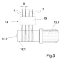
延伸装置10の供給側には、ガイド手段6と第1のゴデット11.1との間に、糸7において静電荷を生ぜしめる帯電手段14が設けられている。この帯電手段14は、本実施の形態では、電荷発生器15によって形成されており、この電荷発生器15によって生ぜしめられる電界は、電荷発生器15においてガイド手段6とゴデット11.1との間の糸走路において発生する。
On the supply side of the
帯電手段14の機能を説明するために、延伸装置10の供給側の部分図である図3を追加的に参照する。図3の図示から分かるように、糸7は互いに平行に並んで処理間隔をおいて延伸装置10に供給される。ガイド手段6によって決定された処理間隔は、図3では、Bで示されている。糸7が、第1のゴデット11.1の加熱されたゴデット周壁12.1の表面に乗り上げる前に、糸7は、電荷発生器15と、これによって生ぜしめられた電界を通過するので、糸7には静電気が帯電する。この静電気の帯電によって、静電荷はフィラメントストランドにおいて、フィラメントが互いに離反する反発力を、ひいては糸におけるフィラメントストランドの拡開を生ぜしめる力を発生させる。このようにして帯電された糸7は拡散されたフィラメント束をもってゴデット周壁12.1の表面に達する。これによって、ほぼすべてのフィラメントを、ゴデット11.1の加熱されたゴデット周壁12.1の周面に接触させかつ均一に加熱することが可能になる。
In order to explain the function of the charging means 14, reference is additionally made to FIG. 3, which is a partial view on the supply side of the stretching
糸7の相互の影響を回避するために、処理間隔Bは、2mm〜6mmの範囲における最小値に調節されている。処理間隔Bは、電荷発生器15の上流側に配置されたガイド手段6によって調節されている。
In order to avoid the mutual influence of the
図2における図示から分かるように、糸7は一緒に1つの糸群として、ゴデット周壁12.1〜12.4を介して案内される。糸7を延伸させるために、ゴデット11.2とゴデット11.3との間には、速度差が設定されているので、ゴデット11.2とゴデット11.3との間に本来の延伸ゾーンが形成されている。このとき、糸における電荷はほとんど弱化しないので、拡開効果は後続のゴデット11.2〜11.4にわたっても糸において維持されたままであることが観察された。これによって、糸におけるリラクゼーション処理のために必要な熱処理をも、極めて高い均一性で実施することができる。
As can be seen from the illustration in FIG. 2, the
図1及び図2における図示から分かるように、延伸装置10には、その走出側において直ぐ下に湿し装置16が対応配置されており、この湿し装置16によって糸7は、最後のゴデット周壁12.4からの走出直後に油剤(Praeparationsfluessigkeit)によって湿潤される。これによって好適に糸における放電が実施されるので、糸は例えば次いで巻成されてボビンを形成することができる。
As can be seen from the illustrations in FIGS. 1 and 2, the stretching
図1及び図2に示した本発明に係る装置の実施の形態では、合成マルチフィラメント糸を溶融紡糸しかつ延伸する本発明に係る方法は、4本の糸において平行に実施される。糸の数は一例である。基本的に本発明に係る方法及び本発明に係る装置は、多数の糸を同時に製造するのに適している。 In the embodiment of the device according to the invention shown in FIGS. 1 and 2, the method according to the invention for melt spinning and drawing synthetic multifilament yarns is carried out in parallel on four yarns. The number of yarns is an example. Basically, the method according to the invention and the device according to the invention are suitable for producing a large number of yarns simultaneously.
本発明に係る方法及び本発明に係る装置の機能を説明するために、図1及び図2には、糸の糸走路が略示されている。最初に、ポリマ溶融物から複数の繊細なフィラメントストランドが、紡糸ノズル2を通して押し出される。紡糸ノズル2毎に押し出された繊細なフィラメントストランドは、冷却後に集合糸ガイド5によってまとめられる。本実施の形態では、このような糸のまとめは、糸の湿潤なしに行われるので、糸は実質的に乾燥状態で紡糸装置1から引き出される。糸7の乾燥状態は、次いで行われる静電荷の帯電によって生ぜしめられる糸内部における拡開を得るのに特に好適である。
In order to explain the function of the method according to the invention and the device according to the invention, the thread runway of the yarn is shown schematically in FIGS. First, a plurality of delicate filament strands are extruded through the spinning
糸7は、1つの糸群として一緒に紡糸装置1から引き出され、まとめられた後でガイド手段6によって、後続の処理のために必要な処理間隔Bをおいて配置される。この処理間隔Bは、2mm〜6mmの範囲である。次いで糸7は帯電手段14によって静電気を帯電させられ、これによってフィラメント複合体においてフィラメントストランドを帯電によって拡開させることができる。静電気を帯電させられた糸7は、次いで直ぐに、加熱及び延伸のために、ゴデット11.1〜11.4の加熱されたゴデット周壁12.1〜12.4を介して案内される。延伸装置10から進出した後で、油剤によって糸の湿潤が行われる。これによって、フィラメントストランドの放電とフィラメントストランドの湿潤が行われるので、それぞれの糸において、フィラメントストランドはまとまる。
The
従って本発明に係る方法及び本発明に係る装置は、特に1本の糸を形成する複数のフィラメントストランドにおける熱処理及び延伸の均一化を可能にする。それぞれのフィラメントストランドは、主として温度と延伸とによって同一のポリマ構造を有するので、製造された糸は特に、着色に関して高い均一性を有するテキスタイルの使用分野に適している。 Therefore, the method according to the invention and the device according to the invention make it possible in particular to heat-treat and draw even in a plurality of filament strands forming a single yarn. Since each filament strand has the same polymer structure mainly due to temperature and drawing, the yarns produced are particularly suitable for textile applications with high uniformity with respect to coloration.
糸の合成フィラメントストランドに対する帯電は、図1及び図2に示した実施の形態によって、無接触式に、特に優しく行われるので、極めて繊細なフィラメントストランドを備えた糸を製造することもできる。また、図1及び図2に示した実施の形態とは異なり、糸が紡糸後にまず湿潤することによって糸結合部(Fadenschluss)を得ることも可能であり、糸は次いで電荷発生器の電界において静電荷を得ることができる。 The charging of the synthetic filament strands of the yarn is particularly gentle in a non-contact manner according to the embodiment shown in FIGS. 1 and 2, so that yarns with very fine filament strands can also be produced. In addition, unlike the embodiment shown in FIGS. 1 and 2, it is also possible to obtain a yarn joint (Fadenschluss) by first wetting the yarn after spinning, and the yarn is then statically applied in the electric field of the charge generator. Charge can be obtained.
糸を乾燥状態で紡糸装置から延伸装置に案内する場合には、さらに、糸結合部を渦動作用(Verwirbelung)によって形成することが通常である。このような装置は、別方向で見て図4及び図5に概略的に示されている。 In the case where the yarn is guided from the spinning device to the drawing device in a dry state, it is usual that the yarn coupling portion is further formed by vortex operation (Verwirbelung). Such a device is shown schematically in FIGS. 4 and 5 when viewed in another direction.
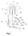
図4には、複数の合成マルチフィラメント糸を溶融紡糸しかつ延伸する本発明に係る装置の実施の形態が、正面図で示され、図5には側面図で示されている。本実施の形態は、図1及び図2に示した上述の実施の形態とほぼ同じであるので、以下においては相違点についてだけ説明し、その他については上述の記載を参照するものとする。なお以下の記載は、図4及び図5の両方に対するものである。 FIG. 4 shows a front view of an embodiment of the apparatus according to the present invention for melt spinning and drawing a plurality of synthetic multifilament yarns, and FIG. 5 shows a side view thereof. Since this embodiment is substantially the same as the above-described embodiment shown in FIGS. 1 and 2, only the differences will be described below, and the above description will be referred to for others. The following description is for both FIG. 4 and FIG.
図4及び図5に示した、本発明に係る装置の実施の形態では、糸は溶融紡糸後において延伸の前に渦動させられる。そのために冷却装置3と延伸装置10との間には、渦動装置20が設けられている。この渦動装置20は、糸毎に渦動ノズル21を有しており、この渦動ノズル21は、圧縮空気流を用いて糸7におけるフィラメントストランドを混合させる。
In the embodiment of the device according to the invention shown in FIGS. 4 and 5, the yarn is swirled after melt spinning and before drawing. For this purpose, a
しかしながら、糸7におけるフィラメントストランドのこのような交絡(Verflechtung)によって、フィラメントストランドの静電気の帯電が、糸を拡開させるのに不十分にしか作用し得ないような事態が生じ得る。このような交絡を可能な限り排除するために、図4及び図5に示した実施の形態では、帯電手段14は摩擦エレメント17によって形成されている。摩擦エレメント17は、ナイフ状のガイドエッジ18を有しており、このガイドエッジ18において糸7は接触状態で案内される。ガイドエッジ18は好ましくは、耐摩耗性のセラミック材料から形成されており、このとき、乾燥したフィラメントストランドには摩擦によって静電気が帯電させられる。糸7と摩擦エレメント17のガイドエッジ18との間における摩擦接触によって、予備渦動によって生ぜしめられた交絡を好適に最小にすることができる。このようにして糸7は、拡開された状態でゴデット11.1〜11.4のゴデット周壁12.1〜12.4を介して案内される。
However, such entanglement of the filament strands in the
このとき糸7を加熱しかつ延伸するための機能は、既に述べた実施の形態と同じである。
At this time, the function for heating and stretching the
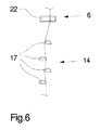
静電気の帯電のみならず、存在し得る交絡の解除を達成するために、複数の摩擦エレメントを糸走路に配置することも可能である。図6には、例えば図4及び図5に示した実施の形態において使用することができる、このような帯電手段の1つの実施の形態が示されている。図6には帯電手段14が、概略的に側面図で示されている。このとき、走入する糸7はそれぞれガイド手段6によって、後続の処理のために必要な処理間隔に合わせて配置される。ガイド手段6はここでは、糸7毎に各1つのガイド溝(略示のみ)を有する櫛歯糸ガイド22として形成されている。
It is also possible to arrange a plurality of friction elements on the yarn runway in order to achieve not only the electrostatic charge but also the release of possible confounding. FIG. 6 shows one embodiment of such a charging means that can be used, for example, in the embodiment shown in FIGS. FIG. 6 schematically shows the charging means 14 in a side view. At this time, the
櫛歯糸ガイド22の下において、帯電手段14は、複数の摩擦エレメント17によって形成されている。摩擦エレメント17は、半円形の横断面を有するエッジ糸ガイド23として形成されている。摩擦エレメント17は、互いにずらされて配置されており、このときエッジ糸ガイド23の丸く面取りされた形状は、走入する糸7に向けられ、つまり上側を向いている。糸の走出は、摩擦エレメント17において、エッジ糸ガイド23の比較的鋭い縁部を有するそれぞれの下側において行われる。エッジ糸ガイド23は、棒状に形成されているので、複数の糸を互いに平行に並べて案内することができる。エッジ糸ガイド23は、好ましくはセラミック材料から製造されている。
Under the comb tooth guide 22, the charging means 14 is formed by a plurality of
帯電手段14の図示の実施の形態では、全部で4つの摩擦エレメント17が、糸走路において相前後して配置されている。摩擦エレメント17の数は、基本的に任意である。しかしながら、摩擦エレメント17の数によって、糸に対する静電気の帯電に影響を及ぼすことができる。例えば、渦動されていない糸では摩擦エレメント17として、互いにずらして配置された比較的多数の湾曲した接触面を使用することが可能であり、これによって、フィラメントに静電気を帯電させることにより糸を拡開させることができる。
In the illustrated embodiment of the charging means 14, a total of four
図6に示した実施の形態では、摩擦エレメント17は通常、単数又は複数の支持体によって保持されている。このときまた、摩擦エレメント17の少なくとも一部を、糸の巻掛け程度を変化させるために可動に保持することも可能である。このようになっていると、フィラメントストランドにおいて生ぜしめられる摩擦を調節すること及び該摩擦に影響を及ぼすことが可能である。
In the embodiment shown in FIG. 6, the
図1及び図2並びに図4及び図5に示した、本発明に係る装置の実施の形態において、延伸装置のゴデットの配置形態及び数は例に過ぎない。基本的には、追加的に、加熱されない又は加熱される被駆動のゴデット又は加熱されない変向ローラを、延伸装置の内部に組み込むことが可能である。本発明に係る方法及び本発明に係る装置にとって重要なことは、加熱されたゴデット周壁の周囲において、糸のすべてのフィラメントストランドとの強力な糸接触を達成するために、静電気を帯電させられた糸を案内することである。 In the embodiment of the apparatus according to the present invention shown in FIGS. 1, 2, 4, and 5, the arrangement and number of godets in the stretching apparatus are merely examples. Basically, an unheated or heated driven godet or an unheated turning roller can additionally be incorporated inside the stretching device. Important for the method according to the invention and the device according to the invention is that the static electricity is charged in order to achieve strong yarn contact with all filament strands of the yarn around the heated godet peripheral wall. It is to guide the thread.
本発明に係る方法及び本発明に係る装置は、小さな番手又は大きな番手の合成マルチフィラメント糸を製造するのに適している。そしてテキスタイル・ヤーン及びテクニカル・ヤーンを共に好適に製造することができる。 The method according to the invention and the device according to the invention are suitable for producing a synthetic multifilament yarn having a small or large count. Both textile yarns and technical yarns can be suitably produced.
1 紡糸装置
2 紡糸ノズル
3 冷却装置
4 溶融物供給路
5 集合糸ガイド
6 ガイド手段
7 糸
8 紡糸ビーム
9 冷却ダクト
10 延伸装置
11.1〜11.4 ゴデット
12.1〜12.4 ゴデット周壁
13.1〜13.4 ゴデットモータ
14 帯電手段
15 電荷発生器
16 湿し装置
17 摩擦エレメント
18 ガイドエッジ
19 送風室
20 渦動装置
21 渦動ノズル
22 櫛歯糸ガイド
23 エッジ糸ガイド
DESCRIPTION OF
Claims (11)
糸に、複数のゴデットのうちの1つのゴデットの加熱されたゴデット周壁との接触前に、静電荷を与えており、
糸を紡糸後に乾燥状態で引き出しかつ延伸し、糸を延伸後に液体で湿潤することを特徴とする、複数のマルチフィラメント糸を溶融紡糸しかつ延伸する方法。 A method of melt spinning and drawing a plurality of synthetic multifilament yarns, wherein the yarns are juxtaposed in parallel to each other and extruded from the polymer melt, and after cooling the yarns, a plurality of heated godets of a plurality of driven godets In a circumferential wall, the godet circumferential wall is at least partially wrapped around, guided and heated, and the yarn is drawn by at least one speed difference between a plurality of godets,
The yarn is given an electrostatic charge before contact with the heated godet peripheral wall of one godet of the plurality of godets ,
A method of melt spinning and drawing a plurality of multifilament yarns, wherein the yarn is drawn and drawn in a dry state after spinning, and the yarn is wetted with a liquid after drawing.
延伸装置(10)の糸走入側に、糸(7)において静電荷を生ぜしめる帯電手段(14)が対応配置されており、前記延伸装置(10)の下流側に、糸(7)を液体によって湿潤可能な湿し装置(16)が配置されていることを特徴とする、複数のマルチフィラメント糸を溶融紡糸しかつ延伸する装置。 An apparatus for melt spinning and drawing a plurality of synthetic multifilament yarns, a spinning device (1) having a plurality of spinning nozzles (2) for extruding the plurality of multifilament yarns (7), and a yarn (7) A cooling device (3) for cooling the yarn and a drawing device (10) for drawing and drawing the yarn (7), the drawing device (10) comprising a plurality of heated godet peripheral walls (12.1). In a device having a plurality of driven godets (11.1 to 11.4) with
A charging means (14) for generating an electrostatic charge in the yarn (7) is arranged correspondingly on the yarn entry side of the drawing device (10), and the yarn (7) is arranged on the downstream side of the drawing device (10). A device for melt spinning and drawing a plurality of multifilament yarns, characterized in that a dampening device (16) that is wettable by a liquid is arranged .
Applications Claiming Priority (3)
| Application Number | Priority Date | Filing Date | Title |
|---|---|---|---|
| DE102013002992 | 2013-02-21 | ||
| DE102013002992.9 | 2013-02-21 | ||
| PCT/EP2014/052042 WO2014127981A1 (en) | 2013-02-21 | 2014-02-03 | Method and device for the melt-spinning and drawing of a plurality of multifilament threads |
Publications (2)
| Publication Number | Publication Date |
|---|---|
| JP2016511334A JP2016511334A (en) | 2016-04-14 |
| JP6355652B2 true JP6355652B2 (en) | 2018-07-11 |
Family
ID=50030323
Family Applications (1)
| Application Number | Title | Priority Date | Filing Date |
|---|---|---|---|
| JP2015558388A Expired - Fee Related JP6355652B2 (en) | 2013-02-21 | 2014-02-03 | Method and apparatus for melt spinning and drawing a plurality of multifilament yarns |
Country Status (4)
| Country | Link |
|---|---|
| JP (1) | JP6355652B2 (en) |
| CN (1) | CN105102699A (en) |
| DE (1) | DE112014000936A5 (en) |
| WO (1) | WO2014127981A1 (en) |
Families Citing this family (1)
| Publication number | Priority date | Publication date | Assignee | Title |
|---|---|---|---|---|
| DE102020114761A1 (en) * | 2019-06-19 | 2020-12-24 | Oerlikon Textile Gmbh & Co. Kg | Method and apparatus for melt spinning a variety of filaments |
Family Cites Families (16)
| Publication number | Priority date | Publication date | Assignee | Title |
|---|---|---|---|---|
| US3657871A (en) * | 1969-03-29 | 1972-04-25 | Toyo Boseki | Method and apparatus for spreading or dividing yarn, tow or the like |
| JPS4828004Y1 (en) * | 1970-04-17 | 1973-08-21 | ||
| GB1510553A (en) * | 1976-05-12 | 1978-05-10 | Standard Hose Ltd | Monofilament polytetrafluoroethylene fibre yarn |
| JPS53111014U (en) * | 1977-02-15 | 1978-09-05 | ||
| JPS5795306A (en) * | 1980-12-03 | 1982-06-14 | Teijin Ltd | Applying method of oiling agent in spinning at high speed |
| JPS59116406A (en) * | 1982-12-20 | 1984-07-05 | Toshio Moro | Unwinding rool for synthetic resin film |
| JPH01246412A (en) * | 1988-03-24 | 1989-10-02 | Chisso Corp | Production of crystalline polypropylene extremely thin yarn and crystalline polyolefin extremely thin yarn |
| DE4221160A1 (en) * | 1992-06-27 | 1993-01-21 | Thueringisches Inst Textil | Yarn mixing spreads out bands of yarns - for mixing in electrostatic field and gathering into mixed yarn |
| JP3643456B2 (en) * | 1996-12-20 | 2005-04-27 | 帝人ファイバー株式会社 | Method for producing polyester fiber |
| CN2299880Y (en) * | 1997-07-28 | 1998-12-09 | 慈溪市富华合成纤维联营厂 | Spinning drafting machine |
| DE102008039378A1 (en) | 2008-08-22 | 2010-02-25 | Oerlikon Textile Gmbh & Co. Kg | Method for melt-spinning, drawing, and winding multifilament to form fully drawn yarn, involves drawing filament bundle at specific drawing speed, preparing filament bundle using preparation fluid and winding thread into package |
| EP2283173B1 (en) * | 2008-05-23 | 2012-01-04 | Oerlikon Textile GmbH & Co. KG | Method for taking up and drawing a multifilament during melt-spinning, and apparatus for carrying out said method |
| EP2318577B1 (en) * | 2008-08-27 | 2012-01-18 | Oerlikon Textile GmbH & Co. KG | Method for melt spinning, stretching and winding a multifilament thread and device for carrying out the method |
| DE102010048017A1 (en) | 2009-11-17 | 2011-05-19 | Oerlikon Textile Gmbh & Co. Kg | Method for melt spinning and stretching of multiple synthetic threads i.e. industrial yarn, involves transferring individual filaments into filament bands, and guiding filament bands to guide surface of galette in parallel |
| DE102011109784A1 (en) * | 2011-08-08 | 2013-02-14 | Oerlikon Textile Gmbh & Co. Kg | Apparatus for melt spinning, stripping, stretching, relaxing and winding a synthetic thread |
| CN202465989U (en) * | 2012-02-27 | 2012-10-03 | 北京中丽制机工程技术有限公司 | Hot roller drawing type polytrimethylene terephthalate pre-oriented filament drawing and winding device |
-
2014
- 2014-02-03 JP JP2015558388A patent/JP6355652B2/en not_active Expired - Fee Related
- 2014-02-03 DE DE112014000936.9T patent/DE112014000936A5/en not_active Withdrawn
- 2014-02-03 CN CN201480009083.9A patent/CN105102699A/en active Pending
- 2014-02-03 WO PCT/EP2014/052042 patent/WO2014127981A1/en active Application Filing
Also Published As
| Publication number | Publication date |
|---|---|
| DE112014000936A5 (en) | 2015-11-26 |
| JP2016511334A (en) | 2016-04-14 |
| CN105102699A (en) | 2015-11-25 |
| WO2014127981A1 (en) | 2014-08-28 |
Similar Documents
| Publication | Publication Date | Title |
|---|---|---|
| JP5431460B2 (en) | Method for melt spinning, drawing and winding multifilament yarns and apparatus for carrying out this method | |
| JP6016919B2 (en) | Equipment for melt spinning, drawing, drawing, relaxing, and winding synthetic yarn | |
| JP5575238B2 (en) | Apparatus for carrying out a method of melt spinning, drawing and winding a multifilament yarn and a method of melt spinning, drawing and winding a multifilament yarn | |
| RU2556473C2 (en) | Device for spinning from melt, drawing and rolling of several complex threads | |
| US20130221559A1 (en) | Method For Producing A Multifilament Composite Thread And Melt Spinning Device | |
| JP6580120B2 (en) | Method and apparatus for producing fully drawn synthetic yarn | |
| CN105593416B (en) | Method and device for producing a fully drawn synthetic yarn | |
| JP6991225B2 (en) | Methods and equipment for cooling synthetic yarns | |
| JP2015529287A (en) | Melt spinning processing method and melt spinning processing apparatus for producing a wound yarn | |
| JP6355652B2 (en) | Method and apparatus for melt spinning and drawing a plurality of multifilament yarns | |
| CN106795652B (en) | For the method and apparatus by polyamide melt production polyfilament yarn | |
| CN107109704B (en) | Method and apparatus for producing a multifilament yarn | |
| CN100422410C (en) | Method and device for producing a low-shrinking smooth yarn | |
| CN110997991A (en) | Device for producing synthetic threads | |
| US11846044B2 (en) | Device and method for producing fancy yarns | |
| EP3545123B1 (en) | Device and method for manufacturing crimped textile yarn and cooling drum for such a device | |
| JP6440697B2 (en) | Texturing machine |
Legal Events
| Date | Code | Title | Description |
|---|---|---|---|
| A621 | Written request for application examination |
Free format text: JAPANESE INTERMEDIATE CODE: A621 Effective date: 20161024 |
|
| A977 | Report on retrieval |
Free format text: JAPANESE INTERMEDIATE CODE: A971007 Effective date: 20170922 |
|
| A131 | Notification of reasons for refusal |
Free format text: JAPANESE INTERMEDIATE CODE: A131 Effective date: 20171002 |
|
| A601 | Written request for extension of time |
Free format text: JAPANESE INTERMEDIATE CODE: A601 Effective date: 20171221 |
|
| A521 | Request for written amendment filed |
Free format text: JAPANESE INTERMEDIATE CODE: A523 Effective date: 20180202 |
|
| TRDD | Decision of grant or rejection written | ||
| A01 | Written decision to grant a patent or to grant a registration (utility model) |
Free format text: JAPANESE INTERMEDIATE CODE: A01 Effective date: 20180514 |
|
| A61 | First payment of annual fees (during grant procedure) |
Free format text: JAPANESE INTERMEDIATE CODE: A61 Effective date: 20180612 |
|
| R150 | Certificate of patent or registration of utility model |
Ref document number: 6355652 Country of ref document: JP Free format text: JAPANESE INTERMEDIATE CODE: R150 |
|
| LAPS | Cancellation because of no payment of annual fees |