JP6355366B2 - Pinch valve - Google Patents

Pinch valve Download PDF

Info

Publication number
JP6355366B2
JP6355366B2 JP2014045566A JP2014045566A JP6355366B2 JP 6355366 B2 JP6355366 B2 JP 6355366B2 JP 2014045566 A JP2014045566 A JP 2014045566A JP 2014045566 A JP2014045566 A JP 2014045566A JP 6355366 B2 JP6355366 B2 JP 6355366B2
Authority
JP
Japan
Prior art keywords
tubular body
tube
pinch valve
restoration
flow path
Prior art date
Legal status (The legal status is an assumption and is not a legal conclusion. Google has not performed a legal analysis and makes no representation as to the accuracy of the status listed.)
Active
Application number
JP2014045566A
Other languages
Japanese (ja)
Other versions
JP2015169292A (en
JP2015169292A5 (en
Inventor
真哉 木村
真哉 木村
田中 啓一
啓一 田中
Current Assignee (The listed assignees may be inaccurate. Google has not performed a legal analysis and makes no representation or warranty as to the accuracy of the list.)
1/1ASAHI YUKIZAI CORPORATION
Original Assignee
1/1ASAHI YUKIZAI CORPORATION
Priority date (The priority date is an assumption and is not a legal conclusion. Google has not performed a legal analysis and makes no representation as to the accuracy of the date listed.)
Filing date
Publication date
Application filed by 1/1ASAHI YUKIZAI CORPORATION filed Critical 1/1ASAHI YUKIZAI CORPORATION
Priority to JP2014045566A priority Critical patent/JP6355366B2/en
Publication of JP2015169292A publication Critical patent/JP2015169292A/en
Publication of JP2015169292A5 publication Critical patent/JP2015169292A5/ja
Application granted granted Critical
Publication of JP6355366B2 publication Critical patent/JP6355366B2/en
Active legal-status Critical Current
Anticipated expiration legal-status Critical

Links

Images

Description

本発明は、化学工場、半導体製造、食品、バイオなどの各種産業分野における各種流体を移送するときに用いられるピンチバルブに関する。   The present invention relates to a pinch valve used for transferring various fluids in various industrial fields such as chemical factories, semiconductor manufacturing, food, and biotechnology.

従来、各種流体を移送する管体を内部に有するピンチバルブとして、図8に示すようなピンチバルブ100が知られている。このピンチバルブ100は、本体101の内部に、流路を形成するチューブ102を、弁箱内に、モータ103を、モータ103の下方に、モータ103の正逆駆動により上下動する昇降体104を、昇降体の下端に押止材105を有する。チューブ102はゴムなどの弾性材料によって構成され、昇降体104の上下動に伴って押止材105が上下動し、チューブ102を径方向に押圧または押圧力を解放して流路を開閉する。   Conventionally, a pinch valve 100 as shown in FIG. 8 is known as a pinch valve having a pipe body for transferring various fluids therein. This pinch valve 100 includes a tube 102 that forms a flow path inside a main body 101, a motor 103 in a valve box, and a lifting body 104 that moves up and down by forward / reverse driving of the motor 103 below the motor 103. The holding member 105 is provided at the lower end of the lifting body. The tube 102 is made of an elastic material such as rubber, and the holding member 105 moves up and down as the elevating body 104 moves up and down, and presses the tube 102 in the radial direction or releases the pressing force to open and close the flow path.

しかしながら、押止材105によってチューブ102内の流路を完全に閉状態にするためには、かなり大きな押圧力が必要となる。このため、押圧力によって流路を閉じた状態、すなわちチューブ102の内周面を接触させた状態で長期間放置すると、押圧力を解放したときに、チューブ102が押し潰された状態から復元しなくなったり、復元するのに時間がかかったりするおそれがある。チューブ102が復元しなかったり、復元するのに時間がかかったりすると、このピンチバルブ100は所定の流量を確保することができなくなるおそれがある。   However, in order to completely close the flow path in the tube 102 by the pressing member 105, a considerably large pressing force is required. Therefore, if the flow path is closed by the pressing force, that is, if the inner peripheral surface of the tube 102 is kept in contact with the tube 102 for a long time, the tube 102 is restored from the crushed state when the pressing force is released. It may disappear or take time to restore. If the tube 102 does not recover or it takes time to recover, the pinch valve 100 may not be able to ensure a predetermined flow rate.

このようなチューブ102が押し潰された状態から復元しなくなったり、復元するのに時間がかかったりすることを防止するようにしたピンチバルブとして、図9に示すようなピンチバルブ200が知られている(例えば特許文献1参照)。このピンチバルブ200は、図9に示すように、ホース201の両側にガイド孔202が形成された一対の可動アーム203が配置されており、可動アーム203はホース201を押圧するプッシャー204とリンク205を介して連結されている。プッシャー204とリンク205はボルトによって一体的に固定されている。一方、可動アーム203とリンク205はガイド孔202を自由に移動するガイドピン206によって摺動自在に連結されている。プッシャー204がホース201を押圧してホース201の内周面を密着させる閉操作時には、可動アーム203はプッシャー204に連動してホース201から離れる方向に駆動される。また、プッシャー204がホース201の押圧する力を解放する開操作時には、プッシャー204がホース201の開方向に移動する動作に連動して、可動アーム203はホース201を両側から挟む方向に駆動される。このとき、可動アーム203がホース201の両側からホース201を挟むことによって、ホース201を元の形状に復元させることができる。   A pinch valve 200 as shown in FIG. 9 is known as a pinch valve that prevents the tube 102 from being restored from being crushed or taking time to restore. (For example, refer to Patent Document 1). As shown in FIG. 9, the pinch valve 200 includes a pair of movable arms 203 in which guide holes 202 are formed on both sides of the hose 201, and the movable arm 203 includes a pusher 204 that presses the hose 201 and a link 205. It is connected through. The pusher 204 and the link 205 are integrally fixed by bolts. On the other hand, the movable arm 203 and the link 205 are slidably connected by a guide pin 206 that freely moves in the guide hole 202. When the pusher 204 presses the hose 201 to close the inner peripheral surface of the hose 201, the movable arm 203 is driven in a direction away from the hose 201 in conjunction with the pusher 204. Further, when the pusher 204 is opened to release the pressing force of the hose 201, the movable arm 203 is driven in a direction to sandwich the hose 201 from both sides in conjunction with the movement of the pusher 204 in the opening direction of the hose 201. . At this time, when the movable arm 203 sandwiches the hose 201 from both sides of the hose 201, the hose 201 can be restored to its original shape.

特開2003−90446号公報JP 2003-90446 A

しかしながら、上記特許文献1記載のピンチバルブでは、それぞれ異なる部品であるプッシャー204と可動アーム203とを連動して作動させるために、プッシャー204と可動アーム203との間にリンク205を介在させている。この構成は部品点数が増加するだけでなく、一対の可動アーム203を左右対称に作動させホース201に同時に作用させるために、微妙な調整が必要となることから組立作業に時間と熟練を必要とする。また、プッシャー204と可動アーム203とが連動して作動することから、部品の腐食や連結部の緩みなどによって、可動アーム203の作動が左右対称でなくなるなどの不具合が生じるおそれがある。可動アーム203が左右対称に作動しないと、ホース201の変形や弾性復元する時間の遅れなどが生じるおそれがある。また、ピンチバルブ内部に多くの部品が連動するように配置されていることから、ピンチバルブが大型化しやすい。また、プッシャー204、可動アーム203、リンク205からなる可動部がピンチバルブ内部に配置されることから、不具合が生じても、不具合を認識するのに時間がかかるおそれがある。   However, in the pinch valve described in Patent Document 1, a link 205 is interposed between the pusher 204 and the movable arm 203 in order to operate the pusher 204 and the movable arm 203, which are different parts. . This configuration not only increases the number of parts, but also requires time and skill in assembly work because fine adjustment is required to operate the pair of movable arms 203 symmetrically and simultaneously act on the hose 201. To do. In addition, since the pusher 204 and the movable arm 203 operate in conjunction with each other, there is a possibility that problems such as the operation of the movable arm 203 becoming non-symmetrical may occur due to corrosion of parts or loosening of the connecting portion. If the movable arm 203 does not operate symmetrically, the hose 201 may be deformed or may be delayed in elastic recovery. In addition, since many components are arranged inside the pinch valve so as to be interlocked with each other, the pinch valve is easily increased in size. In addition, since the movable portion including the pusher 204, the movable arm 203, and the link 205 is disposed inside the pinch valve, it may take time to recognize the malfunction even if a malfunction occurs.

本発明の目的は、作動不良が少なく、押圧された管体を安定して復元することができるとともに、コンパクトなピンチバルブを提供することである。   An object of the present invention is to provide a compact pinch valve with few malfunctions and capable of stably restoring a pressed tube.

本発明の一態様によれば、本体と、弾性を有し内部に流路を有するとともに本体に収容される管体と、管体を押圧しまたは押圧を解除して流路を閉状態または開状態にする押圧手段と、管体が押圧された状態から全開状態に復元する動作を補助する復元補助手段と、を備えるピンチバルブにおいて、復元補助手段は、押圧手段が管体を押圧したときに、押圧され変形した管体の少なくとも一部を受容する凹面を有する管体受容部と、管体の復元を補助するように構成された補助部であって、凹面から連続的に隆起するとともに、押圧手段が管体の押圧を解除したときに押圧手段の押圧方向及び流路軸線方向と直交する方向に管体を押圧する、凸面を有する補助部と、押圧手段に一体的に固定される固定部と、を有し、復元補助手段が押圧手段と同一行程で移動する、ピンチバルブが提供される。
According to one embodiment of the present invention, a main body, a tube having elasticity and having a flow path therein and accommodated in the main body, and pressing or releasing the pressure to close or open the flow path In a pinch valve comprising: a pressing means for setting a state; and a restoring auxiliary means for assisting an operation of restoring the tube body from the pressed state to the fully open state. A tube receiving portion having a concave surface for receiving at least a part of the pressed and deformed tube, and an auxiliary portion configured to assist the restoration of the tube, and continuously raised from the concave surface, An auxiliary portion having a convex surface that presses the tubular body in a direction orthogonal to the pressing direction of the pressing means and the flow axis direction when the pressing means releases the pressing of the tubular body, and a fixing that is integrally fixed to the pressing means. The restoration assisting means is a pressing means. Move at the same stroke, the pinch valve is provided.

すなわち、本発明の一態様では、復元補助手段が上記特許文献1に記載の発明とは異なり可動部を含まず、押圧手段と同一行程で移動するように押圧手段に一体的に固定されているので、復元補助手段と押圧手段との相対的な位置関係が維持された状態で管体の復元を補助することができる。すなわち、復元補助手段と押圧手段は両手段の間に、両手段を相対的に移動させるための可動部を設けることなく連結されているので、作動不良が少なく、安定して管体の復元を補助することができる。また、復元補助手段の中に可動部が存在せず、復元補助手段と押圧手段の間にも可動部が存在しないことから、部品点数を少なくすることができるだけでなく、組立作業を簡単にすることができる。また、復元補助手段が押圧手段と同一行程で移動することから、管体の復元を補助するのに必要な空間を小さくすることができ、ピンチバルブの大型化を防ぐことができる。ここで、上記可動部とは、複数の部品がギアやカムなどによって、押圧手段から復元補助手段へ駆動力を伝達する作用をする部分のことである。
That is, in one aspect of the present invention, unlike the invention described in Patent Document 1, the restoration assisting unit does not include a movable part and is integrally fixed to the pressing unit so as to move in the same stroke as the pressing unit. Therefore, it is possible to assist the restoration of the tubular body while maintaining the relative positional relationship between the restoration assisting means and the pressing means. That is, since the restoration assisting means and the pressing means are connected between the two means without providing a movable part for relatively moving both means, there is less malfunction and stable restoration of the tube body. Can assist. Further, since there is no movable part in the restoration assisting means and there is no movable part between the restoration assisting means and the pressing means, not only the number of parts can be reduced, but also the assembly work is simplified. be able to. In addition, since the restoration assisting means moves in the same stroke as the pressing means, the space necessary for assisting the restoration of the tubular body can be reduced, and an increase in the size of the pinch valve can be prevented. Here, the movable part is a part in which a plurality of parts act to transmit driving force from the pressing means to the restoration assisting means by gears or cams.

本発明の一態様によれば、本体は管体を収容する管体収容部と、管体収容部に連通するとともに全閉状態において復元補助手段を収容する復元補助手段収容部とを備え、復元補助手段収容部の深さが管体収容部の深さより深い、ピンチバルブが提供される。
According to one aspect of the present invention, the body includes a tubular body accommodating portion for accommodating the tube, and the restoration assisting means accommodating portion for accommodating the restore aid with Te fully closed odor communicating with the tube receiving portion A pinch valve is provided in which the depth of the restoration assisting means accommodation portion is deeper than the depth of the tube body accommodation portion .

すなわち、本発明の一態様では、復元補助手段に管体受容部と補助部が設けられるとともに、本体に管体収容部と復元補助手段収容部が設けられたことから、可動部を含まない簡単な構成で管体の復元を補助することができる。
That is, according to one aspect of the present invention , since the tube receiving portion and the auxiliary portion are provided in the restoration assisting means, and the tube body accommodating portion and the restoration assisting device accommodating portion are provided in the main body, the movable portion is not included. The reconstruction of the tube can be assisted with a simple configuration.

本発明の一態様によれば、補助部の流路軸線方向の長さが全閉状態の管体の内周面が接触している部分の流路軸線方向の長さよりも長いピンチバルブが提供される。
According to one aspect of the present invention, the length of the flow path axial direction of the auxiliary section is longer than the length of the flow path axial direction of the portion in contact with the inner peripheral surface of the tube in the fully closed state, the pinch valve Is provided.

すなわち、本発明の一態様では、補助部の流路軸線方向の長さが全閉状態の管体の内周面が互いに接触している部分の流路軸線方向の長さよりも長く形成されていることから、補助部が管体の変形の大きい部分に対して広い範囲で接触することができ、安定して管体の復元を補助することができる。
That is, in one aspect of the present invention, the length in the flow path axis direction of the auxiliary portion is formed to be longer than the length in the flow path axis direction of the portion where the inner peripheral surfaces of the fully closed tubular bodies are in contact with each other. Therefore, the auxiliary portion can come into contact with the large deformation portion of the tubular body in a wide range and can stably assist the restoration of the tubular body.

本発明の一態様によれば、復元補助手段が管体の両側に対向して配置され、管体が全開状態に近づくにつれて、補助部の管体に接触している部分同士の間隔が狭くなるように、補助部の管体側の凸面が傾斜面または曲面を含む、ピンチバルブが提供される。
According to one aspect of the present invention, restore the auxiliary means is disposed opposite to both sides of the tube, as the tube approaches the fully open state, the interval portions between which is in contact with the tubular body of the auxiliary section to be narrower, convex surface of the auxiliary portion of the tube side comprises an inclined surface or a curved surface, the pinch valve is provided.

すなわち、本発明の一態様では、管体が全開状態に近づくにつれて、補助部の管体に接触している部分同士の間隔が狭くなるように、補助部の管体側の凸面が傾斜面または曲面で形成されていることから、補助部の管体に接触している部分同士の間隔を管体の開度に応じて適切な間隔にすることができ、管体に無理な力を加えることなく管体の復元を補助することができる。
That is, in one aspect of the present invention, the convex surface on the tube side of the auxiliary portion is inclined or curved so that the interval between the portions in contact with the tube of the auxiliary portion becomes narrower as the tube approaches the fully open state. Therefore, the interval between the parts in contact with the tube of the auxiliary portion can be set to an appropriate interval according to the opening of the tube, without applying an excessive force to the tube. The restoration of the tube can be assisted.

本発明の一態様によれば、復元補助手段が管体の両側に対向して配置され、全開状態における補助部の管体に接触している部分同士の間隔が、管体の外径よりも僅かに狭いピンチバルブが提供される。
According to one aspect of the present invention, restore the auxiliary means is disposed opposite to both sides of the tube, the spacing portion between in contact with the tubular body of the auxiliary unit that put in the fully open state, the tubular body slightly narrower than the outer diameter, the pinch valve is provided.

すなわち、本発明の一態様では、全開状態における補助部の管体に接触している部分同士の間隔が、管体の外径よりも僅かに狭く形成されていることから、管体が全開状態においても管体の復元を補助する力を受けることができ、管体が確実に全開状態になるように管体の復元を補助することができる。
That is, in one aspect of the present invention, since the interval between the portions each other in contact with the tubular body of the auxiliary unit that put in the fully open state, is slightly smaller than the outer diameter of the tube, the tube Even in the fully open state, it is possible to receive a force that assists the restoration of the tubular body, and it is possible to assist the restoration of the tubular body so that the tubular body is surely opened.

本発明の一態様によれば、補助部の少なくとも管体に接触する面の静摩擦係数μが0.01≦μ≦0.6であるピンチバルブが提供される。
According to one aspect of the present invention, the static friction coefficient of the surface in contact with the least well pipe of the auxiliary portion mu is 0.01 ≦ μ ≦ 0.6, the pinch valve is provided.

すなわち、本発明の一態様では、補助部の静摩擦係数μが0.01≦μ≦0.6であることから、補助部が管体の復元を補助するときに管体の補助部と接触する面の摩耗を防ぐことができる。
That is, in one aspect of the present invention, since the static friction coefficient μ of the auxiliary portion is 0.01 ≦ μ ≦ 0.6, the auxiliary portion contacts the auxiliary portion of the tubular body when assisting the restoration of the tubular body. Surface wear can be prevented.

本発明の一態様によれば、押圧手段が流路を全開状態および全閉状態の二段階の状態にするように駆動され、押圧手段より管体の流路の上流側若しくは管体の下側又は管体を挟んだ反対側、管体を押圧して流路の開度を任意に調整する調整用押圧手段が装着されているピンチバルブが提供される。
According to one aspect of the present invention, is driven to the two-stage fully opened state and the fully closed state flow path the pressing means, the tube from the pressing means of the flow path of the upstream or tube on the opposite side across the bottom or tube, adjusting pressing means arbitrarily adjusts the opening degree of the flow path by pressing the tubular body is mounted, the pinch valve is provided.

すなわち、本発明の一態様では、ひとつの本体の上流側の部分に流量を調整するための押圧手段を配置し、下流側の部分に流路を開閉するための押圧手段を配置したことから、全閉状態から流量調整状態にするときに短時間で流量を安定させることができる。
That is, in one aspect of the present invention, the pressing means for adjusting the flow rate is arranged in the upstream part of one main body, and the pressing means for opening and closing the flow path is arranged in the downstream part. When changing from the fully closed state to the flow rate adjustment state, the flow rate can be stabilized in a short time.

本発明の一態様によれば、復元補助手段が、復元補助手段の中に可動部を含まず、押圧手段と同一行程で移動するように押圧手段に一体的に固定されているので、作動不良が少なく、押圧されていた管体を安定して復元することができるとともに、コンパクトなピンチバルブを提供することができる。
According to one aspect of the present invention, the restoration assisting unit does not include a movable part in the restoration assisting unit and is integrally fixed to the pressing unit so as to move in the same stroke as the pressing unit. Therefore, the pressed tube can be stably restored and a compact pinch valve can be provided.

本発明の第一の実施の形態に係るピンチバルブの閉状態を示す縦断面図である。It is a longitudinal cross-sectional view which shows the closed state of the pinch valve which concerns on 1st embodiment of this invention. 本発明の第一の実施の形態に係るピンチバルブの開状態を示す縦断面図である。It is a longitudinal cross-sectional view which shows the open state of the pinch valve which concerns on 1st embodiment of this invention. 本発明の第一の実施の形態に係るピンチバルブの開状態を示す流路軸線と直行する方向からの縦断面図である。It is a longitudinal cross-sectional view from the direction orthogonal to the flow-path axis which shows the open state of the pinch valve which concerns on 1st embodiment of this invention. 図1〜3のピストンと復元補助部材の外観斜視図である。It is an external appearance perspective view of the piston of FIG. (a)は本発明の第一の実施の形態に係るピンチバルブの駆動部の組み立て手順を示す縦断面図である。(b)は本発明の第一の実施の形態に係るピンチバルブの駆動部の組み立て手順を示す他の縦断面図である。(A) is a longitudinal cross-sectional view which shows the assembly procedure of the drive part of the pinch valve which concerns on 1st embodiment of this invention. (B) is another longitudinal cross-sectional view which shows the assembly procedure of the drive part of the pinch valve which concerns on 1st embodiment of this invention. 本発明の第二の実施の形態に係るピンチバルブの概略構成を示す流路軸線と直行する方向からの縦断面図である。It is a longitudinal cross-sectional view from the direction orthogonal to the flow-path axis line which shows schematic structure of the pinch valve which concerns on 2nd embodiment of this invention. 本発明の第三の実施の形態に係るピンチバルブの概略構成を示す縦断面図である。It is a longitudinal cross-sectional view which shows schematic structure of the pinch valve which concerns on 3rd embodiment of this invention. 従来のピンチバルブを示す縦断面図である。It is a longitudinal cross-sectional view which shows the conventional pinch valve. 従来の他のピンチバルブを示す縦断面図である。It is a longitudinal cross-sectional view which shows the other conventional pinch valve.

―第一の実施の形態―
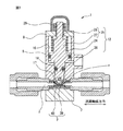
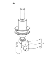
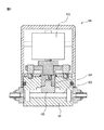
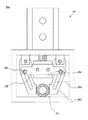
以下、図1〜図5を参照して、本発明によるピンチバルブの第一の実施の形態について説明する。図1はピンチバルブの閉状態を示す縦断面図であり、図2、3はピンチバルブの開状態を示す縦断面図であり、図4はピンチバルブの構成部品の外観斜視図であり、図5はピンチバルブの構成部品の組み立て手順を示す縦断面図である。
―First embodiment―
A first embodiment of a pinch valve according to the present invention will be described below with reference to FIGS. 1 is a longitudinal sectional view showing a closed state of a pinch valve, FIGS. 2 and 3 are longitudinal sectional views showing an opened state of the pinch valve, and FIG. 4 is an external perspective view of components of the pinch valve. 5 is a longitudinal sectional view showing the assembly procedure of the components of the pinch valve.

第一の実施の形態に係るピンチバルブ1は、内部に開閉可能な流路2を有する管体3と、管体3を径方向に押圧して流路2を開閉させる挟圧子4と、挟圧子4と一体的に固定され管体3の閉状態から開状態への復元を補助する復元補助部材5と、挟圧子4を駆動する駆動部6とを備える。ここで、押圧手段とは挟圧子4および挟圧子4と一体化している部材を指している。また、復元補助手段とは復元補助部材5を指している。第1の実施の形態では、復元補助部材5が特徴的な構成である。   The pinch valve 1 according to the first embodiment includes a tubular body 3 having a flow path 2 that can be opened and closed inside, a pinching element 4 that presses the tubular body 3 in a radial direction to open and close the flow path 2, A restoration assisting member 5 that is fixed integrally with the indenter 4 and assists restoration of the tubular body 3 from the closed state to the opened state, and a drive unit 6 that drives the pinch indenter 4 are provided. Here, the pressing means refers to the sandwiching element 4 and a member integrated with the sandwiching element 4. Further, the restoration assistance means refers to the restoration assistance member 5. In the first embodiment, the restoration assisting member 5 has a characteristic configuration.

第一の実施の形態において、ピンチバルブ1は、本体7と、管体3の両端部に取り付けられる継手11とを有する。また、駆動部6は、本体7の上部に固定されるシリンダー本体8と、シリンダー本体8の上端部に取り付けられるシリンダー蓋9と、シリンダー蓋9に取り付けられるカバー10と、外部から供給される圧縮空気によってシリンダー本体8内で昇降するピストン12とを有する。   In the first embodiment, the pinch valve 1 includes a main body 7 and joints 11 attached to both ends of the tube body 3. The drive unit 6 includes a cylinder body 8 fixed to the upper portion of the body 7, a cylinder lid 9 attached to the upper end of the cylinder body 8, a cover 10 attached to the cylinder lid 9, and compression supplied from the outside. And a piston 12 that moves up and down in the cylinder body 8 by air.

第一の実施の形態において、本体7はポリフェニレンサルファイド(以下、PPSと記す)製である。図1〜3に示すように、本体7は略四角柱形状に形成されている。本体7の上端面には、シリンダー本体8がボルト・ナット(図示せず)で接合固定される。本体7には、管体3を収容する収容部である管体収容部13と、復元補助部材5を収容する収容部である復元補助部材収容部14とを備える第一収容部15が形成されている。管体収容部13は本体7の上面の流路軸線上に形成され、復元補助部材収容部14は、管体3を隔てて管体収容部13の両側にこれと連通するように形成されている。また、図3に示すように、復元補助部材収容部14の深さは管体収容部13の深さよりも深く形成されている。   In the first embodiment, the main body 7 is made of polyphenylene sulfide (hereinafter referred to as PPS). As shown in FIGS. 1-3, the main body 7 is formed in a substantially quadrangular prism shape. A cylinder body 8 is joined and fixed to the upper end surface of the body 7 with bolts and nuts (not shown). The main body 7 is formed with a first housing portion 15 including a tube body housing portion 13 which is a housing portion for housing the tube body 3 and a restoration assisting member housing portion 14 which is a housing portion for housing the restoration assisting member 5. ing. The tubular body accommodating portion 13 is formed on the flow path axis on the upper surface of the main body 7, and the restoration assisting member accommodating portion 14 is formed so as to communicate with both sides of the tubular body accommodating portion 13 across the tubular body 3. Yes. As shown in FIG. 3, the depth of the restoration assisting member housing portion 14 is formed deeper than the depth of the tube body housing portion 13.

第一の実施の形態において、シリンダー本体8はPPS製である。図1〜3に示すように、シリンダー本体8は略四角柱形状に形成されている。シリンダー本体8の上部には、円筒状空間を形成するシリンダー部16が形成されている。シリンダー部16の上端部には、中央に貫通孔が形成された板状のシリンダー蓋9が固定されている。シリンダー本体8の下部には、ピストン12の軸部26の下部と復元補助部材5とを収容する第二収容部17が形成されている。シリンダー本体8の中間部には、シリンダー部16と第二収容部17とを連通し、ピストン12の軸部26が貫通する貫通孔18が形成されている。貫通孔18の上方には、シリンダー部16の内周面及び底面とシリンダー部16に組み込まれたピストン12の円盤部24下端面とによって第一の空間部19が形成される。さらに、ピストン12の上方には、シリンダー部16の内周面とシリンダー蓋9の下端面とピストン12の円盤部24上端面とによって第二の空間部20が形成されている。第二の空間部20にはピストン12を管体3方向に付勢するバネ22が配置されている。シリンダー本体8の周側面には第一の空間部19に連通する空気孔21が設けられ、空気孔21を介して各空間部19に圧縮空気供給機器など(図示せず)から圧縮空気が供給される。また、シリンダー本体8の流路軸線と直交する方向の両方の側面には、挟圧子4と復元補助部材5とを一体的に固定するための固定ピン37を通過させるための貫通孔23が形成されている。   In the first embodiment, the cylinder body 8 is made of PPS. As shown in FIGS. 1-3, the cylinder main body 8 is formed in the substantially square pillar shape. A cylinder portion 16 that forms a cylindrical space is formed on the upper portion of the cylinder body 8. A plate-like cylinder lid 9 having a through hole formed in the center is fixed to the upper end portion of the cylinder portion 16. A second accommodating portion 17 that accommodates the lower portion of the shaft portion 26 of the piston 12 and the restoration assisting member 5 is formed in the lower portion of the cylinder body 8. A through-hole 18 is formed in the middle portion of the cylinder body 8 so as to communicate the cylinder portion 16 and the second housing portion 17 and through which the shaft portion 26 of the piston 12 passes. Above the through hole 18, a first space portion 19 is formed by the inner peripheral surface and bottom surface of the cylinder portion 16 and the lower end surface of the disc portion 24 of the piston 12 incorporated in the cylinder portion 16. Further, a second space portion 20 is formed above the piston 12 by the inner peripheral surface of the cylinder portion 16, the lower end surface of the cylinder lid 9, and the upper end surface of the disk portion 24 of the piston 12. A spring 22 that urges the piston 12 toward the tube body 3 is disposed in the second space portion 20. An air hole 21 communicating with the first space portion 19 is provided on the peripheral side surface of the cylinder body 8, and compressed air is supplied to each space portion 19 through the air hole 21 from a compressed air supply device (not shown). Is done. Further, on both side surfaces of the cylinder body 8 in the direction orthogonal to the flow path axis, a through hole 23 for allowing a fixing pin 37 for fixing the sandwiching element 4 and the restoration assisting member 5 integrally is formed. Has been.

第一の実施の形態において、ピストン12はステンレススチール(以下、SUSと記す)製である。図1〜3に示すように、円盤部24と開度制御部25と軸部26とを備えている。円盤部24は円盤形状で周側面にOリングが装着され、シリンダー部16の内周面に上下動可能かつ密封状態に嵌合されている。開度制御部25は円盤部24の中央から垂直に突出して設けられ、第一開度制御部27と第二開度制御部28を備えている。第一開度制御部27は円柱形状で円盤部24の上面中央から垂直に突出し、第二開度制御部28は第一開度制御部27より小径の円柱形状で第一開度制御部27の上端中央より垂直に突出している。第二開度制御部28はシリンダー蓋9の中央部に設けられた貫通孔を貫通し、先端部にはナット29が螺合される雄ネジ部が形成されている。軸部26は円盤部24の下面中央から突出して設けられ、シリンダー本体8に設けられた貫通孔18を密封状態で貫通している。軸部26の下部の流路軸線方向の側面にはピストン12の回動を防ぐために面取部(図示せず)が形成され、軸部26の先端部の流路軸線方向の側面には、当該先端部が流路軸線方向に狭くなるようにテーパーが形成されている。また、軸部26の先端部には挟圧子4が設けられている。   In the first embodiment, the piston 12 is made of stainless steel (hereinafter referred to as SUS). As shown in FIGS. 1-3, the disk part 24, the opening degree control part 25, and the axial part 26 are provided. The disk portion 24 is a disk shape, and an O-ring is mounted on the peripheral side surface thereof. The disk portion 24 is fitted to the inner peripheral surface of the cylinder portion 16 so as to be vertically movable and sealed. The opening degree control unit 25 is provided so as to protrude vertically from the center of the disk part 24, and includes a first opening degree control unit 27 and a second opening degree control unit 28. The first opening degree control unit 27 has a cylindrical shape and protrudes vertically from the center of the upper surface of the disk part 24, and the second opening degree control unit 28 has a columnar shape with a smaller diameter than the first opening degree control unit 27 and the first opening degree control unit 27. It protrudes vertically from the center of the top of the. The second opening degree control unit 28 passes through a through hole provided in the center portion of the cylinder lid 9, and a male screw portion into which a nut 29 is screwed is formed at the tip portion. The shaft portion 26 is provided so as to protrude from the center of the lower surface of the disk portion 24 and penetrates the through hole 18 provided in the cylinder body 8 in a sealed state. A chamfered portion (not shown) is formed on the side surface of the lower portion of the shaft portion 26 in the flow path axial direction to prevent the piston 12 from rotating, and on the side surface of the tip portion of the shaft portion 26 in the flow passage axial direction, A taper is formed so that the tip end portion becomes narrower in the flow path axis direction. Further, the pinch 4 is provided at the tip of the shaft portion 26.

挟圧子4はピストン12の軸部26の先端部に設けられている。図1〜4に示すように、挟圧子4の管体3を押圧する部分は、流路軸線方向に直交する方向に長手方向を有する断面略矩形の流路軸線方向の両端角部にRを付した形状、すなわちかまぼこ形状に形成されている。挟圧子4の流路軸線と直交する側面同士間に貫通孔30が形成されている。挟圧子4の流路軸線と直交する側面には、一対の復元補助部材5が挟圧子4を挟持するように固定されている。第一の実施の形態では、挟圧子4はピストン12と一体に形成されているが、挟圧子4がピストン12と別体に形成され、挟圧子4とピストン12とを接着や螺合などの手段で一体的に固定してもよい。   The pinch 4 is provided at the tip of the shaft portion 26 of the piston 12. As shown in FIGS. 1 to 4, the portion that presses the tube body 3 of the pincer 4 has R at both end corners in the channel axial direction having a substantially rectangular cross section having a longitudinal direction in a direction orthogonal to the channel axial direction. It is formed in an attached shape, that is, a kamaboko shape. A through hole 30 is formed between side surfaces orthogonal to the flow path axis of the pinch element 4. A pair of restoration assisting members 5 are fixed to the side surface of the pinch 4 perpendicular to the flow path axis so as to hold the pinch 4. In the first embodiment, the sandwiching element 4 is formed integrally with the piston 12. However, the sandwiching element 4 is formed separately from the piston 12, and the sandwiching element 4 and the piston 12 are bonded or screwed together. It may be fixed integrally by means.

第一の実施の形態において、一対の復元補助部材5はPPS製である。図3、4に示すように、一対の復元補助部材5は略四角柱形状でそれぞれ固定部31、管体受容部32および補助部33を有している。一対の復元補助部材5は、それぞれ管体受容部32が管体3側に向くように、固定ピン37で挟圧子4の流路軸線と直交する両方の側面に一体的に固定されている。   In the first embodiment, the pair of restoration assisting members 5 are made of PPS. As shown in FIGS. 3 and 4, the pair of restoration assisting members 5 has a substantially quadrangular prism shape and includes a fixing portion 31, a tube body receiving portion 32, and an assisting portion 33. The pair of restoration assisting members 5 are integrally fixed to both side surfaces orthogonal to the flow path axis of the pinch element 4 by fixing pins 37 so that the tube body receiving portions 32 face the tube body 3 side.

復元補助部材5の上部には、復元補助部材5を挟圧子4に固定する固定部31が形成されている。固定部31には復元補助部材5を挟圧子4に一体的に固定するための固定ピン37を嵌挿するための貫通孔38が形成されている。第一の実施の形態では、挟圧子4と復元補助部材5とが固定ピン37によって一体的に固定されているが、挟圧子4と復元補助部材5との固定方法は特に限定されない。固定ピン37による固定方法の他には、接着、溶接、融着、嵌合、ネジによる締結などの固定方法があげられる。   A fixing portion 31 that fixes the restoration assisting member 5 to the pinching element 4 is formed on the upper portion of the restoration assisting member 5. The fixing portion 31 is formed with a through hole 38 for fitting a fixing pin 37 for integrally fixing the restoration assisting member 5 to the pinching element 4. In the first embodiment, the sandwiching element 4 and the restoration assisting member 5 are integrally fixed by the fixing pin 37, but the fixing method between the sandwiching element 4 and the restoration assisting member 5 is not particularly limited. In addition to the fixing method using the fixing pin 37, there are fixing methods such as adhesion, welding, fusion, fitting, and fastening with screws.

復元補助部材5の中間部には、凹面である切欠部が形成されている。この切欠部(凹面)が押圧された管体3の押し潰された部分を、つまり管体3の少なくとも一部を受け入れる管体受容部32となる。第一の実施の形態では、一対の復元補助部材5が挟圧子4に固定されたときの管体受容部32同士の間の幅が全閉時の管体3の幅、すなわち管体3が押し潰されたときの幅よりも僅かに広い幅になるように形成されているが、管体受容部32同士の間の幅は特に限定されない。例えば、押し潰された管体3を速やかに復元するために、管体受容部32同士の間の幅が押し潰された管体3の幅よりも少し狭い幅となるように形成されてもよい。また、温度や内圧による管体3の膨張を考慮して、管体受容部32同士の間の幅が押し潰された管体3の幅よりも広い幅となるように形成されてもよい。また、管体受容部32の形状は特に限定されておらず、半円形状、矩形状などがあげられる。
A notch that is a concave surface is formed in the intermediate portion of the restoration assisting member 5. The crushed portion of the tubular body 3 pressed with the notch (concave surface) , that is, the tubular body receiving portion 32 that receives at least a part of the tubular body 3 is formed. In the first embodiment, the width between the tube receiving portions 32 when the pair of restoration assisting members 5 are fixed to the sandwiching element 4 is the width of the tube 3 when fully closed, that is, the tube 3 is Although it is formed so as to be slightly wider than the width when crushed, the width between the tube receiving portions 32 is not particularly limited. For example, in order to quickly restore the crushed tube 3, the width between the tube receiving portions 32 may be slightly narrower than the width of the crushed tube 3. Good. In consideration of expansion of the tube body 3 due to temperature and internal pressure, the tube body receiving portions 32 may be formed so that the width between the tube body receiving portions 32 is wider than the crushed tube body 3. Further, the shape of the tube body receiving portion 32 is not particularly limited, and examples thereof include a semicircular shape and a rectangular shape.

復元補助部材5の下部には、管体受容部32の凹面から連続的に隆起する凸面を有する補助部33が形成されている。補助部33は、管体3に加えられた押圧力が解放されるときに挟圧子4の押圧方向及び流路軸線方向と直交する方向に管体3を押圧することにより、管体3の形状が復元するのを補助する。第一の実施の形態では、補助部33の管体3側の凸面は曲面と平面から形成されている。補助部33の上部には、互いの流路軸線方向に直交する方向の距離が固定部31に近づくにつれて広くなる曲面34が形成され、中間部には挟圧子4の軸線と平行な平面35が形成され、下部には管体3から遠ざかる方向にテーパー面36が形成されている。補助部33の形状は特に限定されず、例えば、補助部33の管体3側の凸面がピストン12の軸線と平行な平面のみで形成されてもよい。また、補助部33の管体3側の凸面が曲率の異なる複数の曲面で形成されてもよい。さらに、補助部33の管体3側の凸面同士の距離が、これら凸面同士の間隔が固定部31に近づくにつれて広くなるような傾斜面で形成されてもよい。第一の実施の形態では、一対の復元補助部材5が挟圧子4に固定されたときの補助部33の平面35間の幅は全開状態における管体3の幅よりも僅かに狭い幅となるように形成されている。一対の復元補助部材5の管体3の(断面形状の)復元を補助する部分間の幅は特に限定されておらず、例えば、管体3が全閉状態から半開状態に復元するまでの間だけ管体3に対する補助が必要な場合は、管体3の復元を補助する部分間の幅が半開状態における管体3の幅と同等の幅に形成されてもよい。なお本発明では、「管体3の幅よりも僅かに狭い幅」とは、管体3の幅の90%〜99%の幅をいうものとする。
An auxiliary portion 33 having a convex surface continuously raised from the concave surface of the tube body receiving portion 32 is formed at the lower portion of the restoration assisting member 5. The auxiliary portion 33 presses the tubular body 3 in a direction orthogonal to the pressing direction of the pincer 4 and the flow path axis direction when the pressing force applied to the tubular body 3 is released, so that the shape of the tubular body 3 is increased. Help restore. In the first embodiment, the convex surface on the tube 3 side of the auxiliary portion 33 is formed of a curved surface and a flat surface. On the upper part of the auxiliary part 33, a curved surface 34 is formed which becomes wider as the distance in the direction perpendicular to the flow path axis direction approaches the fixed part 31, and a flat surface 35 parallel to the axis of the pinch element 4 is formed in the intermediate part. A tapered surface 36 is formed at the lower portion in a direction away from the tube 3. The shape of the auxiliary | assistant part 33 is not specifically limited, For example, the convex surface by the side of the tubular body 3 of the auxiliary | assistant part 33 may be formed only by the plane parallel to the axis line of the piston 12. FIG. Further, the convex surface on the tube body 3 side of the auxiliary portion 33 may be formed of a plurality of curved surfaces having different curvatures. Furthermore, the distance between the convex surfaces of the auxiliary portion 33 on the tubular body 3 side may be formed as an inclined surface that increases as the distance between the convex surfaces approaches the fixed portion 31. In the first embodiment, the width between the flat surfaces 35 of the auxiliary portion 33 when the pair of recovery assisting members 5 are fixed to the sandwiching element 4 is slightly narrower than the width of the tubular body 3 in the fully opened state. It is formed as follows. The width between the portions of the pair of restoration assisting members 5 that assist the restoration (in cross-sectional shape) of the tube body 3 is not particularly limited. For example, until the tube body 3 is restored from the fully closed state to the half open state. When only the assistance for the tube body 3 is necessary, the width between the portions for assisting the restoration of the tube body 3 may be formed to be equal to the width of the tube body 3 in the half-open state. In the present invention, “slightly narrower than the width of the tube body 3” refers to a width of 90% to 99% of the width of the tube body 3.

復元補助部材5の流路軸線方向の長さは特に限定されないが、より安定して管体3の復元を補助するためには、前記補助部33の流路軸線方向の長さが全閉状態の管体3の内周面が互いに接触している部分の流路軸線方向の長さよりも長く形成されていることが望ましい。また、復元補助部材5は必ずしも一対で対向して配置される必要はなく、管体3の復元を補助することができれば、復元補助部材5の数および配置は特に限定されない。例えば、ひとつの復元補助部材5を管体3の流路軸線方向と直交する一方の側面に配置してもよく、四個の復元補助部材5を流路軸線方向と直交する側面にジグザグ形状に配置してもよい。   The length of the restoration assisting member 5 in the direction of the flow path axis is not particularly limited, but in order to assist the restoration of the tube body 3 more stably, the length of the auxiliary portion 33 in the direction of the flow path axis is fully closed. It is desirable that the inner peripheral surfaces of the tube bodies 3 are formed to be longer than the length in the flow path axis direction of the portions in contact with each other. In addition, the restoration assisting members 5 do not necessarily need to be arranged in a pair and face each other, and the number and arrangement of the restoration assisting members 5 are not particularly limited as long as the restoration of the tube body 3 can be assisted. For example, one restoration assisting member 5 may be disposed on one side surface orthogonal to the flow path axis direction of the tube body 3, and the four restoration assisting members 5 are formed in a zigzag shape on the side surface perpendicular to the flow path axis direction. You may arrange.

図1〜3に示すように、管体3は内層39と外層40とを有する二重構造となっている。第一の実施の形態において、内層39はパーフロロエラストマーから形成され、外層40はフッ素ゴムから形成されている。管体3は、外層40の100%モジュラス値が内層39の100%モジュラス値よりも大きくなるように、外層40と内層39の材料が選定されている。外層40の100%モジュラス値を内層39の100%モジュラス値よりも大きくすると、管体3が挟圧子4によって押圧された状態から元の状態に復元するときに、外層40が内層39を引っ張るため、復元性に優れた管体3を形成することができる。管体3端部には継手11の端部が水密状態で挿入され、管体3の継手11の端部が挿入された部分は本体7とシリンダー本体8によって水密状態で挟持固定される。また、継手11は本体7とシリンダー本体8によって挟持固定されるとともに、本体7とシリンダー本体8に対して凹凸嵌合されている。   As shown in FIGS. 1 to 3, the tubular body 3 has a double structure having an inner layer 39 and an outer layer 40. In the first embodiment, the inner layer 39 is made of perfluoroelastomer, and the outer layer 40 is made of fluororubber. In the tube 3, the materials of the outer layer 40 and the inner layer 39 are selected so that the 100% modulus value of the outer layer 40 is larger than the 100% modulus value of the inner layer 39. If the 100% modulus value of the outer layer 40 is larger than the 100% modulus value of the inner layer 39, the outer layer 40 pulls the inner layer 39 when the tube 3 is restored from the state pressed by the pincer 4. The tubular body 3 having excellent restoring properties can be formed. The end of the joint 11 is inserted in a watertight state at the end of the tube 3, and the portion of the tube 3 where the end of the joint 11 is inserted is sandwiched and fixed by the main body 7 and the cylinder body 8 in a watertight state. The joint 11 is sandwiched and fixed by the main body 7 and the cylinder main body 8 and is concavo-convexly fitted to the main body 7 and the cylinder main body 8.

ここで、100%モジュラス値とは、ゴム弾性体に一定の引張り変形を与えたときの応力、すなわち、その物体が原型を保つために抵抗し元の形状に復元しようとする力を指し、100%伸び時における引張り応力(MPa)をJIS K 6251に従い、JISダンベル状3号型試験片を用いて、試験温度23℃にて測定した値である。   Here, the 100% modulus value refers to the stress when a certain elastic deformation is applied to the rubber elastic body, that is, the force that resists the object to keep its original shape and restores the original shape. The tensile stress (MPa) at% elongation is a value measured at a test temperature of 23 ° C. using a JIS dumbbell No. 3 type test piece according to JIS K 6251.

第一の実施の形態では、管体2は二重構造となっているが、一重構造でも多重構造でもよく、特に限定されない。また、管体3の材質は、流路2を開閉するために挟圧子4によって流路断面形状を変形することができ、使用する流体や環境によって侵されない材質であれば特に限定されない。例えば、パーフロロエラストマー、フッ素ゴム、シリコンゴム、エチレンプロピレンジエンゴム、ニトリルゴム、ブチルゴム、アクリルゴムなどのエラストマー、ポリビニリデンフルオライド、ポリテトラフルオロエチレン、テトラフルオロエチレン・パーフルオロアルキルビニルエーテル共重合体、ポリ塩化ビニル、ポリプロピレン、ポリエチレンなどのプラスチックがあげられる。また、本発明において、管体3の流路断面形状は特に限定されない。例えば、楕円形状、円形状、三日月形状、紡錘形状などが挙げられる。   In the first embodiment, the tubular body 2 has a double structure, but may be a single structure or a multiple structure, and is not particularly limited. In addition, the material of the tube body 3 is not particularly limited as long as the cross-sectional shape of the flow path can be deformed by the sandwiching element 4 in order to open and close the flow path 2 and the material is not affected by the fluid or environment used. For example, perfluoroelastomer, fluorine rubber, silicon rubber, ethylene propylene diene rubber, nitrile rubber, butyl rubber, acrylic rubber and other elastomers, polyvinylidene fluoride, polytetrafluoroethylene, tetrafluoroethylene / perfluoroalkyl vinyl ether copolymer, Examples thereof include plastics such as polyvinyl chloride, polypropylene, and polyethylene. Moreover, in this invention, the flow-path cross-sectional shape of the tubular body 3 is not specifically limited. For example, an elliptical shape, a circular shape, a crescent shape, a spindle shape and the like can be mentioned.

次に、第一の実施の形態に係るピンチバルブの組立方法について図5を参照して説明する。まず、図5(a)に示すように、ピストン12がシリンダー部16側からシリンダー本体8に挿入され、ピストン12の軸部26がシリンダー本体8の貫通孔18に挿通される。次に、シリンダー本体8と軸部26の先端の挟圧子4と一対の復元補助部材5とがそれぞれの貫通孔23、30、38の軸線が一致するように配置される。そして、図5(b)に示すように、固定ピン37がシリンダー本体8の貫通孔18から挿入され、挟圧子4と一対の復元補助部材5とが一体的に固定される。このとき、固定ピン37はシリンダー本体8には嵌挿されていないので、挟圧子4と一対の復元補助部材5はシリンダー本体8の第一収容部15内を上下動自在に移動することができる。最後に、本体7にシリンダー本体8がボルト・ナット(図示せず)で締結され、ピンチバルブが組み立てられる。シリンダー本体8を本体7に組み込むときに、管体3が一対の復元補助部材5の間を通過するが、復元補助部材5の補助部33の下部にテーパー面36が形成されているので、管体3が一対の復元補助部材5の間を円滑に通過することができる。   Next, a method for assembling the pinch valve according to the first embodiment will be described with reference to FIG. First, as shown in FIG. 5A, the piston 12 is inserted into the cylinder body 8 from the cylinder portion 16 side, and the shaft portion 26 of the piston 12 is inserted through the through hole 18 of the cylinder body 8. Next, the cylinder body 8, the pincer 4 at the tip of the shaft portion 26, and the pair of restoration assisting members 5 are arranged so that the axes of the respective through holes 23, 30, and 38 coincide. Then, as shown in FIG. 5B, the fixing pin 37 is inserted from the through hole 18 of the cylinder body 8, and the sandwiching element 4 and the pair of restoration assisting members 5 are integrally fixed. At this time, since the fixing pin 37 is not inserted into the cylinder body 8, the pincer 4 and the pair of restoration assisting members 5 can move up and down in the first housing portion 15 of the cylinder body 8. . Finally, the cylinder body 8 is fastened to the body 7 with bolts and nuts (not shown), and the pinch valve is assembled. When the cylinder body 8 is incorporated into the body 7, the tube body 3 passes between the pair of restoration assisting members 5, but since the tapered surface 36 is formed below the assisting portion 33 of the restoration assisting member 5, The body 3 can smoothly pass between the pair of restoration assisting members 5.

第一の実施の形態では、ピストン12の挟圧子4と復元補助部材5が一体的に固定されているが、挟圧子4と復元補助部材5とが射出成形や切削加工などによって一体に形成されてもよい。この場合は、ピストン12の軸部26がシリンダー本体8の貫通孔18を貫通することができないので、挟圧子4と軸部26とを別個に形成する必要がある。   In the first embodiment, the sandwiching element 4 and the restoration assisting member 5 of the piston 12 are integrally fixed. However, the sandwiching element 4 and the restoration assisting member 5 are integrally formed by injection molding or cutting. May be. In this case, since the shaft portion 26 of the piston 12 cannot pass through the through hole 18 of the cylinder body 8, it is necessary to separately form the sandwiching element 4 and the shaft portion 26.

次に、第一の実施の形態に係るピンチバルブの主要な作用について説明する。図1に示すように、ピンチバルブが全閉状態において、圧縮空気が空気孔22から第一の空間部19に供給されると、ピストン12が円盤部24の側周面をシリンダー部16内周に摺接させながら上昇し始める。ピストン12の軸部26の先端部には挟圧子4が形成されているので、挟圧子4はピストン12と同じように上昇する。   Next, main operations of the pinch valve according to the first embodiment will be described. As shown in FIG. 1, when the compressed air is supplied from the air hole 22 to the first space portion 19 in the fully closed state of the pinch valve, the piston 12 moves the side surface of the disk portion 24 to the inner periphery of the cylinder portion 16. Begins to rise while sliding. Since the pinching element 4 is formed at the tip of the shaft portion 26 of the piston 12, the pinching element 4 rises in the same manner as the piston 12.

全閉状態では、管体3は押し潰されているので、管体3の幅は全開状態のときの幅よりも大きくなっている。このとき、管体3が押し潰されたことによって大きくなった部分は管体受容部32に収容されている。挟圧子4が上昇すると、管体3にかけられていた押圧力が徐々に解放され、管体3は自己の復元力によって管体3の形状を全開状態の形状に復元しようとする。このとき、挟圧子4の上昇に伴って、挟圧子4に一体的に固定された一対の復元補助部材5が挟圧子4と同じように上昇する。ここで、一対の復元補助部材5の補助部33の平面35間の幅は全開状態の管体3の幅よりも少し狭くなるように形成されている。   In the fully closed state, since the tube body 3 is crushed, the width of the tube body 3 is larger than the width in the fully open state. At this time, the portion that has become larger due to the crushed tube 3 is accommodated in the tube receiving portion 32. When the sandwiching element 4 is raised, the pressing force applied to the tube body 3 is gradually released, and the tube body 3 tries to restore the shape of the tube body 3 to the fully open shape by its own restoring force. At this time, the pair of auxiliary assisting members 5 fixed integrally with the sandwiching element 4 rises in the same manner as the sandwiching element 4 as the sandwiching element 4 rises. Here, the width between the flat surfaces 35 of the auxiliary portion 33 of the pair of restoration auxiliary members 5 is formed to be slightly narrower than the width of the tube body 3 in the fully opened state.

まず、補助部33の上部に形成された曲面34が管体3の外周面に当接する。そして、復元補助部材5の上昇に伴って、補助部33の曲面34の管体3の外周面に接触する部分同士の、流路軸線方向に直交する方向の間隔が、曲面34の形状により徐々に狭くなる。このとき、挟圧子4が上昇しているときの管体3の幅が補助部33同士の間隔よりも大きい、すなわち、管体3自体の復元力による復元が不十分であると、補助部33が流路2の開度を大きくするように管体3の外周面を押圧する。そして、復元補助部材5がさらに上昇すると、補助部33の曲面34の管体3の外周面に接触する部分同士の間隔がさらに狭くなり、補助部33が管体3の外周面をさらに押圧する。このように、補助部33の上部が曲面34で形成されていると、補助部33が管体3を徐々に押圧することができるので、復元補助部材5は管体3を傷めることなく円滑に管体3の復元を補助することができる。そして、復元補助部材5がさらに上昇すると、補助部33の中間部に形成されピストン12の軸線と平行な平面35が管体3の外周面に当接する。平面35同士の間隔は全開状態における管体3の幅よりも僅かに狭くなるように形成されているので、補助部33は管体3が全開状態になるまで管体3の外周面をさらに押圧する。最後に、ピストン12が上昇して、復元補助部材5の上端面およびピストン12の第一開度制御部27の上端面がそれぞれシリンダー本体8の下端面およびシリンダー蓋9の下端面に当接すると、ピストン12の上昇が止まり、ピンチバルブは図2に示すような全開状態となる。   First, the curved surface 34 formed on the upper portion of the auxiliary portion 33 comes into contact with the outer peripheral surface of the tubular body 3. Then, as the restoration assisting member 5 rises, the distance between the portions of the curved surface 34 of the assisting portion 33 that are in contact with the outer peripheral surface of the tubular body 3 in the direction orthogonal to the flow path axial direction gradually depends on the shape of the curved surface 34. Becomes narrower. At this time, if the width of the tubular body 3 when the pincer 4 is raised is larger than the interval between the auxiliary portions 33, that is, if the restoration by the restoring force of the tubular body 3 itself is insufficient, the auxiliary portion 33. Presses the outer peripheral surface of the tube 3 so as to increase the opening of the flow path 2. When the restoration assisting member 5 is further raised, the interval between the portions of the curved surface 34 of the auxiliary portion 33 that come into contact with the outer peripheral surface of the tube body 3 is further narrowed, and the auxiliary portion 33 further presses the outer peripheral surface of the tube body 3. . As described above, when the upper portion of the auxiliary portion 33 is formed by the curved surface 34, the auxiliary portion 33 can gradually press the tubular body 3, so that the restoration auxiliary member 5 can be smoothly performed without damaging the tubular body 3. The restoration of the tube body 3 can be assisted. Then, when the restoration assisting member 5 further rises, a flat surface 35 formed in the intermediate portion of the assisting portion 33 and parallel to the axis of the piston 12 comes into contact with the outer peripheral surface of the tubular body 3. Since the space between the flat surfaces 35 is formed to be slightly narrower than the width of the tubular body 3 in the fully opened state, the auxiliary portion 33 further presses the outer peripheral surface of the tubular body 3 until the tubular body 3 is fully opened. To do. Finally, when the piston 12 rises and the upper end surface of the restoration assisting member 5 and the upper end surface of the first opening degree control unit 27 of the piston 12 come into contact with the lower end surface of the cylinder body 8 and the lower end surface of the cylinder lid 9, respectively. The piston 12 stops rising, and the pinch valve is fully opened as shown in FIG.

次に、図2の全開状態において、圧縮空気の供給が停止すると、第二の空間部20に配置されたバネ22によってピストン12が管体3の方向に付勢され、ピストン12が円盤部24の側周面をシリンダー部16内周に摺接させながら下降し始める。すなわち、ピストン12の軸部26の先端部に形成された挟圧子4が下降し始める。挟圧子4が下降すると、一対の復元補助部材5は挟圧子4と同じように下降する。ピストン12が下降すると挟圧子4に押圧された管体3の幅は少しずつ広くなるが、補助部33の管体3に接する部分同士の間隔も少しずつ広くなる。ピストン12がさらに下降すると、管体3は補助部33から離れ管体受容部32に受容される。このように、補助部33の上部が曲面34で形成されているので、復元補助部材5が管体3を傷めることがなく、ピンチバルブを全開状態から全閉状態に円滑に操作することができる。そして、ピストン12がさらに下降すると、ピストン12の円盤部24の下端面および復元補助部材5の下端面がそれぞれシリンダー部16の底面および本体7の復元補助部材受容部14の底面に当接すると、ピストン12の下降が止まり、ピンチバルブは図1に示すような全閉状態となる。また、第二開度制御部25のナット29を調整することによって、任意の開度で維持することができる。例えば、管体3のつぶし代に余裕はあるが、流路2がちょうど閉状態になる開度でピストン12の下降が止まるようにナット29を調整すると、管体3の内周面の固着を防ぐことや管体3を速やかに復元することができる。   Next, when the supply of compressed air is stopped in the fully opened state of FIG. 2, the piston 12 is urged toward the tube 3 by the spring 22 disposed in the second space portion 20, and the piston 12 is moved to the disk portion 24. The side circumferential surface begins to descend while being in sliding contact with the inner periphery of the cylinder portion 16. That is, the pinching element 4 formed at the tip of the shaft portion 26 of the piston 12 starts to descend. When the sandwiching element 4 is lowered, the pair of restoration assisting members 5 are lowered in the same manner as the sandwiching element 4. When the piston 12 descends, the width of the tube body 3 pressed by the pincer 4 is gradually increased, but the interval between the portions of the auxiliary portion 33 that are in contact with the tube body 3 is also gradually increased. When the piston 12 is further lowered, the tube body 3 is separated from the auxiliary portion 33 and is received by the tube body receiving portion 32. As described above, since the upper portion of the auxiliary portion 33 is formed by the curved surface 34, the restoration auxiliary member 5 can smoothly operate the pinch valve from the fully open state to the fully closed state without damaging the tube body 3. . When the piston 12 is further lowered, when the lower end surface of the disk portion 24 of the piston 12 and the lower end surface of the restoration assisting member 5 are in contact with the bottom surface of the cylinder portion 16 and the bottom surface of the restoration assisting member receiving portion 14 of the main body 7, respectively. The lowering of the piston 12 stops and the pinch valve is fully closed as shown in FIG. Further, by adjusting the nut 29 of the second opening degree control unit 25, the opening degree can be maintained at an arbitrary opening degree. For example, if the nut 29 is adjusted so that the piston 12 stops descending at an opening at which the flow path 2 is just closed, although the allowance for crushing the tube 3 is sufficient, the inner peripheral surface of the tube 3 is fixed. It is possible to prevent or quickly restore the tubular body 3.

第一の実施の形態では、ピンチバルブの開閉操作において、復元補助部材5は開閉操作のたびに管体3の外周面上を摺動する。ここで、復元補助部材5は摺動性に優れた(摩擦抵抗の小さい)PPSで形成されているので、復元補助部材5が管体3外周面上を繰り返し摺動しても、管体3を傷つけることを防ぐことができる。復元補助部材5の材質は特に限定されないが、復元補助部材5の静摩擦係数μが0.01≦μ≦0.60の範囲内であることが望ましい。復元補助部材5が管体3を傷つけないようにするためには管体3の外周面の静摩擦係数は0.60以下であることが望ましい。また、静摩擦係数の下限は低ければ低いほど望ましいが、復元補助部材5の成形性や取り扱いを考慮すると、静摩擦係数は0.01以上が望ましい。静摩擦係数μが0.01≦μ≦0.60の材料としては、PPSの他に、ポリテトラフルオロエチレン、ポリプロピレン、ポリアセタール、高密度ポリエチレンなどが挙げられる。また、復元補助部材5の摺動性を向上させる方法としては、補助部33の管体3と接触する部分にピストン12の軸線方向に溝を形成する方法が挙げられる。補助部33に溝が形成されることによって、補助部33と管体3との接触面積が小さくなり、両部材間の摩擦抵抗が減少する。また、復元補助部材5の摺動性を向上させる他の方法としては、補助部33の管体3と接触する部分にグリスなどの潤滑材を塗布することが挙げられる。   In the first embodiment, in the opening / closing operation of the pinch valve, the restoration assisting member 5 slides on the outer peripheral surface of the tubular body 3 every time the opening / closing operation is performed. Here, since the restoration assisting member 5 is formed of PPS having excellent slidability (low frictional resistance), the tubular body 3 is not affected even when the restoration assisting member 5 repeatedly slides on the outer peripheral surface of the tubular body 3. Can prevent hurting. The material of the restoration assisting member 5 is not particularly limited, but it is desirable that the static friction coefficient μ of the restoration assisting member 5 is in the range of 0.01 ≦ μ ≦ 0.60. In order to prevent the restoration assisting member 5 from damaging the tubular body 3, the static friction coefficient of the outer peripheral surface of the tubular body 3 is desirably 0.60 or less. Further, the lower the lower limit of the static friction coefficient, the better. However, considering the moldability and handling of the restoration assisting member 5, the static friction coefficient is preferably 0.01 or more. Examples of the material having a static friction coefficient μ of 0.01 ≦ μ ≦ 0.60 include polytetrafluoroethylene, polypropylene, polyacetal, and high-density polyethylene in addition to PPS. Moreover, as a method of improving the slidability of the restoration | recovery auxiliary member 5, the method of forming a groove | channel in the axial direction of piston 12 in the part which contacts the pipe body 3 of the auxiliary | assistant part 33 is mentioned. By forming the groove in the auxiliary portion 33, the contact area between the auxiliary portion 33 and the tubular body 3 is reduced, and the frictional resistance between both members is reduced. Another method for improving the slidability of the restoration assisting member 5 is to apply a lubricant such as grease to the portion of the assisting portion 33 that comes into contact with the tubular body 3.

第一の実施の形態では、復元補助部材5には可動部が存在せず、また、復元補助部材5は可動部を介在することなく挟圧子4に一体的に固定されている。ピンチバルブの開閉操作において、復元補助部材5と挟圧子4との相対的な位置関係は変化しないので、復元補助部材5および挟圧子4の作動不良や位置のずれ、復元補助部材5と挟圧子4との連結部の緩みなどの不具合が生じにくい。従って、復元補助部材5は押圧された管体3の復元を安定して補助することができる。   In the first embodiment, the restoration assisting member 5 has no movable portion, and the restoration assisting member 5 is integrally fixed to the pinching element 4 without the movable portion interposed. In the opening / closing operation of the pinch valve, the relative positional relationship between the restoration assisting member 5 and the sandwiching element 4 does not change, so that the restoration assisting member 5 and the sandwiching element 4 are malfunctioning or misaligned, the restoration assisting member 5 and the sandwiching element. Problems such as loosening of the connecting portion with 4 are unlikely to occur. Therefore, the restoration assisting member 5 can stably assist the restoration of the pressed tube body 3.

第一の実施の形態では、復元補助部材5の中に可動部が存在せず、復元補助部材5と挟圧子4との間にも可動部が存在しないことから、部品点数を少なくすることができるとともに、簡単な構成にすることができるので、組立作業を簡単にすることができる。また、復元補助部材5が挟圧子4と同一行程かつ同一方向に移動することから、復元補助部材5の動作が簡単であるとともに、動作に必要な空間を小さくすることができ、ピンチバルブの大型化を防ぐことができる。   In the first embodiment, there is no movable part in the restoration assisting member 5, and there is no movable part between the restoration assisting member 5 and the pinching element 4, so that the number of parts can be reduced. In addition, since the configuration can be simple, the assembly work can be simplified. In addition, since the restoration assisting member 5 moves in the same stroke and in the same direction as the pincer 4, the operation of the restoration assisting member 5 is simple and the space required for the operation can be reduced, and the pinch valve is large-sized. Can be prevented.

第一の実施の形態では、復元補助部材5が管体3の復元を補助することから、管体3の復元を速やかにすることができるだけでなく、管体3を全閉状態で長期間放置したときに管体3の内周面が固着してピンチバルブが開状態にできなくなることや、ピンチバルブが全開状態にならずに所定の流量を確保できなくなることを防ぐことができる。特に、ピンチバルブが装置に設置されている場合には、工場の点検や生産調整などによって長期間運転を停止することが多いため、管体3の内周面の固着を防止して、運転再開後に確実にピンチバルブが全開状態になり流量が確保されることが重要である。   In the first embodiment, since the
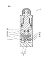
 restoration assisting member 5 assists the restoration of the tube 3, not only can the tube 3 be restored quickly, but the tube 3 is left in a fully closed state for a long period of time. In this case, it is possible to prevent the inner peripheral surface of the tube body 3 from adhering to the pinch valve from being opened, and preventing the pinch valve from being fully opened to ensure a predetermined flow rate. In particular, when a pinch valve is installed in the device, the operation is often stopped for a long time due to factory inspection or production adjustment. Therefore, the inner peripheral surface of the tube 3 is prevented from sticking and the operation is resumed. It is important that the pinch valve is fully opened later to ensure the flow rate.

―第二の実施の形態―
以下、図6を参照して、本発明によるピンチバルブの第二の実施の形態について説明する。図6は本発明の第二の実施の形態に係るピンチバルブの概略構成を示す流路軸線と直行する方向からの縦断面図である。第二の実施の形態が第一の実施形態と異なる点は、主に、復元補助部材5がピストン12に一体的に固定されていることである。なお、図6では第一の実施の形態と同様の作用や機能を有する構成要素には図1〜5と同一の符号を付し、以下では第一の実施の形態との相違点を主に説明する。
-Second embodiment-
Hereinafter, a second embodiment of the pinch valve according to the present invention will be described with reference to FIG. FIG. 6 is a longitudinal sectional view from the direction orthogonal to the flow path axis showing the schematic configuration of the pinch valve according to the second embodiment of the present invention. The second embodiment differs from the first embodiment mainly in that the restoration assisting member 5 is integrally fixed to the piston 12. In FIG. 6, components having the same operations and functions as those in the first embodiment are denoted by the same reference numerals as in FIGS. 1 to 5, and the differences from the first embodiment are mainly described below. explain.

第二の実施の形態では、シリンダー本体8はPPS製である。図6に示すように、シリンダー本体8の中間部には、ピストン12の円盤部24と復元補助部材5の固定部31とを連結する一対の連結軸部51が貫通する貫通孔52が形成されている。   In the second embodiment, the cylinder body 8 is made of PPS. As shown in FIG. 6, a through hole 52 through which a pair of connecting shaft portions 51 that connect the disk portion 24 of the piston 12 and the fixing portion 31 of the restoration assisting member 5 pass is formed in the intermediate portion of the cylinder body 8. ing.

第二の実施の形態では、ピストン12はSUS製である。図6に示すように、円盤部24の下面には一対の連結軸部51が突出して溶接固定されている。連結軸部51は円柱形状であり、外周面にはOリングが装着されている。連結軸部51の先端部には流路軸線と直行する方向に貫通孔53が形成されている。連結軸部51はピストン12の貫通孔52に上下動可能かつ水密状態で挿入される。   In the second embodiment, the piston 12 is made of SUS. As shown in FIG. 6, a pair of connecting shaft portions 51 protrude and are fixed to the lower surface of the disk portion 24 by welding. The connecting shaft portion 51 has a cylindrical shape, and an O-ring is mounted on the outer peripheral surface. A through hole 53 is formed at the distal end portion of the connecting shaft portion 51 in a direction perpendicular to the flow path axis. The connecting shaft portion 51 is inserted into the through hole 52 of the piston 12 so as to be vertically movable and in a watertight state.

第二の実施の形態では、一対の復元補助部材5はPPS製である。図6に示すように、固定部31は復元補助部材5とピストン12とを固定する部分であり、固定部31の上面には、連結軸部51が連結される断面矩形状の連結孔54が形成されている。連結軸部51の先端部を連結孔54に嵌挿し、固定部31の貫通孔38と連結軸部51の貫通孔53に固定ピン55を嵌挿することによって、ピストン12と復元補助部材5とが一体的に固定される。   In the second embodiment, the pair of restoration assisting members 5 are made of PPS. As shown in FIG. 6, the fixing portion 31 is a portion for fixing the restoration assisting member 5 and the piston 12, and a connecting hole 54 having a rectangular cross section to which the connecting shaft portion 51 is connected is formed on the upper surface of the fixing portion 31. Is formed. By inserting the distal end portion of the connecting shaft portion 51 into the connecting hole 54 and inserting the fixing pin 55 into the through hole 38 of the fixing portion 31 and the through hole 53 of the connecting shaft portion 51, the piston 12, the restoration assisting member 5, Are fixed together.

第二の実施の形態において、ピンチバルブの他の構成は第一の実施の形態と同様なので説明を省略する。第二の実施の形態の復元補助部材5が管体3の復元を補助する作用は第一の実施の形態と同様なので説明を省略する。   In the second embodiment, since the other configuration of the pinch valve is the same as that of the first embodiment, the description thereof is omitted. Since the operation of assisting the restoration of the
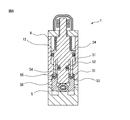
 tubular body 3 by the restoration assisting member 5 of the second embodiment is the same as that of the first embodiment, the description thereof is omitted.

―第三の実施の形態―
以下、図7を参照して、本発明によるピンチバルブの第三の実施の形態について説明する。図7は本発明の第三の実施の形態に係るピンチバルブの概略構成を示す縦断面図である。第三の実施の形態が第一の実施形態と異なる点は、主に、挟圧子4が流路2を全開状態および全閉状態の二段階の状態にするように駆動されるとともに、挟圧子4の上流側に、管体3を押圧して流路2を任意の開度状態に調整する調整用の挟圧子66が配置されていることである。なお、図7では第一の実施の形態と同様の作用や機能を有する構成要素には図1〜5と同一の符号を付し、以下では第一の実施の形態との相違点を主に説明する。
-Third embodiment-
Hereinafter, a third embodiment of the pinch valve according to the present invention will be described with reference to FIG. FIG. 7 is a longitudinal sectional view showing a schematic configuration of a pinch valve according to a third embodiment of the present invention. The third embodiment is different from the first embodiment mainly in that the sandwiching element 4 is driven so that the flow path 2 is in a two-stage state of a fully open state and a fully closed state, and the sandwiching element. 4, an adjustment pinching element 66 that presses the tube body 3 and adjusts the flow path 2 to an arbitrary opening state is disposed on the upstream side. In FIG. 7, components having the same operations and functions as those in the first embodiment are denoted by the same reference numerals as in FIGS. 1 to 5, and the differences from the first embodiment are mainly described below. explain.

第三の実施の形態に係るピンチバルブは、流路2を任意の開度状態に調整する流量調整用のピンチバルブと流路2を全開状態および全閉状態の二段階の状態にする開閉操作用のピンチバルブとを直列に接続している。また、流量調整用のピンチバルブは上流側に配置され、開閉操作用のピンチバルブは下流側に配置される。また、流量調整用のピンチバルブと開閉操作用のピンチバルブは共通の本体61、シリンダー本体63、管体3、継手11を有している。開閉操作用のピンチバルブは第一の実施の形態と同様な構成である。流量調整用のピンチバルブは、本体61、管体3、継手11、挟圧子66、駆動部77を備える。また、流量調整用ピンチバルブの駆動部77はシリンダー本体63、ステム69、ナット72、操作部材76を備える。   The pinch valve according to the third embodiment has a flow adjustment pinch valve that adjusts the flow path 2 to an arbitrary opening state and an opening / closing operation that sets the flow path 2 in a two-stage state of a fully open state and a fully closed state. A pinch valve is connected in series. The pinch valve for adjusting the flow rate is arranged on the upstream side, and the pinch valve for opening / closing operation is arranged on the downstream side. Further, the pinch valve for flow rate adjustment and the pinch valve for opening / closing operation have a common main body 61, cylinder main body 63, pipe body 3, and joint 11. The pinch valve for opening / closing operation has the same configuration as that of the first embodiment. The pinch valve for adjusting the flow rate includes a main body 61, a pipe body 3, a joint 11, a pinching element 66, and a drive unit 77. The drive unit 77 of the flow rate adjusting pinch valve includes a cylinder body 63, a stem 69, a nut 72, and an operation member 76.

第三の実施の形態において、本体61はPPS製である。図7に示すように、管体3を収容する管体収容部13の上流側の底面には、流路軸線と直行する方向に断面半円形状の突条62が形成されている。   In the third embodiment, the main body 61 is made of PPS. As shown in FIG. 7, a protrusion 62 having a semicircular cross section is formed on the bottom surface on the upstream side of the tube housing portion 13 that houses the tube 3 in a direction perpendicular to the flow path axis.

第三の実施の形態において、シリンダー本体63はPPS製である。図7に示すように、シリンダー本体63の上流側の上部には、上流側に向かって管体3方向に傾く座部64が形成されている。座部64の上端面には、座部64の上面と垂直に形成されシリンダー本体63の下面に貫通する貫通孔65が形成されている。すなわち、貫通孔65は流路軸線に対して斜めに形成されている。貫通孔65の上部には雌ネジ部が形成されている。シリンダー本体63の上流側の下部には、断面矩形状の空間であり挟圧子66を収容する第三収容部67が形成されている。第三収容部67の壁面には、挟圧子66の動作を上下動のみに規制するガイド68が形成されている。また、貫通孔65は第二収容部17と第三収容部67と連通している。   In the third embodiment, the cylinder body 63 is made of PPS. As shown in FIG. 7, a seat portion 64 that is inclined in the direction of the tubular body 3 toward the upstream side is formed on the upstream side of the cylinder body 63. A through hole 65 that is formed perpendicular to the upper surface of the seat portion 64 and penetrates the lower surface of the cylinder body 63 is formed in the upper end surface of the seat portion 64. That is, the through hole 65 is formed obliquely with respect to the flow path axis. A female screw portion is formed in the upper portion of the through hole 65. In the lower part on the upstream side of the cylinder body 63, a third accommodating portion 67 that is a space having a rectangular cross section and accommodates the pinching element 66 is formed. A guide 68 is formed on the wall surface of the third housing portion 67 to restrict the operation of the pinching element 66 to only vertical movement. In addition, the through hole 65 communicates with the second housing portion 17 and the third housing portion 67.

第三の実施の形態において、ステム69はSUS製である。図7に示すように、ステム69は第一ステム70と第二ステム71から構成され、差動ネジの機構を有している。第一ステム70は円筒形状であり、外部には貫通孔65の雌ネジ部および第一ステム70の位置を固定するナット72と螺合される雄ネジ部が形成され、内部には第二ステム71の雄ネジ部と螺合される雌ネジ部が形成されている。第一ステム70の管体3側の先端部には貫通孔65と略同径の鍔部が形成され、他方の先端部には操作部材76が装着されている。第二ステム71は円柱形状であり、外部には第一ステム70の内部に形成されている雌ネジ部と螺合される雄ネジ部が形成されている。第二ステム71の管体3側の先端部には断面が管体3側に向かって扇形状である押出部73が形成されている。押出部73の下面には、流路軸線方向に溝(図示せず)が形成され、その溝は挟圧子66の上面に形成された突条74に遊嵌されている。   In the third embodiment, the stem 69 is made of SUS. As shown in FIG. 7, the stem 69 includes a first stem 70 and a second stem 71, and has a differential screw mechanism. The first stem 70 has a cylindrical shape, and has a female screw portion of the through-hole 65 and a male screw portion screwed with a nut 72 for fixing the position of the first stem 70 formed outside, and a second stem inside. A female screw portion to be screwed with the male screw portion 71 is formed. A flange portion having the same diameter as the through hole 65 is formed at the distal end portion of the first stem 70 on the tube body 3 side, and an operation member 76 is attached to the other distal end portion. The second stem 71 has a cylindrical shape, and a male screw portion that is screwed with a female screw portion formed inside the first stem 70 is formed on the outside. An extruding portion 73 having a fan-shaped cross section toward the tube body 3 side is formed at the distal end portion of the second stem 71 on the tube body 3 side. A groove (not shown) is formed in the flow path axis direction on the lower surface of the pushing portion 73, and the groove is loosely fitted to a protrusion 74 formed on the upper surface of the pinching element 66.

第三の実施の形態において、挟圧子66はPPS製である。図7に示すように、挟圧子66は断面矩形状に形成され、下面には流路軸線と直行する方向に突出する、断面かまぼこ形状の突条75が形成されている。突条75は突条62と対向して形成されている。挟圧子66には第三収容部67に設けられた、ここでは係止溝であるガイド68に対応するガイド受け(図示せず)が形成されている。挟圧子66に形成されたガイド受けにガイド68が遊嵌されることによって挟圧子66の動作は上下動のみに規制される。挟圧子66の上面には流路軸線方向に平行に延びる突条(図示せず)が形成されており、第二ステム71の下に位置する押出部73の下面に形成されている溝(図示せず)と上記突条が遊嵌状態で接続されることによって、挟圧子66は第二ステム71の斜め方向の進退をうけて上下動することができる。第三の実施の形態において、ピンチバルブの他の構成は第一の実施の形態と同様なので説明を省略する。   In the third embodiment, the pincer 66 is made of PPS. As shown in FIG. 7, the pinching element 66 is formed in a rectangular shape in cross section, and a protrusion 75 having a semi-cylindrical cross section that protrudes in a direction perpendicular to the flow path axis is formed on the lower surface. The ridge 75 is formed to face the ridge 62. The pinching element 66 is formed with a guide receiver (not shown) corresponding to a guide 68 which is a locking groove provided in the third housing 67. When the guide 68 is loosely fitted to the guide receiver formed on the pinching element 66, the operation of the pinching element 66 is restricted only to the vertical movement. A protrusion (not shown) extending in parallel with the flow path axis direction is formed on the upper surface of the sandwiching element 66, and a groove (see FIG. 5) formed on the lower surface of the pushing portion 73 positioned below the second stem 71. (Not shown) and the protrusions are connected in a loose-fitting state, whereby the pinching element 66 can move up and down as the second stem 71 advances and retracts in the oblique direction. In the third embodiment, since the other configuration of the pinch valve is the same as that of the first embodiment, the description thereof is omitted.

第三の実施の形態では、挟圧子4が流路2を全開状態および全閉状態の二段階の状態にするように駆動され、挟圧子66が流路2を任意の開度状態に調整するように駆動される。挟圧子4が流路2を全開状態および全閉状態の二段階の状態にする作用は第一の実施の形態と同様なので説明を省略する。図7に示すように、ピンチバルブが全開状態において、操作部材76を回転させると第一ステム70の軸方向に移動しながら第一ステム70が回転する。第一ステム70と第二ステム71は差動ネジの機構を有しており、第二ステム71は挟圧子66との上記接続によって進退可能かつ回動不能に配置されていることから、第一ステム70が回転することによって、第二ステム71が第二ステム71の軸方向に移動する。第二ステム71が管体3に向かって移動すると、挟圧子66は押出部73に押され管体3に向かって移動し、管体3を押圧する。さらに操作部材76を操作すると挟圧子66によって管体3はさらに押し潰され、流路2が所望の開度状態に調整される。   In the third embodiment, the sandwiching element 4 is driven to bring the flow path 2 into a two-stage state of a fully open state and a fully closed state, and the sandwiching element 66 adjusts the flow path 2 to an arbitrary opening state. To be driven. Since the operation of the pinch element 4 to bring the flow path 2 into a two-stage state of the fully open state and the fully closed state is the same as that of the first embodiment, the description thereof is omitted. As shown in FIG. 7, when the operation member 76 is rotated with the pinch valve fully opened, the first stem 70 rotates while moving in the axial direction of the first stem 70. The first stem 70 and the second stem 71 have a differential screw mechanism, and the second stem 71 is disposed so as to be movable forward and backward and non-rotatable by the above connection with the pinching element 66. As the stem 70 rotates, the second stem 71 moves in the axial direction of the second stem 71. When the second stem 71 moves toward the tube body 3, the pinching element 66 is pushed by the pushing portion 73 and moves toward the tube body 3 to press the tube body 3. When the operation member 76 is further operated, the tubular body 3 is further crushed by the pinching element 66, and the flow path 2 is adjusted to a desired opening state.

流路2が挟圧子66によって所望の開度状態に調整された状態から、流路2が全閉状態になるように挟圧子4が駆動されると、ピンチバルブ1は全閉状態となる。そして、ふたたび流路2が全開状態になるように挟圧子4が駆動されると、ピンチバルブは所望の開度状態に調整された状態となる。このように、流量調整用のピンチバルブと開閉操作用のピンチバルブとを直列に配置することによって、全閉状態から流量調整状態に速やかに切り換えることができる。このとき、上流側に流量調整用のピンチバルブを配置し、下流側に開閉操作用のピンチバルブを配置することによって、全閉状態から流量調整状態にしたときに短時間で流量を安定させることができる。   When the pincer 4 is driven so that the flow path 2 is fully closed from the state where the flow path 2 is adjusted to a desired opening state by the pinch 66, the pinch valve 1 is fully closed. When the pincer 4 is driven so that the flow path 2 is fully opened again, the pinch valve is adjusted to a desired opening state. Thus, by arranging the pinch valve for adjusting the flow rate and the pinch valve for opening / closing operation in series, it is possible to quickly switch from the fully closed state to the flow rate adjusted state. At this time, by arranging a pinch valve for flow rate adjustment on the upstream side and a pinch valve for opening / closing operation on the downstream side, the flow rate can be stabilized in a short time when the flow rate is adjusted from the fully closed state. Can do.

次に、流路2が所望の開度状態に調整された状態から、操作部材76を反対方向に回転させると第一ステム70が反対方向に回転し、第二ステム71が管体3から遠ざかる方向に移動する。このとき、押出部73も管体3から遠ざかる方向に移動するので、挟圧子66は管体3の復元力を受けて鉛直方向に移動する。挟圧子66による押圧力が取り除かれた管体3は自己の復元力によって全開状態に向かって復元する。このとき、挟圧子66の移動を容易にするとともに、ステム69のバックラッシによる開度の誤差を抑えるために、挟圧子66の下側に付勢体を配置してもよい。   Next, when the operation member 76 is rotated in the opposite direction from the state in which the flow path 2 is adjusted to a desired opening state, the first stem 70 rotates in the opposite direction, and the second stem 71 moves away from the tube body 3. Move in the direction. At this time, the pushing portion 73 also moves in a direction away from the tube 3, so that the pinching element 66 moves in the vertical direction by receiving the restoring force of the tube 3. The tube body 3 from which the pressing force by the pinching element 66 has been removed is restored toward the fully opened state by its own restoring force. At this time, in order to facilitate the movement of the pincer 66 and to suppress an error in opening due to backlash of the stem 69, an urging body may be disposed below the pincer 66.

また、ピンチバルブは管体3を押圧することで流路2を開閉することができるので、ひとつの本体7にふたつの挟圧子4、66を容易に配置することができるとともに、挟圧子4と挟圧子66の間隔を狭くすることができる。また、挟圧子4、66間の間隔を狭くすることができるので、ひとつの本体61にふたつの挟圧子4、66を配置してもピンチバルブの面間寸法を小さくすることができる。さらに、挟圧子66を駆動するステム69が挟圧子4を駆動するピストン12に対して斜めに配置されることによって、ステム69とピストン12の間隔を狭くすることができるので、ピンチバルブ1の面間寸法をさらに小さくすることができる。   In addition, since the pinch valve can open and close the flow path 2 by pressing the tube body 3, the two pinching elements 4 and 66 can be easily arranged in one main body 7. The interval between the pinching elements 66 can be reduced. Moreover, since the space | interval between the pinching elements 4 and 66 can be narrowed, even if it arrange | positions the two pinching elements 4 and 66 in the one main body 61, the surface-to-surface dimension of a pinch valve can be made small. Further, the distance between the stem 69 and the piston 12 can be narrowed by arranging the stem 69 for driving the pinching element 66 obliquely with respect to the piston 12 for driving the pinching element 4. The interstitial dimension can be further reduced.

第三の実施の形態では、挟圧子66と挟圧子4がともに管体3の上側に配置されているが、挟圧子66が管体3の下側に配置されてもよい。すなわち、流量調整用のピンチバルブと開閉操作用のピンチバルブが管体3を挟んで配置されてもよい。このように配置すると、流量調整用のピンチバルブの駆動部77と開閉操作用のピンチバルブの駆動部6が干渉しないので、ピンチバルブの面間寸法を小さくすることができる。   In the third embodiment, the sandwiching element 66 and the sandwiching element 4 are both disposed on the upper side of the tube body 3, but the sandwiching element 66 may be disposed on the lower side of the tube body 3. That is, a pinch valve for adjusting the flow rate and a pinch valve for opening / closing operation may be arranged with the tube body 3 interposed therebetween. When arranged in this way, the pinch valve drive unit 77 for flow rate adjustment and the pinch valve drive unit 6 for opening / closing operation do not interfere with each other, so that the dimension between the surfaces of the pinch valve can be reduced.

なお、上記の第一の実施の形態〜第三の実施の形態におけるピンチバルブの本体7、61、シリンダー本体8、63、継手11、ピストン12、ステム69、挟圧子4、66、復元補助部材5などの各種構成部品は、各種構成部品に求められる剛性を満たす材料であれば、金属、プラスチック、ガラス、陶器など特に限定されるものではないが、PPS、ポリ塩化ビニル、ポリプロピレン、ポリエチレン、ポリビニリデンフルオロライド、ポリテトラフルオロエチレン、SUSなどが好ましい。また、上記の第一の実施の形態〜第三の実施の形態では、ピンチバルブの挟圧子4、66がそれぞれ空動式、手動式の駆動部6、77で昇降されているが、挟圧子4、66が電気駆動で昇降されてもよく、挟圧子4、66の駆動方式は特に限定されない。   The pinch valve bodies 7 and 61, the cylinder bodies 8 and 63, the joint 11, the piston 12, the stem 69, the sandwiching elements 4 and 66, and the restoration assisting member in the first to third embodiments described above. Various components such as 5 are not particularly limited as long as the material satisfies the rigidity required for various components, such as metal, plastic, glass, ceramics, but PPS, polyvinyl chloride, polypropylene, polyethylene, poly Vinylidene fluoride, polytetrafluoroethylene, SUS and the like are preferable. Further, in the first to third embodiments, the pinch valve pinching elements 4 and 66 are lifted and lowered by the pneumatic and manual drive units 6 and 77, respectively. 4 and 66 may be moved up and down by electric drive, and the driving method of the sandwiching elements 4 and 66 is not particularly limited.

なお、上記の第一の実施の形態〜第三の実施の形態を任意に組み合わせてピンチバルブを構成してもよい。すなわち、本発明の特徴および機能を実現できる限り、本発明は実施の形態のピンチバルブに限定されない。   In addition, you may comprise a pinch valve | bulb combining said 1st embodiment-3rd embodiment arbitrarily. That is, the present invention is not limited to the pinch valve of the embodiment as long as the features and functions of the present invention can be realized.

1 ピンチバルブ
2 流路
3 管体
4 挟圧子
5 復元補助部材
6 駆動部
7 本体
8 シリンダー本体
12 ピストン
13 管体収容部
14 復元補助部材収容部
24 円盤部
25 開度制御部
26 軸部
31 固定部
32 管体受容部
33 補助部
34 曲面
35 平面
36 テーパー面
37 固定ピン
51 連通軸部
55 固定ピン
61 本体
63 シリンダー本体
66 挟圧子
69 ステム
73 押出部
76 操作部材
77 駆動部
DESCRIPTION OF SYMBOLS 1 Pinch valve 2 Flow path 3 Tubing body 4 Pinching element 5 Restoration auxiliary member 6 Drive part 7 Main body 8 Cylinder body 12 Piston 13 Pipe body accommodating part 14 Restoring auxiliary member accommodating part 24 Disc part 25 Opening control part 26 Shaft part 31 Fixed Portion 32 Tubular receiving portion 33 Auxiliary portion 34 Curved surface 35 Plane 36 Tapered surface 37 Fixed pin 51 Communication shaft portion 55 Fixed pin 61 Main body 63 Cylinder main body 66 Pinching member 69 Stem 73 Extruding portion 76 Operating member 77 Driving portion

Claims (6)

本体と、
弾性を有し内部に流路を有するとともに前記本体に収容される管体と、
前記管体を押圧しまたは押圧を解除して流路を閉状態または開状態にする押圧手段と、
前記管体が押圧された状態から開状態に復元する動作を補助する復元補助手段と、
を備えるピンチバルブにおいて、
前記復元補助手段は、
前記押圧手段が前記管体を押圧したときに、押圧され変形した前記管体の少なくとも一部を受容する凹面を有する管体受容部と、
前記管体の復元を補助するように構成された補助部であって、前記凹面から連続的に隆起するとともに、前記押圧手段が前記管体の押圧を解除したときに前記押圧手段の押圧方向及び流路軸線方向と直交する方向に前記管体を押圧する、凸面を有する補助部と、
前記押圧手段に一体的に固定される固定部と、
を有し、
前記復元補助手段が前記押圧手段と同一行程で移動し、
前記補助部の前記流路軸線方向の長さが全閉状態の前記管体の内周面が接触している部分の流路軸線方向の長さよりも長いことを特徴とするピンチバルブ。
The body,
A tube body having elasticity and having a flow path therein and housed in the main body;
A pressing means for pressing the tube or releasing the pressing to close or open the flow path;
Restoration assisting means for assisting the operation of restoring the tube body from the pressed state to the open state;
In a pinch valve comprising:
The restoration assisting means includes
A tubular body receiving portion having a concave surface for receiving at least a part of the tubular body that is pressed and deformed when the pressing means presses the tubular body;
An auxiliary portion configured to assist in the restoration of the tubular body, and is continuously raised from the concave surface, and when the pressing means releases the pressing of the tubular body, the pressing direction of the pressing means and An auxiliary portion having a convex surface that presses the tubular body in a direction orthogonal to the flow path axial direction ;
A fixing portion integrally fixed to the pressing means;
Have
The restoration assisting means moves in the same process as the pressing means ,
A pinch valve characterized in that the length of the auxiliary portion in the flow path axis direction is longer than the length in the flow path axis direction of the portion where the inner peripheral surface of the tubular body in the fully closed state is in contact .
前記本体は、
前記管体を収容する管体収容部と、
前記管体収容部に連通するとともに全閉状態において前記復元補助手段を収容する復元補助手段収容部と、
を備え、
前記復元補助手段収容部の深さが前記管体収容部の深さより深いことを特徴とする、
請求項1に記載のピンチバルブ。
The body is
A tube housing portion for housing the tube;
A restoration assisting means accommodating part that communicates with the tube accommodating part and accommodates the restoration assisting means in a fully closed state;
With
The depth of the restoration assisting means accommodating portion is deeper than the depth of the tube accommodating portion,
The pinch valve according to claim 1.
前記復元補助手段が前記管体の両側に対向して配置され、
前記管体が全開状態に近づくにつれて、前記補助部の前記管体に接触している部分同士の間隔が狭くなるように、前記補助部の前記管体側の凸面が傾斜面または曲面を含むことを特徴とする、
請求項に記載のピンチバルブ。
The restoration assisting means is disposed opposite to both sides of the tubular body;
The convex surface on the tubular body side of the auxiliary portion includes an inclined surface or a curved surface so that an interval between portions of the auxiliary portion that are in contact with the tubular body becomes narrower as the tubular body approaches a fully opened state. Features
The pinch valve according to claim 2 .
前記復元補助手段が前記管体の両側に対向して配置され、
全開状態における前記補助部の前記管体に接触している部分同士の間隔が、前記管体の外径よりも僅かに狭いことを特徴とする、
請求項2又は3に記載のピンチバルブ。
The restoration assisting means is disposed opposite to both sides of the tubular body;
The interval between the portions of the auxiliary portion in contact with the tubular body in the fully open state is slightly narrower than the outer diameter of the tubular body,
The pinch valve according to claim 2 or 3 .
前記補助部の少なくとも前記管体に接触する面の静摩擦係数μが、
0.01≦μ≦0.6
であることを特徴とする、
請求項2乃至請求項のいずれか1項に記載のピンチバルブ。
The coefficient of static friction μ of the surface of the auxiliary portion that contacts at least the tubular body is
0.01 ≦ μ ≦ 0.6
It is characterized by
The pinch valve according to any one of claims 2 to 4 .
前記押圧手段が前記流路を全開状態および全閉状態の二段階の状態にするように駆動され、
前記押圧手段より前記管体の流路の上流側若しくは前記管体の下側又は前記管体を挟んだ反対側に、前記管体を押圧して前記流路の開度を任意に調整する調整用押圧手段が装着されていることを特徴とする、
請求項1乃至請求項のいずれか1項に記載のピンチバルブ。
The pressing means is driven to bring the flow path into a two-stage state of a fully open state and a fully closed state,
Adjustment for arbitrarily adjusting the opening degree of the flow path by pressing the tubular body on the upstream side of the flow path of the tubular body from the pressing means, on the lower side of the tubular body, or on the opposite side of the tubular body. It is characterized by being equipped with a pressing means for,
The pinch valve according to any one of claims 1 to 5 .
JP2014045566A 2014-03-07 2014-03-07 Pinch valve Active JP6355366B2 (en)

Priority Applications (1)

Application Number Priority Date Filing Date Title
JP2014045566A JP6355366B2 (en) 2014-03-07 2014-03-07 Pinch valve

Applications Claiming Priority (1)

Application Number Priority Date Filing Date Title
JP2014045566A JP6355366B2 (en) 2014-03-07 2014-03-07 Pinch valve

Publications (3)

Publication Number Publication Date
JP2015169292A JP2015169292A (en) 2015-09-28
JP2015169292A5 JP2015169292A5 (en) 2017-03-09
JP6355366B2 true JP6355366B2 (en) 2018-07-11

Family

ID=54202212

Family Applications (1)

Application Number Title Priority Date Filing Date
JP2014045566A Active JP6355366B2 (en) 2014-03-07 2014-03-07 Pinch valve

Country Status (1)

Country Link
JP (1) JP6355366B2 (en)

Families Citing this family (4)

* Cited by examiner, † Cited by third party
Publication number Priority date Publication date Assignee Title
JP6717036B2 (en) * 2016-04-28 2020-07-01 株式会社ジェイ・エム・エス Peritoneal dialysis machine
JP7096844B2 (en) * 2017-05-15 2022-07-06 カーテン コントロールズ リミテッド Pinch valve
JP2022126490A (en) * 2021-02-18 2022-08-30 Ckd株式会社 pinch valve
CN113585400A (en) * 2021-09-01 2021-11-02 杭州那复环保科技有限公司 Water purifier under kitchen that portable water receiving uses control mechanism for purifier under kitchen

Family Cites Families (6)

* Cited by examiner, † Cited by third party
Publication number Priority date Publication date Assignee Title
JPS46631Y1 (en) * 1966-07-27 1971-01-11
JPS5240828A (en) * 1975-09-26 1977-03-30 Toyota Motor Co Ltd Pinch valve device
JPS5682322A (en) * 1979-12-10 1981-07-06 Tokai:Kk Valve device for gas lighter
JPS6377173U (en) * 1986-11-07 1988-05-23
JPH0265771U (en) * 1988-11-09 1990-05-17
JP2841878B2 (en) * 1991-01-23 1998-12-24 凸版印刷株式会社 Tube opening and closing jig

Also Published As

Publication number Publication date
JP2015169292A (en) 2015-09-28

Similar Documents

Publication Publication Date Title
JP6355366B2 (en) Pinch valve
KR101013441B1 (en) Pinch valve
EP1253360B1 (en) Pinch valve
EP2777759B1 (en) Needleless connector with flexible valve
EP2619494B1 (en) Bonnet apparatus to provide live-loading to a seal
JP5764579B2 (en) Vacuum valve
JP5017374B2 (en) Pressure regulating valve
KR20070032821A (en) Ball valve seat structure
JP2002161988A (en) Pinch valve
JP4994082B2 (en) Piping material
JP2012524558A (en) Valve device, valve insert, external functional means, processing equipment, and method
CN110234914B (en) Composite sealing element
TWI647394B (en) Manual valve
JP4340119B2 (en) Chemical valve
CN205504121U (en) Clamp type valve gap subassembly and have axial -flow type control valve of this subassembly
JP4667964B2 (en) Flow control valve
JP6261593B2 (en) Automatic diaphragm valve for high pressure
JP5571261B1 (en) Pinch valve
JP7328775B2 (en) diaphragm valve
JP2015169292A5 (en)
JP3829109B2 (en) Valve device
WO2017141780A1 (en) Diaphragm valve
JP2023083160A (en) diaphragm valve
US9816620B2 (en) Butterfly valve seal retaining arrangement
JP4230501B2 (en) Valve device

Legal Events

Date Code Title Description
A521 Request for written amendment filed

Free format text: JAPANESE INTERMEDIATE CODE: A523

Effective date: 20170206

A621 Written request for application examination

Free format text: JAPANESE INTERMEDIATE CODE: A621

Effective date: 20170206

A131 Notification of reasons for refusal

Free format text: JAPANESE INTERMEDIATE CODE: A131

Effective date: 20171107

A521 Request for written amendment filed

Free format text: JAPANESE INTERMEDIATE CODE: A523

Effective date: 20171215

TRDD Decision of grant or rejection written
A01 Written decision to grant a patent or to grant a registration (utility model)

Free format text: JAPANESE INTERMEDIATE CODE: A01

Effective date: 20180515

A61 First payment of annual fees (during grant procedure)

Free format text: JAPANESE INTERMEDIATE CODE: A61

Effective date: 20180612

R150 Certificate of patent or registration of utility model

Ref document number: 6355366

Country of ref document: JP

Free format text: JAPANESE INTERMEDIATE CODE: R150

R250 Receipt of annual fees

Free format text: JAPANESE INTERMEDIATE CODE: R250

R250 Receipt of annual fees

Free format text: JAPANESE INTERMEDIATE CODE: R250

R250 Receipt of annual fees

Free format text: JAPANESE INTERMEDIATE CODE: R250