JP6353145B2 - Tissue oxygenation measurement system and method - Google Patents
Tissue oxygenation measurement system and method Download PDFInfo
- Publication number
- JP6353145B2 JP6353145B2 JP2017176628A JP2017176628A JP6353145B2 JP 6353145 B2 JP6353145 B2 JP 6353145B2 JP 2017176628 A JP2017176628 A JP 2017176628A JP 2017176628 A JP2017176628 A JP 2017176628A JP 6353145 B2 JP6353145 B2 JP 6353145B2
- Authority
- JP
- Japan
- Prior art keywords
- spectral
- wavelengths
- images
- spectral bands
- light
- Prior art date
- Legal status (The legal status is an assumption and is not a legal conclusion. Google has not performed a legal analysis and makes no representation as to the accuracy of the status listed.)
- Active
Links
- 238000005259 measurement Methods 0.000 title claims description 26
- 230000000287 tissue oxygenation Effects 0.000 title claims description 22
- 238000000034 method Methods 0.000 title description 64
- 230000003595 spectral effect Effects 0.000 claims description 292
- 238000003384 imaging method Methods 0.000 claims description 151
- 230000003287 optical effect Effects 0.000 claims description 142
- XUMBMVFBXHLACL-UHFFFAOYSA-N Melanin Chemical compound O=C1C(=O)C(C2=CNC3=C(C(C(=O)C4=C32)=O)C)=C2C4=CNC2=C1C XUMBMVFBXHLACL-UHFFFAOYSA-N 0.000 claims description 64
- 238000004891 communication Methods 0.000 claims description 47
- INGWEZCOABYORO-UHFFFAOYSA-N 2-(furan-2-yl)-7-methyl-1h-1,8-naphthyridin-4-one Chemical compound N=1C2=NC(C)=CC=C2C(O)=CC=1C1=CC=CO1 INGWEZCOABYORO-UHFFFAOYSA-N 0.000 claims description 38
- 108010002255 deoxyhemoglobin Proteins 0.000 claims description 38
- 108010064719 Oxyhemoglobins Proteins 0.000 claims description 36
- 238000010521 absorption reaction Methods 0.000 claims description 36
- 238000010183 spectrum analysis Methods 0.000 claims description 32
- MYMOFIZGZYHOMD-UHFFFAOYSA-N Dioxygen Chemical class O=O MYMOFIZGZYHOMD-UHFFFAOYSA-N 0.000 description 128
- 210000001519 tissue Anatomy 0.000 description 83
- 208000025865 Ulcer Diseases 0.000 description 40
- 238000000701 chemical imaging Methods 0.000 description 40
- 238000012545 processing Methods 0.000 description 38
- 230000009102 absorption Effects 0.000 description 30
- 210000003491 skin Anatomy 0.000 description 24
- 238000012937 correction Methods 0.000 description 23
- 238000001228 spectrum Methods 0.000 description 23
- 231100000397 ulcer Toxicity 0.000 description 23
- 238000009792 diffusion process Methods 0.000 description 20
- 238000005286 illumination Methods 0.000 description 20
- 208000008960 Diabetic foot Diseases 0.000 description 17
- 208000004210 Pressure Ulcer Diseases 0.000 description 17
- 238000004458 analytical method Methods 0.000 description 17
- 230000036269 ulceration Effects 0.000 description 17
- 206010011985 Decubitus ulcer Diseases 0.000 description 15
- 206010012601 diabetes mellitus Diseases 0.000 description 15
- 206010019280 Heart failures Diseases 0.000 description 14
- 238000004451 qualitative analysis Methods 0.000 description 14
- 230000035945 sensitivity Effects 0.000 description 14
- 208000005764 Peripheral Arterial Disease Diseases 0.000 description 13
- 208000030831 Peripheral arterial occlusive disease Diseases 0.000 description 13
- QVGXLLKOCUKJST-UHFFFAOYSA-N atomic oxygen Chemical compound [O] QVGXLLKOCUKJST-UHFFFAOYSA-N 0.000 description 12
- 210000004207 dermis Anatomy 0.000 description 12
- 229910052760 oxygen Inorganic materials 0.000 description 12
- 239000001301 oxygen Substances 0.000 description 12
- 206010028980 Neoplasm Diseases 0.000 description 11
- 239000008280 blood Substances 0.000 description 11
- 210000004369 blood Anatomy 0.000 description 11
- 238000001514 detection method Methods 0.000 description 11
- 208000037265 diseases, disorders, signs and symptoms Diseases 0.000 description 11
- 230000001427 coherent effect Effects 0.000 description 10
- 238000010586 diagram Methods 0.000 description 10
- 201000011510 cancer Diseases 0.000 description 9
- 239000000306 component Substances 0.000 description 9
- 238000009826 distribution Methods 0.000 description 9
- 210000002615 epidermis Anatomy 0.000 description 9
- 208000028867 ischemia Diseases 0.000 description 9
- 235000019557 luminance Nutrition 0.000 description 9
- 239000000126 substance Substances 0.000 description 9
- 238000002835 absorbance Methods 0.000 description 8
- 230000015572 biosynthetic process Effects 0.000 description 8
- 238000003745 diagnosis Methods 0.000 description 8
- 238000011156 evaluation Methods 0.000 description 8
- 210000003414 extremity Anatomy 0.000 description 8
- 208000015181 infectious disease Diseases 0.000 description 8
- 230000000302 ischemic effect Effects 0.000 description 8
- 230000007170 pathology Effects 0.000 description 8
- 238000004088 simulation Methods 0.000 description 8
- 206010007559 Cardiac failure congestive Diseases 0.000 description 7
- 208000005156 Dehydration Diseases 0.000 description 7
- 208000032843 Hemorrhage Diseases 0.000 description 7
- 206010020772 Hypertension Diseases 0.000 description 7
- 206010061218 Inflammation Diseases 0.000 description 7
- 208000004756 Respiratory Insufficiency Diseases 0.000 description 7
- 206010040047 Sepsis Diseases 0.000 description 7
- 208000000558 Varicose Ulcer Diseases 0.000 description 7
- 208000034158 bleeding Diseases 0.000 description 7
- 230000000740 bleeding effect Effects 0.000 description 7
- 238000004422 calculation algorithm Methods 0.000 description 7
- 230000008859 change Effects 0.000 description 7
- 230000018044 dehydration Effects 0.000 description 7
- 238000006297 dehydration reaction Methods 0.000 description 7
- 230000004054 inflammatory process Effects 0.000 description 7
- 201000004193 respiratory failure Diseases 0.000 description 7
- 230000035939 shock Effects 0.000 description 7
- 238000011282 treatment Methods 0.000 description 7
- 206010017711 Gangrene Diseases 0.000 description 6
- 206010020565 Hyperaemia Diseases 0.000 description 6
- 239000000470 constituent Substances 0.000 description 6
- 238000004611 spectroscopical analysis Methods 0.000 description 6
- 230000009724 venous congestion Effects 0.000 description 6
- 108010054147 Hemoglobins Proteins 0.000 description 5
- 102000001554 Hemoglobins Human genes 0.000 description 5
- 238000012512 characterization method Methods 0.000 description 5
- 229940079593 drug Drugs 0.000 description 5
- 239000003814 drug Substances 0.000 description 5
- 230000006870 function Effects 0.000 description 5
- 230000035876 healing Effects 0.000 description 5
- 230000010412 perfusion Effects 0.000 description 5
- 230000008569 process Effects 0.000 description 5
- XLYOFNOQVPJJNP-UHFFFAOYSA-N water Substances O XLYOFNOQVPJJNP-UHFFFAOYSA-N 0.000 description 5
- 102000008186 Collagen Human genes 0.000 description 4
- 108010035532 Collagen Proteins 0.000 description 4
- 210000004027 cell Anatomy 0.000 description 4
- 229920001436 collagen Polymers 0.000 description 4
- 201000010099 disease Diseases 0.000 description 4
- 230000036571 hydration Effects 0.000 description 4
- 238000006703 hydration reaction Methods 0.000 description 4
- 230000003993 interaction Effects 0.000 description 4
- 230000010287 polarization Effects 0.000 description 4
- 238000002310 reflectometry Methods 0.000 description 4
- 238000001356 surgical procedure Methods 0.000 description 4
- 230000004083 survival effect Effects 0.000 description 4
- 230000035899 viability Effects 0.000 description 4
- 239000002131 composite material Substances 0.000 description 3
- 230000000694 effects Effects 0.000 description 3
- 238000005516 engineering process Methods 0.000 description 3
- 238000005534 hematocrit Methods 0.000 description 3
- 230000003902 lesion Effects 0.000 description 3
- 239000000203 mixture Substances 0.000 description 3
- 238000003032 molecular docking Methods 0.000 description 3
- 230000004962 physiological condition Effects 0.000 description 3
- 238000004393 prognosis Methods 0.000 description 3
- 210000005166 vasculature Anatomy 0.000 description 3
- 238000012935 Averaging Methods 0.000 description 2
- BPYKTIZUTYGOLE-IFADSCNNSA-N Bilirubin Chemical compound N1C(=O)C(C)=C(C=C)\C1=C\C1=C(C)C(CCC(O)=O)=C(CC2=C(C(C)=C(\C=C/3C(=C(C=C)C(=O)N\3)C)N2)CCC(O)=O)N1 BPYKTIZUTYGOLE-IFADSCNNSA-N 0.000 description 2
- 208000035346 Margins of Excision Diseases 0.000 description 2
- 238000000862 absorption spectrum Methods 0.000 description 2
- 238000003491 array Methods 0.000 description 2
- 229910002056 binary alloy Inorganic materials 0.000 description 2
- 230000005540 biological transmission Effects 0.000 description 2
- 239000012503 blood component Substances 0.000 description 2
- 230000001413 cellular effect Effects 0.000 description 2
- 238000005094 computer simulation Methods 0.000 description 2
- 230000008878 coupling Effects 0.000 description 2
- 238000010168 coupling process Methods 0.000 description 2
- 238000005859 coupling reaction Methods 0.000 description 2
- 238000002059 diagnostic imaging Methods 0.000 description 2
- 230000009977 dual effect Effects 0.000 description 2
- 230000005670 electromagnetic radiation Effects 0.000 description 2
- 239000000835 fiber Substances 0.000 description 2
- 230000036541 health Effects 0.000 description 2
- 238000002675 image-guided surgery Methods 0.000 description 2
- 230000010354 integration Effects 0.000 description 2
- 230000003211 malignant effect Effects 0.000 description 2
- 235000013372 meat Nutrition 0.000 description 2
- 230000004048 modification Effects 0.000 description 2
- 238000012986 modification Methods 0.000 description 2
- 238000002496 oximetry Methods 0.000 description 2
- 230000035515 penetration Effects 0.000 description 2
- 239000000049 pigment Substances 0.000 description 2
- 238000002271 resection Methods 0.000 description 2
- 239000007787 solid Substances 0.000 description 2
- 238000013179 statistical model Methods 0.000 description 2
- 230000002123 temporal effect Effects 0.000 description 2
- 230000019432 tissue death Effects 0.000 description 2
- 230000000007 visual effect Effects 0.000 description 2
- OZFAFGSSMRRTDW-UHFFFAOYSA-N (2,4-dichlorophenyl) benzenesulfonate Chemical compound ClC1=CC(Cl)=CC=C1OS(=O)(=O)C1=CC=CC=C1 OZFAFGSSMRRTDW-UHFFFAOYSA-N 0.000 description 1
- UHHHTIKWXBRCLT-VDBOFHIQSA-N (4s,4ar,5s,5ar,6r,12ar)-4-(dimethylamino)-1,5,10,11,12a-pentahydroxy-6-methyl-3,12-dioxo-4a,5,5a,6-tetrahydro-4h-tetracene-2-carboxamide;ethanol;hydrate;dihydrochloride Chemical compound O.Cl.Cl.CCO.C1=CC=C2[C@H](C)[C@@H]([C@H](O)[C@@H]3[C@](C(O)=C(C(N)=O)C(=O)[C@H]3N(C)C)(O)C3=O)C3=C(O)C2=C1O.C1=CC=C2[C@H](C)[C@@H]([C@H](O)[C@@H]3[C@](C(O)=C(C(N)=O)C(=O)[C@H]3N(C)C)(O)C3=O)C3=C(O)C2=C1O UHHHTIKWXBRCLT-VDBOFHIQSA-N 0.000 description 1
- 241000502561 Acacia irrorata Species 0.000 description 1
- 201000001320 Atherosclerosis Diseases 0.000 description 1
- 206010010996 Corneal degeneration Diseases 0.000 description 1
- 206010012689 Diabetic retinopathy Diseases 0.000 description 1
- 206010061818 Disease progression Diseases 0.000 description 1
- 208000003790 Foot Ulcer Diseases 0.000 description 1
- 208000032456 Hemorrhagic Shock Diseases 0.000 description 1
- 206010027476 Metastases Diseases 0.000 description 1
- 102100035593 POU domain, class 2, transcription factor 1 Human genes 0.000 description 1
- 101710084414 POU domain, class 2, transcription factor 1 Proteins 0.000 description 1
- 208000018262 Peripheral vascular disease Diseases 0.000 description 1
- 206010049771 Shock haemorrhagic Diseases 0.000 description 1
- 206010040943 Skin Ulcer Diseases 0.000 description 1
- 206010072170 Skin wound Diseases 0.000 description 1
- 230000005856 abnormality Effects 0.000 description 1
- 239000006096 absorbing agent Substances 0.000 description 1
- 230000009471 action Effects 0.000 description 1
- 239000000654 additive Substances 0.000 description 1
- 230000000996 additive effect Effects 0.000 description 1
- 238000002266 amputation Methods 0.000 description 1
- 210000001367 artery Anatomy 0.000 description 1
- 230000002238 attenuated effect Effects 0.000 description 1
- 230000001580 bacterial effect Effects 0.000 description 1
- 230000004888 barrier function Effects 0.000 description 1
- 238000005452 bending Methods 0.000 description 1
- 230000009286 beneficial effect Effects 0.000 description 1
- 230000008901 benefit Effects 0.000 description 1
- 239000003124 biologic agent Substances 0.000 description 1
- 229960000074 biopharmaceutical Drugs 0.000 description 1
- 230000017531 blood circulation Effects 0.000 description 1
- 210000004204 blood vessel Anatomy 0.000 description 1
- 210000000746 body region Anatomy 0.000 description 1
- 210000000988 bone and bone Anatomy 0.000 description 1
- 238000004364 calculation method Methods 0.000 description 1
- 239000003990 capacitor Substances 0.000 description 1
- 239000013043 chemical agent Substances 0.000 description 1
- 238000006243 chemical reaction Methods 0.000 description 1
- 239000007795 chemical reaction product Substances 0.000 description 1
- 230000000295 complement effect Effects 0.000 description 1
- 238000007796 conventional method Methods 0.000 description 1
- 101150047356 dec-1 gene Proteins 0.000 description 1
- 230000001419 dependent effect Effects 0.000 description 1
- 238000013461 design Methods 0.000 description 1
- 238000011161 development Methods 0.000 description 1
- 230000005750 disease progression Effects 0.000 description 1
- 229940069417 doxy Drugs 0.000 description 1
- 238000002474 experimental method Methods 0.000 description 1
- 230000004927 fusion Effects 0.000 description 1
- 230000002068 genetic effect Effects 0.000 description 1
- 229910052736 halogen Inorganic materials 0.000 description 1
- 150000002367 halogens Chemical class 0.000 description 1
- 230000003345 hyperglycaemic effect Effects 0.000 description 1
- 230000028709 inflammatory response Effects 0.000 description 1
- 239000004615 ingredient Substances 0.000 description 1
- 229910052740 iodine Inorganic materials 0.000 description 1
- 239000011630 iodine Substances 0.000 description 1
- 238000002955 isolation Methods 0.000 description 1
- 230000031700 light absorption Effects 0.000 description 1
- 210000003141 lower extremity Anatomy 0.000 description 1
- 208000002780 macular degeneration Diseases 0.000 description 1
- 238000012423 maintenance Methods 0.000 description 1
- 239000000463 material Substances 0.000 description 1
- 238000000691 measurement method Methods 0.000 description 1
- 210000002752 melanocyte Anatomy 0.000 description 1
- 230000009401 metastasis Effects 0.000 description 1
- 238000010295 mobile communication Methods 0.000 description 1
- 230000037311 normal skin Effects 0.000 description 1
- 239000013307 optical fiber Substances 0.000 description 1
- 238000005457 optimization Methods 0.000 description 1
- 230000008520 organization Effects 0.000 description 1
- 238000007500 overflow downdraw method Methods 0.000 description 1
- 230000003647 oxidation Effects 0.000 description 1
- 238000007254 oxidation reaction Methods 0.000 description 1
- 206010033675 panniculitis Diseases 0.000 description 1
- 244000052769 pathogen Species 0.000 description 1
- 238000000513 principal component analysis Methods 0.000 description 1
- 239000000047 product Substances 0.000 description 1
- 238000011321 prophylaxis Methods 0.000 description 1
- 238000009877 rendering Methods 0.000 description 1
- 230000002207 retinal effect Effects 0.000 description 1
- 238000012216 screening Methods 0.000 description 1
- 206010040882 skin lesion Diseases 0.000 description 1
- 231100000444 skin lesion Toxicity 0.000 description 1
- 230000036555 skin type Effects 0.000 description 1
- 210000000434 stratum corneum Anatomy 0.000 description 1
- 210000004003 subcutaneous fat Anatomy 0.000 description 1
- 210000004304 subcutaneous tissue Anatomy 0.000 description 1
- 239000000758 substrate Substances 0.000 description 1
- 230000001225 therapeutic effect Effects 0.000 description 1
- 238000004861 thermometry Methods 0.000 description 1
- 230000001131 transforming effect Effects 0.000 description 1
- 238000002834 transmittance Methods 0.000 description 1
- 238000009827 uniform distribution Methods 0.000 description 1
- 210000001364 upper extremity Anatomy 0.000 description 1
- 210000003462 vein Anatomy 0.000 description 1
- 230000003612 virological effect Effects 0.000 description 1
- 238000001429 visible spectrum Methods 0.000 description 1
- 229910052724 xenon Inorganic materials 0.000 description 1
- FHNFHKCVQCLJFQ-UHFFFAOYSA-N xenon atom Chemical compound [Xe] FHNFHKCVQCLJFQ-UHFFFAOYSA-N 0.000 description 1
Images


Classifications
-
- A—HUMAN NECESSITIES
- A61—MEDICAL OR VETERINARY SCIENCE; HYGIENE
- A61B—DIAGNOSIS; SURGERY; IDENTIFICATION
- A61B5/00—Measuring for diagnostic purposes; Identification of persons
- A61B5/0059—Measuring for diagnostic purposes; Identification of persons using light, e.g. diagnosis by transillumination, diascopy, fluorescence
- A61B5/0075—Measuring for diagnostic purposes; Identification of persons using light, e.g. diagnosis by transillumination, diascopy, fluorescence by spectroscopy, i.e. measuring spectra, e.g. Raman spectroscopy, infrared absorption spectroscopy
-
- A—HUMAN NECESSITIES
- A61—MEDICAL OR VETERINARY SCIENCE; HYGIENE
- A61B—DIAGNOSIS; SURGERY; IDENTIFICATION
- A61B5/00—Measuring for diagnostic purposes; Identification of persons
- A61B5/145—Measuring characteristics of blood in vivo, e.g. gas concentration, pH value; Measuring characteristics of body fluids or tissues, e.g. interstitial fluid, cerebral tissue
- A61B5/1455—Measuring characteristics of blood in vivo, e.g. gas concentration, pH value; Measuring characteristics of body fluids or tissues, e.g. interstitial fluid, cerebral tissue using optical sensors, e.g. spectral photometrical oximeters
- A61B5/14551—Measuring characteristics of blood in vivo, e.g. gas concentration, pH value; Measuring characteristics of body fluids or tissues, e.g. interstitial fluid, cerebral tissue using optical sensors, e.g. spectral photometrical oximeters for measuring blood gases
- A61B5/14552—Details of sensors specially adapted therefor
-
- A—HUMAN NECESSITIES
- A61—MEDICAL OR VETERINARY SCIENCE; HYGIENE
- A61B—DIAGNOSIS; SURGERY; IDENTIFICATION
- A61B2562/00—Details of sensors; Constructional details of sensor housings or probes; Accessories for sensors
- A61B2562/02—Details of sensors specially adapted for in-vivo measurements
- A61B2562/0233—Special features of optical sensors or probes classified in A61B5/00
-
- A—HUMAN NECESSITIES
- A61—MEDICAL OR VETERINARY SCIENCE; HYGIENE
- A61B—DIAGNOSIS; SURGERY; IDENTIFICATION
- A61B2562/00—Details of sensors; Constructional details of sensor housings or probes; Accessories for sensors
- A61B2562/04—Arrangements of multiple sensors of the same type
-
- A—HUMAN NECESSITIES
- A61—MEDICAL OR VETERINARY SCIENCE; HYGIENE
- A61B—DIAGNOSIS; SURGERY; IDENTIFICATION
- A61B2576/00—Medical imaging apparatus involving image processing or analysis
-
- A—HUMAN NECESSITIES
- A61—MEDICAL OR VETERINARY SCIENCE; HYGIENE
- A61B—DIAGNOSIS; SURGERY; IDENTIFICATION
- A61B5/00—Measuring for diagnostic purposes; Identification of persons
- A61B5/0059—Measuring for diagnostic purposes; Identification of persons using light, e.g. diagnosis by transillumination, diascopy, fluorescence
- A61B5/0077—Devices for viewing the surface of the body, e.g. camera, magnifying lens
-
- A—HUMAN NECESSITIES
- A61—MEDICAL OR VETERINARY SCIENCE; HYGIENE
- A61B—DIAGNOSIS; SURGERY; IDENTIFICATION
- A61B5/00—Measuring for diagnostic purposes; Identification of persons
- A61B5/44—Detecting, measuring or recording for evaluating the integumentary system, e.g. skin, hair or nails
- A61B5/441—Skin evaluation, e.g. for skin disorder diagnosis
- A61B5/443—Evaluating skin constituents, e.g. elastin, melanin, water
-
- A—HUMAN NECESSITIES
- A61—MEDICAL OR VETERINARY SCIENCE; HYGIENE
- A61B—DIAGNOSIS; SURGERY; IDENTIFICATION
- A61B5/00—Measuring for diagnostic purposes; Identification of persons
- A61B5/72—Signal processing specially adapted for physiological signals or for diagnostic purposes
- A61B5/7203—Signal processing specially adapted for physiological signals or for diagnostic purposes for noise prevention, reduction or removal
-
- A—HUMAN NECESSITIES
- A61—MEDICAL OR VETERINARY SCIENCE; HYGIENE
- A61B—DIAGNOSIS; SURGERY; IDENTIFICATION
- A61B5/00—Measuring for diagnostic purposes; Identification of persons
- A61B5/72—Signal processing specially adapted for physiological signals or for diagnostic purposes
- A61B5/7271—Specific aspects of physiological measurement analysis
- A61B5/7278—Artificial waveform generation or derivation, e.g. synthesising signals from measured signals
-
- G—PHYSICS
- G16—INFORMATION AND COMMUNICATION TECHNOLOGY [ICT] SPECIALLY ADAPTED FOR SPECIFIC APPLICATION FIELDS
- G16H—HEALTHCARE INFORMATICS, i.e. INFORMATION AND COMMUNICATION TECHNOLOGY [ICT] SPECIALLY ADAPTED FOR THE HANDLING OR PROCESSING OF MEDICAL OR HEALTHCARE DATA
- G16H30/00—ICT specially adapted for the handling or processing of medical images
- G16H30/40—ICT specially adapted for the handling or processing of medical images for processing medical images, e.g. editing
Landscapes
- Health & Medical Sciences (AREA)
- Life Sciences & Earth Sciences (AREA)
- Physics & Mathematics (AREA)
- Medical Informatics (AREA)
- Surgery (AREA)
- Biophysics (AREA)
- Pathology (AREA)
- Engineering & Computer Science (AREA)
- Biomedical Technology (AREA)
- Heart & Thoracic Surgery (AREA)
- Spectroscopy & Molecular Physics (AREA)
- Molecular Biology (AREA)
- Veterinary Medicine (AREA)
- Animal Behavior & Ethology (AREA)
- General Health & Medical Sciences (AREA)
- Public Health (AREA)
- Optics & Photonics (AREA)
- Measurement Of The Respiration, Hearing Ability, Form, And Blood Characteristics Of Living Organisms (AREA)
- Investigating Or Analysing Materials By Optical Means (AREA)
- Spectrometry And Color Measurement (AREA)
- Color Television Image Signal Generators (AREA)
- Measuring And Recording Apparatus For Diagnosis (AREA)
Description
本開示は、概してハイパースペクトルまたはマルチスペクトル撮像などの分光法に関し、特に、発色団系のハイパースペクトル撮像を実行するためのシステム、方法及びデバイスに関する。 The present disclosure relates generally to spectroscopy, such as hyperspectral or multispectral imaging, and more particularly to systems, methods and devices for performing chromophore-based hyperspectral imaging.
ハイパースペクトル(別名「マルチスペクトル」)分光法は、異なるスペクトル帯(例えば、波長範囲)において解像された物体の複数の画像を、単一のデータ構造へ集積化する映像技術であり、三次元ハイパースペクトル・データキューブと呼ばれる。ハイパースペクトル分光法は、特定のハイパースペクトル・データキューブ内の個々の要素の対応スペクトル・シグネチャの認識を介して、複合組成物の個々の要素を特定するのにしばしば用いられる。 Hyperspectral (also known as “multispectral”) spectroscopy is a video technology that integrates multiple images of an object resolved in different spectral bands (eg, wavelength ranges) into a single data structure. It is called a hyperspectral data cube. Hyperspectral spectroscopy is often used to identify individual elements of a composite composition through recognition of corresponding spectral signatures of individual elements within a particular hyperspectral data cube.
ハイパースペクトル分光法は、地質学的な測量及び農業での測量から、軍事上の監視及び産業における評価まで、広く種々の用途に使用されている。ハイパースペクトル分光法は、医療用途でも、複雑な診断を促進するために、また、治療成果を予測するために使用されている。例えば、医用ハイパースペクトル撮像は、十分な灌流を奪われた組織の生存度及び存続を正確に予測するために、また、通常の組織から、病気(例えば腫瘍)で虚血した組織を差別化するために用いられている。 Hyperspectral spectroscopy is used in a wide variety of applications, from geological and agricultural surveys to military surveillance and industrial evaluation. Hyperspectral spectroscopy is also used in medical applications to facilitate complex diagnoses and to predict therapeutic outcomes. For example, medical hyperspectral imaging is used to accurately predict the viability and survival of tissues that have been deprived of sufficient perfusion and to differentiate diseased (eg, tumor) ischemic tissue from normal tissue It is used for.
しかしながら、ハイパースペクトル撮像の大きな潜在的臨床価値にもかかわらず、クリニック環境においては、複数の欠点が、ハイパースペクトル撮像の利用を制限している。特に、現在の医用ハイパースペクトル測定器は、適切なハイパースペクトル・データキューブを生成するために、現在、複数のスペクトル帯での画像の解像に複雑な光学系及び演算性能を利用するのでコスト高である。また、医療用に適切なハイパースペクトル・データキューブへとデータを組み上げ、処理及び解析するには、複雑な光学系及び高度な演算条件が必要となるため、ハイパースペクトル撮像測定器は、光学処理能力が低いことに加え、時間的及び空間的解像度が低いことも問題である。さらに、ハイパースペクトル撮像は時間がかかり、また、複雑な光学装置を必要とするので、従来の方法に比べ高価である。 However, despite the great potential clinical value of hyperspectral imaging, several drawbacks limit the use of hyperspectral imaging in the clinic environment. In particular, current medical hyperspectral measuring instruments are costly because they currently use complex optics and computational power to resolve images in multiple spectral bands in order to generate appropriate hyperspectral data cubes. It is. Moreover, in order to assemble, process and analyze data into a hyperspectral data cube suitable for medical use, a complex optical system and advanced calculation conditions are required. In addition to being low, low temporal and spatial resolution is also a problem. In addition, hyperspectral imaging is time consuming and requires complex optical equipment and is expensive compared to conventional methods.
添付の請求項の範囲内のシステム、方法及びデバイスの種々の実施態様は、各々複数の態様を有し、いずれも、本明細書に説明される所望の特徴について単一で表すものではない。本明細書では、添付の請求項の範囲を制限することなく、いくつかの際立った特徴を説明する。本明細書を考察した後、特にセクション名「発明を実施するための形態」の箇所を既読後、種々の実施態様の特徴が、潰瘍形成検出の改善にどのように利用可能であるのかを理解することになる。 The various embodiments of the systems, methods and devices within the scope of the appended claims each have a plurality of aspects, none of which are intended to represent a single desired feature described herein. This description sets forth several salient features without limiting the scope of the appended claims. After reviewing this specification, especially after reading the section name “Mode for Carrying Out the Invention”, understand how the features of the various embodiments can be used to improve the detection of ulceration. Will do.
一つの実施態様において、本開示は、一つの方法による組織酸素付与を測定するための方法、デバイス及び非一過性コンピュータ可読記憶媒体を提供する。その方法は、関心組織の複数の画像を含むデータ・セットを取得することを含む。複数の画像における各画像は、8〜12のスペクトル帯の所定のセット内の、異なるスペクトル帯で解像される。さらに、複数の画像の各画像は、ピクセル値のアレイを含む。方法では、プロセッサを用いて、各々のピクセルに基づいて複数の画像が登録され、組織の複数の登録画像が形成される。この複数の画像は、合成画像またはハイパーキューブと呼ばれる。方法では、組織の複数の登録画像の二次元領域内における複数のポイントで、スペクトル解析が実行される。ある例においては、用語「ポイント」及び「ピクセル」は同義である。しかし、他の例においては、各々の「ポイント」は、組織の複数の登録画像の二次元領域内における所定数のピクセルである。例えば、いくつかの実施形態におけるポイントとピクセルとの間には、1対多の関係がある(例えば、各ポイントが二つのピクセルを表す、各ポイントが三つのピクセルを表す、など)。この方法におけるスペクトル解析は、複数のポイント内の各ポイントにおけるオキシヘモグロビン・レベル及びデオキシヘモグロビン・レベルの概算値を決定することを含む。 In one embodiment, the present disclosure provides a method, device and non-transitory computer readable storage medium for measuring tissue oxygenation according to one method. The method includes obtaining a data set that includes a plurality of images of tissue of interest. Each image in the plurality of images is resolved at a different spectral band within a predetermined set of 8-12 spectral bands. Further, each image of the plurality of images includes an array of pixel values. The method uses a processor to register a plurality of images based on each pixel to form a plurality of registered images of tissue. The plurality of images are called a composite image or a hypercube. In the method, spectral analysis is performed at a plurality of points within a two-dimensional region of a plurality of registered images of tissue. In one example, the terms “point” and “pixel” are synonymous. However, in other examples, each “point” is a predetermined number of pixels within a two-dimensional region of a plurality of registered images of tissue. For example, there is a one-to-many relationship between points and pixels in some embodiments (eg, each point represents two pixels, each point represents three pixels, etc.). Spectral analysis in this method includes determining approximate values for oxyhemoglobin levels and deoxyhemoglobin levels at each point in the plurality of points.
いくつかの実施形態においては、所定セットの8〜10のスペクトル帯は、{510±3nm、530±3nm、540±3nm、560±3nm、580±3nm、590±3nm、620±3nm及び660±3nm}セット内のすべてのスペクトル帯を含む。この場合、8〜10のスペクトル帯の各スペクトル帯は、15nm未満、10nm未満または5nm以下の半値全幅を有する。 In some embodiments, the predetermined set of 8-10 spectral bands is {510 ± 3 nm, 530 ± 3 nm, 540 ± 3 nm, 560 ± 3 nm, 580 ± 3 nm, 590 ± 3 nm, 620 ± 3 nm and 660 ±. 3 nm} includes all spectral bands in the set. In this case, each of the 8 to 10 spectral bands has a full width at half maximum of less than 15 nm, less than 10 nm, or 5 nm or less.
いくつかの実施形態においては、所定セットの8〜10のスペクトル帯は、{520±3nm、540±3nm、560±3nm、580±3nm、590±3nm、610±3nm、620±3nm及び640±3nm}セット内のスペクトル帯を含む。この場合、8〜10のスペクトル帯の各スペクトル帯は、15nm未満、10nm未満または5nm以下の半値全幅を有する。 In some embodiments, the predetermined set of 8-10 spectral bands is {520 ± 3 nm, 540 ± 3 nm, 560 ± 3 nm, 580 ± 3 nm, 590 ± 3 nm, 610 ± 3 nm, 620 ± 3 nm and 640 ±. 3 nm} includes spectral bands in the set. In this case, each of the 8 to 10 spectral bands has a full width at half maximum of less than 15 nm, less than 10 nm, or 5 nm or less.
いくつかの実施形態においては、所定セットの8〜10のスペクトル帯は、{500±3nm、530±3nm、545±3nm、570±3nm、585±3nm、600±3nm、615±3nm及び640±3nm}セット内のスペクトル帯を含む。この場合、8〜10のスペクトル帯の各スペクトル帯は、15nm未満、10nm未満または5nm以下の半値全幅を有する。 In some embodiments, the predetermined set of 8-10 spectral bands is {500 ± 3 nm, 530 ± 3 nm, 545 ± 3 nm, 570 ± 3 nm, 585 ± 3 nm, 600 ± 3 nm, 615 ± 3 nm and 640 ±. 3 nm} includes spectral bands in the set. In this case, each of the 8 to 10 spectral bands has a full width at half maximum of less than 15 nm, less than 10 nm, or 5 nm or less.
いくつかの実施形態においては、所定セットの8〜10のスペクトル帯は、{520±3nm、540±3nm、560±3nm、580±3nm、590±3nm、610±3nm、620±3nm及び660±3nm}セット内のスペクトル帯を含む。この場合、520±3nm、540±3nm、560±3nm、580±3nm、590±3nm、610±3nm及び620±3nmの中心波長を有するスペクトル帯は、15nm未満、10nm未満または5nm未満の半値全幅を有し、660±3nmの中心波長を有するスペクトル帯は、20nm未満、15nm未満または10nm未満の半値全幅を有する。 In some embodiments, the predetermined set of 8-10 spectral bands is {520 ± 3 nm, 540 ± 3 nm, 560 ± 3 nm, 580 ± 3 nm, 590 ± 3 nm, 610 ± 3 nm, 620 ± 3 nm and 660 ±. 3 nm} includes spectral bands in the set. In this case, spectral bands with center wavelengths of 520 ± 3 nm, 540 ± 3 nm, 560 ± 3 nm, 580 ± 3 nm, 590 ± 3 nm, 610 ± 3 nm and 620 ± 3 nm are less than 15 nm, less than 10 nm or less than 5 nm full width at half maximum And a spectral band having a central wavelength of 660 ± 3 nm has a full width at half maximum of less than 20 nm, less than 15 nm, or less than 10 nm.
種々の実施態様の特徴を参照することによって本開示が詳細に理解されるように、より特定した説明を行う。それらのいくつかは、添付の図面に示されている。しかしながら、添付の図面は、単に本開示に関係する特徴を示すのみであり、明細書には他の有効な特徴及び構成を含み得るため、制限するものと考えてはならない。 A more specific description is provided so that the present disclosure may be understood in detail by reference to features of various embodiments. Some of them are shown in the accompanying drawings. However, the accompanying drawings are merely illustrative of features relevant to the present disclosure, and the specification may include other useful features and configurations and should not be considered limiting.
特許ファイルまたは出願ファイルは、少なくとも一枚のカラー図面を含む。カラー図面(複数可)を有するこの特許または特許出願公報のコピーは、特許庁に要求し必要料金を支払うことで提供される。 The patent file or application file contains at least one color drawing. Copies of this patent or patent application publication with color drawing (s) will be provided at the request of the Patent Office and paid for.
本明細書には、添付図面に示す実施例実施態様の完全な理解を促すように、多くの細部を説明する。しかしながら、本発明は、特定の細部の多くを含まずに実践されてもよい。また、本明細書に説明の実施態様に関わる局面を不必要に不明瞭にしないように、周知の方法、構成部品及び回路は、網羅的な詳細説明を行わない。 In this specification, numerous details are set forth to provide a thorough understanding of the example embodiments illustrated in the accompanying drawings. However, the present invention may be practiced without many of the specific details. In other instances, well known methods, components, and circuits have not been described in detail as not to unnecessarily obscure aspects of the embodiments described herein.
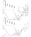
下記の図1〜3は、本明細書に説明の実施形態に使用するための、例示的な撮像システム及びハイパースペクトル・データキューブの説明を提供する。図4A〜4Cは、組織酸素付与の測定方法を示すフローチャートである。 1-3 below provide a description of an exemplary imaging system and hyperspectral data cube for use in the embodiments described herein. 4A to 4C are flowcharts showing a method for measuring tissue oxygenation.
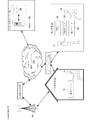
図1Aは、いくつかの実施態様による撮像デバイス100を含む分散診断環境10の実施例である。いくつかの実施態様における分散診断環境10は、一つ以上の臨床環境20、一つ以上の処理及び/または記憶センター50、及び、一つ以上のインターネット・サービス・プロバイダ60及び/または携帯電話会社40と共に、一つ以上の臨床環境20と一つ以上の処理及び/または記憶センター50との間での通信を可能にする、付随セル・タワー42を有する通信ネットワーク156を含む。
FIG. 1A is an example of a distributed
図1に示す臨床環境20は、本明細書に説明する改良型ハイパースペクトル撮像技術を利用することによって、多くの対象者22の需要に対応するように設計されている。いくつかの実施態様における臨床環境20は、対象者22の組織の一連の画像を採集するために撮像デバイス100を操作する医療専門家21を含む。いくつかの実施形態における臨床環境は、また、通信ネットワーク156を介して処理及び/または記憶センター50と通信する通信デバイス26を含む。いくつかの実施形態における臨床環境20は、処理及び/または記憶センター50に依存せずにハイパースペクトル画像を処理するための処理デバイス24を含む。いくつかの実施形態における臨床環境は、通信デバイス26及び処理デバイス24の両方を含む。
The
いくつかの実施態様における撮像デバイス100は、対象物(例えば、対象者22の体の一領域)を照明し、対象物の撮像データを生成する。いくつかの実施態様における撮像デバイス100は、一つ以上の光源120を使用して対象物を照明する。いくつかの実施態様においては、対象物を照明した後、またはそれと同時に、撮像デバイス100は、処理ハイパースペクトル画像を形成するために、対象物に対応する撮像データ(例えば、ハイパースペクトル画像データ・セット)を生成して処理及び/または記憶センター50へ送信する。他の実施態様における撮像デバイス100及び/または処理デバイス24は、画像データ・セットを使用して処理ハイパースペクトル画像を形成し、処理及び/または記憶センター50へ処理ハイパースペクトル画像を送信する。
The
いくつかの実施態様においては、撮像データのスペクトル解析が、例えば処理サーバ52を使用して、処理及び/または記憶センター50で実行される。いくつかの実施態様においては、スペクトル解析の記録が、処理及び/または記憶センター50でデータベース54内に形成される。いくつかの実施態様においては、スペクトル解析の記録及び/またはスペクトル解析に基づく生理的状態の指標が、処理及び/または記憶センター50から臨床環境20へ返信される。
In some embodiments, spectral analysis of the imaging data is performed at the processing and / or
いくつかの実施態様においては、画像キャプチャ及び画像処理は、対象者の関心領域の複数の画像を採集する撮像デバイス100を含む(例えば、第一のスペクトル帯域幅でキャプチャされた第一の画像及び第二のスペクトル帯域幅でキャプチャされた第二の画像)。撮像デバイス100は、各々の記憶域に各画像を保存する(例えば、第一の画像はメモリ220内の第一の位置に保存され、第二の画像はメモリ220内の第二の位置に保存される)。撮像デバイス100は、対象者の関心領域の複合(例えば、ハイパースペクトル、マルチスペクトル)画像を生成するために、ピクセル毎に(例えば、プロセッサ210で)各々の画像の各ピクセルに基づいて比較する。いくつかの実施態様においては、個々のピクセル値は、ピクセル毎の解析の前に、二値化、平均化または他の算術的処理がなされる。例えば、ピクセル毎の比較は、二値の、平均の、または算術処理のピクセル値の比較を含む。
In some embodiments, the image capture and image processing includes an
他の実施態様においては、例えば、撮像デバイス100及び/または処理デバイス24を使用して、臨床環境20でスペクトル解析が実行される。いくつかの実施態様においては、それから、スペクトル解析の記録及び/またはスペクトル解析に基づく生理的状態の指標が、臨床環境20から処理及び/または記憶センター50へ送信され、そこで、データベース54内に記録が形成される。いくつかの実施態様においては、臨床環境20内のローカル・データベースに、スペクトル解析の記録及び/または生理的状態の指標が形成される。いくつかの実施態様におけるローカル・データベースは、撮像デバイス100内にあり、任意で、後に異なるローカルまたは外部データベースへ伝送されてもよい。他の実施形態におけるローカル・データベースは、撮像デバイス100または処理デバイス24へ有線または無線で結線される。
In other embodiments, spectral analysis is performed in the
いくつかの実施態様においては、臨床環境で診察のために医療専門家21によって、スペクトル解析の記録及び/または生理的状態の指標が出力される。この医療専門家は、撮像デバイスを操作した医療専門家と同じまたは異なる者であってもよい。いくつかの実施態様においては、通信ネットワーク156を介して臨床環境20及び/または処理及び/または記憶センター50との通信状態にある通信デバイス72を含む外部診断環境70で、スペクトル解析の記録及び/または生理的状態の指標が出力される。
In some embodiments, spectral analysis records and / or physiological status indicators are output by medical professional 21 for examination in a clinical environment. The medical professional may be the same or different from the medical professional who operated the imaging device. In some embodiments, spectral analysis records and / or in an external
いくつかの実施態様における医療専門家21は、出力されたスペクトル解析または生理的状態の指標を吟味した後、対象者22に対して治療方針を指定する。いくつかの実施態様における治療は、撮像デバイス100を操作したのと同じ医療専門家21によって、生理的パラメータの指標を精査した医療専門家21によって、他の医療専門家21によって、または対象者22自身によって行われてもよい。
The medical professional 21 in some embodiments assigns a treatment policy to the subject 22 after examining the output spectral analysis or physiological condition indicators. Treatment in some embodiments may be performed by the same medical professional 21 who operated the
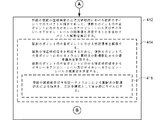
図1Bは、いくつかの実施態様による臨床診断環境20の概略図である。臨床診断環境20は、撮像デバイス100及び通信モジュール150を含む。通信モジュール150は、例えば任意で、遠隔位置へ撮像データを伝達する、撮像解析の記録及び/または生理的状態の指標を伝達する、及び/またはソフトウェア・アップデートまたは診断情報を受信するために使用される。
FIG. 1B is a schematic diagram of a clinical
いくつかの実施態様における撮像デバイス100は、対象者22の一体領域(例えば、対象者22の上肢24上の位置または下肢26上の位置)を照明し、その領域の撮像データを生成する。いくつかの実施態様における撮像デバイス100は、一つ以上の光源(120)を使用して対象者の体領域を照明する。そのような光源は、センサ・モジュール110が受ける反射光30を得るために、領域24によって反射される光28を放射する。センサ・モジュール100は、光センサ112及びフィルタ114を含む。
The
いくつかの実施形態においては、例えば、撮像デバイス100が、フィルタ・アレイに結合された光センサ・アレイを利用する場合、光センサ112からの出力は、インターフェイス・モジュール140のレジスタ142へ送信され、一つ以上のレジスタ・ルックアップ・テーブル144及び選択回路146によって処理される。例えば、いくつかの実施形態におけるルックアップ・テーブル144は、以下の方式で使用される。そのような実施形態においては、説明の目的で、レジスタ142は、複数のレジスタである。撮像デバイス100は、光センサ112の出力を受信するためにレジスタ142を使用し、制御モジュール130が、ルックアップ・テーブルを使用して、複数のレジスタ内のどのレジスタ142が、複数のフィルタ・タイプ内の特定のフィルタ・タイプのフィルタ・エレメントに対応するのかを特定する。制御モジュール130は、特定のフィルタ・タイプのフィルタ・エレメントに対応するレジスタの識別に基づき、複数のレジスタから光センサ出力の一つ以上のサブセットを選択する。それから、各々の画像がフィルタ・タイプに対応する独立画像を形成するために、光センサの独立サブセットが使用される。この目的のために、いくつかの実施態様においては、列選択及び行選択回路を使用してデータを選択するための選択制御回路146が存在する。このデータは、レジスタ142内に保存されて処理される。
In some embodiments, for example, if the
光源120、センサ・モジュール110及びインターフェイス・モジュール140の作動は、制御モジュール130の制御下にある。いくつかの実施形態においては、図1Bに示すように、制御モジュール130は順に、対象者22からの撮像データの取得を促進するために、通信モジュール150と相互作用する。
The operation of the
図2は、撮像デバイス100等の撮像デバイスの実施態様のブロック図である。特に、図2は、画像取得様式の特定の構成、例えば、図5及び6に関して説明されるビームステアリング実施形態、図7に関して説明される単一センサ実施形態、及び図8に関して説明される複数の光センサ実施形態での同時キャプチャに限られることはない。実際、図2は、以下に詳細に説明する方法に従って、例えば図4A〜4Cに説明する方法に従ってスペクトル画像の収集が可能な撮像デバイスのいずれの構成をも含む。
FIG. 2 is a block diagram of an embodiment of an imaging device such as
本明細書に説明する方法は、既知のハイパースペクトル/マルチスペクトル撮像システムまたは他の形態の撮像システムと共に利用できる。例えば一つの実施形態において、本明細書に説明する方法は、空間走査HSIシステムと併せて用いられる。空間走査HSIシステムは、完全なスペクトルが単一ピクセルまたは一行のピクセルで同時に取得される点走査及び線走査撮像システムを含む。そして測定器は、関心領域を通ってスキャンし、各ポイント(例えば、ピクセル)またはライン(例えば、一行のピクセル)で完全なスペクトルを順次採集する。別の実施形態においては、本明細書に説明する方法は、スペクトル走査HSIシステムと併せて用いられる。スペクトル走査HSIシステムは、二次元検出器で関心領域全体の画像を単一波長で取得する。測定器は、所定セットの波長の各々の波長として、関心領域全体の一連の画像を採集する。 The methods described herein can be used with known hyperspectral / multispectral imaging systems or other forms of imaging systems. For example, in one embodiment, the methods described herein are used in conjunction with a spatial scanning HSI system. Spatial scanning HSI systems include point scanning and line scanning imaging systems where a complete spectrum is acquired simultaneously with a single pixel or a row of pixels. The meter then scans through the region of interest and sequentially collects the complete spectrum at each point (eg, pixel) or line (eg, a row of pixels). In another embodiment, the methods described herein are used in conjunction with a spectral scanning HSI system. A spectral scanning HSI system acquires an image of the entire region of interest at a single wavelength with a two-dimensional detector. The meter collects a series of images of the entire region of interest as each wavelength of a predetermined set of wavelengths.
そのように図2は、本明細書内に開示される方式でハイパースペクトル画像シリーズの採集が可能なことを条件として、撮像デバイスの広い範囲を含む。そのように図2は、例として、本明細書内に開示される方法を実行するように適応された、下記に説明する図5〜8の撮像デバイスのいずれか、及び/または各々参照によりその全文が本明細書に援用される国際特許公開第WO2014/007869号、WO2013/184226、WO2014/063117及びWO2014/146053に開示された撮像デバイスのいずれかを表す。 As such, FIG. 2 includes a wide range of imaging devices, provided that hyperspectral image series can be collected in the manner disclosed herein. As such, FIG. 2 is illustratively any of the imaging devices of FIGS. 5-8 described below and / or each adapted to perform the methods disclosed herein, and / or each by reference thereto. It represents any of the imaging devices disclosed in International Patent Publication Nos. WO2014 / 007869, WO2013 / 184226, WO2014 / 063117 and WO2014 / 146053, the entire text of which is incorporated herein by reference.
いくつかの実施例の特徴が図2に示されているが、当業者は、簡潔さの目的で、また、本明細書に開示される実施例実施態様のより関連する態様を不明瞭にしないために、種々の他の特徴が示されていないことを本開示から理解すべきである。その目的で、撮像デバイス100は、一つ以上の中央処理ユニット(CPU)210、任意の主な不揮発性記憶ユニット209、任意のコントローラ208、不揮発性記憶ユニット209から任意でロードされるプログラム及びデータを含むシステム制御プログラム、データ及びアプリケーション・プログラムを記憶するためのシステムメモリ220を含む。いくつかの実施態様における不揮発性記憶ユニット209は、ソフトウェア及びデータを記憶するための、非一過性メディアのメモリ・カードまたは他の形態のものを含む。記憶ユニット209は、任意でコントローラ208によって制御される。
Although some example features are shown in FIG. 2, those skilled in the art will not obscure the more relevant aspects of the example embodiments disclosed herein for purposes of brevity. Thus, it should be understood from the present disclosure that various other features are not shown. For that purpose, the
いくつかの実施態様における撮像デバイス100は、一つ以上の入力デバイス204(例えば、タッチ・スクリーン、ボタンまたはスイッチ)及び/または任意のディスプレイ202を含むユーザー・インターフェイス200を任意で含む。加えて、かつ/または択一的に、いくつかの実施態様における撮像デバイス100は、ハンドヘルド・デバイス、スマートフォン(または同類のもの)、タブレット型コンピュータ、ラップトップ・コンピュータ、デスクトップ・コンピュータ及び/またはサーバ・システム等の外部デバイスによって制御されてもよい。その目的で、撮像デバイス100は、有線または無線外部デバイスもしくは通信ネットワーク(例えば、インターネット等の広域ネットワーク)156へ接続するための一つ以上の通信インターフェイス152を含む。いくつかの実施形態における撮像デバイス100は、非常にコンパクトで、ハンドヘルド・デバイス、スマートフォン(または同類のもの)、タブレット型コンピュータ及び/またはラップトップ・コンピュータへ、直接または電子インターフェイスによってドッキングする。いくつかの実施態様における撮像デバイス100は、(例えばドッキング・ステーションまたはUSB結合を介して、デスクトップ・コンピュータへドッキングする。撮像デバイス100は、前述のエレメントを相互接続させるための内部バス212を含む。通信バス212は、前述の構成部品間の通信を相互接続及び制御する回路(しばしばチップセットと呼ぶ)を含んでもよい。
The
いくつかの実施態様における撮像デバイス100は、通信ネットワーク156と交信することによって、通信ネットワーク、特に、セル方式、WiFi、ZigBee、Bluetooth(登録商標)、IEEE802.11b、802.11a、802.11gまたは802.11n等の無線リンクを伴うものを介して、撮像デバイス100がモバイル通信デバイスとの間でデータを送信及び/または受信することが可能になる。通信ネットワークは、データ通信を支持するように構成された適切な通信ネットワークであればよい。適切な通信ネットワークは、セル方式ネットワーク、広域ネットワーク(WAN)、ローカル・エリア・ネットワーク(LAN)、インターネット、IEEE802.11b、802.11a、802.11gまたは802.11n無線ネットワーク、地上通信線、ケーブル回線、光ファイバ回線、USB等を含むが、これらに限定されない。撮像システムは、実施形態または所望の機能に応じて、それ自体の計算力によって完全にオフラインで、ネットワーク上で生のデータまたは部分的に処理されたデータを送信することによって、または同時に両方式で作動可能である。
The
システムメモリ220は、DRAM、SRAM、DDRRAM(登録商標)または他のランダムアクセス固体メモリ・デバイス等の、高速ランダム・アクセス・メモリを含む。典型的に、不揮発性メモリ・フラッシュメモリ・デバイスまたは他の非一過性固体記憶デバイスを含む。システムメモリ220は、任意で、CPU(複数可)508から遠隔に位置する一つ以上の記憶デバイスを含む。システムメモリ220または代替的に、システムメモリ220内の非一過性メモリ・デバイス(複数可)は、非一過性コンピュータ可読記憶媒体を含む。
The
いくつかの実施態様においては、撮像デバイス100の作動は、CPU210によって実行されるオペレーティング・システム530によって主に制御される。オペレーティング・システム230は、システムメモリ220及び/または記憶ユニット209に保存できる。いくつかの実施形態における画像デバイス100は、オペレーティング・システムによって制御されず、むしろ、ハードウェア、ファームウェア及びソフトウェアの他の適切な組み合わせによって制御される。
In some embodiments, the operation of the
いくつかの実施態様においては、システムメモリ220は、本明細書に説明する種々のファイル及びデータ構造へのアクセスを制御するためのファイルシステム232、撮像デバイス100に結合及び/または統合された光源を制御するための照光ソフトウェア制御モジュール234、光センサ制御モジュール236、光センサ(例えば光センサ112)によって取得される243−1〜243N画像を含むハイパースペクトル画像シリーズA242を記憶するためのセンサ・データ・ストア240、取得センサ・データを操作するためのデータ処理ソフトウェア・モジュール250、取得ハイパースペクトル画像シリーズから組み立てた263−1〜263−Mのデータ平面を含むハイパースペクトル・データキューブAデータ262を記憶するためのハイパースペクトル・データキューブ・データ・ストア260、及び、外部デバイス(例えば、ハンドヘルド・デバイス、ラップトップ・コンピュータまたはデスクトップ・コンピュータ)及び/または通信ネットワーク(例えば、インターネット等の広域ネットワーク)に結合する通信インターフェイス152を制御するための通信インターフェイス・ソフトウェア制御モジュール154の一つ以上を含む。
In some embodiments, the
取得センサ・データ242及びハイパースペクトル・データキューブ・データ262は、システムメモリ220内の記憶モジュールに保存できるため、撮像デバイス100が任意の時間に実行する解析のステージに依存して同時に存在する必要はない。いくつかの実施態様においては、対象者を撮像する前に、また、取得センサ・データまたはその処理データ・ファイルを伝達した後、撮像デバイス100は、取得センサ・データ242もハイパースペクトル・データキューブ・データ262も含まない。いくつかの実施態様においては、対象者を撮像した後、また、取得センサ・データまたはその処理データ・ファイルを伝達した後、撮像デバイス100は、一時(例えば、記憶スペースが必要になるまで、所定時間など)取得センサ・データ242及び/またはハイパースペクトル・データキューブ・データ262を保持する。
いくつかの実施態様においては、上記の特定のプログラムまたはソフトウェア・モジュールは、上記の説明の機能を実行するための命令セットに対応する。命令セットは、一つ以上のプロセッサ、例えばCPU(複数可)210によって実行できる。上記の特定のソフトウェア・モジュールまたはプログラム(例えば、命令セット)は、分離型ソフトウェア・プログラム、プロシージャまたはモジュールとして具現する必要はないため、これらのプログラムまたはモジュールの種々のサブセットが組み合わされてもよい、または種々の実施形態に再編成されてもよい。いくつかの実施形態におけるシステムメモリ220は、上記の特定のモジュール及びデータ構造のサブセットを記憶する。さらに、システムメモリ220は、上記に説明のない追加モジュール及びデータ構造を記憶してもよい。
In some embodiments, the particular program or software module described above corresponds to an instruction set for performing the functions described above. The instruction set can be executed by one or more processors, such as CPU (s) 210. The particular software modules or programs (eg, instruction set) described above need not be embodied as separate software programs, procedures or modules, and various subsets of these programs or modules may be combined, Or it may be rearranged into various embodiments. The
システムメモリ220は、図2に図示しない一つ以上の以下のソフトウェア・モジュールも任意で含む。複数の病状のプロフィールを含むスペクトル・ライブラリ、測定スペクトル・データをスペクトル・ライブラリに比較するためのスペクトル解析ソフトウェア・モジュール、追加センサのための制御モジュール、(遠隔温度測定デバイス等の)一つ以上の追加センサによって取得される情報、スペクトル画像を生成するための画像構成ソフトウェア・モジュール、ハイパースペクトル・データキューブに基づいて組み立てられ、追加センサによって取得された情報に任意で融合されるスペクトル画像、追加センサによって取得されたデータをハイパースペクトル・データキューブ内へ集積化するための融合ソフトウェア制御モジュール、及び、ビルトイン・ディスプレイを制御するためのディスプレイ・ソフトウェア制御モジュール。
The
対象者及び/または対象者の視認スペクトル画像を吟味しながら、医師は、任意で画像デバイス100への、スペクトル画像及び/または診断出力の基礎となる一つ以上のパラメータを修正する入力を行うことができる。いくつかの実施態様におけるこの入力は、入力デバイス204を使用して行う。とりわけ、画像デバイスは、スペクトル・アナライザで選択されるスペクトル部分を修正する(例えば、解析感度の閾値を修正する)、または画像アセンブラで生成される画像の外観を修正する(例えば、輝度マップからトポロジカル・レンダリングへ切り替える)ように制御可能である。
While examining the subject and / or the subject's viewable spectral image, the physician optionally inputs to the
いくつかの実施態様における撮像デバイス100は、光センサ112の感知特性(例えば、露光設定、フレーム・レート、積算レートまたは検出される波長)を修正するように撮像サブシステムへ命令を伝達するよう指示できる。他のパラメータも修正できる。例えば、撮像デバイス100は、スクリーニングの目的で対象者の広視野画像を取得する、または特定関心領域の近接画像を取得するように指示可能である。
The
いくつかの実施態様における撮像デバイス100は、コントローラ208または記憶ユニット209を含まない。そのような実施態様におけるメモリ220及びCPU210は、一つ以上の特定用途向け集積回路チップ(ASIC)及び/またはプログラマブル・ロジック・デバイス(例えば、FGPA、フィールド・プログラマブル・ゲート・アレイ)である。例えば、いくつかの実施態様においては、ASIC及び/またはプログラム済みFPGAが、照光制御モジュール234、光センサ制御モジュール236及び/またはデータ処理モジュール250の命令を含む。いくつかの実施態様におけるASIC及び/またはFPGAは、さらに、取得センサ・データ・ストア240に対する記憶スペース、及びそこに記憶されるセンサ・データ242、及び/またはハイパースペクトル・データキューブ・データ・ストア260及びそこに記憶されるハイパースペクトル/マルチスペクトル・データキューブ262を含む。
The
いくつかの実施態様におけるシステムメモリ220は、画像デバイス100によって生成されたハイパースペクトル・データを、種々の生理的パラメータ及び/または病状に関連する既知のスペクトル・パターンと比較するために、スペクトル・ライブラリ及びスペクトル・アナライザを含む。いくつかの実施態様においては、取得ハイパースペクトル・データの解析は、ハンドヘルド・デバイス、タブレット型コンピュータ、ラップトップ・コンピュータ、デスクトップ・コンピュータ、外部サーバ等の外部デバイスで、または例えばクラウド・コンピューティング環境もしくは処理及び/または記憶センター50内で実行される。
The
いくつかの実施態様においては、スペクトル・ライブラリは、複数の生理的動脈パラメータ及び/または病状に関するプロフィールを含み、それらの各々が、一セットの、病状にユニークなスペクトル特徴を含む。スペクトル・アナライザは、測定ハイパースペクトル・データキューブに対応する対象者領域が、生理的パラメータ及び/または病状で冒されている確率を判定するためにスペクトル特徴を使用する。いくつかの実施態様における各々のプロフィールは、生理的パラメータ及び/または病状に関する付加情報、例えば、病状が悪性または良性かの情報、治療オプション、その他を含む。いくつかの実施態様における各々のプロフィールは、生体情報、例えば、異なる皮膚タイプの対象者に対する検出条件の修正に使用される情報を含む。いくつかの実施態様におけるスペクトル・ライブラリは、単一のデータベース内に保存される。他の実施態様においては、それに替えて、そのようなデータは、同じコンピュータにすべてを載せてもよい複数のデータベース内に、または同じコンピュータに載せてはいけないため、例えば、広域ネットワークによってアドレス指定可能な2台以上のコンピュータ上に保存される。いくつかの実施態様におけるスペクトル・ライブラリは、記憶ユニット220内に電子的に記憶され、ハイパースペクトル・データキューブ・データの解析中に必要な場合、コントローラ208を使用して読み出される。
In some embodiments, the spectral library includes profiles for a plurality of physiological arterial parameters and / or medical conditions, each of which includes a set of spectral features that are unique to the medical condition. The spectrum analyzer uses the spectral features to determine the probability that the subject area corresponding to the measured hyperspectral data cube is affected by physiological parameters and / or medical conditions. Each profile in some embodiments includes additional information regarding physiological parameters and / or medical conditions, such as information about whether the medical condition is malignant or benign, treatment options, etc. Each profile in some embodiments includes biometric information, eg, information used to modify detection conditions for subjects of different skin types. The spectral library in some embodiments is stored in a single database. In other embodiments, such data may instead be addressed in multiple databases, which may all be on the same computer, or on the same computer, for example by a wide area network. Stored on two or more computers. The spectral library in some embodiments is stored electronically in the
いくつかの実施態様におけるスペクトル・アナライザは、所定の生理的動脈パラメータ及び/または病状のスペクトル特徴を、確定スペクトル域内の対象者のスペクトルと比較することによって、ハイパースペクトル・データキューブ・データ由来の特定のスペクトル、所定スペクトル域を有するスペクトル(例えば、特定の生理的動脈パラメータ及び/または病状に対して特定のスペクトル域)を解析する。いくつかの実施態様における所定スペクトル域は、患者の組織(例えば、対象者22の体の領域24または26)のデオキシヘモグロビン・レベル、オキシヘモグロビン・レベル、全ヘモグロビン・レベル、酸素飽和、酸素灌流、水分補給レベル、全ヘマトクリット・レベル、メラニン・レベル及びコラーゲン・レベルの、一つ以上の値に対応する。確定スペクトル域内のみでそのような比較を実行することは、特徴づけの精度を向上させると共に、そのような特徴づけの実行に必要な演算電力を減少させることができる。
In some embodiments, the spectrum analyzer identifies the derived from hyperspectral data cube data by comparing predetermined physiological arterial parameters and / or spectral characteristics of the medical condition with the spectrum of the subject within the deterministic spectral range. Spectrum having a predetermined spectral range (eg, a specific spectral range for a specific physiological artery parameter and / or medical condition). In some embodiments, the predetermined spectral range is deoxyhemoglobin level, oxyhemoglobin level, total hemoglobin level, oxygen saturation, oxygen perfusion of patient tissue (eg,
いくつかの実施態様における生理的パラメータは、血流(例えば、血液流入及び/または流出)、酸素供給、酸素利用率、酸素飽和度、デオキシヘモグロビン・レベル、オキシヘモグロビン・レベル、全ヘモグロビン・レベル、酸素灌流、水分補給レベルと全ヘマトクリット・レベルからなる群から選択される動脈パラメータである。 In some embodiments, the physiological parameters include blood flow (eg, blood inflow and / or outflow), oxygen supply, oxygen utilization, oxygen saturation, deoxyhemoglobin level, oxyhemoglobin level, total hemoglobin level, An arterial parameter selected from the group consisting of oxygen perfusion, hydration level and total hematocrit level.
いくつかの実施態様における病状は、末梢動脈疾患(PAD)、重症虚血肢、潰瘍、壊疽、組織虚血、潰瘍形成、潰瘍進行、褥瘡形成、褥瘡進行、糖尿病性足部潰瘍形成、糖尿病性足部潰瘍進行、静脈うっ血、静脈潰瘍疾患、感染、ショック、心不全、呼吸不全、血液量減少、糖尿病の進行、うっ血性心不全、敗血症、脱水、出血、高血圧、高等血糖最終生成物(AGE)の検出、化学薬品または生物製剤への曝露、及び炎症反応からなる群から選択される。 The pathology in some embodiments is peripheral arterial disease (PAD), severe ischemic limbs, ulcers, gangrene, tissue ischemia, ulceration, ulcer progression, pressure ulcer formation, pressure ulcer progression, diabetic foot ulceration, diabetic Foot ulcer progression, venous congestion, venous ulcer disease, infection, shock, heart failure, respiratory failure, blood loss, diabetes progression, congestive heart failure, sepsis, dehydration, bleeding, hypertension, hyperglycemic end product (AGE) Selected from the group consisting of detection, exposure to chemicals or biologics, and inflammatory response.
いくつかの実施態様におけるスペクトル・アナライザは、患者の生理的パラメータ及び/または病状に対応するハイパースペクトル・データキューブ内のスペクトル・シグネチャを特定する。特定の実施態様において、これは、患者の組織に関連する組織内の酸化または水分補給パターンを識別することによって達成される。いくつかの実施態様におけるハイパースペクトル・データキューブの解析は、ハイパースペクトル・データキューブ内の各々のデジタル画像の少なくとも一つ(例えば、波長範囲番号Mのデータキューブ平面362−M)の輝度を調節すること、ハイパースペクトル・データキューブ内の各々のデジタル画像の少なくとも一つのコントラストを調節すること、ハイパースペクトル・データキューブ内の各々のデジタル画像の少なくとも一つからアーティファクトを取り除くこと、ハイパースペクトル・データキューブ内の各々のデジタル画像の少なくとも一つの一つ以上のサブピクセルを処理すること、及び、複数のデジタル画像から組み立てられたスペクトル・ハイパーキューブを変形することの、少なくとも一つを実行することを含む。 The spectrum analyzer in some embodiments identifies a spectral signature in the hyperspectral data cube that corresponds to the patient's physiological parameters and / or medical condition. In certain embodiments, this is accomplished by identifying a tissue oxidation or hydration pattern associated with the patient's tissue. Analysis of the hyperspectral data cube in some embodiments adjusts the brightness of at least one of each digital image in the hyperspectral data cube (eg, data cube plane 362-M for wavelength range number M). Adjusting at least one contrast of each digital image in the hyperspectral data cube, removing artifacts from at least one of each digital image in the hyperspectral data cube, in the hyperspectral data cube Performing at least one of processing at least one subpixel of each of the digital images and transforming a spectral hypercube assembled from the plurality of digital images.
いくつかの実施態様におけるディスプレイ202は、(例えば、出力モジュールから)生理的パラメータ及び/または病状の指標を受信し、その生理的パラメータ及び/または病状の指標を表示する。いくつかの実施形態においては、出力モジュールは、一般的なディスプレイ制御モジュールである。いくつかの実施態様におけるディスプレイ202は、ディスプレイ制御モジュールから画像(例えば、カラー画像、単一波長画像またはハイパースペクトル/マルチスペクトル画像)を受信し、その画像を表示する。任意で、ディスプレイ・サブシステムも、付加情報を含むレジェンドを表示する。例えば、レジェンドは、領域が特定の病状を有する確率を示す情報、病状のカテゴリー、病状の推定年齢、病状の境界線、病状の治療に関する情報、検査が必要であろう新しい関心領域を示す情報、及び/または診断を得るのに有益であろう新情報を示す情報、例えば、別のテストまたは解析可能な別のスペクトル領域を表示できる。 The display 202 in some embodiments receives a physiological parameter and / or medical condition indicator (eg, from an output module) and displays the physiological parameter and / or medical condition indicator. In some embodiments, the output module is a generic display control module. The display 202 in some embodiments receives an image (eg, color image, single wavelength image or hyperspectral / multispectral image) from the display control module and displays the image. Optionally, the display subsystem also displays a legend containing additional information. For example, the legend may include information that indicates the probability that the region has a particular medical condition, the category of the medical condition, the estimated age of the medical condition, information about the boundary of the medical condition, treatment of the medical condition, information that indicates a new area of interest that may need to be examined, And / or information indicating new information that may be useful in obtaining a diagnosis, eg, another spectral region that can be tested or analyzed.
いくつかの実施態様においては、撮像デバイス100のハウジング内へハウジング・ディスプレイが構築される。そのような実施態様の実施例には、プロセッサ210と電子通信状態にあるビデオ・ディスプレイが含まれる。いくつかの実施態様におけるハウジング・ディスプレイは、表示画像を操作するために、及び/または画像デバイス100を制御するために使用可能なタッチ・スクリーン・ディスプレイである。
In some embodiments, a housing display is built into the housing of the
いくつかの実施態様における通信インターフェイス152は、モバイル・デバイス・ディスプレイを有するモバイル・デバイスのためのドッキング・ステーションを含む。スマートフォン、パーソナル・デジタル・アシスタント(PDA)、エンタープライズ・デジタル・アシスタント、タブレット型コンピュータ、IPOD(登録商標)、デジタルカメラ、ポータブル音楽プレーヤまたはウェアラブル技術デバイス等のモバイル・デバイスは、ドッキング・ステーションへ結合できるため、撮像デバイス100上へモバイル・デバイス・ディスプレイを有効に取り付けることができる。任意で、モバイル・デバイスは、表示画像を操作するために、及び/または画像デバイス100を制御するために使用される。
いくつかの実施態様における撮像デバイス100は、例えば、ハンドヘルド・デバイス、タブレット型コンピュータ、ラップトップ・コンピュータ、デスクトップ・コンピュータ、テレビ、IPOD、プロジェクタ・ユニットまたはウェアラブル技術デバイス上の外部ディスプレイと有線または無線通信可能に構成され、外部ディスプレイ上に画像が表示される。任意で、外部デバイス上のユーザー・インターフェイスは、表示画像を操作するために、及び/または撮像デバイス100を制御するために使用される。
The
いくつかの実施態様においては、ディスプレイ上にリアルタイムで画像が表示可能である。リアルタイム画像は、例えば、対象者の画像に焦点を合わせる、適切な関心領域を選択する、及び対象者の画像へズームインまたはズームアウトするために使用できる。一つの実施形態における対象者のリアルタイム画像は、検出器フィルタで覆われていない光学式検出器でキャプチャされるカラー画像である。いくつかの実施態様における撮像サブシステムは、対象者の真のカラー画像をキャプチャするための専用光学式検出器を含む。いくつかの実施態様における対象者のリアルタイム画像は、検出器フィルタに覆われた光学式検出器でキャプチャされる単一波長または狭帯域(例えば、10〜50nm)画像である。これらの実施形態においては、撮像サブシステム内の検出器フィルタで覆われるいずれの光学式検出器が、以下の目的で使用されてもよい。(i)ハイパースペクトル・データキューブ内への統合化のために対象者のデジタル画像を解像すること、及び(ii)焦点合わせのために狭帯域画像を解像すること、またはそうでなければ、撮像デバイス100の光学特性を操作すること。
In some embodiments, the image can be displayed in real time on the display. Real-time images can be used, for example, to focus on the subject's image, select an appropriate region of interest, and zoom in or out on the subject's image. The real-time image of the subject in one embodiment is a color image captured with an optical detector that is not covered by a detector filter. The imaging subsystem in some embodiments includes a dedicated optical detector for capturing a true color image of the subject. The real-time image of the subject in some embodiments is a single wavelength or narrow band (eg, 10-50 nm) image captured with an optical detector covered by a detector filter. In these embodiments, any optical detector covered with a detector filter in the imaging subsystem may be used for the following purposes. (I) resolving a subject's digital image for integration into a hyperspectral data cube; and (ii) resolving a narrowband image for focusing, or otherwise Manipulating the optical properties of the
いくつかの実施態様においては、生理的パラメータ及び病状の指標、及び/または光センサ112でキャプチャされたデータから構築したハイパースペクトル画像は、内部ハウジング・ディスプレイ、装着ハウジング・ディスプレイまたは外部ディスプレイ上に表示される。(例えば、ハイパースペクトル/マルチスペクトル・データキューブ内に存在する)組立ハイパースペクトル・データは、一つ以上のパラメータ(例えば、生理的動脈パラメータ)に基づき、撮像対象物または対象者の二次元表現を形成するために使用される。撮像システムメモリまたは外部デバイス内に記憶された画像コンストラクタ・モジュールは、例えば、一つ以上の解析スペクトルに基づき画像を構築する。具体的には、画像コンストラクタは、一つ以上のスペクトル内で情報の表現を形成する。一つの実施例における画像コンストラクタは、二次元輝度マップを構築する。このマップ内では、一つ以上のスペクトル内の一つ以上の特定波長(または波長範囲)の空間的に異なる輝度は、可視標識の対応する空間的に異なる輝度によって表される。
In some embodiments, a hyperspectral image constructed from physiological parameters and disease state indicators and / or data captured by
いくつかの実施態様における画像コンストラクタは、一つ以上の追加センサから取得された情報に、ハイパースペクトル画像を融合する。適切な画像融合法の非限定的実施例は、帯域オーバレイ、高域通過フィルタ法、輝度彩色飽和、主成分解析及び離散ウェーブレット変換を含む。 The image constructor in some embodiments fuses the hyperspectral image to information obtained from one or more additional sensors. Non-limiting examples of suitable image fusion methods include band overlay, high pass filter method, luminance color saturation, principal component analysis and discrete wavelet transform.
図3は、ハイパースペクトル・データキューブ262を示す概略図である。ハイパースペクトル・センサは、ハイパースペクトル・データキューブ平面263と称する一セットの画像として情報を採集する。各々の画像263は、電磁スペクトルの範囲を表し、スペクトル帯域としても知られている。これらの画像263は、それから組み合わされて、処理及び解析のための三次元ハイパースペクトル・データキューブ262を形成する。
FIG. 3 is a schematic diagram illustrating the
図4A〜4Bは、組織酸素付与の測定方法400を示すフローチャートである。方法400は、一つ以上のプロセッサ及びメモリを有する電子デバイスで実行される。いくつかの実施態様においては、方法の一つ以上のステップは、撮像システム(例えば、図1の撮像システム100、図5の、ビームステアリング・エレメントを利用する同軸撮像システム500、図7の、光センサ及びフィルタ・アレイを利用する単一センサ撮像システム700、または図8の同時キャプチャ撮像システム800)で実行される。
4A-4B are flowcharts illustrating a tissue
電子デバイス(例えば、コンピュータまたは撮像システム)は、関心組織の複数の画像(例えば、画像231)を含むデータ・セット(例えば、ハイパースペクトル画像シリーズ242またはハイパースペクトル・データキューブ262)を取得する(402)。複数の画像内の各画像は、8〜12のスペクトル帯の所定のセット内の異なるスペクトル帯で解像され、ピクセル値のアレイを含む。例えば、いくつかの実施形態においては、各画像は、500,000以上のピクセル値、1,000,000以上のピクセル値、1,100,000以上のピクセル値、1,200,000以上のピクセル値、または1,300,000以上の測定ピクセル値を含む。いくつかの実施態様におけるハイパースペクトル・データ・セットは、また、所定セットの8〜10のスペクトル帯のもの以外のスペクトル帯で解像された画像からのデータ(例えば、本明細書に説明の処理ステップに含まれないデータ)を含む。
An electronic device (eg, a computer or imaging system) obtains a data set (eg,
いくつかの実施態様における方法は、撮像システム(例えば、図1の撮像システム100、図5の、ビームステアリング・エレメントを利用する同軸撮像システム500、図7の、光センサ及びフィルタ・アレイを利用する単一センサ撮像システム700、または図8の同時キャプチャ撮像システム800)で関心組織の複数の画像をキャプチャすること(404)を含む。
The method in some embodiments utilizes an imaging system (eg, the
いくつかの実施態様における撮像システムは、(例えば、図7の、光センサ及びフィルタ・アレイを利用する単一センサ撮像システム700、または図8の、八つ以上の画像センサを利用する同時キャプチャ撮像システム800を使用する場合)同時に複数の画像のすべてをキャプチャする(406)。
In some embodiments, the imaging system (e.g., a single
いくつかの実施態様におけるハイパースペクトル撮像システムは、第一の時点で同時に、複数の画像の第一のサブセットをキャプチャし(408)、第一の時点以外の第二の時点に、複数の画像の第二のサブセットをキャプチャする。例えば、同時キャプチャ撮像システム(例えば、図8のシステム800)は、光センサ112−1〜112−4で各々一つずつ、四つの画像を同時にキャプチャする。このとき、各々の画像は、第一のキャプチャ・イベントにおいて所定セットの8〜10のスペクトル帯内の異なるスペクトル帯でキャプチャされる。それから同時キャプチャ撮像システムは、光センサ112−1〜112−4で各々一つずつ、さらに四つの画像を同時にキャプチャする。このとき、各々の画像は、第二のキャプチャ・イベントにおいて所定セットの8〜10のスペクトル帯内の異なるスペクトル帯でキャプチャされる。そのように、同時キャプチャ撮像システムは、第一及び第二のキャプチャ・イベント間で、所定セットの8〜10のスペクトル帯の八つで画像をキャプチャする。いくつかの実施態様においては、所定セットの8〜12のスペクトル帯のすべてにおいて画像をキャプチャするために、四つ以上のキャプチャ・イベント(例えば、三つ、四つまたは五つのキャプチャ・イベント)を用いてもよい。
In some embodiments, the hyperspectral imaging system captures (408) a first subset of the plurality of images simultaneously at the first time point, and at a second time point other than the first time point, Capture the second subset. For example, a simultaneous capture imaging system (eg,
いくつかの実施態様においては、ハイパースペクトル画像を採集することが、対象者の組織を第一の光(例えば、図1B、5、6及び8に示す光源120)で照明することを含み、第一の光は、所定セットのスペクトル帯内の、第一のサブセットのスペクトル帯を含む。いくつかの実施態様において、関心領域の照明に使用される光は、撮像システムで検出される後方散乱光のSN比を向上させるために偏光される。検出器の前で、照射光の偏光に対して直角に偏光フィルタを使用することは、検出信号から無偏光環境光を減少させる。
In some embodiments, collecting the hyperspectral image includes illuminating the subject's tissue with a first light (eg,
いくつかの実施態様において、ハイパースペクトル画像をキャプチャすることは、キャプチャされるスペクトル帯に対応する光で照明しながら、複数の画像内の、第一のサブセットの画像を同時にキャプチャすることを含み、第一の複数の画像内の各画像は、第一の複数のスペクトル帯内のユニークなスペクトル帯でキャプチャされる。言い換えれば、画像は、関心領域が、マッチする光で照明されている間に複数のスペクトル帯でキャプチャされる。 In some embodiments, capturing the hyperspectral image includes simultaneously capturing a first subset of images in the plurality of images while illuminating with light corresponding to the captured spectral band; Each image in the first plurality of images is captured in a unique spectral band within the first plurality of spectral bands. In other words, the image is captured in multiple spectral bands while the region of interest is illuminated with matching light.
いくつかの実施態様においては、第一のサブセットの画像内の各画像(例えば、図2のハイパースペクトル画像シリーズA242内の各画像234)は、複数の光学式検出器内のユニークな光学式検出器(例えば、図8に示す同時キャプチャ撮像システム800内の各々の光学式検出器112)でキャプチャされる。例えば、いくつかの実施形態において、各々の光学式検出器112は、各々のフィルタ114で覆われ、第一の複数のスペクトル帯内のユニークなスペクトル帯に対応する光を検出器112へ通過させる。この様式において、光学式検出器112の各々で同時に採集された画像は、画像シリーズA242の一部または全部を形成するために組み合わされる。
In some embodiments, each image in the first subset of images (eg, each
いくつかの実施態様においては、例えば、第一の光で照明されながら、対象者の画像が、所定セットのスペクトル帯内のすべての波長よりも少なくキャプチャされる場合、方法は、さらに、第二の光(例えば、図1B、5、6及び8に示す光源120)で組織を照明することを含み、第二の光は、所定セットのスペクトル帯内の、第二のサブセットのスペクトル帯を含む。例えば、第二のサブセットのスペクトル帯は、第一のサブセットのスペクトル帯以外のものである。
In some embodiments, for example, if the subject's image is captured less than all wavelengths in the predetermined set of spectral bands while illuminated with the first light, the method further includes the second Illuminating the tissue with light (eg,
いくつかの実施態様における第一の光及び第二の光は、別個の光源から照射される。いくつかの実施態様において、関心領域の照明に使用される光は、撮像システムで検出される後方散乱光のSN比を向上させるために偏光される。検出器の前で、照射光の偏光に対して直角の偏光フィルタを使用することは、検出信号から、無偏光環境光及び、被撮像面からの直接反射光を減少させる。 The first light and the second light in some embodiments are emitted from separate light sources. In some embodiments, the light used to illuminate the region of interest is polarized to improve the signal to noise ratio of backscattered light detected by the imaging system. Using a polarization filter perpendicular to the polarization of the illumination light in front of the detector reduces unpolarized ambient light and direct reflected light from the imaged surface from the detection signal.
いくつかの実施態様において、ハイパースペクトル画像を採集することは、第二の光で照明しながら、対象者の関心領域の複数の画像内の第二のサブセットの画像(例えば、図2に示す画像シリーズA242内の画像243)を同時に採集することを含み、第二のサブセットの画像内の各画像は、第二のサブセットのスペクトル帯内のユニークなスペクトル帯で採集される。言い換えれば、第二のセットの画像は、関心領域が、マッチする光で照明されている間に複数のスペクトル帯で採集される。第二のセットの画像は、ハイパースペクトル画像シリーズ(例えば、図2に示すシリーズA242)に必要なすべての画像が、第一及び第二のセットの画像間で採集されるように第一のセットの画像を補完する。
In some embodiments, collecting the hyperspectral image comprises illuminating with a second light, and a second subset of images within the plurality of images of the subject's region of interest (eg, the image shown in FIG. 2). Each image in the second subset of images is collected in a unique spectral band within the second subset of spectral bands, including simultaneously collecting images 243) in series A242. In other words, the second set of images is collected in multiple spectral bands while the region of interest is illuminated with matching light. The second set of images is the first set so that all images required for the hyperspectral image series (eg,
いくつかの実施態様において、第一のサブセットの画像内の各画像は、複数の光学式検出器内のユニークな光学式検出器で採集され、第二のサブセットの画像内の各画像は、複数の光学式検出器内のユニークな光学式検出器で採集され、複数の光学式検出器内の少なくとも一つの光学式検出器が、第一のサブセットの画像内の対応画像及び第二のサブセットの画像内の対応画像を採集する。言い換えれば、いくつかの実施態様においては、複数の撮像センサを有する撮像システム(例えば、図8に示す同時キャプチャ撮像システム800)が使用され、光学式検出器の少なくとも一つ(例えば、図8の光学式検出器112−1)が、第一のスペクトル帯で、(例えば、第一のサブセットの画像内の)第一の画像、それから第二のスペクトル帯で、(例えば、第二のサブセットの画像内の)第二の画像を採集するために使用される。
In some embodiments, each image in the first subset of images is collected with a unique optical detector in the plurality of optical detectors, and each image in the second subset of images is captured in the plurality of images. Collected by a unique optical detector in the plurality of optical detectors, wherein at least one optical detector in the plurality of optical detectors has a corresponding image in the first subset image and a second subset in the image. Collect the corresponding image in the image. In other words, in some embodiments, an imaging system having multiple imaging sensors (eg, a simultaneous
いくつかの実施形態における光学式検出器(例えば、図8に示す光学式検出器112−1)は、第一のスペクトル帯の光及び第二のスペクトル帯の光を光学式検出器へ通過させるデュアル帯域フィルタ(例えば、図8に示すフィルタ114−1)で覆われる。この様式で、対象者の関心領域は、最初に、第二のスペクトル帯ではない第一のスペクトル帯を含む光で照明され、第一の画像が光学式検出器(例えば、図8に示す光学式検出器112−1)でキャプチャされる。その後、対象者の関心領域は、第一のスペクトル帯ではない第二のスペクトル帯を含む光で照明され、第二の画像が光学式検出器(例えば、図8に示す同じ光学式検出器112−1)でキャプチャされる。したがって、ハイパースペクトル画像シリーズの二つの画像(例えば、図2に示す画像シリーズA242内の画像243−B及び画像243−C)を採集するために、光学式検出器(例えば、図8に示す光学式検出器112−1)が、異なるスペクトル帯で使用される。
The optical detector in some embodiments (eg, optical detector 112-1 shown in FIG. 8) passes light in the first spectral band and light in the second spectral band to the optical detector. It is covered with a dual band filter (for example, filter 114-1 shown in FIG. 8). In this manner, the region of interest of the subject is first illuminated with light that includes a first spectral band that is not the second spectral band, and a first image is detected by an optical detector (eg, the optical shown in FIG. 8). Captured by equation detector 112-1). Thereafter, the region of interest of the subject is illuminated with light that includes a second spectral band that is not the first spectral band, and the second image is an optical detector (eg, the same
いくつかの実施態様において、複数の光学式検出器内の各光学式検出器(例えば、図8に示す光学式検出器112−1〜112−4の各々)は、第一のサブセットの画像内の対応画像及び第二のサブセットの画像内の対応画像を採集する(428)。いくつかの実施態様において、各々の光学式検出器(例えば、図8に示す光学式検出器112)は、ユニークなデュアル帯域フィルタ(例えば、図8に示すフィルタ114)で覆われる。この様式において、対象者の関心領域は、フィルタの各々の通過帯の一つに対応するスペクトル帯を有する第一の光で照明されるが、フィルタの各々の他の通過帯に対応するスペクトル帯を有する光(例えば、第一の光源120−1から放射された光)では照明されない。その位置が第一の光で照明されている間に、第一のサブセットの画像が採集される。その後、その位置は、フィルタの各々の他のスペクトル通過帯に対応するスペクトル帯を有する第二の光で照明されるが、フィルタの各々の第一の通過帯に対応する波長を有する光(例えば、第二の光源120−2から放射された光)では照明されない。それから、その位置が第二の光で照明されている間に第二のサブセットの画像が採集される。
In some embodiments, each optical detector in the plurality of optical detectors (eg, each of the optical detectors 112-1 to 112-4 shown in FIG. 8) is in a first subset of images. And corresponding images in the second subset of images (428). In some embodiments, each optical detector (eg,
いくつかの実施態様における第一のサブセットの画像は、四つの画像であり、第二のサブセットの画像も四つの画像である。例えば、いくつかの実施態様においては、四つの光学式検出器を有する撮像システム(例えば、図8に示す同時キャプチャ撮像システム800)が使用される。各々の光学式検出器(例えば、光学式検出器112)が、第一のサブセット内の画像及び第二のサブセット内の画像を採集し、八つの画像から構成されるハイパースペクトル画像シリーズを形成する。
The images of the first subset in some embodiments are four images, and the images of the second subset are also four images. For example, in some implementations, an imaging system having four optical detectors (eg, a simultaneous
いくつかの実施態様において、複数の光学式検出器内の各光学式検出器(例えば、図8に示す同時キャプチャ撮像システム800等のハイパースペクトル撮像システムの光学式検出器112)は、デュアル帯域フィルタ(例えば、図800に示すフィルタ114)で覆われる。
In some embodiments, each optical detector in the plurality of optical detectors (eg,
いくつかの実施態様において、各光学式検出器は、トリプル帯域フィルタで覆われ、第三の光源の使用、及びユニークなスペクトル帯での3セットの画像の収集が可能となる。例えば、四つの光学式検出器は、各検出器がトリプル帯域フィルタで覆われた場合、最高12のユニークなスペクトル帯で画像を採集することが可能である。 In some embodiments, each optical detector is covered with a triple band filter, allowing the use of a third light source and the collection of three sets of images in a unique spectral band. For example, four optical detectors can collect images in up to 12 unique spectral bands, where each detector is covered with a triple band filter.
いくつかの実施態様において、各光学式検出器は、クワッド帯域フィルタで覆われ、第四の光源の使用、及びユニークなスペクトル帯での4セットの画像の収集が可能となる。例えば、四つの光学式検出器は、各検出器がクワッド帯域フィルタで覆われた場合、最高16のユニークなスペクトル帯で画像を採集することが可能である。さらに他の実施態様においては、各々5、6、7、それ以上の帯域の通過を許容する帯域フィルタが、ユニークなスペクトル帯に関してより大きなセットを採集するために使用することができる。 In some embodiments, each optical detector is covered with a quad band filter, allowing the use of a fourth light source and collecting four sets of images in a unique spectral band. For example, four optical detectors can collect images in up to 16 unique spectral bands, where each detector is covered with a quad band filter. In still other embodiments, bandpass filters that allow the passage of 5, 6, 7, or more bands each can be used to collect a larger set of unique spectral bands.
方法は、さらに、組織の複数の登録画像を形成するために、プロセッサを使用してピクセル毎に複数の画像を登録すること(411)を含む。いくつかの実施態様において、登録することは、各画像を、対応する記憶域に(例えば、メモリ220内に)記憶すること、及び、複数の登録画像を生成するために、各々の画像の各ピクセルを(例えば、プロセッサ210で)ピクセル毎に比較することを含む。いくつかの実施態様において、一つ以上の登録画像は、それから、対応する記憶域に記憶される。 The method further includes registering (411) a plurality of images per pixel using a processor to form a plurality of registered images of the tissue. In some embodiments, registering stores each image in a corresponding storage area (eg, in memory 220) and generates each of the images to generate a plurality of registered images. Comparing the pixels pixel by pixel (eg, in processor 210). In some embodiments, one or more registered images are then stored in a corresponding storage area.
いくつかの(例えば、方法が、撮像システムで画像をキャプチャすることを含む)実施態様における方法は、撮像システム100でスペクトル解析を実行する(例えば、システムは画像をキャプチャして処理する)ことを含む。他の実施態様における撮像システム100は、画像をキャプチャしてから、スペクトル解析のために、その画像を、または予め処理したデータ(例えば、ハイパーキューブ)を外部処理デバイス(例えば、ローカル処理デバイス24または遠隔処理サーバ52)へ送信する。
A method in some embodiments (eg, the method includes capturing an image with an imaging system) performs spectral analysis with the imaging system 100 (eg, the system captures and processes the image). Including. In other embodiments, the
電子デバイスは、それから、組織の複数の登録画像の二次元領域内における複数のポイントで、スペクトル解析を実行する(412)(例えば、所定セットのスペクトル帯でキャプチャされた各画像内の、同じポイントまたはポイントのグループにおける吸光度を評価する)。このスペクトル解析は、複数のポイント内の各ポイントにおけるオキシヘモグロビン・レベル及びデオキシヘモグロビン・レベルの概算値を決定することを含む。 The electronic device then performs a spectral analysis at a plurality of points within a two-dimensional region of the plurality of registered images of tissue (412) (eg, the same point within each image captured in a predetermined set of spectral bands). Or assess absorbance in groups of points). This spectral analysis includes determining approximate values of oxyhemoglobin level and deoxyhemoglobin level at each point in the plurality of points.
いくつかの実施態様におけるデバイスは、複数のポイント内の各ポイントにおける吸収信号を解決する(414)こと、複数の補正吸収信号を形成するために、複数のポイント内の各ポイントにおけるメラニン貢献及び散漫散乱からの信号損失を計算すること、及び、複数のポイント内の各ポイントにおける補正吸収信号からオキシヘモグロビン・レベル及びデオキシヘモグロビン・レベルの概算値を決定することによってスペクトル解析を実行する。 The device in some embodiments resolves (414) the absorption signal at each point in the plurality of points, melanin contribution and diffusion at each point in the plurality of points to form a plurality of corrected absorption signals. Spectral analysis is performed by calculating the signal loss from scatter and determining approximate values for oxyhemoglobin and deoxyhemoglobin levels from the corrected absorption signal at each point in the plurality of points.
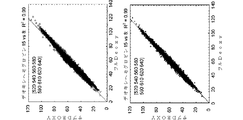
ハイパースペクトル・データからオキシヘモグロビン及びデオキシヘモグロビンを判定するためのアルゴリズムは、本技術において知られる。例えば、例示的な処理アルゴリズムは、すべての目的のために参照によって全文が本開示に援用される米国特許第8,644,911号に説明されている。有利に、本開示は、当該技術分野で開示されたアルゴリズムを使用する場合、有意に少ない波長で(例えば、15以上ではなく、8〜10の波長を使用して)正確な測定を促進することによって、オキシヘモグロビン・レベル及びデオキシヘモグロビンを判定するための演算負荷を減少させる。 Algorithms for determining oxyhemoglobin and deoxyhemoglobin from hyperspectral data are known in the art. For example, an exemplary processing algorithm is described in US Pat. No. 8,644,911, which is incorporated herein by reference in its entirety for all purposes. Advantageously, the present disclosure facilitates accurate measurements at significantly fewer wavelengths (eg, using 8-10 wavelengths rather than 15) when using algorithms disclosed in the art. Reduces the computational load for determining oxyhemoglobin levels and deoxyhemoglobin.
いくつかの実施態様における電子デバイス(例えば、撮像デバイス100、ローカル処理デバイス24または遠隔処理サーバ52)は、複数の組織酸素付与測定へのメラニンによる貢献及び散漫散乱による損失(例えば、背景貢献)を、集合的に二次多項式としてモデル化する(416)。例えば、米国特許第8,644,911号は、メラニンからの貢献及び散漫散乱による損失を、二次多項式としてモデル化するための例示的方法を説明する。他の実施態様における背景貢献(例えば、メラニン吸収及び散漫散乱による損失)は、当該技術分野において既知である線形または非線形モデルに従ってモデル化されてもよい。
In some embodiments, an electronic device (eg,
いくつかの実施態様における所定セットのスペクトル帯は、約510nm、530nm、540nm、560nm、580nm、590nm、620nm及び660nmの中心波長を有する八つのスペクトル帯を含む。いくつかの実施態様における所定セットは、これらの八つを含む一セット12のスペクトル帯である。いくつかの実施態様における所定セットは、これらの八つを含む一セット11のスペクトル帯である。いくつかの実施態様における所定セットは、これらの八つを含む一セット10のスペクトル帯である。いくつかの実施態様における所定セットは、これらの八つを含む一セット九つのスペクトル帯である。いくつかの実施態様における所定セットは、これら八つのスペクトル帯のみを含む。 The predetermined set of spectral bands in some embodiments includes eight spectral bands having center wavelengths of about 510 nm, 530 nm, 540 nm, 560 nm, 580 nm, 590 nm, 620 nm and 660 nm. The predetermined set in some embodiments is a set of 12 spectral bands including these eight. The predetermined set in some embodiments is a set of 11 spectral bands including these eight. The predetermined set in some embodiments is a set of 10 spectral bands including these eight. The predetermined set in some embodiments is a set of nine spectral bands including these eight. The predetermined set in some embodiments includes only these eight spectral bands.
特定の実施態様における所定セットのスペクトル帯は、510±2nm、530±2nm、540±2nm、560±2nm、580±2nm、590±2nm、620±2nm及び660±2nmの中心波長を有する八つのスペクトル帯を含み、八つのスペクトル帯内の各々のスペクトル帯は、10nm未満の半値全幅を有する(408)。いくつかの実施形態において、660±2nmの中心波長を有するスペクトル帯は、(例えば、所定セット内の他のスペクトル帯のFWHMよりも大きい半値全幅「FWHM」を有する)より広いスペクトル帯として採集される。これは、多くの光学式検出器が、可視スペクトル内の短波長への感度に比べ、この波長に近い光に対する感度が低いことを考慮している。いくつかの実施形態において、660±2nmの中心波長を有するスペクトル帯は、20nm未満の半値全幅を有する。 The predetermined set of spectral bands in certain embodiments has eight center wavelengths of 510 ± 2 nm, 530 ± 2 nm, 540 ± 2 nm, 560 ± 2 nm, 580 ± 2 nm, 590 ± 2 nm, 620 ± 2 nm, and 660 ± 2 nm. Including eight spectral bands, each spectral band within the eight spectral bands has a full width at half maximum less than 10 nm (408). In some embodiments, a spectral band having a center wavelength of 660 ± 2 nm is collected as a wider spectral band (eg, having a full width at half maximum “FWHM” greater than the FWHM of the other spectral bands in a given set). The This takes into account that many optical detectors are less sensitive to light near this wavelength than they are to short wavelengths in the visible spectrum. In some embodiments, the spectral band having a central wavelength of 660 ± 2 nm has a full width at half maximum less than 20 nm.
いくつかの実施形態におけるスペクトル帯の所定セットは、7〜12のスペクトル帯(例えば、7、8、9、10、11または12の波長)を含み、各々が490nm〜670nmのスペクトル領域内の中心波長を有し、所定セット内のスペクトル帯の少なくとも七つは、510±3nm、530±3nm、540±3nm、560±3nm、580±3nm、590±3nm、620±3nm及び660±3nmから選択される中心波長を有する。いくつかの実施形態における所定セット内のスペクトル帯の各々は、20nm未満の半値全幅を有する。いくつかの実施形態において、所定セット内のスペクトル帯の、640nm以下の中心波長を有する各々は、15nm未満の半値全幅を有する(例えば、640nmを超える中心波長を有する各スペクトル帯は、15nm未満の半値全幅を有する)。 The predetermined set of spectral bands in some embodiments includes 7-12 spectral bands (eg, 7, 8, 9, 10, 11 or 12 wavelengths), each centered within a spectral region of 490 nm to 670 nm. At least seven of the spectral bands within a given set are selected from 510 ± 3 nm, 530 ± 3 nm, 540 ± 3 nm, 560 ± 3 nm, 580 ± 3 nm, 590 ± 3 nm, 620 ± 3 nm and 660 ± 3 nm Having a center wavelength. Each of the spectral bands in the predetermined set in some embodiments has a full width at half maximum less than 20 nm. In some embodiments, each of the spectral bands within a predetermined set having a center wavelength of 640 nm or less has a full width at half maximum of less than 15 nm (eg, each spectral band having a center wavelength of greater than 640 nm is less than 15 nm. Full width at half maximum).
いくつかの実施態様におけるスペクトル帯の所定セットは、約520nm、540nm、560nm、580nm、590nm、610nm、620nm及び640nmの中心波長を有する八つのスペクトル帯を含む。いくつかの実施態様における所定セットは、これらの八つを含む一セット12のスペクトル帯である。いくつかの実施態様における所定セットは、これらの八つを含む一セット11のスペクトル帯である。いくつかの実施態様における所定セットは、これらの八つを含む一セット10のスペクトル帯である。いくつかの実施態様における所定セットは、これらの八つを含む一セット九つのスペクトル帯である。いくつかの実施態様における所定セットは、これらの八つのスペクトル帯のみを含む。 The predetermined set of spectral bands in some embodiments includes eight spectral bands having center wavelengths of about 520 nm, 540 nm, 560 nm, 580 nm, 590 nm, 610 nm, 620 nm, and 640 nm. The predetermined set in some embodiments is a set of 12 spectral bands including these eight. The predetermined set in some embodiments is a set of 11 spectral bands including these eight. The predetermined set in some embodiments is a set of 10 spectral bands including these eight. The predetermined set in some embodiments is a set of nine spectral bands including these eight. The predetermined set in some embodiments includes only these eight spectral bands.
もう一つの特定の実施態様におけるスペクトル帯の所定セットは、520±2nm、540±2nm、560±2nm、580±2nm、590±2nm、610±2nm、620±2nm及び640±2の中心波長を有する八つのスペクトル帯を含み、八つのスペクトル帯内の各スペクトル帯は、10nm未満の半値全幅を有する(409)。 The predetermined set of spectral bands in another specific embodiment has center wavelengths of 520 ± 2 nm, 540 ± 2 nm, 560 ± 2 nm, 580 ± 2 nm, 590 ± 2 nm, 610 ± 2 nm, 620 ± 2 nm and 640 ± 2 Each spectral band within the eight spectral bands has a full width at half maximum less than 10 nm (409).
いくつかの実施形態におけるスペクトル帯の所定セットは、7〜12のスペクトル帯(例えば、7、8、9、10、11または12の波長)を含み、各々が490nm〜670nmのスペクトル領域内の中心波長を有し、所定セット内のスペクトル帯の少なくとも七つは、520±3nm、540±3nm、560±3nm、580±3nm、590±3nm、610±3nm、620±3nm及び640±3nmから選択される中心波長を有する。いくつかの実施形態における所定セット内のスペクトル帯の各々は、20nm未満の半値全幅を有する。いくつかの実施形態においては、所定セット内のスペクトル帯の、640nm以下の中心波長を有する各々は、15nm未満の半値全幅を有する(例えば、640nmを超える中心波長を有する各スペクトル帯は、15nm未満の半値全幅を有する)。 The predetermined set of spectral bands in some embodiments includes 7-12 spectral bands (eg, 7, 8, 9, 10, 11 or 12 wavelengths), each centered within a spectral region of 490 nm to 670 nm. At least seven of the spectral bands within a given set are selected from 520 ± 3 nm, 540 ± 3 nm, 560 ± 3 nm, 580 ± 3 nm, 590 ± 3 nm, 610 ± 3 nm, 620 ± 3 nm and 640 ± 3 nm Having a center wavelength. Each of the spectral bands in the predetermined set in some embodiments has a full width at half maximum less than 20 nm. In some embodiments, each of the spectral bands within a given set having a center wavelength of 640 nm or less has a full width at half maximum of less than 15 nm (eg, each spectral band having a center wavelength greater than 640 nm is less than 15 nm. Full width at half maximum).
いくつかの実施態様におけるスペクトル帯の所定セットは、約500nm、530nm、545nm、570nm、585nm、600nm、615nm及び640nmの中心波長を有する八つのスペクトル帯から構成される。いくつかの実施態様における所定セットは、これらの八つを含む一セット12のスペクトル帯である。いくつかの実施態様における所定セットは、これらの八つを含む一セット11のスペクトル帯である。いくつかの実施態様における所定セットは、これらの八つを含む一セット10のスペクトル帯である。いくつかの実施態様における所定セットは、これらの八つを含む一セット九つのスペクトル帯である。いくつかの実施態様における所定セットは、これらの八つのスペクトル帯のみを含む。 The predetermined set of spectral bands in some embodiments is composed of eight spectral bands having center wavelengths of about 500 nm, 530 nm, 545 nm, 570 nm, 585 nm, 600 nm, 615 nm and 640 nm. The predetermined set in some embodiments is a set of 12 spectral bands including these eight. The predetermined set in some embodiments is a set of 11 spectral bands including these eight. The predetermined set in some embodiments is a set of 10 spectral bands including these eight. The predetermined set in some embodiments is a set of nine spectral bands including these eight. The predetermined set in some embodiments includes only these eight spectral bands.
別の特定の実施態様におけるスペクトル帯の所定セットは、500±2nm、530±2nm、545±2nm、570±2nm、585±2nm、600±2nm、615±2nm及び640±2nmの中心波長を有する八つのスペクトル帯を含み、八つのスペクトル帯内の各スペクトル帯は、10nm未満の半値全幅を有する(410)。 The predetermined set of spectral bands in another specific embodiment has center wavelengths of 500 ± 2 nm, 530 ± 2 nm, 545 ± 2 nm, 570 ± 2 nm, 585 ± 2 nm, 600 ± 2 nm, 615 ± 2 nm and 640 ± 2 nm It includes eight spectral bands, and each spectral band within the eight spectral bands has a full width at half maximum less than 10 nm (410).
いくつかの実施形態におけるスペクトル帯の所定セットは、7〜12のスペクトル帯(例えば、7、8、9、10、11または12の波長)を含み、各々が490のnm〜670nmのスペクトル領域内の中心波長を有し、所定セット内のスペクトル帯の少なくとも七つは、500±3nm、530±3nm、545±3nm、570±3nm、585±3nm、600±3nm、615±3nm及び640±3nmから選択される中心波長を有する。いくつかの実施形態における所定セット内のスペクトル帯の各々は、20nm未満の半値全幅を有する。いくつかの実施形態においては、所定セット内のスペクトル帯の、640nm以下の中心波長を有する各々は、15nm未満の半値全幅を有する(例えば、640nmを超える中心波長を有する各スペクトル帯は、15nm未満の半値全幅を有する)。 The predetermined set of spectral bands in some embodiments includes 7-12 spectral bands (eg, 7, 8, 9, 10, 11 or 12 wavelengths), each within a spectral range of 490 nm to 670 nm. And at least seven of the spectral bands within a given set are 500 ± 3 nm, 530 ± 3 nm, 545 ± 3 nm, 570 ± 3 nm, 585 ± 3 nm, 600 ± 3 nm, 615 ± 3 nm and 640 ± 3 nm Having a center wavelength selected from Each of the spectral bands in the predetermined set in some embodiments has a full width at half maximum less than 20 nm. In some embodiments, each of the spectral bands within a given set having a center wavelength of 640 nm or less has a full width at half maximum of less than 15 nm (eg, each spectral band having a center wavelength greater than 640 nm is less than 15 nm. Full width at half maximum).
いくつかの実施態様におけるスペクトル帯の所定セットは、約520nm、540nm、560nm、580nm、590nm、610nm、620nm及び660nmの中心波長を有する八つのスペクトル帯を含む。いくつかの実施態様における所定セットは、これらの八つを含む一セット12のスペクトル帯である。いくつかの実施態様における所定セットは、これらの八つを含む一セットの11スペクトル帯である。いくつかの実施態様における所定セットは、これらの八つを含む一セット10のスペクトル帯である。いくつかの実施態様における所定セットは、これらの八つを含む一セット九つのスペクトル帯である。いくつかの実施態様における所定セットは、これらの八つのスペクトル帯のみを含む。 The predetermined set of spectral bands in some embodiments includes eight spectral bands having center wavelengths of about 520 nm, 540 nm, 560 nm, 580 nm, 590 nm, 610 nm, 620 nm and 660 nm. The predetermined set in some embodiments is a set of 12 spectral bands including these eight. The predetermined set in some embodiments is a set of 11 spectral bands including these eight. The predetermined set in some embodiments is a set of 10 spectral bands including these eight. The predetermined set in some embodiments is a set of nine spectral bands including these eight. The predetermined set in some embodiments includes only these eight spectral bands.
もう一つの特定の実施態様におけるスペクトル帯の所定セットは、520±2nm、540±2nm、560±2nm、580±2nm、590±2nm、610±2nm、620±2nm及び660±2の中心波長を有する八つのスペクトル帯を含み、520±2nm、540±2nm、560±2nm、580±2nm、590±2nm、610±2nm及び620±2nmの中心波長を有するスペクトル帯は、15nm未満の半値全幅を有し、660±2nmの中心波長を有するスペクトル帯は、20nm未満の半値全幅を有する。 The predetermined set of spectral bands in another specific embodiment has center wavelengths of 520 ± 2 nm, 540 ± 2 nm, 560 ± 2 nm, 580 ± 2 nm, 590 ± 2 nm, 610 ± 2 nm, 620 ± 2 nm and 660 ± 2 Including eight spectral bands having a central wavelength of 520 ± 2 nm, 540 ± 2 nm, 560 ± 2 nm, 580 ± 2 nm, 590 ± 2 nm, 610 ± 2 nm and 620 ± 2 nm, with a full width at half maximum of less than 15 nm And a spectral band having a central wavelength of 660 ± 2 nm has a full width at half maximum of less than 20 nm.
特定の実施態様における8〜12のスペクトル帯の所定セットは、520±3nm、540±3nm、560±3nm、580±3nm、590±3nm、610±3nm、620±3nm及び660±3の中心波長を有する八つのスペクトル帯を含み、520±3nm、540±3nm、560±3nm、580±3nm、590±3nm、610±3nm及び620±3nmの中心波長を有するスペクトル帯は、15nm未満の半値全幅を有し、660±3nmの中心波長を有するスペクトル帯は、20nm未満の半値全幅を有する。 The predetermined set of 8-12 spectral bands in certain embodiments is 520 ± 3 nm, 540 ± 3 nm, 560 ± 3 nm, 580 ± 3 nm, 590 ± 3 nm, 610 ± 3 nm, 620 ± 3 nm and 660 ± 3 center wavelengths. The spectral bands with central wavelengths of 520 ± 3 nm, 540 ± 3 nm, 560 ± 3 nm, 580 ± 3 nm, 590 ± 3 nm, 610 ± 3 nm and 620 ± 3 nm have a full width at half maximum of less than 15 nm. And a spectral band having a central wavelength of 660 ± 3 nm has a full width at half maximum of less than 20 nm.
特定の実施態様における8〜12のスペクトル帯の所定セットは、520±2nm、540±2nm、560±2nm、580±2nm、590±2nm、610±2nm、620±2nm及び660±2の中心波長を有する八つのスペクトル帯を含み、520±2nm、540±2nm、560±2nm、580±2nm、590±2nm、610±2nm及び620±2nmの中心波長を有するスペクトル帯は、15nm未満の半値全幅を有し、660±2nmの中心波長を有するスペクトル帯は、20nm未満の半値全幅を有する。 The predetermined set of 8-12 spectral bands in certain embodiments is 520 ± 2 nm, 540 ± 2 nm, 560 ± 2 nm, 580 ± 2 nm, 590 ± 2 nm, 610 ± 2 nm, 620 ± 2 nm and 660 ± 2 center wavelengths. The spectral bands with central wavelengths of 520 ± 2 nm, 540 ± 2 nm, 560 ± 2 nm, 580 ± 2 nm, 590 ± 2 nm, 610 ± 2 nm and 620 ± 2 nm have a full width at half maximum of less than 15 nm. And a spectral band having a central wavelength of 660 ± 2 nm has a full width at half maximum of less than 20 nm.
特定の実施態様における8〜12のスペクトル帯の所定セットは、520±1nm、540±1nm、560±1nm、580±1nm、590±1nm、610±1nm、620±1nm及び660±1の中心波長を有する八つのスペクトル帯を含み、520±1nm、540±1nm、560±1nm、580±1nm、590±1nm、610±1nm及び620±1nmの中心波長を有するスペクトル帯は、15nm未満の半値全幅を有し、660±1nmの中心波長を有するスペクトル帯は、20nm未満の半値全幅を有する。 The predetermined set of 8-12 spectral bands in certain embodiments is 520 ± 1 nm, 540 ± 1 nm, 560 ± 1 nm, 580 ± 1 nm, 590 ± 1 nm, 610 ± 1 nm, 620 ± 1 nm and 660 ± 1 center wavelengths. The spectral bands having central wavelengths of 520 ± 1 nm, 540 ± 1 nm, 560 ± 1 nm, 580 ± 1 nm, 590 ± 1 nm, 610 ± 1 nm and 620 ± 1 nm have a full width at half maximum of less than 15 nm. And a spectral band having a central wavelength of 660 ± 1 nm has a full width at half maximum of less than 20 nm.
特定の実施態様における8〜12のスペクトル帯の所定セットは、520nm、540nm、560nm、580nm、590nm、610nm、620nm及び660nmの中心波長を有する八つのスペクトル帯を含み、520nm、540nm、560nm、580nm、590nm、610nm及び620nmの中心波長を有するスペクトル帯は、15nm未満の半値全幅を有し、660nmの中心波長を有するスペクトル帯は、20nm未満の半値全幅を有する。 The predetermined set of 8-12 spectral bands in certain embodiments includes eight spectral bands having center wavelengths of 520 nm, 540 nm, 560 nm, 580 nm, 590 nm, 610 nm, 620 nm and 660 nm, including 520 nm, 540 nm, 560 nm, 580 nm. The spectral bands with central wavelengths of 590 nm, 610 nm and 620 nm have a full width at half maximum of less than 15 nm, and the spectral bands with a central wavelength of 660 nm have a full width at half maximum of less than 20 nm.
いくつかの実施形態におけるスペクトル帯の所定セットは、7〜12のスペクトル帯(例えば、7、8、9、10、11または12の波長)を含み、各々が、490nm〜670nmのスペクトル領域内の中心波長を有し、所定セット内のスペクトル帯の少なくとも七つは、520±3nm、540±3nm、560±32nm、580±3nm、590±3nm、610±3nm、620±3nm及び660±3nmから選択される中心波長を有する。いくつかの実施形態において、所定セット内のスペクトル帯の各々は、20nm未満の半値全幅を有する。いくつかの実施形態においては、所定セット内のスペクトル帯の、640nm以下の中心波長を有する各々は、15nm未満の半値全幅を有する(例えば、640nmを超える中心波長を有する各スペクトル帯は、15nm未満の半値全幅を有する)。 The predetermined set of spectral bands in some embodiments includes 7 to 12 spectral bands (e.g., 7, 8, 9, 10, 11 or 12 wavelengths), each within a spectral range of 490 nm to 670 nm. At least seven of the spectral bands within a given set with a central wavelength are from 520 ± 3 nm, 540 ± 3 nm, 560 ± 32 nm, 580 ± 3 nm, 590 ± 3 nm, 610 ± 3 nm, 620 ± 3 nm and 660 ± 3 nm Having a central wavelength to be selected. In some embodiments, each of the spectral bands in the predetermined set has a full width at half maximum less than 20 nm. In some embodiments, each of the spectral bands within a given set having a center wavelength of 640 nm or less has a full width at half maximum of less than 15 nm (eg, each spectral band having a center wavelength greater than 640 nm is less than 15 nm. Full width at half maximum).
この特定セットのスペクトル帯に対する用語「約」の使用は、列挙した波長から5nmを超えない中心波長に言及する。いくつかの実施態様におけるセット内の各々のスペクトル帯は、列挙した波長から4nmを超えない中心波長を有する。いくつかの実施態様におけるセット内の各々のスペクトル帯は、列挙した波長から3nmを超えない中心波長を有する。いくつかの実施態様におけるセット内の各々のスペクトル帯は、列挙した波長から2nmを超えない中心波長を有する。いくつかの実施態様におけるセット内の各々のスペクトル帯は、列挙した波長から1nmを超えない中心波長を有する。いくつかの実施態様におけるセット内の各々のスペクトル帯は、列挙した中心波長を有する。 The use of the term “about” for this particular set of spectral bands refers to a central wavelength that does not exceed 5 nm from the listed wavelengths. Each spectral band in the set in some embodiments has a central wavelength that does not exceed 4 nm from the listed wavelengths. Each spectral band in the set in some embodiments has a central wavelength that does not exceed 3 nm from the listed wavelengths. Each spectral band in the set in some embodiments has a central wavelength that does not exceed 2 nm from the listed wavelengths. Each spectral band in the set in some embodiments has a central wavelength that does not exceed 1 nm from the listed wavelengths. Each spectral band in the set in some embodiments has a listed central wavelength.
いくつかの実施態様における各スペクトル帯は、20nm未満の半値全幅を有する。いくつかの実施態様における各スペクトル帯は、15nm未満の半値全幅を有する(422)。いくつかの実施態様における各スペクトル帯は、10nm未満の半値全幅を有する。いくつかの実施態様における各スペクトル帯は、5nm未満の半値全幅を有する(424)。いくつかの実施態様における各スペクトル帯は、4nm未満の半値全幅を有する。いくつかの実施態様における各スペクトル帯は、3nm未満の半値全幅を有する。いくつかの実施態様における各スペクトル帯は、2nm未満の半値全幅を有する。いくつかの実施態様における各スペクトル帯は、1nmを超えない半値全幅を有する。 Each spectral band in some embodiments has a full width at half maximum of less than 20 nm. Each spectral band in some embodiments has a full width at half maximum of less than 15 nm (422). Each spectral band in some embodiments has a full width at half maximum of less than 10 nm. Each spectral band in some embodiments has a full width at half maximum of less than 5 nm (424). Each spectral band in some embodiments has a full width at half maximum of less than 4 nm. Each spectral band in some embodiments has a full width at half maximum of less than 3 nm. Each spectral band in some embodiments has a full width at half maximum of less than 2 nm. Each spectral band in some embodiments has a full width at half maximum not exceeding 1 nm.
いくつかの実施態様においては、所定セットのスペクトル帯で取得された画像のデータ・セットは、画像を登録する及び/またはスペクトル解析を実行するのと同じデバイスを使用して(例えば、関心組織の)複数の画像をキャプチャすることによって取得される。他の実施態様における画像は、スペクトル撮像システム(例えば、ハイパースペクトル・カメラ)を使用して取得され、画像登録及び/またはスペクトル解析は、第二の電子デバイス(例えば、コンピュータ、サーバ、タブレットまたはスマートフォン等のポータブル電子デバイス)で実行される。 In some embodiments, a data set of images acquired in a predetermined set of spectral bands is used using the same device that registers the images and / or performs the spectral analysis (eg, of the tissue of interest). ) Acquired by capturing multiple images. The image in other embodiments is acquired using a spectral imaging system (eg, a hyperspectral camera) and the image registration and / or spectral analysis is performed by a second electronic device (eg, a computer, server, tablet or smartphone). In portable electronic devices).
いくつかの実施態様においては、データ・セットを形成するすべての画像(例えば、所定セットのスペクトル帯で取得された画像)は、(例えば、複数の光センサを有する撮像デバイス、及び/またはマルチ・ピクセル光学式検出器の前に配置されたフィルタ・アレイを使用して同時にキャプチャされる。複数のスペクトル帯での画像の同時キャプチャに使用可能な撮像システムの例示的実施形態を、以下に説明する。 In some embodiments, all images forming a data set (eg, images acquired in a predetermined set of spectral bands) are (eg, imaging devices having multiple photosensors, and / or multi Captured simultaneously using a filter array placed in front of the pixel optical detector An exemplary embodiment of an imaging system that can be used for simultaneous capture of images in multiple spectral bands is described below. .
いくつかの実施態様においては、データ・セットを形成する複数の画像の第一のサブセット(例えば、所定セットのスペクトル帯で取得された画像)が、第一の時点で同時にキャプチャされ、データ・セットを形成する複数の画像の第二のサブセットが、第一の時点以外の第二の時点で同時にキャプチャされる。複数のスペクトル帯での画像の同時キャプチャに使用可能な撮像システムの例示的実施形態を、以下に説明する。 In some embodiments, a first subset of a plurality of images forming a data set (eg, images acquired in a predetermined set of spectral bands) are captured simultaneously at a first time point and the data set Are captured simultaneously at a second time point other than the first time point. An exemplary embodiment of an imaging system that can be used to simultaneously capture images in multiple spectral bands is described below.
いくつかの実施態様におけるスペクトル解析は、データ・セットの各々の画像内の複数のポイント(例えば、ピクセルまたは、複数のピクセルのビン)内の各ポイント(例えば、ピクセルまたはピクセルのビン)における吸収信号を分析すること、各々のポイント(例えば、ピクセルまたはピクセルのビン)における補正吸収信号を生成するために、複数のポイント内の各ポイントにおけるメラニン貢献及び散漫散乱からの信号損失を計算すること、そして、各々のポイント(例えば、ピクセルまたはピクセルのビン)の補正吸収信号からオキシヘモグロビン・レベル及びデオキシヘモグロビン・レベルの概算値を決定することを含む。いくつかの実施態様においては、複数の組織酸素付与測定へのメラニンによる吸収貢献及び散漫散乱に起因する信号損失が、二次多項式として集合的にモデル化される。メラニンの吸収貢献及び散漫散乱からの信号損失を計算するための例示的方法は、すべての目的のために参照によって全文が本開示に援用される米国特許第8,644,911号に説明されている。 Spectral analysis in some embodiments includes an absorption signal at each point (eg, pixel or pixel bin) within a plurality of points (eg, pixel or pixel bins) within each image of the data set. Calculating the signal loss from melanin contribution and diffuse scattering at each point in the plurality of points to generate a corrected absorption signal at each point (eg, pixel or pixel bin); and Determining approximate values of oxyhemoglobin level and deoxyhemoglobin level from the corrected absorption signal of each point (eg, pixel or pixel bin). In some embodiments, signal loss due to melanin absorption contributions and diffuse scattering to multiple tissue oxygenation measurements is modeled collectively as a second order polynomial. An exemplary method for calculating the melanin absorption contribution and signal loss from diffuse scattering is described in US Pat. No. 8,644,911, which is incorporated herein by reference in its entirety for all purposes. Yes.
いくつかの実施態様における撮像システムは、ハンドヘルド型であり、バッテリで作動する。これは、ハイパースペクトル撮像システムを作動するのに必要な電力消費を減少させることによって達成される。非限定的実施例における電力消費は、以下の一つ以上によって減少される。照明源(例えば、図1Bに示す光源120、図5に示す照明サブシステム510、または図8に示す照明源120)及び検出源(例えば、図1Bに示すセンサ・モジュール110、図5及び図8に示す光学式検出器112)の前に直交偏光フィルタを使用すること。整合狭帯域照射源(例えば、一つ以上の狭スペクトル帯を放射するLED光源)及び検出フィルタ(例えば、ノッチまたは他の狭帯域フィルタ)を使用すること。標的(例えば、組織)の効率的な照明に必要な大きな電流バーストを蓄えるためのコンデンサを使用すること。及び、高解像度ハイパースペクトル画像を構築するのに必要なスペクトル帯の数を減少させること(例えば、8〜10のスペクトル帯のみを使用)。
The imaging system in some embodiments is handheld and is battery operated. This is achieved by reducing the power consumption required to operate the hyperspectral imaging system. Power consumption in non-limiting examples is reduced by one or more of the following. Illumination sources (eg,
いくつかの実施形態における方法は、さらに、組織酸素付与測定に基づき、病状に対する治療を提供することを含む。いくつかの実施態様における病状は、末梢動脈疾患(PAD)、重症虚血肢、潰瘍、壊疽、組織虚血、潰瘍形成、潰瘍進行、褥瘡形成、褥瘡進行、糖尿病性足部潰瘍形成、糖尿病性足部潰瘍進行、静脈うっ血、静脈潰瘍疾患、感染、ショック、心不全、呼吸不全、血液量減少、糖尿病の進行、うっ血性心不全、敗血症、脱水、出血、高血圧、化学的または生物学的薬剤への曝露、炎症反応または癌である。 The method in some embodiments further includes providing a treatment for the medical condition based on the tissue oxygenation measurement. The pathology in some embodiments is peripheral arterial disease (PAD), severe ischemic limb, ulcer, gangrene, tissue ischemia, ulceration, ulcer progression, pressure ulcer formation, pressure ulcer progression, diabetic foot ulceration, diabetic Foot ulcer progression, venous congestion, venous ulcer disease, infection, shock, heart failure, respiratory failure, blood loss, diabetes progression, congestive heart failure, sepsis, dehydration, bleeding, hypertension, chemical or biological drugs Exposure, inflammatory reaction or cancer.
いくつかの実施態様における方法は、さらに、組織酸素付与測定に基づき、病状の診断を提供することを含む。いくつかの実施態様における病状は、末梢動脈疾患(PAD)、重症虚血肢、潰瘍、壊疽、組織虚血、潰瘍形成、潰瘍進行、褥瘡形成、褥瘡進行、糖尿病性足部潰瘍形成、糖尿病性足部潰瘍進行、静脈うっ血、静脈潰瘍疾患、感染、ショック、心不全、呼吸不全、血液量減少、糖尿病の進行、うっ血性心不全、敗血症、脱水、出血、高血圧、化学的または生物学的薬剤への曝露または炎症反応である。 The method in some embodiments further includes providing a diagnosis of a medical condition based on the tissue oxygenation measurement. The pathology in some embodiments is peripheral arterial disease (PAD), severe ischemic limbs, ulcers, gangrene, tissue ischemia, ulceration, ulcer progression, pressure ulcer formation, pressure ulcer progression, diabetic foot ulceration, diabetic Foot ulcer progression, venous congestion, venous ulcer disease, infection, shock, heart failure, respiratory failure, blood loss, diabetes progression, congestive heart failure, sepsis, dehydration, bleeding, hypertension, chemical or biological drugs Exposure or inflammatory reaction.
いくつかの実施態様における方法は、さらに、組織酸素付与測定に基づき、病状の進行、後退、再発または無病生存についての予後を提供することを含む。いくつかの実施態様における病状は、末梢動脈疾患(PAD)、重症虚血肢、潰瘍、壊疽、組織虚血、潰瘍形成、潰瘍進行、褥瘡形成、褥瘡進行、糖尿病性足部潰瘍形成、糖尿病性足部潰瘍進行、静脈うっ血、静脈潰瘍疾患、感染、ショック、心不全、呼吸不全、血液量減少、糖尿病の進行、うっ血性心不全、敗血症、脱水、出血、高血圧、化学的または生物学的薬剤への曝露または炎症反応である。 The method in some embodiments further comprises providing a prognosis for disease progression, regression, recurrence, or disease free survival based on tissue oxygenation measurements. The pathology in some embodiments is peripheral arterial disease (PAD), severe ischemic limbs, ulcers, gangrene, tissue ischemia, ulceration, ulcer progression, pressure ulcer formation, pressure ulcer progression, diabetic foot ulceration, diabetic Foot ulcer progression, venous congestion, venous ulcer disease, infection, shock, heart failure, respiratory failure, blood loss, diabetes progression, congestive heart failure, sepsis, dehydration, bleeding, hypertension, chemical or biological drugs Exposure or inflammatory reaction.
いくつかの実施態様における方法は、さらに、組織酸素付与測定に基づき、病状に対する治療を指定することを含む。いくつかの実施態様における病状は、末梢動脈疾患(PAD)、重症虚血肢、潰瘍、壊疽、組織虚血、潰瘍形成、潰瘍進行、褥瘡形成、褥瘡進行、糖尿病性足部潰瘍形成、糖尿病性足部潰瘍進行、静脈うっ血、静脈潰瘍疾患、感染、ショック、心不全、呼吸不全、血液量減少、糖尿病の進行、うっ血性心不全、敗血症、脱水、出血、高血圧、化学的または生物学的薬剤への曝露または炎症反応である。 The method in some embodiments further includes designating treatment for the condition based on the tissue oxygenation measurement. The pathology in some embodiments is peripheral arterial disease (PAD), severe ischemic limbs, ulcers, gangrene, tissue ischemia, ulceration, ulcer progression, pressure ulcer formation, pressure ulcer progression, diabetic foot ulceration, diabetic Foot ulcer progression, venous congestion, venous ulcer disease, infection, shock, heart failure, respiratory failure, blood loss, diabetes progression, congestive heart failure, sepsis, dehydration, bleeding, hypertension, chemical or biological drugs Exposure or inflammatory reaction.
いくつかの実施形態における方法は、さらに、組織酸素付与測定に基づき、病状の予防治療を提供することを含む。例えば、糖尿病患者のハイパースペクトル解析は、まだ潰瘍化していない新興足潰瘍を示すホットスポットを特定してもよい。いくつかの実施態様における病状は、末梢動脈疾患(PAD)、重症虚血肢、潰瘍、壊疽、組織虚血、潰瘍形成、潰瘍進行、褥瘡形成、褥瘡進行、糖尿病性足部潰瘍形成、糖尿病性足部潰瘍進行、静脈うっ血、静脈潰瘍疾患、感染、ショック、心不全、呼吸不全、血液量減少、糖尿病の進行、うっ血性心不全、敗血症、脱水、出血、高血圧、化学的または生物学的薬剤への曝露または炎症反応である。 The method in some embodiments further comprises providing prophylactic treatment of the disease state based on the tissue oxygenation measurement. For example, a hyperspectral analysis of a diabetic patient may identify hot spots that indicate an emerging foot ulcer that has not yet ulcerated. The pathology in some embodiments is peripheral arterial disease (PAD), severe ischemic limbs, ulcers, gangrene, tissue ischemia, ulceration, ulcer progression, pressure ulcer formation, pressure ulcer progression, diabetic foot ulceration, diabetic Foot ulcer progression, venous congestion, venous ulcer disease, infection, shock, heart failure, respiratory failure, blood loss, diabetes progression, congestive heart failure, sepsis, dehydration, bleeding, hypertension, chemical or biological drugs Exposure or inflammatory reaction.
一つの実施形態における開示は、一つ以上のプロセッサ、メモリ及び、一つ以上のプロセッサによって実行されるように構成された(例えば、メモリ内に記憶された)一つ以上のプログラムを有する電子デバイスを提供する。一つ以上のプログラムは、関心組織の複数の画像を含むデータ・セットを取得するための命令を含み、複数の画像内の各画像が、8〜12のスペクトル帯の所定セット内の異なるスペクトル帯で解像され、ピクセル(またはピクセル・ビン)値のアレイを含む。一つ以上のプログラムは、また、組織の複数の登録画像を形成するために、プロセッサを使用してピクセル毎に(またはピクセル・ビン毎に)複数の画像を登録するための命令を含む。一つ以上のプログラムは、また、組織の複数の登録画像の二次元領域内における複数のポイントでのスペクトル解析を実行するための命令を提供し、スペクトル解析は、複数のピクセル(またはピクセル・ビン)内の各ピクセル(またはピクセル・ビン)におけるオキシヘモグロビン・レベル及びデオキシヘモグロビン・レベルの概算値を決定することを含む。この場合の8〜12のスペクトル帯の所定セットは、520±3nm、540±3nm、560±3nm、580±3nm、590±3nm、610±3nm、620±3nm及び660±3nmの中心波長を有するスペクトル帯を含み、520±3nm、540±3nm、560±3nm、580±3nm、590±3nm、610±3nm及び620±3nmの中心波長を有するスペクトル帯は、15nm未満の半値全幅を有し、660±3nmの中心波長を有するスペクトル帯は、20nm未満の半値全幅を有する。 An disclosure in one embodiment discloses an electronic device having one or more processors, a memory, and one or more programs configured to be executed by the one or more processors (eg, stored in the memory). I will provide a. The one or more programs include instructions for obtaining a data set that includes a plurality of images of the tissue of interest, wherein each image in the plurality of images is a different spectral band within a predetermined set of 8-12 spectral bands. And includes an array of pixel (or pixel bin) values. The one or more programs also include instructions for registering multiple images per pixel (or per pixel bin) using a processor to form multiple registered images of tissue. The one or more programs also provide instructions for performing spectral analysis at multiple points within a two-dimensional region of multiple registered images of tissue, the spectral analysis comprising multiple pixels (or pixel bins). ) To determine approximate values for oxyhemoglobin levels and deoxyhemoglobin levels at each pixel (or pixel bin). The predetermined set of 8-12 spectral bands in this case has center wavelengths of 520 ± 3 nm, 540 ± 3 nm, 560 ± 3 nm, 580 ± 3 nm, 590 ± 3 nm, 610 ± 3 nm, 620 ± 3 nm and 660 ± 3 nm Spectral bands, including spectral bands, having center wavelengths of 520 ± 3 nm, 540 ± 3 nm, 560 ± 3 nm, 580 ± 3 nm, 590 ± 3 nm, 610 ± 3 nm and 620 ± 3 nm, have a full width at half maximum of less than 15 nm, The spectral band with a central wavelength of 660 ± 3 nm has a full width at half maximum of less than 20 nm.
いくつかの実施態様における電子デバイスは、一つ以上のプロセッサと電子通信状態にある一つ以上の光センサを含む撮像システムであり、所定セットの8〜12のスペクトル帯の光を解像するように構成され、データ・セットを取得するための命令は、一つ以上の光センサを使用して関心組織の複数の画像をキャプチャするための命令を含む。いくつかの実施態様における複数の画像は、同時にキャプチャされる。いくつかの実施態様における複数の画像の第一のサブセットは、第一の時点で同時にキャプチャされ、複数の画像の第二のサブセットは、(例えば、第一の時点後の)第二の時点で同時にキャプチャされる。 The electronic device in some embodiments is an imaging system that includes one or more optical sensors in electronic communication with one or more processors, so as to resolve a predetermined set of 8-12 spectral bands of light. And the instructions for acquiring the data set include instructions for capturing a plurality of images of the tissue of interest using one or more optical sensors. Multiple images in some embodiments are captured simultaneously. In some embodiments, the first subset of the plurality of images is captured simultaneously at a first time point, and the second subset of the plurality of images is captured at a second time point (eg, after the first time point). Captured at the same time.
いくつかの実施態様における命令は、複数のポイント内の各ポイント(例えば、各々のピクセルまたはピクセル・ビン)における吸収信号を分析すること、複数の補正吸収信号を形成するために、複数のポイント内の各ポイント(例えば、各々のピクセルまたはピクセル・ビン)におけるメラニン貢献及び散漫散乱からの信号損失を計算すること、及び、複数のポイント内の各ポイント(例えば、各々のピクセルまたはピクセルのビン)における補正吸収信号からオキシヘモグロビン・レベル及びデオキシヘモグロビン・レベルの概算値を決定することを含む。いくつかの実施態様においては、複数の組織酸素付与測定へのメラニンによる吸収貢献及び散漫散乱に起因する信号損失が、二次多項式として集合的にモデル化される。メラニンの吸収貢献及び散漫散乱からの信号損失を計算するための例示的方法は、すべての目的のために参照によって全文が本開示に援用される米国特許第8,644,911号に説明されている。 The instructions in some embodiments may analyze the absorption signal at each point in the plurality of points (eg, each pixel or pixel bin), within the plurality of points to form a plurality of corrected absorption signals. Calculating signal loss from melanin contribution and diffuse scattering at each point (eg, each pixel or pixel bin), and at each point within a plurality of points (eg, each pixel or pixel bin) Determining approximate values of oxyhemoglobin level and deoxyhemoglobin level from the corrected absorption signal. In some embodiments, signal loss due to melanin absorption contributions and diffuse scattering to multiple tissue oxygenation measurements is modeled collectively as a second order polynomial. An exemplary method for calculating the melanin absorption contribution and signal loss from diffuse scattering is described in US Pat. No. 8,644,911, which is incorporated herein by reference in its entirety for all purposes. Yes.
一つの実施形態における開示は、プロセッサ及びメモリを有する電子デバイスによって実行されると、電子デバイスに、関心組織の複数の画像を含むデータ・セットを取得させる命令を含む一つ以上のプログラムを記憶する非一過性コンピュータ可読媒体を提供する。この際の複数の画像内の各画像は、8〜12のスペクトル帯の所定セット内の異なるスペクトル帯で解像され、ピクセル(またはピクセル・ビン)値のアレイを含む。一つ以上のプログラムは、また、組織の複数の登録画像を形成するために、デバイスに、プロセッサを使用してピクセル毎に(またはピクセル・ビン毎に)複数の画像を登録させる命令を含む。一つ以上のプログラムは、また、デバイスに、組織の複数の登録画像の二次元領域内における複数のポイントでのスペクトル解析を実行させる命令を提供し、スペクトル解析は、複数のピクセル(またはピクセル・ビン)内の各ピクセル(またはピクセル・ビン)のオキシヘモグロビン・レベル及びデオキシヘモグロビン・レベルの概算値を決定することを含む。この場合、8〜12のスペクトル帯の所定セットは、520±3nm、540±3nm、560±3nm、580±3nm、590±3nm、610±3nm、620±3nm及び660±3nmの中心波長を有するスペクトル帯を含み、520±3nm、540±3nm、560±3nm、580±3nm、590±3nm、610±3nm及び620±3nmの中心波長を有するスペクトル帯は、15nm未満の半値全幅を有し、660±3nmの中心波長を有するスペクトル帯は、20nm未満の半値全幅を有する。 The disclosure in one embodiment stores one or more programs including instructions that, when executed by an electronic device having a processor and memory, cause the electronic device to obtain a data set that includes a plurality of images of tissue of interest. A non-transitory computer readable medium is provided. Each image in the plurality of images is then resolved in a different spectral band within a predetermined set of 8-12 spectral bands and includes an array of pixel (or pixel bin) values. The one or more programs also include instructions that cause the device to register multiple images per pixel (or per pixel bin) using a processor to form multiple registered images of tissue. The one or more programs also provide instructions that cause the device to perform spectral analysis at multiple points within a two-dimensional region of multiple registered images of tissue, where the spectral analysis includes multiple pixels (or pixel pixels). Determining an approximate value of the oxyhemoglobin level and deoxyhemoglobin level of each pixel (or pixel bin) in the bin). In this case, the predetermined set of spectral bands from 8 to 12 has center wavelengths of 520 ± 3 nm, 540 ± 3 nm, 560 ± 3 nm, 580 ± 3 nm, 590 ± 3 nm, 610 ± 3 nm, 620 ± 3 nm and 660 ± 3 nm. Spectral bands, including spectral bands, having center wavelengths of 520 ± 3 nm, 540 ± 3 nm, 560 ± 3 nm, 580 ± 3 nm, 590 ± 3 nm, 610 ± 3 nm and 620 ± 3 nm, have a full width at half maximum of less than 15 nm, The spectral band with a central wavelength of 660 ± 3 nm has a full width at half maximum of less than 20 nm.
いくつかの実施態様における非一過性コンピュータ可読媒体は、一つ以上のプロセッサと電子通信状態にある一つ以上の光センサを有し且つ所定セットの8〜12のスペクトル帯の光を解像するように構成された撮像システムによって実行されると、撮像システムに、一つ以上の光センサを使用して関心組織の複数の画像をキャプチャさせる。いくつかの実施態様における複数の画像は、同時にキャプチャされる。いくつかの実施態様においては、複数の画像の第一のサブセットが、第一の時点で同時にキャプチャされ、複数の画像の第二のサブセットが、(例えば、第一の時点後の)第二の時点で同時にキャプチャされる。 The non-transitory computer readable medium in some embodiments has one or more photosensors in electronic communication with one or more processors and resolves a predetermined set of 8-12 spectral bands of light. When performed by an imaging system configured to, the imaging system is caused to capture multiple images of the tissue of interest using one or more optical sensors. Multiple images in some embodiments are captured simultaneously. In some embodiments, a first subset of the plurality of images is captured simultaneously at a first time point, and a second subset of the plurality of images is captured at a second time (eg, after the first time point). Captured at the same time.
いくつかの実施態様における命令は、デバイスに、複数のポイント内の各ポイント(例えば、各々のピクセルまたはピクセル・ビン)における吸収信号を分析させ、複数の補正吸収信号を形成するために、複数のポイント内の各ポイント(例えば、各々のピクセルまたはピクセル・ビン)におけるメラニン貢献及び散漫散乱からの信号損失を計算し、複数のポイント内の各ポイント(例えば、各々のピクセルまたはピクセルのビン)における補正吸収信号からオキシヘモグロビン・レベル及びデオキシヘモグロビン・レベルの概算値を決定する。いくつかの実施態様においては、複数の組織酸素付与測定へのメラニンによる吸収貢献及び散漫散乱に起因する信号損失が、二次多項式として集合的にモデル化される。メラニンの吸収貢献及び散漫散乱からの信号損失を計算するための例示的方法は、すべての目的のために参照によって全文が本開示に援用される米国特許第8,644,911号に説明されている。 The instructions in some embodiments may cause the device to analyze the absorption signal at each point in the plurality of points (eg, each pixel or pixel bin) and to generate a plurality of corrected absorption signals. Calculate signal loss from melanin contribution and diffuse scattering at each point within a point (eg, each pixel or pixel bin), and correction at each point within a plurality of points (eg, each pixel or pixel bin) Estimates of oxyhemoglobin and deoxyhemoglobin levels are determined from the absorption signal. In some embodiments, signal loss due to melanin absorption contributions and diffuse scattering to multiple tissue oxygenation measurements is modeled collectively as a second order polynomial. An exemplary method for calculating the melanin absorption contribution and signal loss from diffuse scattering is described in US Pat. No. 8,644,911, which is incorporated herein by reference in its entirety for all purposes. Yes.
例示的な実施態様
いくつかの実施態様において、本明細書に説明の方法は、高速画像取得及びデータ処理が可能なユニークな内部の光学アーキテクチャを有する撮像システムを使用して実行される。図5及び6は、各々が特定のスペクトル帯の光を解像するように構成された複数の光学式検出器の一つへ光を向けるように構成されたビームステアリング・エレメントを撮像システムが有するそのような実施態様を示す。図7は、第二のそのような実施態様の基礎となる原理を示し、撮像システムは、複数のフィルタ・エレメントを有するスペクトル・フィルタ・アレイに覆われた複数の光センサを有する光センサ・アレイを採用する。この実施態様は、単一の露光で、ハイパースペクトル画像を構築するのに必要なすべての波長での画像のキャプチャを可能にする。図8は、第三のそのような実施態様の基礎となる原理を示し、撮像システムは、入射光を分割して複数の光学式検出器へ誘導することによって、複数のスペクトル帯で複数の画像を同時にキャプチャする。
Exemplary Embodiments In some embodiments, the methods described herein are performed using an imaging system having a unique internal optical architecture capable of high-speed image acquisition and data processing. 5 and 6, the imaging system includes a beam steering element configured to direct light to one of a plurality of optical detectors each configured to resolve light in a particular spectral band. Such an embodiment is shown. FIG. 7 illustrates the principle underlying the second such embodiment, where the imaging system has a plurality of photosensors covered by a spectral filter array having a plurality of filter elements. Is adopted. This embodiment allows image capture at all wavelengths needed to construct a hyperspectral image with a single exposure. FIG. 8 shows the principle underlying the third such embodiment, where the imaging system splits the incident light into multiple optical detectors to provide multiple images in multiple spectral bands. Capture at the same time.
図5は、複数の作動モードを有するビームステアリング・エレメントを含む撮像システムの使用を示す。ビームステアリング・エレメントが、共通源点から個別光学式検出器へ、異なる波長の光を誘導するため、各々の光学式検出器でキャプチャされた画像間に同軸配列が維持される。一つの実施態様における撮像デバイスは、外部及び内部を有するハウジングと、ハウジングへ取り付けられた、またはハウジング内に、少なくとも一つの対物レンズを含む。少なくとも一つの対物レンズは、起源端及び終端を含む光通信路内に配置される。撮像デバイスは、また、ハウジングの内部にビームステアリング・エレメントを含む。ビームステアリング・エレメントは、少なくとも一つの対物レンズとの光通信状態にあって、光通信路の終端に配置される。ビームステアリング・エレメントは、複数の作動モードを特徴とする。複数の作動モード内の各々の作動モードは、ビームステアリング・エレメントを、異なる光学式検出器との光通信状態にする。 FIG. 5 illustrates the use of an imaging system that includes a beam steering element having multiple modes of operation. Because the beam steering element directs light of different wavelengths from the common source point to the individual optical detectors, a coaxial arrangement is maintained between the images captured by each optical detector. An imaging device in one embodiment includes a housing having an exterior and an interior, and at least one objective lens attached to or within the housing. At least one objective lens is disposed in the optical communication path including the origin end and the end. The imaging device also includes a beam steering element inside the housing. The beam steering element is in optical communication with at least one objective lens and is disposed at the end of the optical communication path. The beam steering element is characterized by a plurality of operating modes. Each operating mode within the plurality of operating modes places the beam steering element in optical communication with a different optical detector.
特定の実施形態による同軸撮像デバイス500は、以下のものを含む。一つ以上の光源120を含む照明サブシステム510。シャシー522内に収納された対物レンズ・アセンブリ520。なお、シャシーは、そのレンズ・アセンブリを、光学アセンブリの他の構成部品に対して係止する。任意の迷光シールド524。一つ以上のCPU(複数可)(図示せず)と電気通信状態のマザーボード540に対して電気通信状態にあるビームステアリング・エレメント530。任意でマザーボード上に取り付けられる。及び、屈曲回路またはワイヤ542を介してマザーボード540と電気通信状態にある複数の光学式検出器112を含む撮像サブシステム。
A
一つの実施形態においては、照明サブシステム510の一つ以上の発光体120から放射された光が、対象者の組織(図示せず)を照明して、複数の作動モードを有するビームステアリング・エレメント530上に光を集中させる対物レンズ・アセンブリ520へ後方散乱すると、光通信路が形成される。各作動モードに設定されると、ビームステアリング・エレメント530は、一つ以上の特定の波長で対象者の外面の画像をキャプチャするように構成された複数の光学式検出器112のうちの一つへ光を反射する。
In one embodiment, light emitted from one or more
撮像サブシステム内の各々の光学式検出器112は、任意で光学フィルタ(例えば、検出器フィルタ)で覆われており、所定の波長の光を検出器へ通過させる。一つの実施形態における光源120の一つ以上は、光学式検出器112を覆っているフィルタに適合する。例えば、発光体は、対応するフィルタを通過可能な波長で光を放射する。複数の光源内の各光源120が、複数の検出器フィルタ内の対応する検出器フィルタに適合する場合、ビームステアリング・エレメント530は、各光源120が放射する光を、整合フィルタで覆われた対応光学式検出器112へ誘導するように機能する。ビームステアリング・エレメント530は、複数の作動モードを有するように構成され、各々のモードが、対象者の組織から後方散乱した光を、異なる光学式検出器112へ誘導する。
Each
いくつかの実施形態によれば、同軸撮像デバイス500の内部ハードウェアは、ハウジング552内に取り付けられる。任意で、ハウジング552は、ポータブル・デバイス562をハウジング552に取り付けるためのドック560を含む。任意で、ポータブル・デバイス562は、同軸撮像デバイス500の内部ハードウェアによって取得された画像を表示するためのディスプレイ、好適にはタッチ・スクリーン・ディスプレイを含む。
According to some embodiments, the internal hardware of the
図6を参照すると、光源120から放射された第一の波長(λ)を有する光28は、対象物または対象者22上の関心領域(24、ROI)から反射または後方散乱する。それから、光28は対物レンズ・アセンブリ(図示せず)を通過し、複数の作動モード内の第一の作動モードに設定されたビームステアリング・エレメント530によって、第一の波長(λ)の光を解像するように構成された光学式検出器112の方へ誘導される。特定の実施形態におけるビームステアリング・エレメントは、ビームステアリング・エレメントのチップ角度及び傾斜角度の調節が可能なアクチュエータ610の使用を介して、各々の作動モードに設定される。
Referring to FIG. 6, light 28 having a first wavelength (λ) emitted from
いくつかの実施形態においては、システムメモリ220内に記憶された制御モジュールが、照明制御モジュール234を介して照明、ビームステアリング制御モジュール620を介して一つ以上の光学式検出器112へ向かうビームの方向、及び、光学式検出器制御モジュール236を介して画像露光時間及び光学式検出器自体を制御する。ビームステアリング制御モジュール620は、各モードが光学式検出器112のうちの一つと光通信状態になる種々の作動モードにビームステアリング・エレメント530を設定するようにアクチュエータ610を誘導する。
In some embodiments, a control module stored in the
例えば、二つの異なる波長λ及びλ’で、ハイパースペクトル/マルチスペクトル解析のための対象物22の画像を採集するために、照明制御モジュール234は、第一の発光体120−1をオンにして、第一の波長(λ)で光28−1を放射し、対象者22上の関心領域(ROI)24を照明する。対象者22から反射または後方散乱された光120−1は、対物レンズまたはそれのアセンブリ(図示せず)へ入り、ビームステアリング制御モジュール620によって制御されるアクチュエータ610によって第一の作動モード設定されたビームステアリング・エレメント530に当たり、ステアリング・エレメントが、波長λの光を解像するように構成された光学式検出器112−1上へ、光を再方向付けする。それから、照明制御モジュール234は、第一の発光体120−1をオフにし、第二の発光体120−2をオンにし、第二の波長(λ’)で光28−2を放射してROI24を照明する。同時に、ビームステアリング制御モジュール620は、ビームステアリング・エレメント530を、波長λ’の光を解像するように構成された第二の光学式検出器112−2との光通信状態になる第二の作動モードに設定するようにアクチュエータ610に命令する。したがって、反射または後方散乱された光28−2がビームステアリング・エレメント530に当たると、光28−2は、第二の光学式検出器112−2上へ、再方向付けされる。
For example, to collect images of the
ビームステアリング・エレメント530は、検出器(複数可)へ向かう一つ以上の方向に入射ビームを再方向付け可能な一つ以上の反射エレメントであってもよい。いくつかの実施形態におけるビームステアリング・エレメント530は、一つ以上の方向に光を反射するエレメント(例えば、ミラー・エレメント)である。特定の実施形態におけるビームステアリング・エレメントは、広範囲の波長に渡って光を反射可能な普通の鏡である。もう一つの特定の実施形態におけるビームステアリング・エレメントは、鏡のアレイ、例えばマイクロミラー・アレイである。
The
一つの実施形態におけるビームステアリング・エレメントは、複数のエレメントから構成され、異なる方向へ異なる波長の光を同時に誘導することが可能である。特定な実施形態におけるビームステアリング・エレメントは、第一のホット・ミラー及び、そのホット・ミラーの後に配置された第二のミラーを含む。ホット・ミラーは、特定の波長よりも上方の、または下方の光を反射するように適切に被覆されており、より低い、または高い波長の光に対しては各々透明である。 The beam steering element in one embodiment is composed of a plurality of elements, and can simultaneously guide light of different wavelengths in different directions. The beam steering element in certain embodiments includes a first hot mirror and a second mirror disposed after the hot mirror. The hot mirrors are suitably coated to reflect light above or below a specific wavelength and are each transparent to lower or higher wavelength light.
同軸ハイパースペクトル撮像戦略の更なる実施態様は、すべての目的で参照によって全文が本明細書に援用される国際公開第WO2014/007869号に開示されている。 Further embodiments of the coaxial hyperspectral imaging strategy are disclosed in International Publication No. WO 2014/007869, which is hereby incorporated by reference in its entirety for all purposes.
いくつかの実施態様における方法は、複数の光センサを含む光センサ・アレイを含む撮像デバイスを使用して実行される。各光センサは、各々の出力を提供する。デバイスは、さらに、複数のフィルタ・エレメントを有するスペクトル・フィルタ・アレイを含む。各フィルタ・エレメントは、光センサの一つ以上の各々によって受ける光をフィルタに通すように配置される。各フィルタ・エレメントは、複数のフィルタ・タイプの一つである。各フィルタ・タイプは、ユニークなスペクトル通過帯域を特徴とする。デバイスは、さらに、光センサ出力の複数のサブセットを選択するためのインターフェイス・モジュールを含む。各サブセットは、単一の各々のフィルタ・タイプに関連付けられる。デバイスは、複数の画像を生成することによって、光センサ出力のサブセットからハイパースペクトル・データキューブを生成する制御モジュールを含む。各画像は、複数の光センサ出力内の、単一対応サブセットの光センサ出力から生成されるため、複数のフィルタ・タイプ内の対応するフィルタ・タイプに関連付けられる。 The method in some embodiments is performed using an imaging device that includes a photosensor array that includes a plurality of photosensors. Each light sensor provides a respective output. The device further includes a spectral filter array having a plurality of filter elements. Each filter element is arranged to pass light received by each of the one or more of the photosensors through the filter. Each filter element is one of a plurality of filter types. Each filter type is characterized by a unique spectral passband. The device further includes an interface module for selecting multiple subsets of the photosensor output. Each subset is associated with a single respective filter type. The device includes a control module that generates a hyperspectral data cube from a subset of the optical sensor output by generating a plurality of images. Each image is generated from a single corresponding subset of photosensor outputs in the plurality of photosensor outputs and is therefore associated with a corresponding filter type in the plurality of filter types.
図7は、単一センサ撮像デバイス700のための画像センサ・アセンブリの実施態様を示す分解概略図である。画像センサ・アセンブリは、フィルタ・アレイ114との組み合わせで光センサ・アレイ112を含む。いくつかの実施態様における光センサ・アレイ112は、複数の光センサを含む。例えば、詳細図710は、非限定的実施例としてのみ、光センサ・アレイ112内に含まれる多数の光センサ711を概略的に示す。各光センサ711は、光センサに入射した光を変換することによって、各々の電気出力を生成する。
FIG. 7 is an exploded schematic diagram illustrating an embodiment of an image sensor assembly for a single
特定の光センサ711に入射する光は、フィルタ・アレイ114内の各々のフィルタによって、フィルタをかけられる。いくつかの実施態様におけるフィルタ・アレイ114は、複数のフィルタ・エレメントを含むように構成される。各フィルタ・エレメントは、光センサ・アレイ112内の複数の光センサの一つ以上の各々で受けた光にフィルタをかけるように配置される。各フィルタ・エレメントは、また、複数のフィルタ・タイプの一つであり、各フィルタ・タイプは、他のフィルタ・タイプとは異なるスペクトル通過帯域を特徴とする。そのように、特定の光センサの電気出力は、特定の光センサ711に関連付けられた対応フィルタに関わる特定のスペクトル通過帯域に関係する。
Light incident on a
例えば、詳細図720は、非限定的実施例としてのみ、多数のフィルタ・タイプA、B、C、D、E、F、G、H及びIが、フィルタ・アレイ114に含まれることを概略的に示す。一つの実施態様においては、フィルタ・タイプA、B、C、D、E、F、G、H及びIの少なくとも二つが、異なるスペクトル通過帯域を有する。例えば、図7に示すように、フィルタ・タイプA及びBのフィルタ・エレメント721a−1及び721a−2は、各々、異なるスペクトル通過帯域を有する。いくつかの実施態様においては、フィルタ・タイプA、B、C、D、E、F、G、H及びIの少なくとも二つが、同じスペクトル通過帯域を有し、フィルタ・タイプA、B、C、D、E、F、G、H及びIの少なくとも二つが、異なるスペクトル通過帯域を有する。
For example,
いくつかの実施態様においては、各々のフィルタ・タイプA、B、C、D、E、F、G、H及びIが、他とは異なるスペクトル通過帯域を有する。いくつかの実施態様におけるフィルタ・タイプA、B、C、D、E、F、G、H及びIは、フィルタ・アレイ114を横切って繰り返される3x3のグリッド内に配置される。例えば、図7に示すように、フィルタ・タイプAの三つのフィルタ・エレメント721a−1、721b−1、721c−1は、同じタイプの二つのフィルタ間のセンター間距離d1が、いくつかの実施態様において250ミクロン未満であるよう、フィルタ・タイプAの事例が、フィルタ・アレイ114を横切って繰り返し一様に分布されることを表す。いくつかの実施態様における同じタイプの二つのフィルタ間のセンター間距離d1は、100ミクロン未満である。
In some embodiments, each filter type A, B, C, D, E, F, G, H, and I has a different spectral passband. Filter types A, B, C, D, E, F, G, H, and I in some embodiments are arranged in a 3 × 3 grid that is repeated across
さらに、例えば図7には九つのフィルタ・タイプを示すが、当業者は本開示から、種々の実施態様において、いずれの数のフィルタ・タイプも利用可能であることを認識する。例えば、いくつかの実施態様においては、3、5、16または25のフィルタ・タイプが、種々の実施態様において使用できる。加えて、及び/または択一的に、フィルタ・タイプの一様分布を示して説明したが、当業者は本開示から、種々の実施態様において一つ以上のフィルタ・タイプが、フィルタ・アレイを横切って不均一に分布されてもよいことをも認識する。加えて、及び/または択一的に、当業者は、また、「白色光」または透明なフィルタ・エレメントが、フィルタ・アレイ内のフィルタ・タイプの一つとして含まれてもよいことを認識する。 Further, although FIG. 7 shows nine filter types, for example, those skilled in the art will recognize from this disclosure that any number of filter types may be used in various embodiments. For example, in some embodiments, 3, 5, 16, or 25 filter types can be used in various embodiments. In addition and / or alternatively, a uniform distribution of filter types has been shown and described, those skilled in the art from this disclosure will recognize that, in various embodiments, one or more filter types may include a filter array. It will also be appreciated that it may be unevenly distributed across. Additionally and / or alternatively, those skilled in the art will also recognize that “white light” or transparent filter elements may be included as one of the filter types in the filter array. .
図7は、単一センサ撮像デバイスの利点を示す。レンズ・アセンブリからの光30の単一露光は、センサ112に入射するフィルタ光32を形成するために、フィルタ・アレイ114によってフィルタがかけられる。また、この単一露光から、対象者22の同じ領域24の複数の画像243が、同時に形成される。撮像デバイス700は、複数の光センサ711を含む光センサ・アレイ112を含む。各光センサ711は、各々の出力を提供する。撮像デバイス700は、さらに、複数のフィルタ・エレメント721を有するスペクトル・フィルタ・アレイ114を含む。各フィルタ・エレメント721は、複数の光センサ711の一つ以上の各々によって受ける光30にフィルタをかけるように配置される。各フィルタ・エレメント721は、複数のフィルタ・タイプの一つである。例えば、図7の各フィルタ・エレメント721は、フィルタ・タイプA、B、C、D、E、F、G、H及びIの一つであり、各々のフィルタ・タイプは、他のフィルタ・タイプとは異なるスペクトル通過帯域を特徴とする。
FIG. 7 illustrates the advantages of a single sensor imaging device. A single exposure of light 30 from the lens assembly is filtered by
インターフェイス・モジュールは、光センサ711出力の一つ以上のサブセットを選択する。光センサ711出力の各サブセットは、単一の各々のフィルタ・タイプに関わる(排他的に光を受ける)。例えば、一つのそのようなサブセットには、フィルタ・タイプAに関連する(光を排他的に受ける)光センサ711があり、他のそのようなサブセットには、フィルタ・タイプBに関連する光センサ711であり、その他もある。制御モジュールは、複数の各々の画像263を生成することによって、光センサ出力の一つ以上のサブセットからハイパースペクトル・データキューブ262を生成するように構成される。いくつかの実施形態においては、複数の画像内の各々の画像263は、複数の画像内の各々の画像263が、特定のフィルタ・タイプに関連付けられるように、光センサ出力711の単一の各々のサブセットから生成される。したがって、例えば図7を参照すると、フィルタ・タイプAのフィルタ・エレメント721からのフィルタ光を受けるすべての光センサ711は、第一の画像263−1を形成するために使用され、フィルタ・タイプBのフィルタ・エレメント721からのフィルタ光を受けるすべての光センサ711は、第二の画像263−2を形成するために使用され、フィルタ・タイプCのフィルタ・エレメント721からのフィルタ光を受けるすべての光センサ711は、第三の画像263−3を形成するために使用され、その他も同様に使用されて、光センサ出力の一つ以上のサブセットからハイパースペクトル・データキューブ262が形成される。ハイパースペクトル・データキューブ262は、複数の画像を含み、各画像は、対象者の同じ領域に関するが、異なる波長または波長範囲のものである。
The interface module selects one or more subsets of the
図7に開示する概念は、ハイパースペクトル・データキューブ262の形成に必要なすべての画像263を取得するのに複数の露光を行う必要がないため、非常に有利である。いくつかの実施形態においては、各画像263を同時に取得するために単一露光が使用される。これは、センサ112の空間分解能が、画像263に必要な解像度を超過するので可能である。したがって、各画像263を形成するためにセンサ112内のすべてのピクセルを使用せずに、図7に示す方式で、例えばフィルタ・プレート114を使用して、ピクセルは、すべての画像を同時に取得するように分割できる。いくつかの実施態様において、フィルタ・アレイ114に使用されるフィルタ・エレメントのスペクトル通過帯域は、スペクトル帯の所定セットに対応する。例えば、(例えば、対象者の組織内の)対象物における特定のタイプのスペクトル・シグネチャを特定するために使用される。
The concept disclosed in FIG. 7 is very advantageous because multiple exposures are not required to obtain all the
一つの実施態様における撮像デバイスは、健康な組織(例えば、非潰瘍組織)から、第一の病状(例えば、褥瘡)に関わるスペクトル・シグネチャを識別するのに十分な第一セットのフィルタ・エレメントを含むフィルタ・アレイ114を含む。一つの実施態様における撮像デバイスのフィルタ・アレイ114は、さらに、健康な組織(例えば、非癌組織)から、第二の病状(例えば、癌組織)に関わるスペクトル・シグネチャを識別するのに十分な第二セットのフィルタ・エレメントを含む。いくつかの実施態様における第一セットのフィルタ・エレメント及び第二セットのフィルタ・エレメントは、特定のフィルタ・エレメントが両タイプの病状の診断に使用されるように重なってもよい。したがって、いくつかの実施態様における撮像デバイスは、複数の撮像様式を有し、各々個々の撮像様式は、異なる病状の診断に関わる。
In one embodiment, the imaging device includes a first set of filter elements sufficient to identify a spectral signature associated with a first medical condition (eg, pressure ulcer) from healthy tissue (eg, non-ulcer tissue). A
単一センサ撮像デバイスの更なる実施態様は、すべての目的で参照によって全文が本明細書に援用される国際公開第WO2014/063117号に開示されている。 Further embodiments of single sensor imaging devices are disclosed in International Publication No. WO 2014/063117, which is hereby incorporated by reference in its entirety for all purposes.
いくつかの実施態様においては、アレイ(例えば、2x2、3x3、4x4または5x5アレイ)内に複数の撮像素子チップを配置することによって、類似の効果が達成できる。芯ずれ撮像エラーを最小にするために、個々の撮像素子ダイは、密接なマルチチップ・モジュール構成に配置されてもよい。 In some embodiments, similar effects can be achieved by placing multiple image sensor chips in an array (eg, a 2x2, 3x3, 4x4 or 5x5 array). In order to minimize misalignment imaging errors, the individual imager dies may be arranged in a close multichip module configuration.
いくつかの実施態様における方法は、複数の画像を同時にキャプチャする撮像デバイスを使用して実行され、各画像が所望のスペクトル帯を表す。具体的には、撮像デバイスは、複数の画像を同時にキャプチャするために、複数の光センサ及びビーム分割エレメントを使用する。したがって、ユーザーは、複数の個別画像をキャプチャしようとして、撮像デバイスと対象者との完全な位置合わせを維持する必要はなく、その代わり、一度、撮像デバイスを単純に整列させ、撮像デバイスの単一作動ですべての要求画像をキャプチャすることができる。 The method in some embodiments is performed using an imaging device that captures multiple images simultaneously, each image representing a desired spectral band. Specifically, the imaging device uses a plurality of photosensors and beam splitting elements to capture a plurality of images simultaneously. Thus, the user does not need to maintain perfect alignment between the imaging device and the subject in an attempt to capture multiple individual images; instead, once the imaging device is simply aligned, In operation, all requested images can be captured.
図8は、いくつかの実施態様による例示的な同時キャプチャ撮像システムの光学アセンブリの分解概略図であり、光路アセンブリによって形成される光路を示す。いくつかの実施態様における撮像素子は、単一光源120を含む。他の実施態様においては、図8に示すように、撮像素子は、(例えば、部分的に重なり合う、または重なり合わない)異なるスペクトル帯を有する光を放射するように構成された二つ以上の光源120を含む。いくつかの実施態様における光源は、同じスペクトル帯を放射するが、各光源からの照射光が、(例えば、部分的に重なり合う、または重なり合わない)異なるスペクトル帯を有するように(例えば、光源の前に配置されたフィルタによって)差別的にフィルタがかけられる。光路アセンブリは、レンズ・アセンブリ520によって受けた光(例えば、光源120から放射されて患者の関心領域から後方散乱した照射光)を、光学アセンブリの種々の光センサ112へ誘導する。
FIG. 8 is an exploded schematic view of an optical assembly of an exemplary simultaneous capture imaging system, according to some embodiments, illustrating the optical path formed by the optical path assembly. The imaging device in some embodiments includes a single
図8を参照すると、光学アセンブリは、第一のビームスプリッタ810−1、第二のビームスプリッタ810−2及び第三のビームスプリッタ810−3を含む。各ビームスプリッタは、ビームスプリッタで受けた光を、少なくとも二本の光路内へ分割するように構成される。例えば、光路アセンブリに使用されるビームスプリッタは、入射ビームを、入力ビームへ共線な一つの出力ビーム、及び、入力ビームに対して直角なもう一つの出力ビームへ分割してもよい。 Referring to FIG. 8, the optical assembly includes a first beam splitter 810-1, a second beam splitter 810-2, and a third beam splitter 810-3. Each beam splitter is configured to split light received by the beam splitter into at least two optical paths. For example, a beam splitter used in the optical path assembly may split the incident beam into one output beam that is collinear to the input beam and another output beam that is perpendicular to the input beam.
具体的には、第一のビームスプリッタ810−1は、レンズ・アセンブリ52と直接的光通信状態にあり、(矢印30によって表す)入射光を第一の光路及び第二の光路内へ分割する。第一の光路は、第一のビームスプリッタ810−1へ入射する光に実質的に共線であり、第二のビームスプリッタ810−2へ通過する。第二の光路は、第一のビームスプリッタ810−1へ入射する光に対して実質的に直角であり、第三のビームスプリッタ810−3へ通過する。いくつかの実施態様における第一のビームスプリッタ810−1は、50:50のビームスプリッタである。他の実施態様における第一のビームスプリッタ810−1は、二色性ビームスプリッタである。
Specifically, the first beam splitter 810-1 is in direct optical communication with the
第二のビームスプリッタ810−2は、第一のビームスプリッタ810−1に隣接しており(第一のビームスプリッタ810−1と直接的光通信状態にあり)、第一のビームスプリッタ810−1からの入射光を、第三の光路及び第四の光路内へ分割する。第三の光路は、第二のビームスプリッタ810−2へ入射する光に実質的に共線であり、第一のビームステアリング・エレメント812−1へ通過する。第四の光路は、第二のビームスプリッタ810−2へ入射する光に対して実質的に直角であり、第二のビームステアリング・エレメント812−2へ通過する。いくつかの実施態様における第二のビームスプリッタ810−2は、50:50のビームスプリッタである。他の実施態様における第二のビームスプリッタ810−2は、二色性ビームスプリッタである。 The second beam splitter 810-2 is adjacent to the first beam splitter 810-1 (in direct optical communication with the first beam splitter 810-1), and the first beam splitter 810-1 is present. The incident light from is split into a third optical path and a fourth optical path. The third optical path is substantially collinear with the light incident on the second beam splitter 810-2 and passes to the first beam steering element 812-1. The fourth optical path is substantially perpendicular to the light incident on the second beam splitter 810-2 and passes to the second beam steering element 812-2. The second beam splitter 810-2 in some embodiments is a 50:50 beam splitter. In another embodiment, the second beam splitter 810-2 is a dichroic beam splitter.
ビームステアリング・エレメント812(例えば、812−1〜812−4)は、ビームステアリング・エレメントの一つの面に入射する光の方向を変化させるように構成される。ビームステアリング・エレメント812は、光の方向を変化させる適切な光学デバイスである。例えば、いくつかの実施態様におけるビームステアリング・エレメント812は、プリズム(例えば、折りたたみ式プリズムまたは屈曲プリズム)である。いくつかの実施態様におけるビームステアリング・エレメント812は、ミラーである。いくつかの実施態様におけるビームステアリング・エレメント812は、他の適切な光学デバイス、または複数のデバイスの組み合わせである。 The beam steering element 812 (eg, 812-1 to 812-4) is configured to change the direction of light incident on one surface of the beam steering element. Beam steering element 812 is a suitable optical device that changes the direction of light. For example, the beam steering element 812 in some embodiments is a prism (eg, a folding prism or a bending prism). The beam steering element 812 in some embodiments is a mirror. The beam steering element 812 in some embodiments is other suitable optical device or combination of devices.
図8に戻ると、第一のビームステアリング・エレメント812−1は、第二のビームスプリッタ810−2に隣接して直接的光通信状態にあり、第三の光路から光(例えば、第二のビームスプリッタ810−2への入力に共線な第二のビームスプリッタ810−2の出力)を受ける。第一のビームステアリング・エレメント812−1は、第四の光路に対して実質的に直角な(及び、いくつかの実施態様においては、ビームスプリッタ212の光路によって定義される平面に対して直角な、例えば、x−y平面)方向にある光を、第一の光センサ112−1へと逸らす。第一のビームステアリング・エレメント214−1の出力は、矢印31−1によって表す。 Returning to FIG. 8, the first beam steering element 812-1 is in direct optical communication adjacent to the second beam splitter 810-2 and receives light from the third optical path (e.g., the second beam splitter 810-2). The output of the second beam splitter 810-2 collinear with the input to the beam splitter 810-2. The first beam steering element 812-1 is substantially perpendicular to the fourth optical path (and in some embodiments, perpendicular to the plane defined by the optical path of the beam splitter 212). , For example, light in the xy plane direction is diverted to the first photosensor 112-1. The output of the first beam steering element 214-1 is represented by the arrow 31-1.
第二のビームステアリング・エレメント812−2は、第二のビームスプリッタ810−2に隣接して直接的光通信状態にあり、第四の光路からの光(例えば、第二のビームスプリッタ810−2の直角な出力)を受ける。第二のビームステアリング・エレメント812−2は、第三の光路に対して実質的に直角な方向(及び、いくつかの実施態様においては、ビームスプリッタ810の光路によって定義される平面に対して直角な、例えば、x−y平面)にある光を、第二の光センサ112−2へと逸らす。第二のビームステアリング・エレメント812−2の出力は、矢印31−2によって表す。 The second beam steering element 812-2 is in direct optical communication adjacent to the second beam splitter 810-2 and receives light from the fourth optical path (eg, the second beam splitter 810-2). Of right angle output). The second beam steering element 812-2 is in a direction substantially perpendicular to the third optical path (and in some embodiments perpendicular to the plane defined by the optical path of the beam splitter 810). For example, light in the xy plane) is diverted to the second photosensor 112-2. The output of the second beam steering element 812-2 is represented by the arrow 31-2.
上述のように、第一のビームスプリッタ810−1は、(上記に考察したように)第一の光路に沿って第二のビームスプリッタ810−2へ、また、第二の光路に沿って第三のビームスプリッタ810−3へ光を通過させる。 As described above, the first beam splitter 810-1 (as discussed above) passes along the first optical path to the second beam splitter 810-2 and along the second optical path. The light is passed through the third beam splitter 810-3.
第三のビームスプリッタ810−3は、第一のビームスプリッタ810−1に隣接し(第一のビームスプリッタ810−1と直接的光通信状態にあり)、第一のビームスプリッタ810−1からの入射光を、第五の光路及び第六の光路内へ分割する。第五の光路は、第三のビームスプリッタ810−3へ入射する光に実質的に共線であり、第三のビームステアリング・エレメント812−3へ通過する。第六の光路は、第三のビームスプリッタ810−3へ入射する光に対して実質的に直角であり、第四のビームステアリング・エレメント812−4へ通過する。いくつかの実施態様における第三のビームスプリッタ810−3は、50:50のビームスプリッタである。他の実施態様における第三のビームスプリッタ810−3は、二色性ビームスプリッタである。 The third beam splitter 810-3 is adjacent to the first beam splitter 810-1 (in direct optical communication with the first beam splitter 810-1) and from the first beam splitter 810-1. The incident light is split into a fifth optical path and a sixth optical path. The fifth optical path is substantially collinear with the light incident on the third beam splitter 810-3 and passes to the third beam steering element 812-3. The sixth optical path is substantially perpendicular to the light incident on the third beam splitter 810-3 and passes to the fourth beam steering element 812-4. The third beam splitter 810-3 in some embodiments is a 50:50 beam splitter. In another embodiment, the third beam splitter 810-3 is a dichroic beam splitter.
第三のビームステアリング・エレメント812−3は、第三のビームスプリッタ810−3に隣接して直接的光通信状態にあり、第五の光路からの光(例えば、第三のビームスプリッタ810−3への入力に共線な第三のビームスプリッタ810−3の出力)を受ける。第三のビームステアリング・エレメント812−3は、第三の光路に対して実質的に直角な方向(及び、いくつかの実施態様においては、ビームスプリッタ810の光路によって定義される平面に対して直角な、例えば、x−y平面)にある光を、第三の光センサ112−3へと逸らす。第三のビームステアリング・エレメント812−3の出力は、矢印31−3によって表す。 The third beam steering element 812-3 is in direct optical communication adjacent to the third beam splitter 810-3 and receives light from the fifth optical path (eg, the third beam splitter 810-3). The output of the third beam splitter 810-3 collinear with the input to the input. The third beam steering element 812-3 is in a direction substantially perpendicular to the third optical path (and in some embodiments perpendicular to the plane defined by the optical path of the beam splitter 810). For example, light in the xy plane) is diverted to the third photosensor 112-3. The output of the third beam steering element 812-3 is represented by arrow 31-3.
第四のビームステアリング・エレメント812−4は、第三のビームスプリッタ810−3に隣接して直接的光通信状態にあり、第六の光路からの光(例えば、第三のビームスプリッタ810−3の直角な出力)を受ける。第四のビームステアリング・エレメント812−4は、第六の光路に対して実質的に直角な方向(及び、いくつかの実施態様においては、ビームスプリッタ810の光路によって定義される平面に対して直角な、例えば、x−y平面)にある光を、第四の光センサ112−4へと逸らす。第四のビームステアリング・エレメント812−4の出力は、矢印31−4によって表す。 The fourth beam steering element 812-4 is in direct optical communication adjacent to the third beam splitter 810-3 and receives light from the sixth optical path (eg, the third beam splitter 810-3). Of right angle output). The fourth beam steering element 812-4 is in a direction substantially perpendicular to the sixth optical path (and, in some embodiments, perpendicular to the plane defined by the optical path of the beam splitter 810). For example, the light in the xy plane) is diverted to the fourth photosensor 112-4. The output of the fourth beam steering element 812-4 is represented by arrow 31-4.
図8に示すように、第一の及び第三のビームステアリング・エレメント812−1、812−3の出力路は、第二及び第四のビームステアリング・エレメント812−2、812−4の出力路とは反対方向にある。したがって、レンズ・アセンブリ520によってキャプチャされた画像は、画像アセンブリの反対側に取り付けられた光センサ上へ投影される。しかしながら、ビームステアリング・エレメント812は、これらの特定の方向に向く必要はない。むしろ、ビームステアリング・エレメント812のいずれも、各ビームステアリング・エレメント812の出力路を適切な方向へ誘導するように配置できる。例えば、いくつかの実施態様において、すべてのビームステアリング・エレメント812は、光を同方向へ誘導する。そのような場合では、すべての光センサが、単一基板に取り付けられてもよい。択一的に、いくつかの実施態様においては、ビームステアリング・エレメント812の一つ以上が、入射光に対して実質的に直角に、しかしビームスプリッタ810の光路によって定義される実質的に同じ平面内に(例えば、x−y平面内に)光を誘導する。
As shown in FIG. 8, the output paths of the first and third beam steering elements 812-1 and 812-3 are the output paths of the second and fourth beam steering elements 812-2 and 812-4. Is in the opposite direction. Thus, the image captured by the
本開示による画像収集に対する適切なデバイス及び戦略の更なる実施態様は、すべての目的で参照によって全文が本明細書に援用される2015年3月20日に出願の−米国非仮出願第14/664,754号に開示されている。 Further embodiments of suitable devices and strategies for image collection according to the present disclosure can be found in US Application No. 14/30, filed March 20, 2015, which is incorporated herein by reference in its entirety for all purposes. No. 664,754.
ハイパースペクトル撮像
ハイパースペクトル及びマルチスペクトル撮像は、一般的にスペクトル撮像またはスペクトル解析と呼ばれる分光法のより大きな部門に関連する技術である。典型的に、ハイパースペクトル撮像は、複数の画像の取得に関し、各画像は、連続的なスペクトル域に渡ってキャプチャされる狭スペクトル帯を表す。例えば、5以上(例えば、5、10、15、20、25、30、40、50以上)のスペクトル帯であり、各々が、1nm以上(例えば、1nm、2nm、3nm、4nm、5nm、10nm、20nm以上)のFWHM帯域幅を有し、(例えば、400nmから800nmの)隣接するスペクトル域をカバーする。対照的に、マルチスペクトル撮像は、複数の画像の取得に関し、各画像は、不連続なスペクトル域に渡ってキャプチャされる狭スペクトル帯を表す。
Hyperspectral imaging Hyperspectral and multispectral imaging are techniques associated with a larger division of spectroscopy, commonly referred to as spectral imaging or spectral analysis. Typically, hyperspectral imaging involves the acquisition of multiple images, where each image represents a narrow spectral band that is captured over a continuous spectral range. For example, 5 or more (eg, 5, 10, 15, 20, 25, 30, 40, 50 or more) spectral bands, each of which is 1 nm or more (eg, 1 nm, 2 nm, 3 nm, 4 nm, 5 nm, 10 nm, FWHM bandwidth of 20 nm or more) and covers adjacent spectral regions (eg, 400 nm to 800 nm). In contrast, multispectral imaging relates to the acquisition of multiple images, where each image represents a narrow spectral band that is captured over a discontinuous spectral range.
本開示の目的のため、用語「ハイパースペクトル」及び「マルチスペクトル」は、相互に置換可能に使用され、複数の画像に言及し、連続または不連続なスペクトル域に渡ってキャプチャされるかどうかにかかわらず、各画像は、狭スペクトル帯を表す(10nm〜30nm、5nm〜15nm、5nm〜50nm、100nm未満、1〜100nm等のFWHM帯域幅を有する)。例えば、いくつかの実施態様においては、ハイパースペクトル・データキューブ1336−1の波長1−Nは、連続スペクトル域(例えば、400nm〜800nm)に渡る隣接波長またはスペクトル帯である。他の実施態様においては、ハイパースペクトル・データキューブ1336−1の波長1−Nは、不連続スペクトル域(例えば、400nm〜440nm、500nm〜540nm、600nm〜680nm、及び900〜950nm)に渡る非隣接波長またはスペクトル帯である。 For the purposes of this disclosure, the terms “hyperspectrum” and “multispectrum” are used interchangeably and refer to multiple images, whether they are captured over a continuous or discontinuous spectral range. Regardless, each image represents a narrow spectral band (with a FWHM bandwidth such as 10 nm-30 nm, 5 nm-15 nm, 5 nm-50 nm, less than 100 nm, 1-100 nm, etc.). For example, in some embodiments, wavelengths 1-N of hyperspectral data cube 1336-1 are adjacent wavelengths or spectral bands that span a continuous spectral range (eg, 400 nm to 800 nm). In other embodiments, wavelength 1-N of hyperspectral data cube 1336-1 is non-adjacent over a discontinuous spectral range (eg, 400 nm to 440 nm, 500 nm to 540 nm, 600 nm to 680 nm, and 900 to 950 nm). Wavelength or spectral band.
本明細書の用語「狭スペクトル域」は、波長の連続スパンを指し、典型的に、約100nmを超えないFWHMスペクトル帯から構成される。特定の実施形態における狭帯域光は、約75nm、50nm、40nm、30nm、25nm、20nm、15nm、10nm、5nm、4nm、3nm、2nm、1nmを超えない、または未満のFWHMスペクトル帯から構成される。いくつかの実施態様においては、本明細書に開示の方法及びデバイスによって撮像される波長は、一つ以上の可視、近赤外、短波長赤外線、中央波長赤外線、長波長赤外線及び紫外線(UV)スペクトルから選択される。 As used herein, the term “narrow spectral range” refers to a continuous span of wavelength and is typically composed of a FWHM spectral band not exceeding about 100 nm. The narrowband light in certain embodiments is composed of FWHM spectral bands that do not exceed about 75 nm, 50 nm, 40 nm, 30 nm, 25 nm, 20 nm, 15 nm, 10 nm, 5 nm, 4 nm, 3 nm, 2 nm, 1 nm, or less. . In some embodiments, the wavelengths imaged by the methods and devices disclosed herein are one or more visible, near infrared, short wavelength infrared, center wavelength infrared, long wavelength infrared and ultraviolet (UV). Selected from the spectrum.
用語「広帯域」は、少なくとも一つの帯域の相当な部分に渡る構成波長を含む光を意味する。例えば、その帯域の少なくとも20%、または少なくとも30%、または少なくとも40%、または少なくとも50%、または少なくとも60%%、または少なくとも70%、または少なくとも80%、または少なくとも90%、または少なくとも95%、もしくは全帯域に渡り、任意で、一つ以上の他の帯域内の構成波長を含む。「白色光源」は、少なくとも可視帯の相当な部分に渡って延在するので、広帯域と見なされる。特定の実施形態においては、広帯域光は、電磁スペクトルの少なくとも100nmを横切る構成波長を含む。他の実施形態における広帯域光は、電磁スペクトルの少なくとも150nm、200nm、250nm、300nm、400nm、500nm、600nm、700nm、800nmまたはそれ以上を横切る構成波長を含む。 The term “broadband” refers to light that includes constituent wavelengths that span a substantial portion of at least one band. For example, at least 20%, or at least 30%, or at least 40%, or at least 50%, or at least 60%, or at least 70%, or at least 80%, or at least 90%, or at least 95% of the band, Or, over the entire band, optionally including constituent wavelengths in one or more other bands. A “white light source” is considered broadband because it extends at least over a substantial portion of the visible band. In certain embodiments, the broadband light includes a constituent wavelength that traverses at least 100 nm of the electromagnetic spectrum. Broadband light in other embodiments includes constituent wavelengths across at least 150 nm, 200 nm, 250 nm, 300 nm, 400 nm, 500 nm, 600 nm, 700 nm, 800 nm or more of the electromagnetic spectrum.
用語「狭帯域」は、狭いスペクトル領域のみに渡る構成要素を含む光を意味する。例えば、単一帯の20%未満、または15%未満、または10%未満、または5%未満、または2%未満、または1%未満、または0.5%未満。狭帯域光源は、単一帯に限定される必要はなく、複数の帯域の波長を含んでもよい。複数の狭帯域光源が、単一帯の小さな部分内の光を各々個々に生成してもよいが、一緒に、一つ以上の帯域の相当な部分をカバーする光を生成してもよい。例えば、一つの広帯域光源を一緒に構成してもよい。特定の実施形態における広帯域光は、電磁スペクトルの100nm以下を横切る構成波長を含む(例えば、100nmを超えないスペクトル帯域幅を有する)。他の実施形態における狭帯域光は、電磁スペクトルの90nm、80nm、75nm、70nm、60nm、50nm、40nm、30nm、25nm、20nm、15nm、10nm、5nm以下のスペクトル帯域幅を有する。 The term “narrowband” refers to light that includes components that span only a narrow spectral region. For example, less than 20%, or less than 15%, or less than 10%, or less than 5%, or less than 2%, or less than 1%, or less than 0.5% of a single band. The narrow band light source need not be limited to a single band, and may include a plurality of bands of wavelengths. Multiple narrow band light sources may each individually generate light within a small portion of a single band, but together may generate light that covers a substantial portion of one or more bands. For example, a single broadband light source may be configured together. Broadband light in certain embodiments includes a constituent wavelength that crosses 100 nm or less of the electromagnetic spectrum (eg, has a spectral bandwidth that does not exceed 100 nm). The narrowband light in other embodiments has a spectral bandwidth of 90 nm, 80 nm, 75 nm, 70 nm, 60 nm, 50 nm, 40 nm, 30 nm, 25 nm, 20 nm, 15 nm, 10 nm, 5 nm or less of the electromagnetic spectrum.
本明細書で用いる光源の「スペクトル帯域幅」は、最大輝度の少なくとも半分、すなわち、「半値全幅」(FWHM)スペクトル帯域幅として既知である輝度を有する構成波長のスパンに言及する。多くの発光ダイオード(LED)は、単一分離波長よりも多くの波長で光を放射するため、狭帯域エミッタである。したがって、狭帯域光源は、「特徴的波長」または「中心波長」、すなわち、最大輝度で放射される波長ならびに特徴的スペクトル帯域幅、例えば、特徴的波長の輝度の少なくとも半分で放射される波長スパンを有すると説明できる。 As used herein, the “spectral bandwidth” of a light source refers to a span of constituent wavelengths having a brightness known as at least half of the maximum brightness, ie, the “full width at half maximum” (FWHM) spectral bandwidth. Many light emitting diodes (LEDs) are narrowband emitters because they emit light at more wavelengths than a single isolation wavelength. Thus, a narrowband light source has a “characteristic wavelength” or “center wavelength”, ie, a wavelength emitted at the maximum brightness as well as a characteristic spectral bandwidth, eg, a wavelength span emitted at least half the brightness of the characteristic wavelength. Can be described as having.
「コヒーレント光源」は、同位相で単一波長の電磁放射線を放射する光源を指す。したがって、コヒーレント光源は、1nm未満のスペクトル帯域幅を有する一種の狭帯域光源である。コヒーレント光源の非限定的実施例は、レーザ及びレーザ型LEDを含む。同様に、非コヒーレント光源は、1nmを超えるスペクトル帯域幅を有する電磁放射線を放射し、及び/または同相ではない。この点に関して、非コヒーレント光は、光のスペクトル帯域幅に応じて、狭帯域または広帯域光であり得る。 A “coherent light source” refers to a light source that emits a single wavelength of electromagnetic radiation in phase. Thus, the coherent light source is a kind of narrow band light source having a spectral bandwidth of less than 1 nm. Non-limiting examples of coherent light sources include lasers and laser-type LEDs. Similarly, non-coherent light sources emit electromagnetic radiation having a spectral bandwidth greater than 1 nm and / or are not in phase. In this regard, non-coherent light can be narrowband or broadband light, depending on the spectral bandwidth of the light.
適切な広帯域光源104の例は、ハロゲンランプ、キセノンランプ、水銀媒体アーク・ヨウ素ランプ、及び広帯域発光ダイオード(LED)等の白熱光を含むが、これらに限定されない。いくつかの実施形態においては、異なる波長にある光輝度をバランスさせる、特定波長の信号レベルを増加する、または狭帯域波長を選択するために、標準またはカスタム・フィルタが使用される。対象者の広帯域照明は、対象者のカラー画像をキャプチャする場合、またはハイパースペクトル/マルチスペクトル撮像システムの焦点を定める場合に特に有益である。
Examples of suitable broadband
適切な狭帯域非コヒーレント光源104の例は、狭帯域発光ダイオード(LED)、スーパー・ルミネセント・ダイオード(SLD)(すべての目的で参照によって全文が本明細書に援用されるレディングB.、arVix:1110.6860(2011)を参照)、ランダム・レーザ、及び、狭帯域フィルタに覆われた広帯域光源を含むが、これらに限定されない。適切な狭帯域コヒーレント光源104の例は、レーザ、及びレーザ型発光ダイオードを含むが、これらに限定されない。本明細書に説明の撮像システムには、コヒーレント及び非コヒーレント狭帯域光源104の両方が使用できるが、コヒーレント照明は、結像を損なう小斑アーティファクトが発生するので、全視野撮像には余り適さない(Oliver、B.M.、ProcIEEE51、220−221(1963)を参照)。
Examples of suitable narrowband non-coherent
従来のHSIシステムは、空間走査及びスペクトル走査の、二つの走査方法を伴う。空間走査方法は、ホイスク・ブルーム(点走査)測定器またはプッシュ・ブルーム(線走査)測定器内の一行のピクセルのケースにおいて、各ピクセルに対する完全なスペクトルを取得してから、シーンを空間的に走査することによって、ハイパースペクトル画像を生成する。凝視または面走査撮像とも呼ばれるスペクトル走査方法は、単一露光において2−D検出器アレイでシーン全体をキャプチャし、それから、データキューブを完成させるために波長をステッピングすることを伴う。 Conventional HSI systems involve two scanning methods: spatial scanning and spectral scanning. Spatial scanning methods obtain a complete spectrum for each pixel in the case of a row of pixels in a whisker bloom (point scan) or push bloom (line scan) instrument, and then spatialize the scene. A hyperspectral image is generated by scanning. Spectral scanning methods, also called gaze or area scanning imaging, involve capturing the entire scene with a 2-D detector array in a single exposure and then stepping the wavelengths to complete the data cube.
ハイパースペクトル医用撮像
本開示は、ハイパースペクトル/マルチスペクトル医用撮像(HSMI)に有用なシステム及び方法を提供する。HSMIは、異なる波長の光と、人体の一部、特に皮膚またはその直下に位置する組織との間で生じる相互作用を識別することに依存する。例えば、よく知られているように、デオキシヘモグロビンは、700nmの光を、水が吸収するよりも大量に吸収するが、水は、デオキシヘモグロビンに比べ、1200nmの光を非常に大量に吸収する。700nm及び1200nmで、デオキシヘモグロビン及び水から構成さる二成分系の吸光度を測定することによって、二成分系の吸収へのデオキシヘモグロビン及び水の個々の貢献、すなわち、両成分の濃度を容易に判定できる。拡大解釈すれば、より複雑な系(例えば、ヒト皮膚)の個々の成分が、その系からの照明反射または後方散乱の複数の波長の吸収を測定することによって判定できる。
Hyperspectral Medical Imaging The present disclosure provides systems and methods useful for hyperspectral / multispectral medical imaging (HSMI). HSMI relies on identifying the interactions that occur between different wavelengths of light and parts of the human body, particularly the skin or tissues located directly below it. For example, as is well known, deoxyhemoglobin absorbs 700 nm light in a larger amount than water absorbs, but water absorbs 1200 nm light much more than deoxyhemoglobin. By measuring the absorbance of a binary system composed of deoxyhemoglobin and water at 700 nm and 1200 nm, the individual contribution of deoxyhemoglobin and water to the absorption of the binary system, ie the concentration of both components, can be easily determined. . By extension, individual components of a more complex system (eg, human skin) can be determined by measuring multiple wavelength absorptions of illumination reflection or backscatter from the system.
ハイパースペクトル/マルチスペクトル撮像及び系(例えば、皮膚)の各々個々の成分によって測定される光の、種々の波長間の特定の相互作用は、データがハイパースペクトル/マルチスペクトル・データキューブへと構築されると、ハイパースペクトル/マルチスペクトル・シグネチャを生成する。具体的には、異なる領域(例えば、単一対象者の異なるROI、または異なる対象者からの異なるROI)は、例えば、領域内における病状の存在、領域の生理的構造、及び/または領域内における化学薬品の存在に応じて、光に対して異なる相互作用を示す。例えば、脂肪、皮膚、血液及び肉のすべては、互いに異なって、光の種々の波長に相互作用する。任意のタイプの癌病変は、光の種々の波長と、通常の皮膚、非癌病変、及び他のタイプの癌病変とは異なって相互作用する。同様に、(例えば、血液内の、または皮膚上の)任意の化学物質は、光の種々の波長に、他のタイプの化学物質とは異なって相互作用する。したがって、対象者の各照明領域から取得された光は、領域の特徴に基づくスペクトル・シグネチャを有し、シグネチャは、その領域に関する医学情報を含む。 Hyperspectral / multispectral imaging and the specific interaction between the various wavelengths of light measured by each individual component of the system (eg skin), the data is built into a hyperspectral / multispectral data cube. A hyperspectral / multispectral signature. In particular, different regions (eg, different ROIs of a single subject, or different ROIs from different subjects) may include, for example, the presence of a medical condition within the region, the physiological structure of the region, and / or within the region. Depending on the presence of chemicals, it shows different interactions with light. For example, fat, skin, blood and meat are all different from each other and interact with different wavelengths of light. Any type of cancer lesion interacts differently with different wavelengths of light, unlike normal skin, non-cancerous lesions, and other types of cancer lesions. Similarly, any chemical (eg, in the blood or on the skin) interacts with various wavelengths of light differently than other types of chemicals. Thus, the light acquired from each illuminated area of the subject has a spectral signature based on the characteristics of the area, and the signature includes medical information about that area.
複雑ではあるが、皮膚の構造は、二枚の別個で構造的に異なる層、すなわち表皮及び真皮として近似できる。これら二層は、組成の相違から、非常に異なる散乱及び吸収特性を有する。表皮は皮膚の外層であり、メラニン色素を生成するメラノサイトと呼ばれる特殊な細胞を有する。光は、主に表皮に吸収されるが、表皮での散乱は、無視できると見なされる。詳しくは、すべての目的で参照によって全文が本明細書に援用されるG.H.Findlay,”Blue Skin,” British Journal of Dermatology83(1),127−134(1970)を参照。 Although complex, the structure of the skin can be approximated as two separate and structurally distinct layers, the epidermis and the dermis. These two layers have very different scattering and absorption properties due to the difference in composition. The epidermis is the outer layer of the skin and has special cells called melanocytes that produce melanin pigments. Light is mainly absorbed by the epidermis, but scattering at the epidermis is considered negligible. In particular, G. G., which is incorporated herein by reference in its entirety for all purposes. H. See Findlay, “Blue Skin,” British Journal of Dermatology 83 (1), 127-134 (1970).
真皮は、コラーゲン線維及び血管が高密度に集まっており、その光学特性は、表皮のそれとは非常に異なる。血の気のない真皮の光吸収は、無視してもよい。しかし、オキシヘモグロビン及びデオキシヘモグロビン等の血液の色素ならびに水は、真皮における光の主要な吸収体である。コラーゲン線維による散乱、及び真皮内の発色団による吸収が、皮膚への光の透過の深さを決定する。 The dermis is a dense collection of collagen fibers and blood vessels, and its optical properties are very different from those of the epidermis. The light absorption of bloodless dermis may be ignored. However, blood pigments such as oxyhemoglobin and deoxyhemoglobin and water are the main absorbers of light in the dermis. Scattering by collagen fibers and absorption by chromophores in the dermis determine the depth of light penetration into the skin.
対象者の表面の照明に使用される光は、皮膚内へ透過する。光が透過する程度は、特定の光の波長に依存する。例えば、可視光に関しては、波長が長いほど、光の皮膚内への透過は、より深い。例えば、400nm紫色光の約32%のみが、ヒト皮膚の真皮内へ透過するが、700nm赤色光の85%以上が、真皮内へ、またはそれを越えて透過する(すべての目的で参照によって全文が本明細書に援用されるCapinera J.L.,Encyclopedia of Entomology,2nd Edition,Springer Science(2008)のページ2854を参照)。本開示の目的において、「組織の照明」、「表面からの光の反射」などに言及する場合、それは、対象者内への光の透過距離に関係なく、検出のための適切な波長の光が、対象者の組織から後方散乱することを意味する。例えば、赤外線の特定波長が、皮膚表面下へ透過して、対象者の表面下の組織を照明する。 Light used to illuminate the surface of the subject is transmitted into the skin. The degree to which light is transmitted depends on the wavelength of the specific light. For example, for visible light, the longer the wavelength, the deeper the penetration of light into the skin. For example, only about 32% of 400 nm violet light is transmitted into the dermis of human skin, but more than 85% of 700 nm red light is transmitted into or beyond the dermis (full text by reference for all purposes). (See page 2854 of Capinera JL, Encyclopedia of Entology, 2nd Edition, Springer Science (2008), incorporated herein by reference). For the purposes of this disclosure, when referring to “tissue illumination”, “reflection of light from a surface”, etc., it refers to light of the appropriate wavelength for detection, regardless of the transmission distance of light into the subject. Means backscattering from the subject's tissue. For example, a specific wavelength of infrared light is transmitted below the skin surface to illuminate the tissue below the surface of the subject.
手短に言えば、本明細書に説明するシステム上の照明器(複数可)からの光が、対象者の表面組織を透過し、光子が組織内で散乱して、組織内で何度も弾む。いくつかの光子は、光のスペクトル全体にわたる既知のプロファイルで、酸化ヘモグロビン分子に吸収される。同様に光子は、非酸化ヘモグロビン分子によっても吸収される。光学式検出器で解像される画像は、皮膚を介してレンズ・サブシステムへ散乱して戻る光の光子から構成される。この様式における画像は、組織内の種々の発色団によって吸収されない、または組織内の散乱に失われない光を表す。いくつかの実施形態においては、組織の表面を透過しない照明器からの光は、偏光器の使用によって解消される。同様に、いくつかの光子は、湖に反射する太陽光線のように、皮膚の表面から空気中へ跳ね返る。 Briefly, light from the illuminator (s) on the system described herein passes through the surface tissue of the subject, and photons scatter within the tissue and bounce over and over within the tissue. . Some photons are absorbed by oxyhemoglobin molecules with a known profile across the spectrum of light. Similarly, photons are absorbed by non-oxygenated hemoglobin molecules. The image resolved by the optical detector consists of photons of light scattered back through the skin to the lens subsystem. Images in this manner represent light that is not absorbed by the various chromophores in the tissue or lost to scattering in the tissue. In some embodiments, light from the illuminator that does not transmit through the surface of the tissue is eliminated by the use of a polarizer. Similarly, some photons bounce off the surface of the skin into the air, like sunlight reflecting off the lake.
したがって、対象者の皮膚組織を異なる深さで検査するために、異なる波長の光が使用されてもよい。概して、高周波短波長可視光は、表皮内に存在するエレメントを調査するのに有益であり、低周波長波長可視光は、表皮及び真皮の両方を調査するのに有益である。さらに、特定の赤外波長は、表皮、真皮及び皮下組織を調査するのに有益である。 Thus, different wavelengths of light may be used to examine the subject's skin tissue at different depths. In general, high frequency short wavelength visible light is useful for investigating elements present in the epidermis, and low frequency wavelength visible light is useful for investigating both the epidermis and dermis. Furthermore, certain infrared wavelengths are useful for investigating the epidermis, dermis and subcutaneous tissue.
可視及び近赤外(VNIR)スペクトル範囲内の低輝度放射照度では、熱影響が無視できる場合、主要な光組織相互作用は、反射、屈折、散乱及び吸収を含む。通常のコリメート入射光に対しての、空気組織界面における皮膚の正反射は、典型的に、250〜3000ナノメータ(nm)波長範囲内で、約4%〜7%のみである。更なる詳細は、すべての目的で参照によって全文が本明細書に援用されるR.R.Anderson and J.A.Parrish,”The optics of human skin,”Journal of Investigative Dermatology77(1),13−19(1981)を参照。空気組織界面反射を無視し、角質層後の入射光の全拡散を推定すると、定常状態VNIR皮膚反射率は、最初に表皮の吸収を生き残ってから、真皮層内の等方散乱によって表皮層の方へ反射して戻り、それから再び表皮層を通過した後に最終的に皮膚から現れる光としてモデル化できる。 At low brightness irradiance in the visible and near infrared (VNIR) spectral range, where thermal effects are negligible, the major phototissue interactions include reflection, refraction, scattering and absorption. The specular reflection of the skin at the air tissue interface for normal collimated incident light is typically only about 4% to 7% within the 250-3000 nanometer (nm) wavelength range. Further details can be found in R.C., which is incorporated herein by reference in its entirety for all purposes. R. Anderson and J.M. A. See Parrish, “The optics of human skin,” Journal of Investigative Dermatology 77 (1), 13-19 (1981). Neglecting air-tissue interface reflections and estimating the total diffusion of incident light after the stratum corneum, steady-state VNIR skin reflectivity first survives epidermal absorption and then isotropically scattered within the dermis layer. It can be modeled as light that eventually reflects off the skin and then finally emerges from the skin after passing through the epidermis again.
したがって、本明細書に説明のシステム及び方法は、多種多様な病状の診断及び特徴づけに使用できる。一つの実施形態においては、患者の病状を評価するために、一つ以上の皮膚または血液成分の濃度が測定される。医用評価に有用な成分の非限定的例は、デオキシヘモグロビン・レベル、オキシヘモグロビン・レベル、全ヘモグロビン・レベル、酸素飽和度、酸素灌流、水分補給レベル、全ヘマトクリット・レベル、メラニン・レベル、コラーゲン・レベル及びビリルビン値を含む。同様に、皮膚または血液成分の経時的パターン、勾配または変化は、患者の病状に関する情報を提供するように使用できる。 Thus, the systems and methods described herein can be used for the diagnosis and characterization of a wide variety of medical conditions. In one embodiment, the concentration of one or more skin or blood components is measured to assess a patient's condition. Non-limiting examples of ingredients useful for medical evaluation include deoxyhemoglobin levels, oxyhemoglobin levels, total hemoglobin levels, oxygen saturation, oxygen perfusion, hydration levels, total hematocrit levels, melanin levels, collagen levels Includes level and bilirubin values. Similarly, temporal patterns, gradients or changes in skin or blood components can be used to provide information about a patient's condition.
ハイパースペクトル/マルチスペクトル撮像によって評価が可能な病状の非限定的例は、組織虚血、潰瘍形成、潰瘍進行、褥瘡形成、褥瘡進行、糖尿病性足部潰瘍形成、糖尿病性足部潰瘍進行、静脈うっ血、静脈潰瘍疾患、末梢動脈病、アテローム硬化、感染、ショック、心不全、呼吸不全、血液量減少、糖尿病の進行、うっ血性心不全、敗血症、脱水、出血、出血ショック、高血圧、癌(例えば、腫瘍または皮膚病変の検出、診断または分類)、網膜異常(例えば、糖尿病性網膜症、黄斑変性または角膜変性)、皮膚傷、火傷、化学的または生物学的薬剤への曝露及び炎症反応を含む。 Non-limiting examples of pathologies that can be assessed by hyperspectral / multispectral imaging include tissue ischemia, ulceration, ulcer progression, pressure ulcer formation, pressure ulcer progression, diabetic foot ulceration, diabetic foot ulcer progression, vein Congestion, venous ulcer disease, peripheral arterial disease, atherosclerosis, infection, shock, heart failure, respiratory failure, blood loss, diabetes progression, congestive heart failure, sepsis, dehydration, bleeding, hemorrhagic shock, hypertension, cancer (eg tumor Or detection of skin lesions, diagnosis or classification), retinal abnormalities (eg, diabetic retinopathy, macular degeneration or corneal degeneration), skin wounds, burns, exposure to chemical or biological agents and inflammatory reactions.
一つの実施形態においては、本明細書に説明のシステム及び方法は、組織酸素測定、それに対応して、表層血管系内の酸素測定から導かれる患者の健康に関する病状を評価するために使用される。特定の実施形態においては、本明細書に説明のシステム及び方法は、酸化ヘモグロビン、脱酸素ヘモグロビン、酸素飽和度及び酸素灌流の測定を可能にする。これらのデータを処理することは、例えば、重症虚血肢、糖尿病性足部潰瘍、褥瘡、末梢血管疾患、外科組織健康状態などの病状に対する診断、予後、治療の指定、手術の指定及び手術の実行などに関して、医師を支援する情報を提供する。 In one embodiment, the systems and methods described herein are used to evaluate a tissue oximetry and correspondingly a patient health condition derived from an oximetry in the superficial vasculature. . In certain embodiments, the systems and methods described herein allow measurement of oxyhemoglobin, deoxygenated hemoglobin, oxygen saturation and oxygen perfusion. Processing these data can include, for example, diagnosis, prognosis, treatment designation, surgery designation and surgery status for conditions such as severe ischemic limbs, diabetic foot ulcers, pressure ulcers, peripheral vascular disease, and surgical tissue health. Provide information to assist doctors in terms of performance.
一つの実施形態においては、本明細書に説明のシステム及び方法は、糖尿病及び褥瘡を評価するために使用される。糖尿病性足部潰瘍の発現は、一般的に、皮膚の真皮と、歩行中の足を緩衝する皮下脂肪との間のバリヤへの破れの結果である。この破裂は、真皮への圧力上昇に至り、組織虚血及び最終的な組織死を生じ、潰瘍の形態で究極的に現れる(Frykberg R.G. et al.,Diabetes Care 1998;21(10):1714−9)。ハイパースペクトル/マルチスペクトル撮像によるオキシヘモグロビン、デオキシヘモグロビン及び/または酸素飽和度レベルの測定は、例えば、ROIにおける潰瘍形成の可能性、潰瘍の診断、潰瘍に対する境界の識別、潰瘍形成の進行または後退、潰瘍を回復に関する予後、潰瘍から生じる切断の可能性に関する医学情報を提供できる。例えば、糖尿病性足部潰瘍などの、潰瘍の検出及び特徴づけのためのハイパースペクトル/マルチスペクトル方法に関する詳しい情報は、すべての目的において全文が参照によって本明細書に援用される米国特許出願公開第2007/0038042号及びNouvong A. et al.,Diabetes Care.2009 Nov;32(11):2056−61に説明がある。 In one embodiment, the systems and methods described herein are used to assess diabetes and pressure ulcers. The development of diabetic foot ulcers is generally the result of a breach to the barrier between the dermis of the skin and the subcutaneous fat that cushions the foot during walking. This rupture leads to an increase in pressure on the dermis, resulting in tissue ischemia and eventual tissue death and ultimately appears in the form of an ulcer (Frykberg RG et al., Diabetes Care 1998; 21 (10) : 1714-9). Measurement of oxyhemoglobin, deoxyhemoglobin and / or oxygen saturation levels by hyperspectral / multispectral imaging can include, for example, the possibility of ulceration in ROI, diagnosis of ulcers, identification of boundaries to ulcers, progression or regression of ulceration, It can provide medical information on the prognosis for healing ulcers and the possibility of amputation resulting from ulcers. Detailed information regarding hyperspectral / multispectral methods for detection and characterization of ulcers, such as diabetic foot ulcers, can be found in U.S. Patent Application Publication No. US Pat. 2007/0038042 and Neuvong A. et al. et al. Diabetes Care. 2009 Nov; 32 (11): 2056-61.
病状に関する他の例は、組織生存度(例えば、組織の死または生存、及び/または生存維持を予測できるか)、組織虚血、悪性細胞または組織(例えば、良性腫瘍から悪性腫瘍を区別、異形成、前癌組織、転移)、組織感染及び/または炎症、及び/または病原体の存在(例えば、細菌またはウイルス・カウント)を含むが、これらに限定されない。いくつかの実施形態は、相互から異なるタイプの組織を差別化すること、例えば、肉、皮膚及び/または血管系から骨を差別化することを含む。いくつかの実施形態は、血管系の特徴づけを排除する。 Other examples of pathologies include tissue viability (eg, can predict tissue death or survival, and / or maintenance of survival), tissue ischemia, malignant cells or tissues (eg, distinguish malignant tumors from benign tumors, Formation, pre-cancerous tissue, metastasis), tissue infection and / or inflammation, and / or the presence of pathogens (eg, bacterial or viral counts), but are not so limited. Some embodiments include differentiating different types of tissue from each other, eg, differentiating bone from meat, skin and / or vasculature. Some embodiments eliminate vasculature characterization.
更に他の実施形態においては、本明細書が提供するシステム及び方法は、例えば、外科マージンを判定する、切除術の前または後に外科マージンの適切さを評価する、近リアルタイムまたはリアルタイムで組織生存度を評価またはモニターする、または画像誘導外科手術の支援するために、手術中に使用できる。手術中のハイパースペクトル/マルチスペクトル撮像の使用の詳細については、すべての目的において全文が参照によって本明細書に援用されるHolzer M.S. et al.,J Urol.2011 Aug;186(2):400−4;Gibbs−Strauss S.L. et al.,Mol Imaging.2011 Apr;10(2):91−101、及びPanasyuk S.V. et al.,Cancer Biol Ther.2007 Mar;6(3):439−46を参照。 In still other embodiments, the systems and methods provided herein can determine, for example, surgical margins, assess surgical marginal suitability before or after resection, near real-time or real-time tissue viability. Can be used during surgery to evaluate or monitor or assist in image guided surgery. For details on the use of intraoperative hyperspectral / multispectral imaging, see Holzer M. et al., Which is incorporated herein by reference in its entirety for all purposes. S. et al. , J Urol. 2011 Aug; 186 (2): 400-4; Gibbs-Strauss S .; L. et al. , Mol Imaging. 2011 Apr; 10 (2): 91-101, and Panasyuk S .; V. et al. , Cancer Biol Ther. 2007 Mar; 6 (3): 439-46.
医用評価におけるハイパースペクトル/マルチスペクトル撮像の使用の詳細については、例えば、すべての目的において全文が参照によって本明細書に援用されるChin J.A. et al.,J VascSurg.2011 Dec;54(6):1679−88;Khaodhiar L. et al.,Diabetes Care 2007;30:903−910;Zuzak K.J. et al.,Anal Chem.2002 May1;74(9):2021−8;Uhr J.W. et al.,Transl Res.2012 May;159(5):366−75;Chin M.S. et al.,J Biomed Opt.2012 Feb;17(2):026010;Liu Z. et al.,Sensors(Basel).2012;12(1):162−74;Zuzak K.J. et al.,Anal Chem.2011 Oct1;83(19):7424−30;Palmer G.M. et al.,J Biomed Opt.2010 Nov−Dec;15(6):066021;Jafari−Sarafand Gordon,Ann Vasc Surg.2010 Aug;24(6):741−6;Akbari H. et al.,IEEE Trans Biomed Eng.2010 Aug;57(8):2011−7;Akbari H. et al.,Conf Proc IEEEEng Med Biol Soc.2009:1461−4;Akbari H. et al.,Conf Proc IEEE Eng Med Biol Soc.2008:1238−41;Chang S.K. et al.,Clin Cancer Res.2008 Jul1;14(13):4146−53;Siddiqi A.M. et al.,Cancer.2008 Feb25;114(1):13−21;LiuZ. et al.,Appl Opt.2007 Dec1;46(34):8328−34;ZhiL. et al.,Comput Med Imaging Graph.2007 Dec;31(8):672−8;Khaodhiar L. et al.,Diabetes Care.2007 Apr;30(4):903−10;Ferris D.G. et al.,J Low Genit Tract Dis.2001 Apr;5(2):65−72;Greenman R.L. et al.,Lancet.2005 Nov12;366(9498):1711−7;Sorg B.S. et al.,J Biomed Opt.2005 Jul−Aug;10(4):44004;Gillies R. et al.及びDiabetes Technol Ther.2003;5(5):847−55を参照。 For details on the use of hyperspectral / multispectral imaging in medical evaluation, see, for example, Chin J. et al., Which is incorporated herein by reference in its entirety for all purposes. A. et al. , J VascSurg. 2011 Dec; 54 (6): 1679-88; Khaodhiar L .; et al. Diabetes Care 2007; 30: 903-910; Zuzak K. et al. J. et al. et al. , Anal Chem. 2002 May1; 74 (9): 2021-8; Uhr J. et al. W. et al. , Transl Res. 2012 May; 159 (5): 366-75; S. et al. J Biomed Opt. 2012 Feb; 17 (2): 026010; Liu Z. et al. , Sensors (Basel). 2012; 12 (1): 162-74; Zuzak K.M. J. et al. et al. , Anal Chem. 2011 Oct1; 83 (19): 7424-30; Palmer G. et al. M.M. et al. J Biomed Opt. 2010 Nov-Dec; 15 (6): 066021; Jafari-Sarafund Gordon, Ann Vasc Surg. 2010 Aug; 24 (6): 741-6; Akbari H. et al. et al. , IEEE Trans Biomed Eng. 2010 Aug; 57 (8): 2011-7; Akbari H .; et al. , Conf Proc IEEE Eng Med Biol Soc. 2009: 1461-4; Akbari H. et al. et al. , Conf Proc IEEE Eng Med Biol Soc. 2008: 1238-41; K. et al. , Clin Cancer Res. 2008 Jul1; 14 (13): 4146-53; M.M. et al. , Cancer. 2008 Feb 25; 114 (1): 13-21; LiuZ. et al. , Appl Opt. 2007 Dec1; 46 (34): 8328-34; ZhiL. et al. , Compute Med Imaging Graph. 2007 Dec; 31 (8): 672-8; Khaodhiar L. et al. et al. Diabetes Care. 2007 Apr; 30 (4): 903-10; Ferris D. et al. G. et al. , J Low Genit Tract Dis. 2001 Apr; 5 (2): 65-72; Greenman R.M. L. et al. Lancet. 2005 Nov12; 366 (9498): 1711-7; S. et al. J Biomed Opt. 2005 Jul-Aug; 10 (4): 44004; et al. And Diabetes Technol Ther. 2003; 5 (5): 847-55.
更に他の実施形態においては、本明細書に提供するシステム及び方法は、例えば、外科マージンを判定する、切除術の前または後に外科マージンの適切さを評価する、近リアルタイムまたはリアルタイムで組織生存度を評価またはモニターする、または画像誘導外科手術を支援するために、手術中に使用できる。手術中のハイパースペクトル/マルチスペクトル撮像の使用のさらなる情報については、すべての目的において全文が参照によって本明細書に援用されるHolzer M.S. et al.,J Urol.2011 Aug;186(2):400−4;Gibbs−Strauss S.L. et al.,Mol Imaging.2011 Apr;10(2):91−101及びPanasyuk S.V. et al.,Cancer Biol Ther.2007 Mar;6(3):439−46を参照。 In still other embodiments, the systems and methods provided herein can determine, for example, surgical margins, assess surgical marginal suitability before or after resection, near real-time or real-time tissue viability. Can be used during surgery to evaluate or monitor or assist in image guided surgery. For further information on the use of intra-operative hyperspectral / multispectral imaging, see Holzer M. et al., Which is incorporated herein by reference in its entirety for all purposes. S. et al. , J Urol. 2011 Aug; 186 (2): 400-4; Gibbs-Strauss S .; L. et al. , Mol Imaging. 2011 Apr; 10 (2): 91-101 and Panasyuk S .; V. et al. , Cancer Biol Ther. 2007 Mar; 6 (3): 439-46.
実施例1 感度最大化による組織酸素付与測定のための波長選択
最初の試みは、メラニン(例えば、表面組織内の主要背景発色団)に対する感度を最小にしながら、オキシヘモグロビン及びデオキシヘモグロビン(例えば、関心発色団)に対する感度を最適化する波長を選択することによって、ヒト組織内の組織酸素付与の正確な測定が可能な、最小セットの8波長を選択することであった。一セットの波長を選択するために、以下の比率を理想的に最大化する
![]()

![]()
![]()
![]()
![]()
![]()
任意の候補の波長セット
![]()
![]()
![]()
![]()
オキシヘモグロビン、デオキシヘモグロビン及びメラニンの動揺濃度(coxy,p、cdeoxy,p及びcメラニン,p)、及び動揺OXY及びDEOXY推定値(OXYp及びDEOXYp)に対するOXY/DEOXYの感度は、次式で近似する。
![]()
![]()
![]()
![]()
![]()
![]()
実施例2 臨床データに対する網羅的なサーチによる、組織酸素付与測定のための波長選択
サーチの目的は、すべての目的のために参照によって全文が本開示に援用される米国特許第8,644,911号に説明の15波長セット(500nm、510nm、520nm、530nm、540nm、550nm、560nm、570nm、580nm、590nm、600nm、610nm、620nm、640nm及び660nm)と同程度に、組織酸素付与測定を実行する複数の8波長セットを見つけることであった。
Example 2 Wavelength Selection for Tissue Oxygenation Measurements by Comprehensive Search for Clinical Data The purpose of the search is US Pat. No. 8,644,911, which is incorporated herein by reference in its entirety for all purposes. Perform tissue oxygenation measurements to the same extent as the 15 wavelength set (500 nm, 510 nm, 520 nm, 530 nm, 540 nm, 550 nm, 560 nm, 570 nm, 580 nm, 590 nm, 600 nm, 610 nm, 620 nm, 640 nm and 660 nm) It was to find multiple 8-wavelength sets.
約50人の健康な患者からの169のハイパーキューブ(すなわち、上記で開示された15波長の各々でキャプチャした画像セット)を含む参照データ・セットを、この解析のために使用した。手短に言えば、各ピクセルに対する基線オキシヘモグロビン及びデオキシヘモグロビン値を決定するために、各ハイパーキューブを全15波長で、米国特許第8,644,911号に開示されるハイパースペクトル・アルゴリズムに従って処理した。それから同じハイパーキューブへ、8波長のユニークなサブセットで、アルゴリズムを適用した。その結果の、8波長の各サブセットに対するOXY及びDEOXYマップを、それから、全15波長を使用して測定した基線オキシヘモグロビン及びデオキシヘモグロビン値に比較した。15及び8波長処理マップは、平均値セグメントへ分割し、比較し、それらの相関関係を評価した。プロセスは、元の15波長セットからの8波長の、全6435の組み合わせに対して実行した。 A reference data set containing 169 hypercubes from about 50 healthy patients (ie, image sets captured at each of the 15 wavelengths disclosed above) was used for this analysis. Briefly, to determine the baseline oxyhemoglobin and deoxyhemoglobin values for each pixel, each hypercube was processed at all 15 wavelengths according to the hyperspectral algorithm disclosed in US Pat. No. 8,644,911. . The algorithm was then applied to the same hypercube with a unique subset of 8 wavelengths. The resulting OXY and DEOXY maps for each subset of 8 wavelengths were then compared to baseline oxyhemoglobin and deoxyhemoglobin values measured using all 15 wavelengths. The 15 and 8 wavelength processing maps were divided into average value segments, compared and their correlation evaluated. The process was performed for a total of 6435 combinations of 8 wavelengths from the original 15 wavelength set.
OXY及びDEOXYマップは、複数の波長での一セットの測定反射マップ、R測定(λ)から、組織反射率を推定吸収度へ変換して、相対オキシヘモグロビン及びデオキシヘモグロビン濃度を推定することによって生成した。測定反射率とOXY及びDEOXYとの関係は、次式で説明できる。
![]()
![]()
![]()
![]()
反射率から推定吸収度への、及び相対濃度への変換は、吸収非散乱媒体を通過する光の輝度が、進行距離と媒体の吸収係数との積で、指数的に減衰すると考えるランベルト・ベールの法則による。 The conversion from reflectivity to estimated absorbance and relative density is the result of Lambert Bale, whose brightness of light passing through an absorbing non-scattering medium is exponentially attenuated by the product of the distance traveled and the absorption coefficient of the medium. According to the law of
キュベット内の非散乱媒体を通過する光の単純なケースにおいて、初期輝度I0及び出力輝度I1を有して、物質の混合物で満たされた長さLのキュベットへ入射する光は、μa=ΣCiεiの全吸収係数を有する。吸収度A(λ)は、対数的に輝度I0と出力輝度I1の比に関係し、透過率T=I1/I0とも呼ばれ、モル濃度Ciを介してキュベット内の個々の発色団の吸収スペクトルεi(λ)に直線的に比例し、次式で定義される。
![]()
![]()
しかし、組織を通過する光は、組織から出る前に複数の吸収及び散乱事象に遭遇するため、次式で表す修正ランベルト・ベール法を使用する必要がある。
![]()
![]()
![]()
![]()
![]()
![]()
簡略修正ランベルト・ベール法は、Ci及びkiが、線形最小二乗適合を介して求めることが可能という点で、式10に類似する。重要なことは、発色団の濃度Ciが相対濃度kiに比例し、また、相対濃度のみが関心事である場合、L(μ’s(λ))及び〜Lの正確な知識は要求されないことである。
The simplified modified Lambert-Beer method is similar to
8波長の各候補サブセットからの測定反射率を式13へ適用し、推定吸収度は、次式の一次結合としてモデル化した。
![]()
![]()
最終的に、オキシヘモグロビン及びデオキシヘモグロビンの相対濃度を、次式によってOXY及びDEOXYへ変換した。
従来は、医用ハイパースペクトル撮像によって測定されたオキシヘモグロビン及びデオキシヘモグロビン値は、画像内のピクセルのサブセットに渡る平均として、医師へ提示される。したがって、15波長標準に比較して8波長候補サブセットの精度を評価するために、平均OXY及びDEOXY値を、約40x40ピクセルの複数の隣接正方形に渡って平均化した。その結果の、8及び15波長のセットを使用して測定したOXY及びDEOXYの平均を、各ハイパーキューブに対して比較した。OXYマップに対する正方形分割の一実施例を図9に示す。 Conventionally, oxyhemoglobin and deoxyhemoglobin values measured by medical hyperspectral imaging are presented to the physician as an average over a subset of pixels in the image. Therefore, average OXY and DEOXY values were averaged over multiple adjacent squares of approximately 40 × 40 pixels in order to evaluate the accuracy of the 8-wavelength candidate subset compared to the 15-wavelength standard. The resulting averages of OXY and DEOXY measured using 8 and 15 wavelength sets were compared for each hypercube. FIG. 9 shows an example of square division for the OXY map.
8波長を使用するオキシヘモグロビン及びデオキシヘモグロビン測定の精度を向上させるために、その結果を、15波長を使用して達成されたものに相関させるように線形補正を適用した。OXY及びDEOXYに対する線形補正は、線形モデルへOXY及びDEOXYの実測を適合させることによって行った。 In order to improve the accuracy of oxyhemoglobin and deoxyhemoglobin measurements using 8 wavelengths, a linear correction was applied to correlate the results to those achieved using 15 wavelengths. Linear correction for OXY and DEOXY was performed by fitting the measured OXY and DEOXY to a linear model.
それから、8波長候補サブセットから生成された補正OXY及びDEOXY値は、拡散プロットを統計的モデルへ適合させ、8波長の全サブセットに対する決定係数(R2)を演算することによって、全15波長を使用して生成されたOXY及びDEOXY値に対して評価した。1に近いR2値が望ましく、良い適合を示す。R2は、次式によって評価できる。
![]()
![]()
![]()
![]()
拡散プロット比較の評価は、少なくとも0.99のR2値で全15波長を使用して取得されたOXYまたはDEOXY測定の両方に相関する測定値を提供する二つの8波長サブセットを提示した。有利に、サブセット2(ID5778)内の波長640nmを波長660nmで置換しても、少なくとも0.99のR2値で全15波長を使用して取得されたものに相関するOXY及びDEOXY測定を提供する8波長サブセットが得られる。これらのサブセットを表1に示す。
特定された波長は、8波長及び15波長間に、ほぼ完璧な相関関係を有する。特に、第一のサブセットは、510nm及び660nm間の波長を含み、第二のサブセットは、520nm及び640nm間の波長を含む。第一のサブセットのスパンと第二のサブセットのスパンとの間の30nmの相違は、適切なハイパースペクトル・カメラの設計に、いくらかの柔軟性を許容する。 The identified wavelengths have a nearly perfect correlation between 8 and 15 wavelengths. In particular, the first subset includes wavelengths between 510 nm and 660 nm, and the second subset includes wavelengths between 520 nm and 640 nm. The 30 nm difference between the first subset of spans and the second subset of spans allows some flexibility in the design of a suitable hyperspectral camera.
実施例3 最適サブセット#2の評価
全15波長での健康な人からの足底部の画像を含む個々のデータ・セットを、サブセット5778(最適サブセット番号2)における全15波長または8波長のいずれかを使用して処理した。図11A〜11Eに示すように、全15波長を使用して生成された処理OXY及びDEOXYマップ(図11AはOXY、図11CはDEOXY)と、8波長のみを使用して生成されたもの(図11BはOXY、図11DはDEOXY)との間には、最小の視覚的相違があった。8波長のみを使用して生成されたOXY及びDEOXYマップは、サブセット番号2に対する線形補正係数を使用して補正した。図11Eは、組織のネイティブ画像を示す。
Example 3 Evaluation of
それから、8波長を使用して測定された補正及び非補正OXY及びDEOXYピクセル値に対する統計を、全15波長を使用して測定されたものに対してプロットした。図12A及び12Cは、各々、三つのOXY及びDEOXYマップのピクセル値分布を示すヒストグラムである。図示のように、8波長及び15波長解析からのピクセル・データを使用して生成されたヒストグラムの形状は、類似している。図12B及び12Dは、全15波長を使用して測定されたピクセル値に対してプロットされた、8波長を使用して測定された非補正及び補正ピクセル値の拡散プロットである。図示のように、8波長を使用して生成された補正及び非補正データと、15波長または8波長(補正または非補正)で生成されたデータの平均値との間では、差が最小である。 The statistics for corrected and uncorrected OXY and DEOXY pixel values measured using 8 wavelengths were then plotted against those measured using all 15 wavelengths. 12A and 12C are histograms showing the pixel value distribution of three OXY and DEOXY maps, respectively. As shown, the shape of the histograms generated using the pixel data from the 8 wavelength and 15 wavelength analysis is similar. 12B and 12D are diffusion plots of uncorrected and corrected pixel values measured using 8 wavelengths, plotted against pixel values measured using all 15 wavelengths. As shown, there is minimal difference between corrected and uncorrected data generated using 8 wavelengths and the average of data generated at 15 or 8 wavelengths (corrected or uncorrected). .
それから、マップの正方形セグメントを平均化することによって、15及び8波長で生成されたOXY及びDEOXYマップの定性分析を実行した。図13A及び13Cは、全15波長を使用して生成されたOXY及びDEOXYマップ上に重ねた約40ピクセルの正方形に対する平均ピクセル値を示す。十字は、各正方形の右下を示す。それから、15波長を使用して生成されたマップ内の平均値と、8波長を使用して生成された補正マップとの間の差を判定した。図13B及び13Dは、補正8波長を使用して生成されたOXY及びDEOXYマップ上に重ねた平均値間での差を示す。正の差値は、過度の予測を示し、負の値は過小予測を示す。図示のように、8波長のみの使用によって導入されるエラーは最小限であり、肢の端に沿ってのみ顕著である。 A qualitative analysis of the OXY and DEOXY maps generated at 15 and 8 wavelengths was then performed by averaging the square segments of the map. FIGS. 13A and 13C show average pixel values for approximately 40 pixel squares overlaid on OXY and DEOXY maps generated using all 15 wavelengths. The cross indicates the lower right corner of each square. Then the difference between the average value in the map generated using 15 wavelengths and the correction map generated using 8 wavelengths was determined. Figures 13B and 13D show the difference between the mean values superimposed on the OXY and DEOXY maps generated using the corrected 8 wavelengths. A positive difference value indicates over prediction and a negative value indicates under prediction. As shown, the errors introduced by using only 8 wavelengths are minimal and are only noticeable along the edge of the limb.
実施例4 最適サブセット#2の更なる評価
Example 4 Further Evaluation of
全15波長での健康な人の足の底部の画像を含むもう二つのデータ・セットを、さらに、サブセット5778(最適サブセット番号2)内の全15波長または8波長のいずれかを使用して処理した。図14A〜14Eに示すように、第一のデータ・セットに対する全15波長を使用して生成された処理OXY及びDEOXYマップ(図14AはOXY、図14CはDEOXY)と、8波長のみを使用して生成されたもの(図14BはOXY、図14DはDEOXY)と間には最小視覚差があった。8波長のみを使用して生成されたOXY及びDEOXYマップは、サブセット番号2に対する線形補正係数を使用して補正した。図14Eは、組織のネイティブ画像を示す。
Two additional data sets containing images of the bottom of the foot of a healthy person at all 15 wavelengths are further processed using either all 15 wavelengths or 8 wavelengths in subset 5778 (optimal subset number 2). did. As shown in FIGS. 14A-14E, the processing OXY and DEOXY maps generated using all 15 wavelengths for the first data set (FIG. 14A is OXY, FIG. 14C is DEOXY) and only 8 wavelengths are used. (FIG. 14B is OXY, FIG. 14D is DEOXY) and there was a minimum visual difference. OXY and DEOXY maps generated using only 8 wavelengths were corrected using a linear correction factor for
それから、8波長を使用して測定された補正及び非補正OXY及びDEOXYピクセル値に対する統計を、全15波長を使用して測定したものに対してプロットした。図15A及び15Cは、各々、三つのOXY及びDEOXYマップのピクセル値分布を示すヒストグラムである。図15B及び15Dは、全15波長を使用して測定されたピクセル値に対してプロットされた、8波長を使用して測定された非補正及び補正ピクセル値の拡散プロットである。ヒストグラムに示すように、8波長を使用して生成された非補正及び補正マップは、全15波長を使用して生成された波長マップよりも高いOXY値及び低いDEOXY値を有する。拡散プロット及び平均統計は、8波長を使用して生成されたマップが、全15波長を使用して生成されたマップに比べ、OXY値を過度に予測し、DEOXY値を僅かに過小予測することを示す。 The statistics for corrected and uncorrected OXY and DEOXY pixel values measured using 8 wavelengths were then plotted against those measured using all 15 wavelengths. FIGS. 15A and 15C are histograms showing the pixel value distribution of three OXY and DEOXY maps, respectively. FIGS. 15B and 15D are diffusion plots of uncorrected and corrected pixel values measured using 8 wavelengths, plotted against pixel values measured using all 15 wavelengths. As shown in the histogram, the uncorrected and corrected maps generated using 8 wavelengths have higher and lower DEXY values than the wavelength map generated using all 15 wavelengths. Diffusion plots and average statistics show that a map generated using 8 wavelengths overestimates OXY values and slightly underestimates DEOXY values compared to maps generated using all 15 wavelengths. Indicates.
それから、15及び8波長で生成されたOXY及びDEOXYマップの定性分析を、マップの正方形セグメントを平均化することによって実行した。図16A及び16Cは、全15波長を使用して生成されたOXY及びDEOXYマップ上に重ねた約40ピクセルの正方形に対する平均ピクセル値を示す。十字は、各正方形の右下を示す。それから、15の波長を使用して生成されたマップ及び8波長を使用して生成された補正マップにおける平均値間の差を判定した。図16B及び16Dは、補正8波長を使用して生成されたOXY及びDEOXYマップ上に重ねた平均値間の差を示す。OXYエラー・マップ内の正のエラーの数は、OXY値の過度の予測を示す。DEOXYエラー・マップ内の負のエラーの正味数は、DEOXY値の過小予測を示す。 A qualitative analysis of the OXY and DEOXY maps generated at 15 and 8 wavelengths was then performed by averaging the square segments of the map. FIGS. 16A and 16C show average pixel values for approximately 40 pixel squares overlaid on OXY and DEOXY maps generated using all 15 wavelengths. The cross indicates the lower right corner of each square. Then, the difference between the average values in the map generated using 15 wavelengths and the correction map generated using 8 wavelengths was determined. FIGS. 16B and 16D show the difference between the mean values superimposed on the OXY and DEOXY maps generated using the corrected 8 wavelengths. The number of positive errors in the OXY error map indicates an excessive prediction of OXY values. The net number of negative errors in the DEOXY error map indicates an underestimation of the DEOXY value.
図17A〜17Eに示すように、第一のデータ・セットに対する全15波長を使用して生成された処理OXY及びDEOXYマップ(図17AはOXY、図17CはDEOXY)と、8波長のみを使用して生成されたもの(図17BはOXY、図17DはDEOXY)との間には、最小視覚差があった。8波長のみを使用して生成されたOXY及びDEOXYマップは、サブセット番号2に対する線形補正係数を使用して補正した。図17Eは、組織のネイティブ画像を示す。
As shown in FIGS. 17A-17E, the processing OXY and DEOXY maps generated using all 15 wavelengths for the first data set (FIG. 17A is OXY, FIG. 17C is DEOXY) and only 8 wavelengths are used. There was a minimum visual difference with the one generated in FIG. OXY and DEOXY maps generated using only 8 wavelengths were corrected using a linear correction factor for
しかし、第二のデータ・セットから生成されたデータは、大きな変動を有する大きなOXY及びDEOXYデータ・ポイントを生成することによって拡散プロットに影響を与える処理からの、異常で高い変動アーティファクトを示す。しかし、図17A及び17Cのヒストグラムに示すように、アーティファクトは、15及び8波長を使用して処理されたマップの間で、比較的に一定である。これと一貫性があり、8及び15波長を使用して生成されたマップ間の平均OXY及びDEOXYにおける差は、最小である。図19B及び19Dは、補正8波長を使用して生成されたOXY及びDEOXYマップ上に重ねた平均値間の差を示す。 However, the data generated from the second data set shows an unusually high variation artifact from processing that affects the diffusion plot by generating large OXY and DEOXY data points with large variation. However, as shown in the histograms of FIGS. 17A and 17C, the artifact is relatively constant between maps processed using 15 and 8 wavelengths. Consistent with this, the difference in mean OXY and DEOXY between maps generated using 8 and 15 wavelengths is minimal. Figures 19B and 19D show the difference between the mean values overlaid on the OXY and DEOXY maps generated using the corrected 8 wavelengths.
実施例5 最適サブセット#3の評価
サブセット#3(640nmの波長が、660nmの波長で置換される)も15波長の補完に適切な代替であるかどうかを評価するために、実施例2で説明した、169のハイパーキューブを含むデータ・セットを使用して、シミュレーションを実行した。各ハイパースペクトル画像(例えば、各データ・セット)に対して、本来採集された全15波長を使用してのすべてのポイントにおいて、オキシヘモグロビン及びデオキシヘモグロビン濃度を計算した。同時に、同じ解析を、候補サブセット#3(520nm、540nm、560nm、580nm、590nm、610nm、620nm及び660nm)内の8波長のみを使用して実行した。
Example 5 Evaluation of
8波長セットを使用して生成したその結果のOXY及びDEOXYマップを、それから、全15波長を使用して測定した基線オキシヘモグロビン及びデオキシヘモグロビン値に比較した。15及び8波長処理マップは、平均値セグメントへ分割し、比較して、それらの相関関係を評価した。表1に報告するように、波長サブセット#3の使用は、全15波長を使用して生成された値及び波長サブセット#2(それぞれ、R2=0.994及び0.995)を使用して生成された値に相関するOXY及びDEOXY値を提供した。波長サブセット#3を使用してデータ・セットから生成された個々のOXY及びDEOXY値を、各々図20A及び20Bに示す全15波長を使用して生成された同値に対してプロットした。
The resulting OXY and DEOXY maps generated using the 8 wavelength set were then compared to baseline oxyhemoglobin and deoxyhemoglobin values measured using all 15 wavelengths. The 15 and 8 wavelength processing maps were divided into average value segments and compared to evaluate their correlation. As reported in Table 1, the use of
サブセット#3内の8波長へのダウン選択の効果は、上記で説明した同じ15波長セットを使用し公表された臨床試験に対しても評価した。ヌウォンらによる臨床試験(Diabetes Care,32(11):2056−61(2009))は、全15の波長で周囲傷害組織を撮像してから、測定酸素に基づいて潰瘍治癒結果を予測する機能を解析することによって、潰瘍治癒インデックスを開発した。ヌウォンらは、全15波長で採集したデータを使用して、それぞれ80%、74%及び90%の感度、特異性及び正の予測値を報告した。
The effect of down-selection to 8 wavelengths in
発明者らは、図20A及び20Bに報告する相関データに基づく付加雑音モデルを使用し、コンピュータで、サブセット#3の8波長のみからの報告データを使用して、出版された研究をシミュレーションした。最終平均値へのノイズの追加は、最悪のケースの模擬である。ノイズは典型的にランダム(正及び負)であり、大きなサンプルに対しては相殺される。
The inventors used the additive noise model based on the correlation data reported in FIGS. 20A and 20B, and simulated the published study with reported data from only the 8 wavelengths of
コンピュータでのシミュレーションは数百回実行した。毎回、感度、特異性及び正の予測値は、再計算し、それを報告のものと比較した。図21Aに、シミュレーションの結果を示す。図内の緑点の雲は、モンテカルロ解析の個々の事例を示す。図21Bは、すべてのシミュレーションからの感度、特異性及び正の予測値の分布を示す。以下の表2は、コンピュータでのシミュレーションに対する平均結果を示す。これらの最悪なノイズ状況下でさえ、私たちのシミュレーションは、絶対最悪ケースのノイズ下で、本質的に同じ臨床結果が、サブセット#3の8波長のみを使用して達成できることを示す。
Computer simulations were run several hundred times. Each time, sensitivity, specificity and positive predictive value were recalculated and compared to those reported. FIG. 21A shows the result of the simulation. The green dot clouds in the figure show individual cases of Monte Carlo analysis. FIG. 21B shows the distribution of sensitivity, specificity and positive predictive value from all simulations. Table 2 below shows the average results for computer simulations. Even under these worst-case noise conditions, our simulations show that under absolute worst-case noise, essentially the same clinical results can be achieved using only 8 wavelengths of
本明細書に使用される用語は、特定の実施形態を説明することのみを目的とし、請求項を制限することを意図しない。実施形態及び添付の請求項の説明に用いる単数形「a」、「an」及び「the」は、文脈が明確に否定しない限り、複数形も含むことを意図する。本明細書における用語「and(及び)/or(または)」は、一つ以上の関連リスト項目のすべての可能な組み合わせに言及し、それらを含むことも理解すべきである。さらに、本明細書に使用される用語「comprises(含む)」及び/または「comprising(含んでいる)」は、言及された特徴、整数、ステップ、動作、要素及び/または成分の存在を特定するが、一つ以上の他の特徴、整数、ステップ、作動、エレメント、成分及び/またはそれらのグループの存在または追加を排除しないことを理解すべきである。 The terminology used herein is for the purpose of describing particular embodiments only and is not intended to be limiting of claims. The singular forms “a”, “an”, and “the” used in describing embodiments and appended claims are intended to include the plural forms as well, unless the context clearly dictates otherwise. It should also be understood that the term “and (and) / or (or)” herein refers to and includes all possible combinations of one or more related list items. Further, as used herein, the terms “comprises” and / or “comprising” identify the presence of a referenced feature, integer, step, action, element, and / or component. However, it should be understood that it does not exclude the presence or addition of one or more other features, integers, steps, operations, elements, components and / or groups thereof.
用語「first(第一の)」、「second(第二の)」などは、本明細書で種々の要素を説明するために使用されるが、それら要素が、これらの用語によって制限されることはないことも理解すべきである。これらの用語は、一つの要素を他と区別するためにのみ使用される。説明の意味を変えることなく、「第一の波長」の箇所すべてが一貫して改変され且つ「第二の波長」の箇所すべて一貫して改変される限り、例えば、第一の波長が第二の波長と呼ばれてもよく、同様に、第二の波長が第一の波長と呼ばれてもよい。第一の波長及び第二の波長は、両方とも波長であるが、同じ波長ではない。 The terms “first”, “second” and the like are used herein to describe various elements, but these elements are limited by these terms. It should also be understood that there is no. These terms are only used to distinguish one element from another. Without changing the meaning of the description, as long as all “first wavelength” locations are consistently modified and all “second wavelength” locations are consistently modified, for example, the first wavelength is Similarly, the second wavelength may be referred to as the first wavelength. The first wavelength and the second wavelength are both wavelengths, but not the same wavelength.
前述の説明は、説明の目的のために、特定の実施形態を参照して説明した。しかし、上記の例示的考察は、網羅的であること、また、開示の正確な形態へ発明を制限することを意図しない。上記の教示を考慮する多くの修正及び変形例は可能である。他の当業者が、本発明、また、想定される特定の用途に適するように種々の修正を施した種々の実施形態が最善に利用可能なように、本発明の原理及びそれの実用的な適用を最も良く説明するために、実施形態を選択して説明した。 The foregoing description has been described with reference to specific embodiments for purposes of explanation. However, the above exemplary discussion is not intended to be exhaustive or to limit the invention to the precise form disclosed. Many modifications and variations are possible in view of the above teachings. It will be appreciated by those skilled in the art that the principles of the present invention and its practical use can be best utilized by the present invention and various embodiments with various modifications to suit the particular application envisaged. In order to best illustrate the application, an embodiment has been selected and described.
Claims (16)
メモリ、
一つ以上のプログラムを含む電子デバイスであって、
前記一つ以上のプログラムが、前記メモリ内に記憶されて前記一つ以上のプロセッサによって実行されるように構成され、前記一つ以上のプログラムが、
関心組織の複数の画像を含むデータ・セットであって、前記複数の画像内の各画像が、8〜12のスペクトル帯の所定セット内の異なるスペクトル帯で解像され、ピクセル値のアレイを含む前記データ・セットを取得することと、
前記組織の複数の登録画像を形成するために、前記プロセッサを使用して、ピクセル毎に前記複数の画像を登録することと、
前記組織の前記複数の登録画像の二次元領域内における複数のポイントでのスペクトル解析であって、前記複数のポイント内の各ポイントにおけるオキシヘモグロビン・レベル及びデオキシヘモグロビン・レベルの概算値を決定することを含む前記スペクトル解析を実行するための命令を含み、
前記8〜12のスペクトル帯の所定セットが、520±3nm、540±3nm、560±3nm、580±3nm、590±3nm、610±3nm、620±3nm及び660±3nmの中心波長を有するスペクトル帯を含み、
520±3nm、540±3nm、560±3nm、580±3nm、590±3nm、610±3nm及び620±3nmの中心波長を有する前記スペクトル帯が、15nm未満の半値全幅を有し、
660±3nmの中心波長を有する前記スペクトル帯が、20nm未満の半値全幅を有する、前記電子デバイス。 One or more processors,
memory,
An electronic device comprising one or more programs,
The one or more programs are configured to be stored in the memory and executed by the one or more processors, and the one or more programs are:
A data set comprising a plurality of images of tissue of interest, wherein each image in the plurality of images is resolved at a different spectral band within a predetermined set of 8-12 spectral bands and includes an array of pixel values Obtaining the data set;
Registering the plurality of images for each pixel using the processor to form a plurality of registered images of the tissue;
Spectral analysis at a plurality of points in a two-dimensional region of the plurality of registered images of the tissue, wherein an approximate value of oxyhemoglobin level and deoxyhemoglobin level at each point in the plurality of points is determined. Including instructions for performing said spectral analysis comprising:
Spectral bands wherein the predetermined set of 8-12 spectral bands has center wavelengths of 520 ± 3 nm, 540 ± 3 nm, 560 ± 3 nm, 580 ± 3 nm, 590 ± 3 nm, 610 ± 3 nm, 620 ± 3 nm and 660 ± 3 nm Including
The spectral bands having central wavelengths of 520 ± 3 nm, 540 ± 3 nm, 560 ± 3 nm, 580 ± 3 nm, 590 ± 3 nm, 610 ± 3 nm and 620 ± 3 nm have a full width at half maximum of less than 15 nm;
The electronic device, wherein the spectral band having a central wavelength of 660 ± 3 nm has a full width at half maximum of less than 20 nm.
前記一つ以上の光センサが、前記一つ以上のプロセッサと電子通信状態にあって前記所定セットの8〜12のスペクトル帯の光を解像するように構成され、
前記データ・セットを取得するための命令が、前記一つ以上の光センサを使用して前記関心組織の前記複数の画像をキャプチャするための命令を含む、請求項1に記載の電子デバイス。 The electronic device is an imaging system further including one or more optical sensors,
The one or more photosensors are in electronic communication with the one or more processors and are configured to resolve light in the predetermined set of 8-12 spectral bands;
The electronic device of claim 1, wherein instructions for obtaining the data set include instructions for capturing the plurality of images of the tissue of interest using the one or more light sensors.
前記複数のポイント内の各ポイントにおける吸収信号を解像し、
前記複数のポイント内の各ポイントにおけるメラニン貢献及び散漫散乱からの信号損失を計算することによって複数の補正吸収信号を形成し、
前記複数のポイント内の各ポイントにおける前記補正吸収信号からオキシヘモグロビン・レベル及びデオキシヘモグロビン・レベルの概算値を決定する命令を含む、請求項1に記載の電子デバイス。 Instructions for performing the spectral analysis are
Resolving an absorption signal at each of the plurality of points;
Forming a plurality of corrected absorption signals by calculating signal loss from melanin contribution and diffuse scattering at each point in the plurality of points;
The electronic device of claim 1, comprising instructions for determining approximate values of oxyhemoglobin level and deoxyhemoglobin level from the corrected absorption signal at each point in the plurality of points.
関心組織の複数の画像を含むデータ・セットであって、前記複数の画像内の各画像が、8〜12のスペクトル帯の所定セット内の異なるスペクトル帯で解像され、ピクセル値のアレイを含む前記データ・セットを取得させ、
前記組織の複数の登録画像を形成するために、前記プロセッサを使用して、ピクセル毎に前記複数の画像を登録させ、
前記組織の前記複数の登録画像の二次元領域内における複数のポイントでのスペクトル解析であって、前記複数のポイント内の各ポイントにおけるオキシヘモグロビン・レベル及びデオキシヘモグロビン・レベルの概算値を決定することを含む前記スペクトル解析を実行させる命令を含み、
前記8〜12のスペクトル帯の所定セットが、520±3nm、540±3nm、560±3nm、580±3nm、590±3nm、610±3nm、620±3nm及び660±3nmの中心波長を有するスペクトル帯を含み、
520±3nm、540±3nm、560±3nm、580±3nm、590±3nm、610±3nm及び620±3nmの中心波長を有する前記スペクトル帯が、15nm未満の半値全幅を有し、
660±3nmの中心波長を有する前記スペクトル帯が、20nm未満の半値全幅を有する、前記非一過性コンピュータ可読記憶媒体。 A non-transitory computer readable storage medium storing one or more programs, wherein when the one or more programs are executed by an electronic device including a processor and a memory, the electronic device includes:
A data set comprising a plurality of images of tissue of interest, wherein each image in the plurality of images is resolved at a different spectral band within a predetermined set of 8-12 spectral bands and includes an array of pixel values Get the data set;
Using the processor to register the plurality of images for each pixel to form a plurality of registered images of the tissue;
Spectral analysis at a plurality of points in a two-dimensional region of the plurality of registered images of the tissue, wherein an approximate value of oxyhemoglobin level and deoxyhemoglobin level at each point in the plurality of points is determined. Including instructions for performing the spectral analysis comprising:
Spectral bands wherein the predetermined set of 8-12 spectral bands has center wavelengths of 520 ± 3 nm, 540 ± 3 nm, 560 ± 3 nm, 580 ± 3 nm, 590 ± 3 nm, 610 ± 3 nm, 620 ± 3 nm and 660 ± 3 nm Including
The spectral bands having central wavelengths of 520 ± 3 nm, 540 ± 3 nm, 560 ± 3 nm, 580 ± 3 nm, 590 ± 3 nm, 610 ± 3 nm and 620 ± 3 nm have a full width at half maximum of less than 15 nm;
The non-transitory computer readable storage medium, wherein the spectral band having a center wavelength of 660 ± 3 nm has a full width at half maximum of less than 20 nm.
前記関心組織の前記複数の画像をキャプチャさせ、前記複数の画像内の各画像を、前記所定セットの8〜12のスペクトル帯内の異なるスペクトル帯で解像させることによって前記関心組織の前記複数の画像を取得する、請求項9に記載の非一過性コンピュータ可読記憶媒体。 When the instructions are executed by an imaging system that further includes one or more photosensors configured to resolve light in the predetermined set of 8-12 spectral bands, the imaging system further includes:
Capturing the plurality of images of the tissue of interest and resolving each of the images in the plurality of images with different spectral bands within the predetermined set of 8-12 spectral bands. The non-transitory computer readable storage medium of claim 9, wherein the image is acquired.
前記複数のポイント内の各ポイントにおける吸収信号を分析させ、
複数の補正吸収信号を形成するために、前記複数のポイント内の各ポイントにおけるメラニン貢献及び散漫散乱からの信号損失を計算させ、
前記複数のポイント内の各ポイントにおける前記補正吸収信号からオキシヘモグロビン・レベル及びデオキシヘモグロビン・レベルの概算値を決定させる、請求項9に記載の非一過性コンピュータ可読記憶媒体。 Instructions for performing the spectral analysis are provided to the electronic device,
Analyzing the absorption signal at each point in the plurality of points;
Calculating signal loss from melanin contribution and diffuse scattering at each point in the plurality of points to form a plurality of corrected absorption signals;
The non-transitory computer readable storage medium of claim 9, wherein approximate values of oxyhemoglobin level and deoxyhemoglobin level are determined from the corrected absorption signal at each point in the plurality of points.
Applications Claiming Priority (2)
| Application Number | Priority Date | Filing Date | Title |
|---|---|---|---|
| US15/267,090 | 2016-09-15 | ||
| US15/267,090 US10010278B2 (en) | 2014-03-21 | 2016-09-15 | Systems and methods for measuring tissue oxygenation |
Related Child Applications (1)
| Application Number | Title | Priority Date | Filing Date |
|---|---|---|---|
| JP2018109589A Division JP2018167044A (en) | 2016-09-15 | 2018-06-07 | Systems and methods for measuring tissue oxygenation |
Publications (2)
| Publication Number | Publication Date |
|---|---|
| JP2018051304A JP2018051304A (en) | 2018-04-05 |
| JP6353145B2 true JP6353145B2 (en) | 2018-07-04 |
Family
ID=59895170
Family Applications (2)
| Application Number | Title | Priority Date | Filing Date |
|---|---|---|---|
| JP2017176628A Active JP6353145B2 (en) | 2016-09-15 | 2017-09-14 | Tissue oxygenation measurement system and method |
| JP2018109589A Pending JP2018167044A (en) | 2016-09-15 | 2018-06-07 | Systems and methods for measuring tissue oxygenation |
Family Applications After (1)
| Application Number | Title | Priority Date | Filing Date |
|---|---|---|---|
| JP2018109589A Pending JP2018167044A (en) | 2016-09-15 | 2018-06-07 | Systems and methods for measuring tissue oxygenation |
Country Status (5)
| Country | Link |
|---|---|
| EP (1) | EP3298963B1 (en) |
| JP (2) | JP6353145B2 (en) |
| CN (1) | CN107822592A (en) |
| CA (1) | CA2979384C (en) |
| HK (1) | HK1251431A1 (en) |
Families Citing this family (9)
| Publication number | Priority date | Publication date | Assignee | Title |
|---|---|---|---|---|
| JP7355008B2 (en) * | 2018-05-11 | 2023-10-03 | ソニーグループ株式会社 | Spectroscopic measurement device and spectroscopic measurement method |
| CN112996439A (en) * | 2018-08-29 | 2021-06-18 | 堤乐哈修门医学研究基础建设及服务有限公司 | System and method for determining oxygenated blood content of biological tissue |
| MX2021002722A (en) * | 2018-09-11 | 2021-05-12 | Koninklijke Philips Nv | Wavelength and bandwidth selection for diffuse reflective spectroscopy based gingivitis detection. |
| WO2021014597A1 (en) * | 2019-07-23 | 2021-01-28 | オリンパス株式会社 | Physical property value calculation device and physical property value measurement method |
| DE102019127323B4 (en) * | 2019-10-10 | 2021-05-12 | Precitec Gmbh & Co. Kg | Laser machining system for performing a machining process on a workpiece by means of a laser beam and method for monitoring a machining process on a workpiece by means of a laser beam |
| CN112043287B (en) * | 2020-09-30 | 2021-07-20 | 重庆大学 | Noninvasive monitoring method and monitoring device for cerebral blood oxygen |
| CN112603302A (en) * | 2020-12-25 | 2021-04-06 | 北京思比科微电子技术股份有限公司 | Method for detecting blood oxygen concentration by using optical fingerprint identification chip under screen |
| CN112699767A (en) * | 2020-12-25 | 2021-04-23 | 北京思比科微电子技术股份有限公司 | Anti-counterfeiting optical fingerprint chip integrating multispectral and hyperspectral films |
| CN115192009B (en) * | 2022-06-12 | 2024-04-26 | 吉林大学 | COVID-19 diagnosis method for measuring SaO2 based on arteriovenous reflection spectrum and hyperspectral image |
Family Cites Families (12)
| Publication number | Priority date | Publication date | Assignee | Title |
|---|---|---|---|---|
| EP2319406A1 (en) * | 2004-12-28 | 2011-05-11 | Hyperspectral Imaging, Inc | Hyperspectral/multispectral imaging in determination, assessment and monitoring of systemic physiology and shock |
| US8971984B2 (en) | 2005-04-04 | 2015-03-03 | Hypermed Imaging, Inc. | Hyperspectral technology for assessing and treating diabetic foot and tissue disease |
| US8644911B1 (en) * | 2006-06-30 | 2014-02-04 | Hypermed Imaging, Inc. | OxyVu-1 hyperspectral tissue oxygenation (HTO) measurement system |
| EP2271901B1 (en) * | 2008-03-19 | 2016-11-30 | HyperMed Imaging, Inc. | Miniaturized multi-spectral imager for real-time tissue oxygenation measurement |
| US8810658B2 (en) * | 2012-02-02 | 2014-08-19 | Xerox Corporation | Estimating a visible vector representation for pixels in an infrared image |
| US9766382B2 (en) | 2012-06-05 | 2017-09-19 | Hypermed Imaging, Inc. | Single-sensor hyperspectral imaging device |
| RU2616653C2 (en) | 2012-06-05 | 2017-04-18 | Хайпермед Имэджинг, Инк. | Methods and device for coaxial image forming with multiple wavelengths |
| WO2013184226A1 (en) | 2012-06-05 | 2013-12-12 | Hypermed Imaging, Inc. | Hyperspectral image processing via a computer network |
| US9619883B2 (en) * | 2013-03-15 | 2017-04-11 | Hypermed Imaging, Inc. | Systems and methods for evaluating hyperspectral imaging data using a two layer media model of human tissue |
| WO2015143417A1 (en) * | 2014-03-21 | 2015-09-24 | Hypermed Imaging, Inc. | Systems and methods for measuring tissue oxygenation |
| US9655519B2 (en) * | 2014-03-21 | 2017-05-23 | Hypermed Imaging, Inc. | Systems and methods for performing an imaging test under constrained conditions |
| US20190069824A1 (en) * | 2015-10-13 | 2019-03-07 | Hypermed Imaging, Inc. | Compact light sensors for surgical applications and shock detection |
-
2017
- 2017-09-14 CA CA2979384A patent/CA2979384C/en active Active
- 2017-09-14 JP JP2017176628A patent/JP6353145B2/en active Active
- 2017-09-15 CN CN201710829643.0A patent/CN107822592A/en active Pending
- 2017-09-15 EP EP17191345.2A patent/EP3298963B1/en active Active
-
2018
- 2018-06-07 JP JP2018109589A patent/JP2018167044A/en active Pending
- 2018-08-27 HK HK18111010.3A patent/HK1251431A1/en unknown
Also Published As
| Publication number | Publication date |
|---|---|
| EP3298963B1 (en) | 2019-10-23 |
| CN107822592A (en) | 2018-03-23 |
| JP2018051304A (en) | 2018-04-05 |
| CA2979384A1 (en) | 2018-03-15 |
| JP2018167044A (en) | 2018-11-01 |
| HK1251431A1 (en) | 2019-02-01 |
| CA2979384C (en) | 2021-02-16 |
| EP3298963A1 (en) | 2018-03-28 |
Similar Documents
| Publication | Publication Date | Title |
|---|---|---|
| JP6353145B2 (en) | Tissue oxygenation measurement system and method | |
| JP6672406B2 (en) | Single sensor hyperspectral imaging device | |
| AU2019257473B2 (en) | Efficient modulated imaging | |
| US9480424B2 (en) | Systems and methods for measuring tissue oxygenation | |
| US11399716B2 (en) | Systems and methods for performing an imaging test under constrained conditions | |
| US9619883B2 (en) | Systems and methods for evaluating hyperspectral imaging data using a two layer media model of human tissue | |
| US10470694B2 (en) | Systems and methods for measuring tissue oxygenation | |
| US20200240840A1 (en) | Methods and apparatus for imaging discrete wavelength bands using a mobile device |
Legal Events
| Date | Code | Title | Description |
|---|---|---|---|
| A131 | Notification of reasons for refusal |
Free format text: JAPANESE INTERMEDIATE CODE: A131 Effective date: 20180129 |
|
| A521 | Request for written amendment filed |
Free format text: JAPANESE INTERMEDIATE CODE: A523 Effective date: 20180424 |
|
| TRDD | Decision of grant or rejection written | ||
| A01 | Written decision to grant a patent or to grant a registration (utility model) |
Free format text: JAPANESE INTERMEDIATE CODE: A01 Effective date: 20180508 |
|
| A61 | First payment of annual fees (during grant procedure) |
Free format text: JAPANESE INTERMEDIATE CODE: A61 Effective date: 20180607 |
|
| R150 | Certificate of patent or registration of utility model |
Ref document number: 6353145 Country of ref document: JP Free format text: JAPANESE INTERMEDIATE CODE: R150 |
|
| R250 | Receipt of annual fees |
Free format text: JAPANESE INTERMEDIATE CODE: R250 |
|
| R250 | Receipt of annual fees |
Free format text: JAPANESE INTERMEDIATE CODE: R250 |
|
| R250 | Receipt of annual fees |
Free format text: JAPANESE INTERMEDIATE CODE: R250 |