JP6350488B2 - Casting manufacturing method - Google Patents
Casting manufacturing method Download PDFInfo
- Publication number
- JP6350488B2 JP6350488B2 JP2015221287A JP2015221287A JP6350488B2 JP 6350488 B2 JP6350488 B2 JP 6350488B2 JP 2015221287 A JP2015221287 A JP 2015221287A JP 2015221287 A JP2015221287 A JP 2015221287A JP 6350488 B2 JP6350488 B2 JP 6350488B2
- Authority
- JP
- Japan
- Prior art keywords
- core
- cavity
- mold
- cast
- casting
- Prior art date
- Legal status (The legal status is an assumption and is not a legal conclusion. Google has not performed a legal analysis and makes no representation as to the accuracy of the status listed.)
- Expired - Fee Related
Links
Images


Landscapes
- Cylinder Crankcases Of Internal Combustion Engines (AREA)
- Molds, Cores, And Manufacturing Methods Thereof (AREA)
Description
本発明は、鋳造品の製造方法に関する。 The present invention relates to a method for manufacturing a cast product.
従来、軽量化が求められる鋳造品を鋳造する場合には、鋳抜きピン或いは鋳抜き型を備えた金型装置を用いて鋳造品に開口部(貫通孔)を形成することが行われている。 2. Description of the Related Art Conventionally, when casting a cast product that is required to be reduced in weight, an opening (through hole) is formed in the cast product using a die device having a cast pin or a cast die. .
しかしながら、鋳造品の形状によっては、鋳抜きピン或いは鋳抜き型で開口部を形成することが難しい場合がある。例えば、開口部がいわゆるアンダーカットとなっている場合、具体的には、型開き方向と開口部の貫通方向とが互いに直交するような場合である。このような場合には、従来は崩壊性の中子を用いて開口部が形成されていた。 However, depending on the shape of the cast product, it may be difficult to form the opening with a cast pin or a cast die. For example, when the opening is a so-called undercut, specifically, the mold opening direction and the penetration direction of the opening are perpendicular to each other. In such a case, the opening was conventionally formed using a collapsible core.
なお、特許文献1には、鋳造品の製造方法の一例として、鋳造空間(キャビティ)と、当該鋳造空間に連通する湯道と、湯道の途中に設けられた押湯空間とを有する金型を用い、溶湯を押湯空間内で凝固させる技術が開示されているが、鋳抜きピン或いは鋳抜き型で上記開口部を形成することが難しい場合に、それを解決するための工夫については何ら開示されていない。
In
上記のように崩壊性の中子を用いて開口部を形成する場合には、その中子を形成する工程および装置が別途必要となるため、製造コストが高くなるとともに生産性が低下するという問題がある。さらに、金型内に溶湯が高速で射出される場合には、崩壊性の中子が溶湯から受ける圧力に耐え切れずに破損する虞がある。 In the case where the opening is formed using the collapsible core as described above, a process and an apparatus for forming the core are required separately, which increases the manufacturing cost and decreases the productivity. There is. Furthermore, when the molten metal is injected into the mold at a high speed, the collapsible core may not be able to withstand the pressure received from the molten metal and may be damaged.
本発明は、上記の事情に鑑みて成されたものであり、鋳造品を製造する際に、鋳抜きピン或いは鋳抜き型で開口部を形成することが難しい場合であっても、そのような開口部を有する鋳造品を、容易かつ効率的に製造することができる鋳造品の製造方法を提供することを目的とする。 The present invention has been made in view of the above circumstances, and even when it is difficult to form an opening with a cast pin or a cast die when manufacturing a cast product, It aims at providing the manufacturing method of the cast which can manufacture the cast which has an opening part easily and efficiently.
上記の課題を解決するために、本発明は、孔部を有する鋳造品の製造方法であって、前記鋳造品を鋳造する第1キャビティと、前記孔部を形成するための中子を鋳造する第2キャビティとを有する鋳型を用いて、前記第1キャビティにより1番目の鋳造品である第1鋳造品を鋳造するとともに前記第2キャビティにより1番目の中子である第1中子を鋳造し、前記鋳型から前記第1鋳造品および前記第1中子を取り出す第1工程と、前記第1工程で鋳造された前記第1中子を前記第1キャビティ内の所定箇所に配置した後に、前記第1キャビティにより2番目の鋳造品である第2鋳造品を鋳造するとともに前記第2キャビティにより2番目の中子である第2中子を鋳造し、前記鋳型から前記第2鋳造品および前記第2中子を取り出し、前記第2鋳造品から前記第1中子を除去することにより、孔部を有する鋳造品を製造する第2工程とを含み、前記鋳造品は、エンジンのシリンダブロックであってその側面に厚み方向に貫通する貫通孔を有する板状の補強用リブが一体に形成されるものであり、前記鋳型として、前記第1キャビティに前記補強用リブを形成するための補強壁部成形領域が形成された鋳型を用い、前記第2工程以降の工程では、前記補強壁部成形領域内に、前記第2キャビティにより鋳造された中子を配置する、鋳造品の製造方法を提供する。 In order to solve the above-mentioned problems, the present invention is a method for manufacturing a cast product having a hole, and casts a first cavity for casting the cast product and a core for forming the hole. A mold having a second cavity is used to cast a first cast product which is a first cast product by the first cavity and a first core which is a first core by the second cavity. A first step of taking out the first cast product and the first core from the mold, and after disposing the first core cast in the first step at a predetermined location in the first cavity, A second casting, which is a second casting, is cast by the first cavity, and a second core, which is a second core, is cast by the second cavity, and the second casting and the second are cast from the mold. Take out the second core and By removing the first core from the casting, seen including a second step of producing a cast product having a hole, the casting, through the thickness direction a cylinder block of the engine on its side A plate-like reinforcing rib having a through hole is integrally formed, and a mold in which a reinforcing wall forming region for forming the reinforcing rib is formed in the first cavity is formed as the mold. Using the second and subsequent steps, a method for manufacturing a cast product is provided in which a core cast by the second cavity is disposed in the reinforcing wall portion forming region .
本発明における「孔部」は、貫通孔(開口部)と、非貫通孔(凹部)の両方を含む。 The “hole” in the present invention includes both a through hole (opening) and a non-through hole (concave).
本発明によれば、鋳造品(シリンダブロック)を鋳型から取り出した後に当該鋳造品から中子を除去することで孔部が形成されるため、孔部がアンダーカットとなっている場合であっても、崩壊性の中子を用いることなく、孔部を容易に形成することができる。さらに、鋳造された中子を用いて孔部が形成されるため、中子の強度が高い。従って、鋳型内に溶湯が高速で射出される場合であっても中子が破損することがなく、鋳造品を適切に製造することができる。しかも、鋳型で鋳造品を鋳造すると同時に、当該鋳型により、次回以降の鋳造品の鋳造で使用される中子を鋳造品と同一材料で製造することができるため、鋳造品と中子とを容易かつ効率よく製造することができる。
特に、鋳抜きピン或いは鋳抜き型では孔部を形成することが難しい板状の補強壁部であっても、その補強壁部に、鋳造で得られた中子の除去によって孔部を容易に形成することができる。さらに、孔部を形成することにより、補強壁部を軽量化することができる。
According to the present invention, since the hole is formed by removing the core from the casting after removing the casting (cylinder block) from the mold, the hole is undercut. However, the hole can be easily formed without using a collapsible core. Furthermore, since the hole is formed using the cast core, the strength of the core is high. Therefore, even when the molten metal is injected into the mold at a high speed, the core is not damaged, and a cast product can be appropriately manufactured. In addition, at the same time as casting a cast product with a mold, the core used in casting of the next and subsequent cast products can be manufactured with the same material as the cast product, so that the cast product and the core can be easily manufactured. And it can manufacture efficiently.
In particular, even in the case of a plate-like reinforcing wall part where it is difficult to form a hole with a cast pin or a die, the hole part can be easily formed on the reinforcing wall part by removing the core obtained by casting. Can be formed. Furthermore, the reinforcing wall portion can be reduced in weight by forming the hole portion.
本発明においては、n番目(nは2以上の整数であって、2を初期値とする)の中子である第n中子を前記第1キャビティ内の所定箇所に配置した後に、前記第1キャビティにより第(n+1)番目の鋳造品である第(n+1)鋳造品を鋳造するとともに前記第2キャビティにより第(n+1)番目の中子である第(n+1)中子を鋳造し、前記鋳型から前記第(n+1)鋳造品および前記第(n+1)中子を取り出し、前記第(n+1)鋳造品から前記第n中子を除去することにより、孔部を有する鋳造品を製造する工程をさらに含み、nを初期値から順次繰り上げつつ当該工程を繰り返すことが好ましい。 In the present invention, after the n-th core which is the n-th core (n is an integer of 2 or more and 2 is an initial value) is arranged at a predetermined position in the first cavity, the first The (n + 1) -th cast product, which is the (n + 1) -th cast product, is cast by one cavity, and the (n + 1) -th core, which is the (n + 1) -th core, is cast by the second cavity. Removing the (n + 1) -th cast product and the (n + 1) -th core and removing the n-th core from the (n + 1) -th cast product, thereby producing a cast product having a hole. In addition, it is preferable to repeat the process while sequentially incrementing n from the initial value.
この構成によれば、鋳型で鋳造品を鋳造すると同時に、当該鋳型により、次回の鋳造品の鋳造で使用される中子を鋳造品と同一材料で製造する工程が繰り返されるため、効率のよい鋳造品および中子の製造を継続することができる。しかも、最新の中子を用いて孔部が形成されるため、孔部を精度よく形成することができる。 According to this configuration, a casting product is cast with the mold, and at the same time, the process of manufacturing the core used for casting the next casting product with the same material as the casting product is repeated with the casting mold. The production of products and cores can be continued. In addition, since the hole is formed using the latest core, the hole can be formed with high accuracy.
本発明においては、前記鋳型として、前記第1キャビティに溶湯を供給する湯道部と、前記第1キャビティよりも溶湯流れ方向の下流側に設けられる通路であって、当該通路に溶湯が流入する前に前記第1キャビティ内のガスを排出するガス抜き通路とを有し、前記ガス抜き通路の中途部と前記第2キャビティとが連通する鋳型を用いることが好ましい。 In the present invention, as the mold, a runner portion for supplying the molten metal to the first cavity, and a passage provided downstream of the first cavity in the molten metal flow direction, the molten metal flows into the passage. It is preferable to use a mold that has a degassing passage for discharging the gas in the first cavity before, and a midway portion of the degassing passage and the second cavity communicate with each other.
この構成によれば、第1キャビティへの溶湯の流入を促進し、第1キャビティの隅々まで速やかに溶湯を流入させて、鋳造品の生産効率を高めるとともに、鋳造品の品質を高めることができる。詳しく説明すると、第1キャビティよりも溶湯流れ方向下流側の空間(低圧空間)が大きい程、第1キャビティへの溶湯の流入抵抗が減少するため、第1キャビティに溶湯が流入し易い。そこで、第1キャビティよりも溶湯流れ方向の下流側に、ガス抜き通路と、このガス抜き通路の中途部に連通する第2キャビティとを有する鋳型を用いることにより、第1キャビティよりも溶湯流れ方向下流側の低圧空間が大きく確保され、その結果、第1キャビティへの溶湯の流入を促進することができる。 According to this configuration, the inflow of the molten metal into the first cavity is promoted, and the molten metal is allowed to flow promptly into every corner of the first cavity, thereby improving the production efficiency of the cast product and improving the quality of the cast product. it can. More specifically, since the inflow resistance of the molten metal to the first cavity decreases as the space (low pressure space) on the downstream side in the molten metal flow direction with respect to the first cavity decreases, the molten metal easily flows into the first cavity. Therefore, by using a mold having a gas vent passage and a second cavity communicating with a middle portion of the gas vent passage downstream of the first cavity in the melt flow direction, the melt flow direction is more than that of the first cavity. A large low pressure space on the downstream side is secured, and as a result, the inflow of the molten metal into the first cavity can be promoted.
本発明においては、前記鋳型は、前記ガス抜き通路に、互いに間隔を隔てて配置される1対のガス抜き弁装置を有し、前記一対のガス抜き弁装置の間に前記第2キャビティが設けられているものであることが好ましい。 In the present invention, the mold has a pair of gas vent valve devices arranged in the gas vent passage at a distance from each other, and the second cavity is provided between the pair of gas vent valve devices. It is preferred that
この構成によれば、一対のガス抜き弁装置の間のスペースに、第2キャビティをコンパクトに配置することができる。 According to this configuration, the second cavity can be compactly arranged in the space between the pair of gas vent valve devices.
以上説明したように、本発明によれば、鋳造品を製造する際に、鋳抜きピン或いは鋳抜き型で開口部を形成することが難しい場合であっても、そのような開口部を有する鋳造品を、容易かつ効率的に製造することができる。 As described above, according to the present invention, even when it is difficult to form an opening with a casting pin or a die when producing a cast product, a casting having such an opening is used. The product can be manufactured easily and efficiently.
以下、添付図面を参照しながら本発明の好ましい実施形態について詳述する。 Hereinafter, preferred embodiments of the present invention will be described in detail with reference to the accompanying drawings.
以下の説明では、エンジンの気筒列方向を「気筒列方向」と称し、気筒列方向と直交する方向を「気筒列直交方向」と称する。また、エンジンにおけるトランスミッションが設けられる側を「エンジン後側」と称する。 In the following description, the cylinder row direction of the engine is referred to as “cylinder row direction”, and the direction orthogonal to the cylinder row direction is referred to as “cylinder row orthogonal direction”. Further, the side of the engine where the transmission is provided is referred to as “engine rear side”.
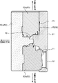
本発明の実施形態に係る鋳造品の製造方法は、図1に示される開口部2(貫通孔)を有する鋳造品1を製造する方法である。開口部2は、本発明の「孔部」に相当する。
The method for producing a cast product according to the embodiment of the present invention is a method for producing a
鋳造品1の製造方法について説明する前に、鋳造品1の構造について説明する。
Before explaining the manufacturing method of the
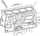
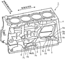
図1に示される例では、鋳造品1は、直列4気筒エンジンのシリンダブロック(以下、「シリンダブロック1」と称する)である。シリンダブロック1は、気筒列方向における一方側の端部(エンジン後側の端部)に、トランスミッションケース(図示略)が固定されるトランスミッション固定壁4を有し、気筒列方向における中央部に、エンジンの補機(図示略)等が固定される取付ボス6を有している。
In the example shown in FIG. 1, the
さらに、シリンダブロック1は、気筒列直交方向における両側の側面3に、当該側面3から気筒列直交方向に突出する固定壁補強用リブ5と、取付ボス補強用リブ7とを有している。固定壁補強用リブ5および取付ボス補強用リブ7は、本発明の「補強壁部」に相当する。
Furthermore, the
図1に示されるように、固定壁補強用リブ5は、中央に開口部2aが形成された板状の部材であって、平面視で直角三角形状に形成されている。開口部2aは、固定壁補強用リブ5を厚み方向(後述の型開きを行う方向と直交する方向)に貫通している。固定壁補強用リブ5は、直角をなすコーナ部5aからトランスミッション固定壁4に沿って気筒列直交方向に延びる第1直線状部5bと、コーナ部5aからシリンダブロック1の側面3に沿って気筒列方向に延びる第2直線状部5cと、第1直線状部5bの反コーナ部側の端部と第2直線状部5cの反コーナ部側端部とを結ぶ第3直線状部5dとを有している。第1直線状部5bは、トランスミッション固定壁4と一体に形成され、第2直線状部5cは、シリンダブロック1の側面3と一体に形成されている。固定壁補強用リブ5は、トランスミッション固定壁4とシリンダブロック1の側面3とを連結し、トランスミッション(図示略)の荷重を受けるトランスミッション固定壁4を補強する。
As shown in FIG. 1, the fixed wall reinforcing rib 5 is a plate-like member having an
なお、第1直線状部5bと、第2直線状部5cと、第3直線状部5dとで囲まれる領域が開口部2aとなっているが、その開口部2aが固定壁補強用リブ5の剛性に与える影響は小さい。このため、開口部2aを有する固定壁補強用リブ5は、十分に補強用リブとしての機能を果たすことができる。しかも、開口部2aを形成することにより、軽量化と材料使用量の削減とを図ることができる。
In addition, although the area | region enclosed by the 1st
図1に示されるように、取付ボス補強用リブ7は中央に開口部2bが形成された板状の部材であって、平面視で長方形状に形成されており、2つの取付ボス6の間に架け渡されている。開口部2bは、取付ボス補強用リブ7を厚み方向(後述の型開きを行う方向と直交する方向)に貫通している。取付ボス補強用リブ7は、シリンダブロック1の側面3に沿って気筒列方向に延びる第1直線状部7aと、一方の取付ボス6に沿って気筒列直交方向に延びる第2直線状部7bと、他方の取付ボス6に沿って設けられる板状部7cと、第2直線状部7bの反シリンダボア側の端部と板状部7cの反シリンダボア側の端部とを結ぶ第3直線状部7dとを有している。第1直線状部7aは、シリンダブロック1の側面3と一体に形成され、第2直線状部7bは、一方の取付ボス6と一体に形成され、板状部7cは、他方の取付ボス6と一体に形成されている。取付ボス補強用リブ7は、2つの取付ボス6とシリンダブロック1の側面3とを連結し、補機等の荷重を受ける2つの取付ボス6を補強する。
As shown in FIG. 1, the mounting
なお、第1直線状部7aと、第2直線状部7bと、板状部7cと、第3直線状部7dとで囲まれる領域が開口部2bとなっているが、その開口部2bが取付ボス補強用リブ7の剛性に与える影響は小さい。このため、開口部2bを有する取付ボス補強用リブ7は、十分に補強用リブとしての機能を果たすことができる。しかも、開口部2bを形成することにより、軽量化と材料使用量の削減とを図ることができる。
In addition, although the area | region enclosed by the 1st
なお、図1には、シリンダブロック1における気筒列方向に沿った2つの側面のうちの一方の側面3のみを示しているが、他方の側面にも、開口部が形成された同様の固定壁補強用リブおよび取付ボス補強用リブが設けられている。
FIG. 1 shows only one side surface 3 of the two side surfaces along the cylinder row direction in the
次に、シリンダブロック1を製造する際に使用される鋳型装置(金型装置)8および中子9について説明する。鋳型装置8は、本発明の「鋳型」に相当する。
Next, the mold apparatus (mold apparatus) 8 and the
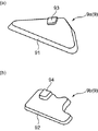
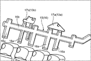
図2,3,9に示されるように、中子9(図2参照)は置き中子であり、固定壁補強用リブ5に開口部2aを形成するために用いられる固定壁用中子9a(図2(a)参照)と、取付ボス補強用リブ7に開口部2bを形成するために用いられる取付ボス用中子9b(図2(b)参照)とを有している。
As shown in FIGS. 2, 3, and 9, the core 9 (see FIG. 2) is a placement core and is used for forming the
固定壁用中子9aは、平板状に形成されるとともに、開口部2aの内周壁の形状に一致する周面形状を有している。固定壁用中子9aの周面91は、固定壁用中子9aを固定壁補強用リブ5から除去するのを容易にするための抜き勾配を有している。固定壁用中子9aの厚みは、固定壁補強用リブ5と同じに設定されている。さらに、固定壁用中子9aは、固定壁補強用リブ5を鋳造するリブ成形領域10a内で固定壁用中子9aを位置決めするための位置決め用凸部93を有している。
The fixed
取付ボス用中子9bは、平板状に形成されるとともに、開口部2bの内周壁の形状に一致する周面形状を有している。取付ボス用中子9bの周面92は、取付ボス用中子9bを取付ボス補強用リブ7から除去するのを容易にするための抜き勾配を有している。取付ボス用中子9bの厚みは、取付ボス補強用リブ7の厚みと同じに設定されている。さらに、取付ボス用中子9bは、取付ボス補強用リブ7を鋳造するリブ成形領域10b内で取付ボス用中子9bを位置決めするための位置決め用凸部94を有している。
The mounting
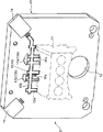
図4,5に示されるように、鋳型装置8は、1つの固定型81と、5つの可動型82とを備えている。
As shown in FIGS. 4 and 5, the mold apparatus 8 includes one fixed
図4〜7に示されるように、固定型81は、輪郭が四角形状をなす板状部材であって、厚み方向が横方向(水平方向)を向くように縦置きに配置される。固定型81は、シリンダブロック1の下面を成形する。固定型81は、溶湯を注入する湯口部12と、シリンダブロック1を鋳造する第1キャビティ10に溶湯を供給する湯道部11と、第1キャビティ10内のガスを排出するガス抜き通路16(図6,7参照)を形成する溝部15とを有している。図4,5に示されるように、ガス抜き通路16は、第1キャビティ10よりも溶湯流れ方向の下流側に設けられる通路であって、当該通路に溶湯が流入する前に第1キャビティ10内のガスを排出することにより、第1キャビティ10に溶湯が流入する際の流入抵抗を低減するものである。
As shown in FIGS. 4 to 7, the fixed
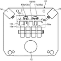
図4〜6に示されるように、ガス抜き通路16は、第1キャビティ10を介して湯口部12とは反対側(上側)に位置しており、これにより、ガス抜き通路16は第1キャビティ10よりも溶湯流れ方向下流側に位置するようになっている。図6〜8に示されるように、ガス抜き通路16は、第1キャビティ10から上方へ直線状に延びる複数(図6〜8に示される例では7つ)の縦方向部16aと、これら縦方向部の各上端部(ガス流れ方向の下流端部)よりやや下側(上流側)の部分と連通し、水平方向(横方向)に直線状に延びる1つの横方向部16bとを有している。
As shown in FIGS. 4 to 6, the
そして、複数の縦方向部16aのうち、2つの縦方向部16aの上側に、固定壁用中子9aを鋳造するキャビティ13aが形成され、キャビティ13aは、上記2つの縦方向部16aの上端部(下流端部)と連通している。さらに、他の2つの縦方向部16aの上側に、取付ボス用中子9bを鋳造するキャビティ13bが形成され、キャビティ13bは、上記他の2つの縦方向部16aの上端部(下流端部)と連通している。
And the
さらに、固定型81は、互いに間隔を隔てて配置される1対のガス抜き弁装置14(図6,7参照)を有している。一対のガス抜き弁装置14のうち、図6,7に示される右側のガス抜き弁装置14は、ガス抜き通路16の下流端部と連通している。
Further, the fixed
なお、図6,7に示される左側のガス抜き弁装置14と連通するガス抜き通路(図示略)を形成する溝部(図示略)が、可動型82bに形成されている。
A groove portion (not shown) that forms a gas vent passage (not shown) communicating with the left gas
さらに、固定型81は、図6〜8に示されるように、中子9を鋳造する第2キャビティ13(キャビティ13a,13b)を形成する2つの凹部17a,17bを有している。凹部17a,17bは、1対のガス抜き弁装置14の間に配置されている。
Further, as shown in FIGS. 6 to 8, the fixed
ガス抜き弁装置14(図6,7参照)には、真空ポンプ(図示略)が接続されている。真空ポンプは、ガス抜き弁装置14が開弁している状態において、第1キャビティ10内のガスを鋳型装置8の外部へ吸い出すようになっている。ガス抜き弁装置14は、ガス抜き通路16に溶湯が流入して、その溶湯がガス抜き弁装置14に到達するまでは開弁して、第1キャビティ10内のガスが通過可能となっているが、溶湯がガス抜き弁装置14に到達すると閉弁し、ガスおよび溶湯の通過を阻止する。
A vacuum pump (not shown) is connected to the gas vent valve device 14 (see FIGS. 6 and 7). The vacuum pump sucks out the gas in the
図4,5に示されるように、可動型82は、固定型81に対して所定の間隔を隔てて対向配置される第1可動型82aと、固定型81と第1可動型82aとの間に配置される4つの可動型(スライド型)とを有する。これら4つの可動型(スライド型)のうち、2つの可動型(第2可動型82bおよび第3可動型82c)のみを図示し、他の2つの可動型(第4可動型および第5可動型)の図示は省略する。
As shown in FIGS. 4 and 5, the
第1可動型82aは、固定型81に対して接近/離間する方向に移動可能となっており、固定型81に最も接近した状態では、第2可動型82b、第3可動型82c、第4可動型および第5可動型と組み合わされた状態となる(図4,5参照)。第1可動型82aは、シリンダブロック1の上面を成形し、第2可動型82b、第3可動型82c、第4可動型および第5可動型は、シリンダブロック1の4つの側面を成形する。
The first
第2可動型82bと第3可動型82cは、互いに接近/離間する方向に移動可能となっており、互いに最も接近した状態では、各々が固定型81と組み合わされた状態となる(図4,5参照)。図9に示されるように、第3可動型82cは、リブ成形領域10a,10bを形成する凹部18a,18bを有している。なお、リブ成形領域は、シリンダブロック1の他の側面にリブを形成する際にも適用可能である。
The second
第4可動型と第5可動型は、互いに接近/離間する方向に移動可能となっており、互いに最も接近した状態では、各々が固定型81と組み合わされた状態となる。
The fourth movable type and the fifth movable type are movable in the direction of approaching / separating from each other, and in the state of being closest to each other, each is combined with the fixed
第1可動型82aの移動方向は、第2可動型82b、第3可動型82c、第4可動型、および第5可動型の各々の移動方向と直交する。さらに、第2可動型82bおよび第3可動型82cの移動方向は、第4可動型および第5可動型の移動方向と直交する。
The moving direction of the first
図4,5に示されるように、1つの固定型81と5つの可動型とを組み合わせることにより、これら6つの型の間に、シリンダブロック1を鋳造する第1キャビティ10が形成されるとともに、型81,82aの間に、固定壁用中子9aおよび取付ボス用中子9bを鋳造する第2キャビティ13(13a,13b)と、上記ガス抜き通路16とが形成される。
As shown in FIGS. 4 and 5, by combining one fixed
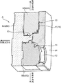
図9に示されるように、第1キャビティ10は、固定壁補強用リブ5を鋳造するリブ成形領域10aと、取付ボス補強用リブ7を鋳造するリブ成形領域10bとを有している。リブ成形領域10a,10bは、本発明の「補強壁部成形領域」に相当する。
As shown in FIG. 9, the
さらに、第1キャビティ10は、固定壁用中子9aの位置決め用凸部93と嵌合可能な位置決め用凹部10cと、取付ボス用中子9bの位置決め用凸部94と嵌合可能な位置決め用凹部10dとを有している。位置決め用凸部93が位置決め用凹部10cに嵌め込まれることにより、固定壁用中子9aが位置決めされ、位置決め用凸部94が位置決め用凹部10dに嵌め込まれることにより、取付ボス用中子9bが位置決めされる。
Further, the
なお、位置決め用凸部93および位置決め用凹部10cは、可動型82を型開きする際に位置決め用凹部10cから位置決め用凸部93を取り出せるような形状に形成されている。同様に、位置決め用凸部94および位置決め用凹部10dは、可動型82を型開きする際に位置決め用凹部10dから位置決め用凸部94を取り出せるような形状に形成されている。
The positioning
次に、鋳型装置8および中子9を用いたシリンダブロック1の製造方法について説明する。
Next, a method for manufacturing the
上記製造方法は、概略的には、図10に示されるように、第1工程と、第2工程と、第2工程の後に繰り返される工程とを含む。すなわち、上記製造工程は、固定壁補強用リブ5および取付ボス補強用リブ7に開口部が形成されていない1番目のシリンダブロック1および中子9(9a,9b)を製造する第1工程と、第1工程で鋳造された1番目の中子9を用いて、固定壁補強用リブ5および取付ボス補強用リブ7に開口部2(2a,2b)が形成された2番目のシリンダブロック1と2番目の中子9(9a,9b)とを製造する第2工程と、n番目(nは2以上の整数、2を初期値とする)に製造された中子9を用いて、固定壁補強用リブ5および取付ボス補強用リブ7に開口部2(2a,2b)が形成された(n+1)番目のシリンダブロック1と(n+1)番目の中子9(9a,9b)とを製造する工程とを含み、nを初期値から順次繰り上げつつ当該工程を繰り返すという方法である。以下、具体的に説明する。
As shown in FIG. 10, the manufacturing method schematically includes a first step, a second step, and a step repeated after the second step. That is, the manufacturing process includes a first process of manufacturing the
まず、固定型81、可動型82a,82b,82cを組み合わせた状態の鋳型装置8を準備する(図4,5参照)。そして、ガス抜き弁装置14が開弁した状態で、真空ポンプを作動させて、第1キャビティ10および第2キャビティ13内の空気を外部へ排出する。つまり、真空ポンプを作動させることにより、ガス抜き通路16を通じて第1キャビティ10および第2キャビティ13内の空気が排出され、これにより、第1キャビティ10および第2キャビティ13内が低圧状態となる。
First, the mold apparatus 8 in a state in which the fixed
次いで、真空ポンプを作動させたまま、湯口部12から湯道部11を通じて第1キャビティ10、ガス抜き通路16、および第2キャビティ13内にアルミニウム合金等の溶湯を注湯する(圧入する)。第1キャビティ10および第2キャビティ13内が低圧状態となっているため、第1キャビティ10および第2キャビティ13内への溶湯の流入が促進される。さらに、第1キャビティ10よりも溶湯流れ方向下流側に、ガス抜き通路16および第2キャビティ13が設けられているため、第1キャビティ10への溶湯の流入抵抗が低減され、溶湯の流入がさらに促進される。
Next, molten metal such as aluminum alloy is poured (press-fitted) into the
溶湯がガス抜き弁装置14に到達すると、ガス抜き弁装置14が閉弁し、ガス抜き弁装置14からのガスおよび溶湯の流出が阻止される。第1キャビティ10および第2キャビティ13内に溶湯が充填され、注湯が終了すると、充填された溶湯は冷却されて凝固(固化)する。第1キャビティ10内での凝固により1番目の鋳造品である第1鋳造品(第1シリンダブロック1)を鋳造するとともに、第2キャビティ13での凝固により1番目の中子である第1中子9(9a,9b)を鋳造する。
When the molten metal reaches the gas
次いで、可動型82aを固定型81から離間する方向に移動させ(型開き)、さらに、可動型82b,82cを互いに離間する方向に移動させる(型開き)とともに、押出機構を作動させることにより、鋳型装置8から第1シリンダブロック1および第1中子9(9a,9b)を取り出す。ここまでの一連の工程が、第1工程である。
Next, the
次いで、第1工程で鋳造された第1中子9aを第1キャビティ10内のリブ成形領域10a内に配置し、第1中子9bをリブ成形領域10b内に配置する。
Next, the
次いで、可動型82b,82cを互いに接近する方向に移動させ(型閉じ)、さらに、可動型82aを固定型81に接近する方向に移動させる(型閉じ)ことにより、固定型81、可動型82a,82b,82cを組み合わせた状態の鋳型装置8を再度準備(図4,5参照)する。そして、ガス抜き弁装置14が開弁した状態で、真空ポンプを作動させて、第1キャビティ10および第2キャビティ13内の空気を外部へ排出する。
Next, the
次いで、真空ポンプを作動させたまま、湯口部12から湯道部11を通じて第1キャビティ10、ガス抜き通路16、および第2キャビティ13内にアルミニウム合金等の溶湯を注湯する(圧入する)。溶湯がガス抜き弁装置14に到達すると、ガス抜き弁装置14が閉弁し、ガス抜き弁装置14からのガスおよび溶湯の流出が阻止される。第1キャビティ10および第2キャビティ13内に溶湯が充填され、注湯が終了すると、充填された溶湯は冷却されて凝固(固化)する。第1キャビティ10内での凝固により2番目の鋳造品である第2鋳造品(第2シリンダブロック1)を鋳造するとともに、第2キャビティ13内での凝固により2番目の中子である第2中子9(9a,9b)を鋳造する。
Next, molten metal such as aluminum alloy is poured (press-fitted) into the
次いで、鋳型装置8から第2シリンダブロック1および第2中子9(9a,9b)を取り出す。そして、第2シリンダブロック1から第1中子9(9a,9b)を除去する。具体的には、例えば、バイブレータ装置を用いて固定壁補強用リブ5に振動を与えることにより、固定壁補強用リブ5から第1中子9aを除去し、取付ボス補強用リブ7に振動を与えることにより、取付ボス補強用リブ7から第1中子9bを除去する。或いは、開口部2aに嵌まり込んだ状態の第1中子9aを開口部2aの貫通方向に押圧することにより、固定壁補強用リブ5から第1中子9aを除去し、開口部2bに嵌まり込んだ状態の第1中子9bを開口部2bの貫通方向に押圧することにより、取付ボス補強用リブ7から第1中子9bを除去する。これにより、開口部2(2a,2b)から第1中子9(9a,9b)が除去されたシリンダブロック1を製造する。第1工程後のここまでの一連の工程が、第2工程である。
Next, the
次いで、n番目(nは2以上の整数であって、2を初期値とする)の中子である第n中子9aを第1キャビティ10内のリブ成形領域10a内に配置し、第n中子9bをリブ成形領域10b内に配置する。
Next, the n-
次いで、可動型82a,82b,82cを型閉じ方向に移動させて、固定型81、可動型82a,82b,82cを組み合わせた状態の鋳型装置8を再度準備する(図4,5参照)。そして、ガス抜き弁装置14が開弁した状態で、真空ポンプを作動させて、第1キャビティ10および第2キャビティ13内の空気を外部へ排出する。
Next, the
次いで、真空ポンプを作動させたまま、湯口部12から湯道部11を通じて第1キャビティ10、ガス抜き通路16、および第2キャビティ13内にアルミニウム合金等の溶湯を注湯する(圧入する)。溶湯がガス抜き弁装置14に到達すると、ガス抜き弁装置14が閉弁し、ガス抜き弁装置14からのガスおよび溶湯の流出が阻止される。第1キャビティ10および第2キャビティ13内に溶湯が充填され、注湯が終了すると、充填された溶湯は冷却されて凝固(固化)する。第1キャビティ10内での凝固により(n+1)番目の鋳造品である第(n+1)鋳造品(第(n+1)シリンダブロック1)を鋳造するとともに、第2キャビティ13内での凝固により(n+1)番目の中子である第(n+1)中子9(9a,9b)を鋳造する。
Next, molten metal such as aluminum alloy is poured (press-fitted) into the
次いで、鋳型装置8から第(n+1)シリンダブロック1および第(n+1)中子9(9a,9b)を取り出す。そして、第2シリンダブロック1から第n中子9(9a,9b)を除去する。これにより、開口部2(2a,2b)から第n中子9(9a,9b)が除去されたシリンダブロック1を製造する。第2工程後のここまでの一連の工程を、nを初期値2から1つずつ繰り上げつつ繰り返す。
Next, the (n + 1)
(本実施形態の作用効果)
本実施形態によれば、シリンダブロック1を鋳型装置8から取り出した後に当該シリンダブロック1から中子9を除去することで、軽量化を目的とする開口部2が形成されるため、開口部2がアンダーカットとなっている場合であっても、崩壊性の中子を用いることなく、開口部2を容易に形成することができる。さらに、鋳造された中子9を用いて開口部2が形成されるため、中子9の強度が高い。従って、鋳型装置8内に溶湯が高速で射出される場合であっても中子9が破損することがなく、シリンダブロック1を適切に製造することができる。しかも、鋳型装置8でシリンダブロック1を鋳造すると同時に、当該鋳型装置8により、次回以降のシリンダブロック1の鋳造で使用される中子9をシリンダブロック1と同一材料で製造することができるため、シリンダブロック1と中子9とを容易かつ効率よく製造することができる。
(Operational effect of this embodiment)
According to the present embodiment, the
また、本実施形態によれば、鋳型装置8でシリンダブロック1を鋳造すると同時に、当該鋳型装置8により、次回のシリンダブロック1の鋳造で使用される中子9をシリンダブロック1と同一材料で製造する工程が繰り返されるため、効率のよい鋳造品および中子の製造を継続することができる。しかも、最新の中子9を用いて開口部2が形成されるため、開口部2を精度よく形成することができる。
Further, according to the present embodiment, the
また、本実施形態によれば、鋳抜きピン或いは鋳抜き型では開口部2を形成することが難しい板状の固定壁補強用リブ5および取付ボス補強用リブ7であっても、その固定壁補強用リブ5および取付ボス補強用リブ7に、鋳造で得られた中子9の除去によって開口部2を容易に形成することができる。さらに、開口部2を形成することにより、固定壁補強用リブ5および取付ボス補強用リブ7を軽量化することができる。
Moreover, according to this embodiment, even if it is the plate-shaped fixed wall reinforcing rib 5 and the mounting
また、本実施形態によれば、第1キャビティ10への溶湯の流入を促進し、第1キャビティ10の隅々まで速やかに溶湯を流入させて、シリンダブロック1の生産効率を高めるとともに、シリンダブロック1の品質を高めることができる。
Further, according to the present embodiment, the inflow of the molten metal into the
また、本実施形態によれば、一対のガス抜き弁装置14の間のスペースに、第2キャビティ13をコンパクトに配置することができる。
Moreover, according to this embodiment, the
なお、上記実施形態では、シリンダブロック1を製造しているが、これに限定されず、シリンダヘッドや、他の種類の鋳造品を製造してもよい。
In addition, in the said embodiment, although the
また、上記実施形態では、固定壁補強用リブ5等に開口部2(貫通孔)を形成しているが、凹部(非貫通孔)を形成してもよい。 Moreover, in the said embodiment, although the opening part 2 (through-hole) is formed in the fixed wall reinforcement rib 5 grade | etc., You may form a recessed part (non-through-hole).
また、上記実施形態では、第1工程において、リブ成形領域10a,10b内に中子を配置していないが、他の鋳型装置で鋳造された中子を第1工程においてリブ成形領域10a,10b内に配置してもよい。この場合には、第1工程により、固定壁補強用リブ5および取付ボス補強用リブ7に開口部が形成されたシリンダブロック1を製造することができる。
Moreover, in the said embodiment, although the core is not arrange | positioned in the rib shaping | molding area |
1 シリンダブロック(鋳造品)
2 開口部(孔部)
5 固定壁補強用リブ(補強壁部)
7 取付ボス補強用リブ(補強壁部)
8 鋳型装置(鋳型)
9 中子
9a 固定壁用中子
9b 取付ボス用中子
10 第1キャビティ
11 湯道部
13 第2キャビティ
14 ガス抜き弁装置
16 ガス抜き通路
1 Cylinder block (cast product)
2 opening (hole)
5 Fixed wall reinforcing rib (reinforcing wall)
7 Mounting boss reinforcing rib (reinforcing wall)
8 Molding device (mold)
DESCRIPTION OF
Claims (4)
前記鋳造品を鋳造する第1キャビティと、前記孔部を形成するための中子を鋳造する第2キャビティとを有する鋳型を用いて、前記第1キャビティにより1番目の鋳造品である第1鋳造品を鋳造するとともに前記第2キャビティにより1番目の中子である第1中子を鋳造し、前記鋳型から前記第1鋳造品および前記第1中子を取り出す第1工程と、
前記第1工程で鋳造された前記第1中子を前記第1キャビティ内の所定箇所に配置した後に、前記第1キャビティにより2番目の鋳造品である第2鋳造品を鋳造するとともに前記第2キャビティにより2番目の中子である第2中子を鋳造し、前記鋳型から前記第2鋳造品および前記第2中子を取り出し、前記第2鋳造品から前記第1中子を除去することにより、孔部を有する鋳造品を製造する第2工程とを含み、
前記鋳造品は、エンジンのシリンダブロックであってその側面に厚み方向に貫通する貫通孔を有する板状の補強用リブが一体に形成されるものであり、
前記鋳型として、前記第1キャビティに前記補強用リブを形成するための補強壁部成形領域が形成された鋳型を用い、
前記第2工程以降の工程では、前記補強壁部成形領域内に、前記第2キャビティにより鋳造された中子を配置することを特徴とする、鋳造品の製造方法。 A method for producing a cast product having a hole,
Using a mold having a first cavity for casting the casting and a second cavity for casting a core for forming the hole, the first casting is the first casting by the first cavity. Casting a product, casting a first core as a first core by the second cavity, and taking out the first cast product and the first core from the mold;
After the first core cast in the first step is disposed at a predetermined location in the first cavity, a second cast product that is a second cast product is cast by the first cavity and the second core is cast. A second core, which is a second core, is cast by the cavity, the second cast product and the second core are taken out from the mold, and the first core is removed from the second cast product. , it looks containing a second step of producing a cast product having a hole,
The cast product is a cylinder block of an engine, and a plate-like reinforcing rib having a through-hole penetrating in a thickness direction on a side surface thereof is integrally formed.
As the mold, a mold in which a reinforcing wall forming region for forming the reinforcing rib is formed in the first cavity is used.
In the steps after the second step, a core cast by the second cavity is arranged in the reinforcing wall portion forming region .
Priority Applications (1)
| Application Number | Priority Date | Filing Date | Title |
|---|---|---|---|
| JP2015221287A JP6350488B2 (en) | 2015-11-11 | 2015-11-11 | Casting manufacturing method |
Applications Claiming Priority (1)
| Application Number | Priority Date | Filing Date | Title |
|---|---|---|---|
| JP2015221287A JP6350488B2 (en) | 2015-11-11 | 2015-11-11 | Casting manufacturing method |
Publications (2)
| Publication Number | Publication Date |
|---|---|
| JP2017087268A JP2017087268A (en) | 2017-05-25 |
| JP6350488B2 true JP6350488B2 (en) | 2018-07-04 |
Family
ID=58769916
Family Applications (1)
| Application Number | Title | Priority Date | Filing Date |
|---|---|---|---|
| JP2015221287A Expired - Fee Related JP6350488B2 (en) | 2015-11-11 | 2015-11-11 | Casting manufacturing method |
Country Status (1)
| Country | Link |
|---|---|
| JP (1) | JP6350488B2 (en) |
Family Cites Families (6)
| Publication number | Priority date | Publication date | Assignee | Title |
|---|---|---|---|---|
| JPS6362246U (en) * | 1986-10-06 | 1988-04-25 | ||
| JPH02142662A (en) * | 1988-11-24 | 1990-05-31 | Sky Alum Co Ltd | Method for casting metal using core and metallic hollow core |
| JPH0475748A (en) * | 1990-07-13 | 1992-03-10 | Japan Casting & Forging Corp | Casting mold for cylindrical casting and casting method thereof |
| JPH04153549A (en) * | 1990-10-15 | 1992-05-27 | Mazda Motor Corp | Cylinder block and manufacture thereof |
| JP3180233B2 (en) * | 1992-07-23 | 2001-06-25 | 根本 賢 | Cast products cast using a special core |
| JP2001205642A (en) * | 2000-01-25 | 2001-07-31 | Ngk Insulators Ltd | Method and mold for molding metal core |
-
2015
- 2015-11-11 JP JP2015221287A patent/JP6350488B2/en not_active Expired - Fee Related
Also Published As
| Publication number | Publication date |
|---|---|
| JP2017087268A (en) | 2017-05-25 |
Similar Documents
| Publication | Publication Date | Title |
|---|---|---|
| JP5026806B2 (en) | Die casting mold | |
| CN103447468A (en) | Single-mold multi-cavity gravity casting wheel hub mould and method for casting wheel hub | |
| JP5319945B2 (en) | Model having disappearance model in part and casting method using the same | |
| JP5663800B1 (en) | Runway and casting method capable of rapid solidification | |
| JP6350488B2 (en) | Casting manufacturing method | |
| JP2006212697A (en) | Die for die casting | |
| CN103286296A (en) | Damper inner core die-casting die | |
| JP6324133B2 (en) | Aluminum die-casting method and die-casting products | |
| JP2009022957A (en) | Method for producing casting mold | |
| JP4273963B2 (en) | Die casting mold and die casting method | |
| CN203170943U (en) | Die-casting die of cantilever support of automobile engine | |
| AU2017249418B2 (en) | System and method for manufacturing railcar coupler headcores | |
| JP2009269050A (en) | Die-casting die | |
| CN220659140U (en) | Casting structure of dynamic balance block casting of high-speed punch | |
| US20080105398A1 (en) | Article For Multiple Core Stacking And Method Thereof | |
| CN218963954U (en) | Sand casting die for automobile parts | |
| JP5726985B2 (en) | Mold for casting | |
| JPH09168855A (en) | Method an device for production of die for resin forming | |
| CN215467889U (en) | Casting template of gear box casting | |
| KR20130102818A (en) | Molding | |
| CN108246979B (en) | Casting method of shaft casting | |
| JP5026247B2 (en) | Molding method, filter for molding material and die with filter | |
| JP5578122B2 (en) | Casting apparatus and casting method | |
| CN104249141B (en) | Molded component and manufacturing method of molded component | |
| JP2005081380A (en) | Casting method and casting |
Legal Events
| Date | Code | Title | Description |
|---|---|---|---|
| A621 | Written request for application examination |
Free format text: JAPANESE INTERMEDIATE CODE: A621 Effective date: 20170323 |
|
| A977 | Report on retrieval |
Free format text: JAPANESE INTERMEDIATE CODE: A971007 Effective date: 20180208 |
|
| A131 | Notification of reasons for refusal |
Free format text: JAPANESE INTERMEDIATE CODE: A131 Effective date: 20180227 |
|
| A521 | Request for written amendment filed |
Free format text: JAPANESE INTERMEDIATE CODE: A523 Effective date: 20180420 |
|
| TRDD | Decision of grant or rejection written | ||
| A01 | Written decision to grant a patent or to grant a registration (utility model) |
Free format text: JAPANESE INTERMEDIATE CODE: A01 Effective date: 20180508 |
|
| A61 | First payment of annual fees (during grant procedure) |
Free format text: JAPANESE INTERMEDIATE CODE: A61 Effective date: 20180521 |
|
| R150 | Certificate of patent or registration of utility model |
Ref document number: 6350488 Country of ref document: JP Free format text: JAPANESE INTERMEDIATE CODE: R150 |
|
| LAPS | Cancellation because of no payment of annual fees |