JP6348985B2 - Apparatus for heating smoking material and article for smoking material - Google Patents
Apparatus for heating smoking material and article for smoking material Download PDFInfo
- Publication number
- JP6348985B2 JP6348985B2 JP2016558049A JP2016558049A JP6348985B2 JP 6348985 B2 JP6348985 B2 JP 6348985B2 JP 2016558049 A JP2016558049 A JP 2016558049A JP 2016558049 A JP2016558049 A JP 2016558049A JP 6348985 B2 JP6348985 B2 JP 6348985B2
- Authority
- JP
- Japan
- Prior art keywords
- smoking article
- smoking
- housing
- article
- electrodes
- Prior art date
- Legal status (The legal status is an assumption and is not a legal conclusion. Google has not performed a legal analysis and makes no representation as to the accuracy of the status listed.)
- Active
Links
Images


Classifications
-
- A—HUMAN NECESSITIES
- A24—TOBACCO; CIGARS; CIGARETTES; SIMULATED SMOKING DEVICES; SMOKERS' REQUISITES
- A24F—SMOKERS' REQUISITES; MATCH BOXES; SIMULATED SMOKING DEVICES
- A24F40/00—Electrically operated smoking devices; Component parts thereof; Manufacture thereof; Maintenance or testing thereof; Charging means specially adapted therefor
- A24F40/50—Control or monitoring
-
- A—HUMAN NECESSITIES
- A24—TOBACCO; CIGARS; CIGARETTES; SIMULATED SMOKING DEVICES; SMOKERS' REQUISITES
- A24F—SMOKERS' REQUISITES; MATCH BOXES; SIMULATED SMOKING DEVICES
- A24F40/00—Electrically operated smoking devices; Component parts thereof; Manufacture thereof; Maintenance or testing thereof; Charging means specially adapted therefor
- A24F40/40—Constructional details, e.g. connection of cartridges and battery parts
- A24F40/46—Shape or structure of electric heating means
-
- A—HUMAN NECESSITIES
- A24—TOBACCO; CIGARS; CIGARETTES; SIMULATED SMOKING DEVICES; SMOKERS' REQUISITES
- A24B—MANUFACTURE OR PREPARATION OF TOBACCO FOR SMOKING OR CHEWING; TOBACCO; SNUFF
- A24B15/00—Chemical features or treatment of tobacco; Tobacco substitutes, e.g. in liquid form
- A24B15/10—Chemical features of tobacco products or tobacco substitutes
- A24B15/16—Chemical features of tobacco products or tobacco substitutes of tobacco substitutes
- A24B15/167—Chemical features of tobacco products or tobacco substitutes of tobacco substitutes in liquid or vaporisable form, e.g. liquid compositions for electronic cigarettes
-
- A—HUMAN NECESSITIES
- A24—TOBACCO; CIGARS; CIGARETTES; SIMULATED SMOKING DEVICES; SMOKERS' REQUISITES
- A24F—SMOKERS' REQUISITES; MATCH BOXES; SIMULATED SMOKING DEVICES
- A24F40/00—Electrically operated smoking devices; Component parts thereof; Manufacture thereof; Maintenance or testing thereof; Charging means specially adapted therefor
- A24F40/20—Devices using solid inhalable precursors
-
- A—HUMAN NECESSITIES
- A24—TOBACCO; CIGARS; CIGARETTES; SIMULATED SMOKING DEVICES; SMOKERS' REQUISITES
- A24F—SMOKERS' REQUISITES; MATCH BOXES; SIMULATED SMOKING DEVICES
- A24F40/00—Electrically operated smoking devices; Component parts thereof; Manufacture thereof; Maintenance or testing thereof; Charging means specially adapted therefor
- A24F40/50—Control or monitoring
- A24F40/51—Arrangement of sensors
-
- A—HUMAN NECESSITIES
- A24—TOBACCO; CIGARS; CIGARETTES; SIMULATED SMOKING DEVICES; SMOKERS' REQUISITES
- A24F—SMOKERS' REQUISITES; MATCH BOXES; SIMULATED SMOKING DEVICES
- A24F40/00—Electrically operated smoking devices; Component parts thereof; Manufacture thereof; Maintenance or testing thereof; Charging means specially adapted therefor
- A24F40/50—Control or monitoring
- A24F40/53—Monitoring, e.g. fault detection
-
- A—HUMAN NECESSITIES
- A24—TOBACCO; CIGARS; CIGARETTES; SIMULATED SMOKING DEVICES; SMOKERS' REQUISITES
- A24F—SMOKERS' REQUISITES; MATCH BOXES; SIMULATED SMOKING DEVICES
- A24F47/00—Smokers' requisites not otherwise provided for
-
- A—HUMAN NECESSITIES
- A61—MEDICAL OR VETERINARY SCIENCE; HYGIENE
- A61M—DEVICES FOR INTRODUCING MEDIA INTO, OR ONTO, THE BODY; DEVICES FOR TRANSDUCING BODY MEDIA OR FOR TAKING MEDIA FROM THE BODY; DEVICES FOR PRODUCING OR ENDING SLEEP OR STUPOR
- A61M15/00—Inhalators
- A61M15/06—Inhaling appliances shaped like cigars, cigarettes or pipes
-
- G—PHYSICS
- G01—MEASURING; TESTING
- G01D—MEASURING NOT SPECIALLY ADAPTED FOR A SPECIFIC VARIABLE; ARRANGEMENTS FOR MEASURING TWO OR MORE VARIABLES NOT COVERED IN A SINGLE OTHER SUBCLASS; TARIFF METERING APPARATUS; MEASURING OR TESTING NOT OTHERWISE PROVIDED FOR
- G01D5/00—Mechanical means for transferring the output of a sensing member; Means for converting the output of a sensing member to another variable where the form or nature of the sensing member does not constrain the means for converting; Transducers not specially adapted for a specific variable
- G01D5/12—Mechanical means for transferring the output of a sensing member; Means for converting the output of a sensing member to another variable where the form or nature of the sensing member does not constrain the means for converting; Transducers not specially adapted for a specific variable using electric or magnetic means
- G01D5/14—Mechanical means for transferring the output of a sensing member; Means for converting the output of a sensing member to another variable where the form or nature of the sensing member does not constrain the means for converting; Transducers not specially adapted for a specific variable using electric or magnetic means influencing the magnitude of a current or voltage
- G01D5/24—Mechanical means for transferring the output of a sensing member; Means for converting the output of a sensing member to another variable where the form or nature of the sensing member does not constrain the means for converting; Transducers not specially adapted for a specific variable using electric or magnetic means influencing the magnitude of a current or voltage by varying capacitance
Description
関連出願の相互参照
本出願は2014年3月21日に出願された米国仮出願第61/968,780号の利益を主張する。また当該出願の全文は参照により本明細書に組み込まれる。
This application claims the benefit of US Provisional Application No. 61 / 968,780, filed March 21, 2014. The entire text of the application is incorporated herein by reference.
本発明は、喫煙材を加熱するために用意された装置と、喫煙材からなる物品とに関する。 The present invention relates to an apparatus prepared for heating a smoking material and an article made of the smoking material.
紙巻きタバコ、シガーなどの喫煙品は使用の間、タバコを燃焼させてタバコ煙を発生させる。燃焼を伴わず化合物を放出する製品を創出することによって、タバコを燃焼させるこれら物品に対する代用品を提供しようとする試みが行われている。そのような製品の具体例としては、材料を燃焼するのではなく加熱することで化合物を放出するいわゆる発熱するが燃焼しない(heat−not−burn)製品がある。その材料としては具体的にはタバコまたは他の非タバコ製品がある。これはニコチンを含んでも、含まなくてもよい。 Smoking articles, such as cigarettes and cigars, burn tobacco and generate tobacco smoke during use. Attempts have been made to provide alternatives to these articles that burn tobacco by creating products that release compounds without burning. A specific example of such a product is a so-called exothermic but non-burning product that releases a compound by heating rather than burning the material. The material specifically includes tobacco or other non-tobacco products. This may or may not include nicotine.
本発明の第1の態様によると、喫煙可能材料の加熱を可能とし、喫煙可能材料の少なくとも1つの成分を揮発させる装置であって、
ハウジングと
使用時に喫煙材物品をハウジングへ導入した際の静電容量の変化を検知し、喫煙材物品の識別を可能にするよう配置された容量センサーと
を含む装置が提供される。
According to a first aspect of the present invention, an apparatus that enables heating of a smokable material and volatilizes at least one component of the smokable material comprising:
An apparatus is provided that includes a housing and a capacitive sensor arranged to sense a change in capacitance upon introduction of the smoking article into the housing during use and to allow identification of the smoking article .
代表的な実施態様では、容量センサーは電極を含み、装置は使用時にハウジングに導入された喫煙材物品および電極の静電容量の変化を検知するよう構成、配置されたプロセッサーを含む。 In an exemplary embodiment, the capacitive sensor includes an electrode, and the apparatus includes a smoking article introduced into the housing in use and a processor configured and arranged to detect changes in the capacitance of the electrode.
代表的な実施態様では、容量センサーは少なくとも2つの電極を含み、装置は使用時に喫煙材物品がハウジングに導入された時に少なくとも2つの電極の静電容量の変化を検知するよう構成、配置されたプロセッサーを含む。代表的な実施態様では、少なくとも2つの電極は使用時にハウジングに導入された喫煙材物品の少なくとも一部が少なくとも2つの電極の間に位置できるように配置される。 In an exemplary embodiment, the capacitive sensor includes at least two electrodes, and the device is configured and arranged to sense a change in capacitance of the at least two electrodes when the smoking article is introduced into the housing in use. Includes processor. In an exemplary embodiment, the at least two electrodes are positioned such that at least a portion of the smokable article introduced into the housing in use can be located between the at least two electrodes.
代表的な実施態様では、装置は静電容量の変化が少なくとも1つの所定の基準を満たす場合に使用時にハウジングに導入された喫煙材物品を加熱するためだけに作動させるように構成、配置された回路を含む。 In an exemplary embodiment, the device is constructed and arranged to operate only to heat the smoking article introduced into the housing in use if the change in capacitance meets at least one predetermined criterion. Includes circuitry.
代表的な実施態様では、装置は容量センサーへ充電電圧をかけて容量センサーが相対的に高い電圧になる充電と容量センサーが相対的に低い電圧になる放電とを繰り返しできるよう構成、配置された回路を含み、回路は所定時間における容量センサー上の相対的に高い電圧と相対的に低い電圧の間での遷移の回数が所定数未満である場合に使用時にハウジングに導入された喫煙材物品を加熱するためだけに装置を作動させるように配置されている。代表的な実施態様では、先の所定数とはハウジングに導入された喫煙材物品が存在しない時の所定時間における容量センサー上の相対的に高い電圧と相対的に低い電圧の間での遷移の回数である。 In an exemplary embodiment, the device is configured and arranged to repeat charging with a charging voltage applied to the capacitive sensor so that the capacitive sensor is at a relatively high voltage and discharging at which the capacitive sensor is at a relatively low voltage. A circuit that includes a smoking material article introduced into the housing in use when the number of transitions between a relatively high voltage and a relatively low voltage on the capacitive sensor at a given time is less than a given number. It is arranged to operate the device only for heating. In an exemplary embodiment, the predetermined number is a transition between a relatively high voltage and a relatively low voltage on the capacitive sensor at a predetermined time when there is no smoking article introduced into the housing. Is the number of times.
代表的な実施態様では、装置は使用において喫煙材物品がハウジングに導入された際の電気抵抗の指標を供するように配置された抵抗センサーを含む。 In an exemplary embodiment, the apparatus includes a resistance sensor arranged to provide an indication of electrical resistance when the smoking article is introduced into the housing in use.
代表的な実施態様では、装置は使用時にハウジング内に収容されている喫煙材物品を加熱するよう作動可能なヒーターを含む。 In an exemplary embodiment, the apparatus includes a heater operable to heat the smoking article contained within the housing in use.
本発明の第2の態様では喫煙材を加熱して喫煙材の少なくとも1つの成分を揮発させることができる装置であって、
ハウジングと
使用において喫煙材物品がハウジングに導入された際の電気抵抗の指標を供し、喫煙材物品の識別を可能にするよう配列された抵抗センサーとを含む装置が提供される。
The second aspect of the present invention is an apparatus that can heat a smoking material to volatilize at least one component of the smoking material,
Subjecting the indication of the electrical resistance when smoking material article has been introduced into the housing in use a housing, an apparatus including a resistive sensor that is arranged to enable identification of the smoking material article is provided.
代表的な実施態様では、抵抗センサーは少なくとも2つの電極を含み、装置は少なくとも2つの電極を用いて、使用において喫煙材物品がハウジングに導入された際の電気抵抗の指標を供するように構成、配置されたプロセッサーを含んでいる。代表的な実施態様では、少なくとも2つの電極は使用時にハウジングに導入された喫煙材物品の少なくとも一部が少なくとも2つの電極の間に位置してこれらと接触できるように配置され、これら少なくとも2つの電極は使用時に前記した喫煙材物品の少なくとも一部の電気抵抗の指標を供する。 In an exemplary embodiment, the resistance sensor includes at least two electrodes, and the device is configured to use the at least two electrodes to provide an indication of electrical resistance when the smoking article is introduced into the housing in use. Includes deployed processors. In an exemplary embodiment, the at least two electrodes are positioned such that at least a portion of the smoking article introduced into the housing in use is positioned between and in contact with the at least two electrodes, and the at least two The electrode provides an indication of the electrical resistance of at least a portion of the smoking article as described above.
代表的な実施態様では、装置は電気抵抗が少なくとも1つの所定の基準を満たす場合に使用時にハウジングに導入された喫煙材物品を加熱するためだけに装置を作動させるように構成、配置された回路を含む。 In an exemplary embodiment, the device is configured and arranged to operate the device only to heat the smoking article introduced into the housing in use when the electrical resistance meets at least one predetermined criterion. including.
代表的な実施態様では、装置は使用時にハウジング内に収容されている喫煙材物品を加熱するよう作動可能なヒーターを含む。 In an exemplary embodiment, the apparatus includes a heater operable to heat the smoking article contained within the housing in use.
本発明の第3の態様では喫煙材を加熱して喫煙材の少なくとも1つの成分を揮発させることができる装置であって、
ハウジングと
少なくとも2つの異なる検知技術を利用して、使用においてハウジングと関連付けられる時の喫煙材物品を識別するよう構成、配置されたセンサー構造と
を含む装置が提供される。
In a third aspect of the present invention, the apparatus is capable of heating the smoking material to volatilize at least one component of the smoking material,
An apparatus is provided that includes a housing and a sensor structure configured and arranged to identify a smoking article as associated with the housing in use utilizing at least two different sensing techniques.
代表的な実施態様では、少なくとも2つの異なる検知技術の内の1つは容量検知を使用し、少なくとも2つの異なる検知技術のうちのもう一方は抵抗検知を使用する。 In an exemplary embodiment, one of the at least two different sensing technologies uses capacitive sensing and the other of the at least two different sensing technologies uses resistance sensing.
代表的な実施態様では、少なくとも2つの異なる検知技術の内の1つは電気的検知を使用し、少なくとも2つの異なる検知技術のうちのもう一方は光学的検知を使用する。好適な光学的検知技術としては、例えば、1以上のLED(発光ダイオード)、レーザーなどの何らかの光学エミッタ−と対応する1つ以上検出装置とを用いてバーコード(従来の直線タイプでも、近年の2次元的タイプでもよい)を使用して、検出することが挙げられる。使用時の喫煙材上の印またはマーカーの性質などに応じて、可視光、非可視光のいずれも使用できる。 In an exemplary embodiment, one of the at least two different detection techniques uses electrical detection and the other of the at least two different detection techniques uses optical detection. Suitable optical detection techniques include, for example, one or more LEDs (light emitting diodes), bar code (conventional linear types, even in recent years, using some optical emitter such as a laser and corresponding one or more detection devices. Detection may be used. Either visible light or invisible light can be used depending on the nature of the mark or marker on the smoking material during use.
代表的な実施態様では装置は、使用時にハウジング内に収容されている喫煙材物品を加熱するように作動可能なヒーターを含む。 In an exemplary embodiment, the apparatus includes a heater operable to heat the smoking article contained within the housing in use.
本発明の第4の態様では喫煙材物品が提供され、喫煙材の加熱が生じるように配置された装置のセンサーによって検出されるための非金属導電性領域を有する。 In a fourth aspect of the present invention, a smoking article is provided having a non-metallic conductive region for detection by a sensor of the device arranged to cause heating of the smoking article.
代表的な実施態様では、非金属導電性領域は、喫煙材物品を少なくとも部分的に囲む材料をバンド状にしたものである。 In an exemplary embodiment, the non-metallic conductive region is a band of material that at least partially surrounds the smoking article.
代表的な実施態様では、非金属導電性領域は炭素を含む。 In an exemplary embodiment, the non-metallic conductive region includes carbon.
代表的な実施態様では、非金属導電性領域は印刷インク(printed ink)である。 In an exemplary embodiment, the non-metallic conductive region is a printed ink.
一部の例示的実施態様では、喫煙材物品がハウジング内(少なくともその一部)に収容されている場合がある。このような例示的実施態様では、使用時にハウジング内に収容されている喫煙材物品を加熱するよう作動可能なヒーターを装置自体が含んでもよい。別の一部の例示的実施態様では、喫煙材物品がヒーターと一緒に液状または他の形態の喫煙材を含んでもよい。このような例示実施態様では、不可欠なヒーターを備えた喫煙材物品は使用時に装置に接続される場合があり、このとき装置がヒーターの動力源を含んでいるのが一般的である。 In some exemplary embodiments, the smoking article may be contained within (at least a portion of) the housing. In such exemplary embodiments, the device itself may include a heater operable to heat the smoking article contained within the housing in use. In another exemplary embodiment, the smoking article may include a liquid or other form of smoking material together with a heater. In such exemplary embodiments, a smoking article with an indispensable heater may be connected to the device in use, where the device typically includes a power source for the heater.
本発明の実施態様を添付図面を参照し、あくまで例示を目的として説明する。 Embodiments of the present invention will now be described by way of example only with reference to the accompanying drawings.
本明細書で使用する「喫煙材」なる用語には、加熱されることで典型的にエアロゾルの形態の揮発成分を供給する材料が含まれる。「喫煙材」には、いずれのタバコ含有材料が含まれる。タバコ、タバコ派生物、膨張タバコ、再生タバコ、またはタバコ代替え品の内の1つ以上を含んでもよい。また「喫煙材」にはニコチンを含有するか否かに拘わらず他の非タバコ製品を含む場合がある。 As used herein, the term “smoking material” includes materials that are heated to provide a volatile component, typically in the form of an aerosol. “Smoking material” includes any tobacco-containing material. It may include one or more of tobacco, tobacco derivatives, expanded tobacco, regenerated tobacco, or tobacco substitutes. The “smoking material” may include other non-tobacco products regardless of whether or not nicotine is contained.
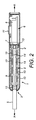
図1を参照すると、喫煙材の少なくとも1つの成分を揮発させ、典型的には吸入可能なエアロゾルを形成するため喫煙材を加熱するよう構成された装置1の一例の斜視図を示している。この装置1はいわゆる「ヒートノットバーン(heat−not−burn)」装置1である。この例における装置1は概ね長尺形状であり、円形断面の概ね長尺の円筒形の外方ハウジング2を備えている。外方ハウジング2は開口端3を有し、これは場合によっては吸い口端とも呼ばれる。外方ハウジング2は断熱材料から形成してもよい。特に好ましい材料はポリエチルエチルケトン(PEEK)であるが、アクリロニトリルブタジエンスチレン(ABS)などの他のプラスチックや他の断熱材料も使用可能である。外方ハウジング2の最も外側の表面は、金属光沢仕上げ(metallic finish)などの装飾コーティングを含んでもよい。外方ハウジング2の最も内側の表面は、熱伝導性の高い材料によって一部または全部をコーティングしてもよい。一例として、この目的のため銅などの金属コーティングが使用される。
Referring to FIG. 1, a perspective view of an example of a
図2は喫煙材加熱用装置1の一例の断面図である。装置1は加熱および揮発させる対象である喫煙材を使用時に収容する加熱チェンバー4を有する。喫煙材は、喫煙材から形成されるまたは喫煙材を含む物品5の形状であってもよく、これはユーザーによって取り外し可能な状態で挿入することが可能である。喫煙材物品5は概ね細長い円筒状であり、例えばカートリッジ、カセットまたはロッドであってもよい。喫煙材物品5は使用時にハウジング2へ挿入される。通常はフィルターなどに接続するため、喫煙材物品5の一端はハウジング2の開口端3を通じて装置1の外へ突出し、フィルターは別個のアイテムであってもよいし、喫煙材物品5が設けられてもよく、フィルターを介してユーザーは使用時に吸入を行う。
FIG. 2 is a cross-sectional view of an example of the smoking
装置1はさらに電子/電力チェンバー6を有する。この例においては、電子/電力チェンバー6は電子制御回路7および電力源8を含んでいる。この例においては、加熱用チェンバー4と電子/電力チェンバー6とは装置1の長手方向軸X−Xに沿って互いに隣接している。図示するこの例では、電子/電力チェンバー6は吸い口端3と離れているが、異なる配置も可能である。以下に説明するように電子制御回路7は喫煙材の加熱を制御し喫煙材物品5を認識または識別するように構成、配置されたマイクロプロセッサー構造などの制御装置を含んでもよい。電子制御回路7は使用時に例えばユーザーによる喫煙材物品5の吸引開始時に起こる圧力変化または空気流速変化に反応するパフ作動センサーなどからの信号などを受け取ってもよい。そして電子制御回路7は、必要な時に「オンデマンド」で喫煙材物品5を加熱を行うために作動することができる。パフ駆動センサーとしては様々な構成が利用可能である。例えば、センサーを基盤とするサーミスター、電子機械デバイス、機械デバイス、光学デバイス、光学機械デバイスおよび微小電子機械デバイス(MEMS)が挙げられる。あるいは装置は、パフを開始するためにユーザーが手動で操作可能なスイッチを備えてもよい。
The
電力源8は電池でもよい。これは再充電可能なものでも再充電不可能なものでもよい。好ましい電池の例としては、例えば、リチウムイオン電池、ニッケル電池(ニッケル−カドミウム電池など)、アルカリ電池等が挙げられる。特に好ましいタイプの電池はLiFePO4電池である。電力源8は加熱用チェンバー4の1以上の加熱エレメント(後述する)に電気的に連結し、(前記したように喫煙材を燃焼させることなく喫煙材を揮発させるため)喫煙材を加熱するための電子制御回路7の制御下において必要な時に電力を供給する。この例では、電池8は電子制御回路7のプリント回路基板の内部に含まれる。別の例では、電池8および電子制御回路7は異なる配置にしてもよい。例えば、電池8および電子制御回路7が装置1の長軸X−Xに沿って互いに隣接するよう配置してもよい。
The power source 8 may be a battery. This may be rechargeable or non-rechargeable. Examples of preferable batteries include lithium ion batteries, nickel batteries (such as nickel-cadmium batteries), and alkaline batteries. A particularly preferred type of battery is a LiFePO4 battery. The power source 8 is electrically connected to one or more heating elements (discussed below) of the
加熱用チェンバー4はヒーター支持スリーブ9の内部に含まれる。スリーブ9はハウジング2の内部に含まれる。この例では、ヒーター支持スリーブ9は円形断面を有する概ね長尺の円筒状である。1つの例ではヒーター支持スリーブ9は、端部では互いに接合し、僅かな距離dを置いて離れている外側の円筒壁および内側の円筒壁を備える2重壁スリーブまたは「真空」スリーブである。あくまで一例として、大きさに関する考えを記載すると、ヒーター支持スリーブ9は長さが約50mm、外径が約9mmであり、距離dは約0.1mm〜約0.12mmである。ある例においてヒーター支持スリーブ9の機能の1つは、外方ハウジング2が熱くならないように、少なくとも使用時に触ることが不可能な程度に熱くならないように加熱用チェンバー4からの外方ハウジング2の断熱を補助することである。ヒーター支持スリーブ9の外側および内側の円筒壁の間の空間には空気が含まれてもよい。しかし、ヒーター支持スリーブ9の断熱性を向上させるため、ヒーター支持スリーブ9の外側および内側の円筒壁の間の空間は脱気されていることが好ましい。あるいは、ヒーター支持スリーブ9の外側および内側の円筒壁の間の空間には、例えば発泡材料などの何らかの他の断熱材を充填してもよい。ヒーター支持スリーブ9の材料は、その内部にある要素に構造安定性を供与する程度にヒーター支持スリーブ9が硬くなるようなものが好ましい。そのような好ましい材料の一例としては例えばステンレスが挙げられる。その他の好ましい材料としては例えば、ポリエチルエチルケトン(PEEK)、セラミックス、ガラス、鉄、アルミニウムなどが挙げられる。
The
装置1の一例として、ヒーター支持スリーブ9は少なくとも1つの加熱エレメント10を含み、場合によっては複数の加熱エレメントまたはヒーターセグメント10を含んでもよい。少なくとも2つのヒーターセグメント10があることが好ましいが、これ以外の数のヒーターセグメント10による構成も可能である。特に図示するこの例では、4つのヒーターセグメント10がある。この例では、ヒーターセグメント10はヒーター支持スリーブ9の長軸X−Xに沿って、またはこれに平行に一列に並んでいる。必要に応じて、例えば順番に(経時的に)または共同で(同時に)喫煙材物品5の選択区域を独立して加熱できるようにするため、少なくとも2つ以上、好ましくは全てのヒーターセグメント10が互いに独立して電力供給されるように、電子制御回路7およびヒーターセグメント10に対する電力接続が構成されることが好ましい。特にこの例では、ヒーターセグメント10は概ね環状または円筒形であり、使用時に喫煙材物品5を含む中空構造である。ある例では、ヒーターセグメント10はセラミック材料から形成される。アルミナ、窒化アルミニウムおよび窒化ケイ素のセラミックスなどが挙げられ、これらはラミネート加工または焼結加工されてもよい。外方ハウジング2から突出し、ユーザーが操作可能なオン/オフスイッチ11を装置1は有している。
As an example of the
ヒーターセグメント10について異なる形状および異なる構成が使用可能である。加えて異なる加熱構成も可能であり、例えば、赤外線を照射して加熱する赤外線ヒーターセグメント10またはヒーターセグメント10の周囲に設けられる抵抗性電気巻線などから形成される抵抗性加熱エレメントが挙げられる。さらに別の加熱構成も使用可能である。
Different shapes and different configurations for the
ユーザーにより装置1へ導入されている特定の喫煙材物品5を識別または認識できることが装置にとって好ましい場合がある。例えば、実際上、全体として特に加熱構造と電子制御回路7が供給する加熱制御とを含む装置1は、喫煙材物品5のある特定の構成(例えばサイズ、形状、特定の喫煙材などの内の1つまたはそれ以上)に対して最適化されることになり、(極めて)異なる特性を備える喫煙材または喫煙材物品5と使用されることは装置1にとって望ましくない。加えて、装置1に導入されている特定の喫煙材物品5または少なくとも一般的な種類の喫煙材物品5を装置1がもし識別または認識できるのであれば、模造品または他の非真正の喫煙材物品5が装置1に使用されるのを排除、少なくとも減少させることができる。装置1が認識する喫煙材物品5のみを加熱するように、また装置1が認識しない喫煙材物品5には作動しないように装置1を構成してもよい。喫煙材物品5が認識されていないことをユーザーに表示するように装置1を構成してもよい。この表示は視覚的(例えばフラッシュまたは一定時間連続的に光る照明などの警告灯)および/または聴覚的(例えば「ビー」という警告音)でもよい。これとは別にまたはこれに加えて、装置1が第1のタイプの喫煙材物品5を認識したら第1の加熱パターンに装置1が従い、装置1が第2のタイプの喫煙材物品5を認識したら第2の異なる加熱パターンに装置1が従うように(そして任意に、さらに別のタイプの喫煙材物品5用にさらなる加熱パターンを提供できるように)装置1を構成してもよい。喫煙材に対する熱伝達速度、種々の加熱サイクルのタイミング、喫煙材のどの部分を最初に加熱するか等々、多くの点において加熱パターンは異なっていてよい。こうすることで、ユーザーに求められる装置に対する作業を最小限にしつつ、異なる基本型の喫煙材物品5で同一の装置1を使用することが可能となる。
It may be preferred for the device that the user can identify or recognize a particular smoking material article 5 introduced into the
ある実施態様のある例では、使用時に喫煙材物品5がハウジング2内に収容されている際の静電容量の変化を検知する容量検知を使用するように装置1は構成、配置されている。ある実施態様の別の例では、ハウジング2内に収容されている喫煙材物品5を検知する抵抗検知を使用するように装置1は構成、配置されている。ある実施態様のまた別の例では、ハウジング2内に収容されている喫煙材物品5を検知する容量検知および抵抗検知を組み合わせて使用するように装置1は構成、配置されている。ある実施態様のある例では、喫煙材物品5がハウジング2内に収容されている時の静電容量の変化を装置1が検知する。喫煙材物品5がハウジング2内に収容されている時の静電容量と喫煙材物品5がハウジング2内に存在しない時の静電容量を実質的に比較する。これらの例のいずれであっても、ハウジング内に収容されているある特定の喫煙材物品5の識別または認識が可能である。ある実施態様のある例では、本明細書で説明するように、装置1のセンサーによって検知されることが可能となる喫煙材物品5が提供される。ある実施態様のある特定の例では、喫煙材物品5には、本明細書で説明するように、装置1のセンサーによって検知され得るストリップ、バンド、その他のマーカーまたは1つ以上の印が設けられている。
In one example of an embodiment, the
一般に本明細書で使用する容量検知は、喫煙材物品5が装置1内部に位置する時の静電容量変化を効果的に検知することで作動する。実質的にある実施態様では、静電容量の指標が得られる。もし静電容量が1つ以上の基準を満たす場合、喫煙材物品5は装置1で使用するのに適していると決定してよく、装置1は喫煙材を加熱するべく通常通り作動し続けることができる。逆にもし静電容量が1以上の基準を満たさない場合、喫煙材物品5は装置1で使用するのに適していないと決定してよく、そして装置1は喫煙材を加熱するべく機能はせず、および/または何らかの警告メッセージをユーザーに発してもよい。
In general, capacity detection as used herein operates by effectively detecting changes in capacitance when the smoking article 5 is located within the
一般に本明細書で使用する静電検知は2つの方法のうち一方で機能すればよい。まず装置1には、実質的にコンデンサからなる1つの「プレート」を供する(少なくとも)1つの電極が設けられ、コンデンサの他の「プレート」は喫煙材物品5(または喫煙材物品5の少なくとも一部の特徴、例えば上述し、以下詳述するマーカーまたは印)によって供される。これの一例を図7において模式的に図示している。これは装置1の他の部品を省いた状態で、電極70と検知回路に接続している接続ワイヤー71の一部とを強調して示す斜視図である。喫煙材物品5が装置1に挿入されると、装置1の電極70と喫煙材物品5との組み合わせから形成される静電容量が測定され、そして装置1が喫煙材の加熱に進む否かを判断するための1つ以上の基準と比較される。
In general, electrostatic sensing as used herein may function in one of two ways. First, the
これとは別に装置1には、実質的にコンデンサの1対の「プレート」を供する(少なくとも)2つの電極を設けてもよい。喫煙材物品5が装置1に挿入される時は2つの電極の間に挿入される。結果として、装置1の2つの電極の間に形成される静電容量が変化する。2つの電極によって形成される静電容量を測定することができ、そして装置1が喫煙材の加熱に進むか否かを判断するための1つ以上の基準と比較される。
Alternatively, the
図2に示す例は、ハウジング2内に収容される喫煙材物品5を静電検知によって検知するために(少なくとも)2つの電極を使用している装置1の例である。この例では特に、装置1は外方ハウジング2の開口端3近くに位置する2つの電極12を有している。この2つの電極12は湾曲しており、喫煙材物品5がハウジング2に収容される際に通過するほぼ円形の開口部を画定するように各電極12はほぼ半円形の断面を有する。図示した例では、電極12はいくらか長軸方向にほぼ装置1の長軸と平行に延び、電極12が重なる領域の面積を広くして効果的な静電容量を増加させている。接続ワイヤー14を介して電極12は検知回路13に接続している。検知回路13は、電子制御回路7の一部、例えば上述したマイクロプロセッサーなどの制御装置の一部として設けられてもよく、あるいは別個の回路として設けられてもよい。あくまで例示を目的として図3は、間に喫煙材物品5が挿入された状態(かつ装置1の他の部品が省かれた状態の)の電極12と接続ワイヤー14の一部とを強調して示す斜視図である。図4は、電極12の検知回路13への接続を表す模式図である。当然のことながら、検知回路13は電子制御回路7とは別個のものでもよく、あるいはマイクロプロセッサーなどの制御装置の一部としてなど一体に形成されるものでもよい。また実際上、検知回路13の機能はマイクロプロセッサーなどの制御回路によって全て提供されてもよい。検知回路13の一例を図4において模式的に記すが、当然のことながら、マイクロプロセッサーなどの装置1の制御回路の一部として、あるいは別個の回路としての如何にかかわらず、検知回路13としては他の構成も可能である。
The example shown in FIG. 2 is an example of a
この例では、電極12と検知回路13との組み合わせが容量センサー15を供する。この例では、検知回路13は、コンデンサ電極12の内の1つに電圧をかける工程と、そのコンデンサ電極12から電圧を逃す工程とを繰り返す。コンデンサ電極12の他方はアースされている(例えば装置1の外方ハウジング2に電気的に接続されている)。
In this example, the combination of the
より詳しくは、ある例では非反転入力17と反転入力18とを有するオペアンプ(演算増幅器)または他の差動増幅器16を検知回路13は有する。オペアンプ16の出力19はインバーター20に接続されている。非反転入力17はコンデンサ電極12の1つに接続されている。また非反転入力17は抵抗器16を介してインバーター20の出力に接続されている。またインバーター20の出力は検知回路13の電圧制御部21に接続されている。電圧制御部21はインバーター20の出力を通って第1スイッチ22を制御し、そして第2インバーター23を介して第2スイッチ24を制御する。第1および第2のスイッチ22、24の出力はオペアンプ16の反転入力18に接続されている。第1スイッチ22の入力は相対的に高い電圧VDD_SCALEDにあり、第2スイッチ24の入力は相対的に低い電圧VDD/4にある。
More specifically, in one example, the
ある例では、装置1は以下の通りに作動する。まず、装置1に喫煙材物品5が挿入されていない状態に装置1はあって、装置1は検知回路13とコンデンサ電極12との組み合わせによって供される容量センサー15の較正を定期的に行い、その後の測定値を評価するベースライン値を確立する。特に、好ましくは装置1の電子制御回路7の制御装置の制御の下で、高い「励起」電圧が電極12の内の1つにかけられる。これによってその電圧がかけられた電極12において電荷ひいては電圧が上昇し、これは容量センサー15の関連部分の電気抵抗および静電容量によって規定される特有の割合で上昇する。また高い「励起」電圧は電圧制御部21にもかけられる。こうすることで、第1スイッチ22の入力電圧VDD_SCALEDをオペアンプ16の反転入力18にかけるため、第1スイッチ22が閉じ、第2スイッチ24が開く。
In one example, the
電極12の内の1つの電圧、これはオペアンプ16の非反転入力17にかけられる、が所定の閾値(この例では第1スイッチ22の入力電圧VDD_SCALED)に到達すると、オペアンプ16の出力が切り替わる。これにより第2スイッチ24の入力電圧VDD/4をオペアンプ16の反転入力18にかけるため、第1スイッチ22が開き、第2スイッチ24が閉じる。同時に、電極12の内の1つの電荷が抵抗器21を通じで流され、電極12の内の1つの電圧が容量センサー15という関連部分の電気抵抗および静電容量によって規定される特有の割合で落ちる。そしてその電極12の電圧が第2の所定の閾値(この例では第2スイッチ24の入力電圧VDD/4)に到達すると、オペアンプ16の出力が元の状態に切り替わり、このプロセスが繰り返される。
When one of the
この効果を図5に示している。図5は時間に対する電圧を示すグラフである。太線は、電極12の内の1つに高い電圧をかけてその電極12を充電する工程とその電圧を除去してその電極12の電荷を流す工程とを繰り返す方形波型電圧を表す。(図示するこの例では、ACMPOUTが高い時、参照電圧としてVDD/4が選ばれ、そしてインバーター20の影響で、上記電圧がかけられた電極12は放電を開始する。コンデンサ電圧がVDD/4未満にまで下がると、ACMPOUTレベルは低い状態に切り替わり、そして参照電圧としてVDD_SCALEDが選ばれ、その電極12の電荷が増加し始める。コンデンサ電圧が再びVDD_SCALEDに到達すると、ACMPOUTが切り替わり(高くなり)、参照電圧として再びVDD/4が選ばれ、そしてこのサイクルが繰り返される)。上記電圧がかけられる電極12の充電と放電との繰り返しは薄いグレーの線で示している。その電極12の電荷または電圧の増減はそれぞれ特有の割合で生じていることがわかる。
This effect is shown in FIG. FIG. 5 is a graph showing voltage with respect to time. The thick line represents a square wave voltage that repeats the process of charging one of the
ユーザーによる始動において、つまりユーザーが喫煙材物品5を装置1に挿入し、(例えば何らかのアクチュエータースイッチによって、および/またはパフ駆動センサーの使用によって)ある1つのセッションを開始した時、装置1の制御装置は容量センサー15を同様の方法で読み取る。繰り返しになるが、好ましくは装置1の電子制御回路7の制御装置の制御の下で高い「励起」電圧が電極12の内の1つに印加される。これによって電極12の内の1つにおける電荷ひいては電圧が上昇し、これはは容量センサー15という関連部分の電気抵抗および静電容量によって規定される特有の割合で上昇する。またこの高い「励起」電圧は電圧制御部21にかけられ、そして第1スイッチ22の入力電圧VDD_SCALEDをオペアンプ16の反転入力18にかけるため、第1スイッチ22が閉じ、第2スイッチ24が開く。その電極12の電圧、これはオペアンプ16の非反転入力17にかけられる、が所定の閾値(この例では第1スイッチ22の入力電圧VDD_SCALED)に到達すると、オペアンプ16の出力が切り替わる。こうすることで第1スイッチ22が開き、第2スイッチ24が閉じ、第2スイッチ24の入力電圧VDD/4をオペアンプ16の反転入力18にかける。同時に、その電極12の電荷が抵抗器21を通じで流し出され、電極12の内の1つの電圧が容量センサー15という関連部分の電気抵抗および静電容量によって規定される特有の割合で落ちる。その電極12の電圧が第2の所定の閾値(この例では第2スイッチ24の入力電圧VDD/4)に到達すると、オペアンプ16の出力が元の状態に切り替わり、このプロセスが繰り返される。
On start-up by the user, i.e. when the user inserts the smoking article 5 into the
この場合、喫煙材物品5が電極12の間に存在しているので、容量センサー15の静電容量は異なる。つまり上記電圧がかけられた電極12の電圧の増減は異なる速度(そして異なる波形)で起こる。これは図6から明らかであり、この図において上側の軌跡は(図5と同様に)喫煙材物品5がない時のこの電極12の検出電圧の変化を表し、下側の軌跡は喫煙材物品5が電極12の間にある時の電極12の内の1つにおける検知電圧の変化を表している。これから明らかなように喫煙材物品5が電極12の間にあると今回の場合は静電容量が多くなるので、喫煙材物品5が電極12の間にある時は電圧の上昇割合そして同様に電圧の減少割合が小さくなる。
In this case, since the smoking material article 5 exists between the
電極12の間に喫煙材物品5がある時とない時の静電容量の差は、喫煙材物品5が存在するか否か、特に正確なまたは適切な喫煙材物品5が存在するか否かを判断する数多くの方法で検出可能である。例えば、図6の上下の模式図で示した電圧の軌跡の差は、喫煙材物品5が電極12の間にある時の静電容量の指標を得るために使用可能である。別の例では、装置1の電子制御回路7の制御装置は、規定時間内において起こる(高電圧から低電圧への)遷移の回数をカウントする。充電および放電の速度は容量センサー15における静電容量と相関するので、規定時間内において起こる遷移の回数はその時の静電容量と相関する。喫煙材物品5がある時などの比較的大きい静電容量では、規定時間内での遷移は少なくなる。装置1の電子制御回路7の制御装置は規定時間内において起こる遷移の回数と、較正プロセス(即ち喫煙材物品5がなかった時)の間に得る遷移の回数とを比較する。ある時間内における遷移回数が所定の閾値を下回ったり所定の範囲内に収まったりしたら、その喫煙材物品5は真正品であると認定し、そのセッションを完了させてその結果喫煙材物品5が加熱される。もし逆にある時間内における遷移回数が所定の閾値を上回ったり所定の範囲内を外れたりしたら、その喫煙材物品5は真正品であると認定せず、加熱セッションは開始されない。任意であるが、上述したようにユーザーに別個に通知することもできる。あるいは、喫煙材物品5が装置1に存在する時の遷移回数に対する閾値は、(高電圧から低電圧への)遷移回数に対してある絶対的な閾値を使用するのではなく、(上述した較正フェーズのような)喫煙材物品5が装置1に存在しない時の遷移回数に対するある特定の割合またはパーセンテージであってもよい。当然のことながら、ある特定の時間に亘る容量センサーにおける最大圧力と最低圧力との間の遷移回数は、容量センサー15の充電/放電の割合の指標となる。限定する意図はないが特定の例では、公称値はVDD_SCALEDが2.25V、VDD/4が0.56V、測定時間が0.1秒、測定時間当たりの遷移回数が1000である。試験中の実際の特定の例では、喫煙材物品5が装置1にない時の測定時間当たりの遷移回数は1100であり、喫煙材物品5が装置1にある時の測定時間当たりの遷移回数は1050であった。
The difference in capacitance with and without the smoking material article 5 between the
これとは別に喫煙材物品5を容量検知するための(少なくとも)2つの電極12を備える装置1は、上述したように、即ち1つの電極が実質的にコンデンサの「プレート」を供し、喫煙材物品5(または喫煙材物品5の少なくとも一部の特徴、例えば上述し、以下詳述するマーカーまたは印)によってコンデンサの他の「プレート」が供されるように作動してもよい(これは、2つの電極12の間の静電容量を検知するという上述の特定例とは相反する)。喫煙材物品5が装置1に挿入されると、装置1の電極12と喫煙材物品5との組み合わせによって形成される静電容量の指標が得られ、そして装置1が喫煙材を加熱し続けるか否かを判断するために1つ以上の基準と比較される。この目的のため装置1の開口端3周囲に位置する複数の電極12を備えることは、装置1における長軸X−X周りの喫煙材物品5の向きが重要でなくなる点で有利である。概して、電極12のうち少なくとも1つが静電容量を検知可能なほど喫煙材物品5の近くにあるはずだからである。
Apart from this, the
図2〜4の特定例において、2つの電極12は概ねまたはほとんど半円形であり、外方ハウジング2の反対側において向き合っており、ハウジング2に収容される際に喫煙材物品5が通過するほぼ円形の開口を画定する。異なる形状または配置が電極12において使用可能である。
In the particular example of FIGS. 2-4, the two
例えば、図8および9は、ハウジング802内に収容された喫煙材物品805を容量検知で検知するため、外方ハウジング802の開口端803近くに配置される(少なくとも)2つの電極812を使用する別の例の装置801を示している。図2および3の例の対応部品と同一であるか、または少なくとも機能的に似ている構成要素および回路には「800」を加えて同様の参照番号を付している。従って図8および9で示すこの例の装置801は、加熱チェンバー804、電子制御回路807および電力源808を含む電子装置/動力チェンバー806、ヒーター支持スリーブ809、複数の加熱エレメントまたはヒーターセグメント810、およびオン/オフスイッチ811等を含む。これらは全て、図2〜4の模式図の対応構成要素と同一でもよく、または少なくとも機能的に似ているだけでもよい。異なる加熱構成も可能である。例えば、赤外線を照射して加熱する赤外線ヒーターセグメント810、またはヒーターセグメント810周囲にある抵抗性電気巻線などから形成される抵抗性加熱エレメントが挙げられる。さらに別の加熱配置も使用可能である。
For example, FIGS. 8 and 9 use (at least) two
図8および9の例において、2つの電極812は互いにかみ合っている。図2および3の例と同様、電極812は接続ワイヤー814を介して検知回路813に接続されている。検知回路813は、電子制御回路807の一部、例えば上述したマイクロプロセッサーなどの制御装置の一部として設けられてもよく、あるいは別個の回路として設けられてもよい。あくまで例示を目的とし限定する意図はないが、図9は、間に喫煙材物品805が挿入された状態(かつ装置801の他の部品が省かれた状態の)の電極812を強調して示す斜視図である。上述の例では、電極812と検知回路813との組み合わせが容量センサーを供する。この例では、検知回路813は、コンデンサ電極812の内の1つに電圧をかける工程と、そのコンデンサ電極812から電圧を逃す工程とを繰り返す。もう一方のコンデンサ電極812はアースされている(具体的には、装置801の外方ハウジング802に電気的に接続されている)。喫煙材物品805が「真正」であるか否かを判断するため、電極812によって供される静電容量、およびハウジング802内部に喫煙材物品805を収容した時に静電容量がどのように変化するかをモニターする。これは上述した主要例と同様に実行されてもよい。即ち喫煙材物品805をハウジング802に収容する前の較正フェーズの間および喫煙材物品805をハウジング802に収容している時の双方においてコンデンサ電極812の内の1つを充電し、そのコンデンサ電極812から電圧を逃すことと規定時間内に起こる(高電圧から低電圧への)遷移の回数をカウントすることを交互に行う。ここでも他の方法も使用可能である。
In the example of FIGS. 8 and 9, the two
このように、図8および9の例において、2つの電極812は互いにかみ合っている。即ち、この例ではそれぞれの電極812はほぼ環状であり、装置801の長軸とほぼ平行に延びている複数のキャスタレーションまたは「指」820を備えている。電極812の重なる領域の面積が広くなるようにして効果的な静電容量を増加させるため、1つの電極812の指820が他の電極820の指820の間に位置するように、電極812は装置801の外方ハウジング802の中に配置される。この例では、各電極812の指820の間のかみ合いは滑り嵌めであり、これが好ましいが、隙間(接触しない)嵌めも可能である。
Thus, in the example of FIGS. 8 and 9, the two
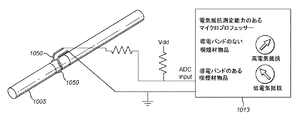
図10〜12は、ハウジング内に収容された喫煙材物品を検知するための抵抗検知が使用される実施態様の例の模式図である。図2および3の例における対応部品と同一であるかまたは少なくとも機能的に似ている構成要素および回路には、「1000」を加えているが同様の参照番号を付している。従って図10〜12で示す例示装置1001は、開口端1003を備える外方ハウジング1002、使用時には喫煙材物品1005を収容する加熱チェンバー1004、電子制御回路1007および動力源1008を含む電子装置/動力チェンバー1006、ヒーター支持スリーブ1009、複数の加熱エレメントまたはヒーターセグメント1010、およびオン/オフスイッチ1011等を含む。これらは全て、図2〜4の模式図の対応構成部品と同一でもよくまたは少なくとも機能的に似ているだけでもよい。異なる加熱構成も可能である。例えば、赤外線を照射して加熱する赤外線ヒーターセグメント1010、またはヒーターセグメント1010周囲にある抵抗性電気巻線などから形成される抵抗性加熱エレメントが挙げられる。さらに別の加熱構成も使用可能である。
10-12 are schematic diagrams of examples of embodiments in which resistance detection is used to detect a smoking article contained within a housing. Components and circuits that are the same or at least functionally similar to corresponding components in the examples of FIGS. 2 and 3 have been added “1000” but have similar reference numerals. Accordingly, the
図10〜12の例では、装置1001は外方ハウジング1002の開口端1003近くに位置する少なくとも2つの導電抵抗接点または電極1050を有する。この2つの電極1050は湾曲しており、ハウジング1002に収容される際に喫煙材物品1005が通過するほぼ円形の開口を画定するようそれぞれの電極1050はほぼ半円形の断面をしている。この2つの電極1050は柔軟性のあるまたは弾力のある材料から形成してもよく、互いに向かい合うように僅かに内向き方向に配置されてよい。こうすることで、喫煙材物品1005が装置1002に導入される際、喫煙材物品1005と物理的に接触し易くなる。
In the example of FIGS. 10-12,
電極1050は接続ワイヤー1014を介して検知回路1013に接続している。検知回路1013は、電子制御回路1007の一部、例えば上述したマイクロプロセッサーなどの制御装置の一部として設けられてもよく、あるいは別個の回路として設けられてもよい。あくまで例示を目的とし限定する意図はないが、図11は、間に喫煙材物品1005が挿入された状態(かつ装置1001の他の部品が省かれた状態の)の電極1050を強調して示す斜視図である。電極1050と検知回路1013との組み合わせが抵抗センサーを供する。
The
電極1050によって効果的に測定される電気抵抗、およびハウジング1002内部に喫煙材物品1005を収容した時に電気抵抗がどのように変化するかをモニターして喫煙材物品1005が「真正」であるか否かの判断を下すことができる。例えば電極1050を通るように参照電圧Vddを加えて、出力電流を検出する電子制御回路1007によってこれを実行してもよい。高い電流は電気抵抗が小さいことを示し、小さい電流は電気抵抗が大きいことを示す。抵抗の絶対的指標が得られる。繰り返しになるが、他の方法も使用可能である。
Whether the
ある実施態様の別の例では、上述した例のいずれかの組み合わせを用いて、容量検知および抵抗検知を組み合わせて使用する。概して、こうすることで喫煙材物品に関してより多くの情報が得られる。これによって得られるべき喫煙材物品のより正確な識別が可能となり、および/または喫煙材物品の中により多くの情報を効果的に暗号化できる。ある特定の実施態様では、これによって、もし何らかの理由で容量検知および抵抗検知の一方がうまく機能しない場合、他方が装置に導入されている喫煙材物品を識別するよう使用され得るという点で、ある程度の重複性を供する。容量検知および抵抗検知は装置の同一の電極を使用して実行してもよく、容量検知および抵抗検知はそれぞれ専用の電極を使用してもよい。 Another example of an embodiment uses a combination of capacitive sensing and resistance sensing using any combination of the above examples. In general, this provides more information about the smoking article. This allows for a more accurate identification of the smoking material article to be obtained and / or more information can be effectively encrypted in the smoking material article. In certain embodiments, this is to some extent in that if for some reason one of capacitive sensing and resistance sensing does not work well, the other can be used to identify a smoking article that has been introduced into the device. Provides redundancy. Capacitance detection and resistance detection may be performed using the same electrode of the apparatus, and capacitance detection and resistance detection may each use a dedicated electrode.
上述した電極は、容量検知用の容量パッドまたは抵抗検知用の抵抗接点などの形状に関係なく、概ね導電性である。容量検知用電極の場合、使用時に喫煙材物品が装置に収容されるまたは接続される時に喫煙材物品と電気的に絶縁されるよう、電極は装置またはハウジング本体中に機械的に配置されることが好ましい。抵抗検知用電極の場合、使用時に喫煙材物品が装置に収容されるまたは接続される時に喫煙材物品と物理的に接触するよう、電極は装置またはハウジング本体中に機械的に配置されることが好ましい。電極に用いられる好適な素材としては銅または銅を含む合金が挙げられる。この中でも容量検知の場合は銅ホイル、抵抗検知の場合はベリリウム−銅合金が好ましい。 The electrodes described above are generally conductive regardless of the shape of a capacitance pad for capacitance detection or a resistance contact for resistance detection. In the case of capacitive sensing electrodes, the electrode must be mechanically placed in the device or housing body so that the smoking material article is electrically insulated from the smoking material article when used or connected to the device in use. Is preferred. In the case of a resistance sensing electrode, the electrode may be mechanically placed in the device or housing body so that the smoking material article is in physical contact with the smoking material article when in use or connected to the device. preferable. Suitable materials used for the electrode include copper or an alloy containing copper. Among these, copper foil is preferable for capacitance detection, and beryllium-copper alloy for resistance detection.
図13において、マーカーまたは印131が設けられたまた形成された喫煙材物品130の例を長軸方向に切断した断面の模式図で示している。マーカーまたは印131の例は後述する。喫煙材物品130は、少なくともいくつかの本明細書で説明する喫煙材の加熱用装置と併せて使用される。印131の配置は特定の加熱用装置において異なってもよく、また別々に最適化してもよい。
In FIG. 13, the example of the
喫煙材物品130は喫煙材ロッド132を有する。上述したように、喫煙材は如何なるタバコ含有材料を含んでもよく、例えばタバコ、タバコ誘導体、膨張タバコ、再構成タバコまたはタバコ代替物の内の1つまたはそれ以上を含んでもよい。また「喫煙材」にはニコチンを含む否かに拘わらず他の非タバコ製品を含んでもよい。喫煙材ロッド132は開口チューブフィルター133に隣接している。ロッド132およびフィルター133は組み合わされ、従来の方法でチッピング紙134に巻かれて一緒に保持される。
The
図示の例では、マーカーまたは印131はチッピング紙134に設けられている。図示の例で印131は、組み立てられた喫煙材物品130において喫煙材物品130を完全に一周する材料からなるバンドの形体である。加熱用装置内における喫煙材物品130の特定の向きが重要ではないので、この構成では上述した加熱用装置の例による印131の性状の測定が簡単になる。他の構成も使用可能である。例えば、必ずしも全ての場合において印131が喫煙材物品130を完全に一周する必要もなく、代わりに印131は規則的もしくは不規則な市松模様または喫煙材物品130を囲む規則的もしくは不規則な間隔を置いて配置されるバンドもしくはストリップなどの別の非連続パターンとして形成されてもよい。図14は、喫煙材物品130を組み立てる前の1つのバンドの印131を有するチッピング紙134の一例を示している。図15は、喫煙材物品130を組み立てる前の実際上2倍幅であり対向縁部に1対のバンドの印131を有するチッピング紙134の一例を示している。製造段階で、対の喫煙材物品130が形成される際に、2倍幅のチッピング紙134は中央から切断される。
In the illustrated example, the marker or mark 131 is provided on the chipping
大きさに関する考えを記載すると、ある特定の例では(喫煙材物品130の長さと平行方向で)喫煙材ロッド132は長さが約53mm、フィルター133は長さが30mm、チッピング紙は幅が35mmである。印131の幅は(再度喫煙材物品130の長さと平行方向で)約4mmである。喫煙材物品の製造工程を邪魔しないように、かつ、加熱用装置に喫煙材物品を挿入しにくくしないように、印131の厚さは薄い方が好ましい。具体的には、印131の厚さは約0.03〜約0.3mmの範囲内であり、より好ましくは約0.03〜約0.05mmの範囲内である。当然のことながら喫煙材物品の表面に印131を埋め込むのであれば、事実上厚さが全くない。他方、満足し得る良好な検知を達成し得るために最小限の厚さが好ましい特定の用途もあり得る。
Stated in terms of size, in one particular example (in a direction parallel to the length of the smoking article 130), the
喫煙材物品130と共に使用されるのが意図された加熱用装置の特定の検知構成に応じて、マーカーまたは印131を数多くの異なる方法で形成してよく、数多くの異なる材料で形成してもよい。例えば、印131は喫煙材物品130の外面に付してもよく、喫煙材物品130の内面に付してもよく、喫煙材物品130の外面および内面の両方に付してもよく、および/またはチッピング紙134の材料中に埋め込んでもよい(限定する意図はなく図示する目的で、図13では印131を強調して示している)。抵抗検知を使用する場合(それのみであるか、容量検知などの他の検知との組み合わせであるかに拘わらず)、加熱用装置の抵抗検知用電極が印131と電気的に良好に接触するように喫煙材物品130の外側に印131が設けられることが好ましい。容量検知を使用する場合、印131を喫煙材物品130の外面および内面に設けてもよく、および/または別個の印131を喫煙材物品130の外面および内面に設けてもよい。マーカーまたは印131は、例えば印刷などによって喫煙材物品130上に文字通り「マーク」されてもよい。これとは別に製造時に喫煙材物品130と一体に形成するなどの別の技術によって、喫煙材物品130中にまたは喫煙材物品130上にマーカーまたは印131を設けてもよい。
Depending on the particular sensing configuration of the heating device intended to be used with the
ある特定の例では、そして喫煙材物品130を検知、識別するため使用される検知方法の特性に応じて、印131は導電性材料で形成される。例えば印131は導電性インクであってもよい。例えばグラビア印刷方法、スクリーン印刷、インクジェット印刷または他の好適な方法で、このインクはチッピング紙134上に印刷されてもよい。
In one particular example, and depending on the characteristics of the sensing method used to detect and identify the
使用時、喫煙材物品130が加熱用装置と関連付けられた際の静電容量の変化を検知するよう配置された容量センサーを使用する加熱用装置、そして特に、実質的にコンデンサの1対の「プレート」を供する(少なくとも)2つの電極を使用する加熱用装置について、以下の事項が関連する。導電性の印またはマーカー131を有する喫煙材物品130は、1つのセンサー電極をもう一方の電極に電気的に連結する独自の回路を形成する。この連結の効果および結果は喫煙材物品130および/または特に印131の生来の電気抵抗Riと静電容量Cによって影響される。一般的に電気抵抗Riは主として、例えば印131に選ばれるインクの種類および組成並びに印131の厚さおよび幅によって決定される。従って、印131のインクの選択は、適用する厚さと同様に、ある幅の範囲に亘りRi特性を制御する方法を供する。一般的に静電容量Cは主として、印131の軸幅および加熱用装置の電極と印131との距離によって決定される。次にこの距離は、電極同士の配置間隔および喫煙材物品130の厚さ(つまり直径)によって決定される。したがって、喫煙材物品130上の検出電極と印131との間の連結または「C」特徴的容量連結は、加熱用装置における喫煙材物品130の「嵌り方」を通して、例えば喫煙材物品130の厚さまたは直径の適切な設定および検出電極の軸幅および印131の軸幅の制御によって、決定または制御される。
In use, a heating device that uses a capacitive sensor arranged to detect a change in capacitance when the
特に好適な材料は、非金属導電性インク、つまり電気的に伝導性であるが金属材料を全く含まないかまたは少なくとも金属材料を実質的に全く含まないインク、であることが判明している。このインクは例えば炭素を含んでもよく、この炭素は黒鉛の形体であってもよい。よってインクは炭素系非金属導電性インクであってもよい。ある特定の例におけるインクの重量電気抵抗は約30,000〜約300,000Ω・g/m2の範囲内である。特に好ましいと判明している例の重量電気抵抗の特定値は、約38,000Ω・g/m2、約150,000Ω・g/m2および約290,000Ω・g/m2である。 A particularly suitable material has been found to be a non-metallic conductive ink, i.e. an ink that is electrically conductive but does not contain any metallic material, or at least contains substantially no metallic material. The ink may contain, for example, carbon, which may be in the form of graphite. Therefore, the ink may be a carbon-based nonmetallic conductive ink. In certain instances, the weight electrical resistance of the ink is in the range of about 30,000 to about 300,000 Ω · g / m 2 . Specific values for gravimetric electrical resistance in examples that have been found to be particularly preferred are about 38,000 Ω · g / m 2 , about 150,000 Ω · g / m 2, and about 290,000 Ω · g / m 2 .
ある特定の例では、インクは黒鉛粉末とバインダーとして機能する樹脂とを主成分として含んでもよいし、これらのみから構成されてもよい。インクは粒径の大きいものから小さいものまでの雑多な集合体である黒鉛を使用してもよい。この中で比較的大きな粒子が電気伝導の主要経路を形成して、比較的小さい粒子が大きい粒子の間の隙間を「充填する」。比較的粒径の大きい粒子を使用すると粒子間の個々の接触点の数を減らすことで通電性は向上する。別の例では、インクはカーボンナノチューブを用いる結晶構造を有している。 In a specific example, the ink may contain graphite powder and a resin functioning as a binder as main components, or may be composed only of these. The ink may be graphite, which is a miscellaneous aggregate from a large particle size to a small particle size. Among these, the relatively large particles form the main path of electrical conduction and the relatively small particles “fill” the gaps between the large particles. When particles having a relatively large particle size are used, the electrical conductivity is improved by reducing the number of individual contact points between the particles. In another example, the ink has a crystal structure using carbon nanotubes.
この目的のため好適なインクには、アメリカ合衆国オハイオ州のEngineered Materials Systems Incが提供するCI−2001およびCI−2004通電性炭素インクが挙げられることが判明している。これらインクは、例えば接触域において物理的もしくは環境的な保護を供するため、または電気抵抗要件を調整するために、印刷回路基板やその類などの印刷電子装置で使用するためのものである。 Suitable inks for this purpose have been found to include CI-2001 and CI-2004 conductive carbon inks provided by Engineered Materials Systems Inc. of Ohio, USA. These inks are for use in printed electronic devices such as printed circuit boards and the like, for example, to provide physical or environmental protection in the contact area, or to adjust electrical resistance requirements.
当該技術分野で周知な技術を含む他の技術と比較して、本発明の実施態様には数多くの優位性がある。本願の検知構成は良好なシグナル/ノイズ比を供する。これは特に容量検知の場合顕著である。信号処理における電気的動力の消費量が減り、より正確により迅速に決定が可能となるので、これは電池駆動装置における特有の利益である。加えて一般的に、喫煙材物品の製造において、喫煙材物品の外径はある範囲に亘り変化するという製造許容誤差がある。そのような変化は実際上例えば2%〜5%程度の場合がある。ある特定の場合では、喫煙材物品の外径は約5.3mm〜約5.45mmで変化する。その程度の変化は、特に本明細書で開示する種々の容量検知配置を含む本願の検知配置によって良く順応される。これは重要な事である。誤って発生し、真正の喫煙材物品が意図せず拒絶されることを招く「見逃し(false negative)」の数を最小限に留めることができるからである。本願の検知配置は、他の技術と比べて、入力/出力接続を減らして使用する電子構成要素を少なくし得るものである。 Compared to other technologies, including those well known in the art, embodiments of the present invention have a number of advantages. The sensing configuration of the present application provides a good signal / noise ratio. This is particularly noticeable in the case of capacity detection. This is a unique benefit in battery-powered devices, since the consumption of electrical power in signal processing is reduced and more accurate and quicker determination is possible. In addition, in general, in the manufacture of smoking article, there is a manufacturing tolerance that the outer diameter of the smoking article changes over a range. Such a change may actually be about 2% to 5%, for example. In certain cases, the outer diameter of the smoking article varies from about 5.3 mm to about 5.45 mm. That degree of change is well accommodated by the present sensing arrangement, particularly including the various capacitive sensing arrangements disclosed herein. This is important. This is because the number of “false negatives” that occur in error and lead to unintentional rejection of authentic smoking material articles can be minimized. The sensing arrangement of the present application can reduce the input / output connections and use fewer electronic components compared to other technologies.
様々な課題を解決し技術を発展させることを目的として、図示を含むこの開示全体は、請求項に係る発明を実施して喫煙材を燃焼させず加熱するよう配置された優れた装置を提供し得る種々の実施形態を示している。この開示の利点および特徴は、実施形態という典型的な例を示すことのみであって、包括的および/または排他的ではない。それらは理解を助けるため、および請求された特徴を教示するためだけに提出される。当然のことながら、開示の利点、実施態様、例示、機能、特徴、構造および/または他の側面は請求項または請求項の均等物の限定によって定義されるように、開示されたものに限定されず、また開示の範囲および/またはその意図から外れない限り他の実施態様を利用しても良く、変更を加えても良い。種々の実施態様は、説明した要素、成分、特徴、部品、工程、手法などの種々の組み合わせを適宜含んでも良いし、それらのみから構成されても良いし、またはそれらを主に構成されても良い。加えて、この開示は現在請求していないが将来請求し得る他の発明を含んでいる。 For the purpose of solving various problems and developing technology, this entire disclosure, including illustrations, provides an excellent apparatus arranged to implement the claimed invention to heat smoking material without burning it. The various embodiments obtained are shown. The advantages and features of this disclosure are merely exemplary of the embodiments and are not exhaustive and / or exclusive. They are submitted only to aid understanding and to teach the claimed features. Of course, the advantages, embodiments, examples, functions, features, structures and / or other aspects of the disclosure are limited to what is disclosed as defined by the claims or equivalents of the claims. And other embodiments may be utilized and modified without departing from the scope and / or intent of the disclosure. Various embodiments may appropriately include various combinations of the described elements, components, features, parts, processes, techniques, or the like, or may be composed solely of them, or may be mainly composed of them. good. In addition, this disclosure includes other inventions that are not currently claimed but may be claimed in the future.
Claims (21)
ハウジングと
使用時に喫煙材物品をハウジングへ導入した際の静電容量の変化を検知し、喫煙材物品の識別を可能にするよう配置された容量センサーと
静電容量の変化が少なくとも1つの所定の基準を満たす場合に使用時にハウジングに導入された喫煙材物品を加熱するためだけに作動させるように構成、配置された回路と
を含む装置。 A device capable of heating a smoking material to volatilize at least one component of the smoking material,
A capacitive sensor arranged to detect the change in capacitance when the smoking material article is introduced into the housing and to allow the smoking material article to be identified during use;
A circuit configured and arranged to operate only to heat a smoking article introduced into the housing in use when the change in capacitance meets at least one predetermined criterion .
ハウジングと
使用において喫煙材物品がハウジングに導入された際の電気抵抗の指標を供し、喫煙材物品の識別を可能にするように配置された抵抗センサーと
電気抵抗が少なくとも1つの所定の基準を満たす場合に使用時にハウジングに導入された喫煙材物品を加熱するためだけに装置を作動させるように構成、配置された回路と
を含む装置。 A device capable of heating a smoking material to volatilize at least one component of the smoking material,
A resistance sensor arranged to provide an indication of electrical resistance when the smoking article is introduced into the housing in use with the housing and to allow identification of the smoking article;
An apparatus comprising: a circuit configured and arranged to operate the apparatus only to heat the smoking article introduced into the housing in use when the electrical resistance meets at least one predetermined criterion .
ハウジングと
少なくとも2つの異なる検知技術を利用して、使用においてハウジングと関連付けられる時の喫煙材物品を識別するよう構成、配置されたセンサー構造と
少なくとも2つの異なる検知技術の検知された値が少なくとも1つの所定の基準を満たす場合に使用時にハウジングに導入された喫煙材物品を加熱するためだけに作動させるように構成、配置された回路と
を含む装置。 A device capable of heating a smoking material to volatilize at least one component of the smoking material,
A sensor structure configured and arranged to identify a smoking article when associated with the housing in use, utilizing at least two different sensing technologies;
A circuit configured and arranged to operate only to heat the smoking article introduced into the housing in use if the detected values of at least two different detection technologies meet at least one predetermined criterion; A device comprising:
Applications Claiming Priority (3)
| Application Number | Priority Date | Filing Date | Title |
|---|---|---|---|
| US201461968780P | 2014-03-21 | 2014-03-21 | |
| US61/968,780 | 2014-03-21 | ||
| PCT/EP2015/055972 WO2015140312A1 (en) | 2014-03-21 | 2015-03-20 | Apparatus for heating smokable material |
Publications (2)
| Publication Number | Publication Date |
|---|---|
| JP2017510270A JP2017510270A (en) | 2017-04-13 |
| JP6348985B2 true JP6348985B2 (en) | 2018-06-27 |
Family
ID=52814070
Family Applications (1)
| Application Number | Title | Priority Date | Filing Date |
|---|---|---|---|
| JP2016558049A Active JP6348985B2 (en) | 2014-03-21 | 2015-03-20 | Apparatus for heating smoking material and article for smoking material |
Country Status (18)
| Country | Link |
|---|---|
| US (3) | US10687553B2 (en) |
| EP (2) | EP4233581A3 (en) |
| JP (1) | JP6348985B2 (en) |
| KR (2) | KR102123900B1 (en) |
| CN (1) | CN106455707B (en) |
| AU (1) | AU2015233388B2 (en) |
| BR (1) | BR112016021596B1 (en) |
| CA (1) | CA2940693C (en) |
| ES (1) | ES2954909T3 (en) |
| HU (1) | HUE062731T2 (en) |
| LT (1) | LT3119224T (en) |
| MY (1) | MY179623A (en) |
| PL (1) | PL3119224T3 (en) |
| PT (1) | PT3119224T (en) |
| RU (1) | RU2656195C2 (en) |
| UA (1) | UA123621C2 (en) |
| WO (1) | WO2015140312A1 (en) |
| ZA (1) | ZA201605859B (en) |
Families Citing this family (96)
| Publication number | Priority date | Publication date | Assignee | Title |
|---|---|---|---|---|
| US10244793B2 (en) | 2005-07-19 | 2019-04-02 | Juul Labs, Inc. | Devices for vaporization of a substance |
| KR101953201B1 (en) | 2011-09-06 | 2019-02-28 | 브리티시 아메리칸 토바코 (인베스트먼츠) 리미티드 | Heating smokeable material |
| US10279934B2 (en) | 2013-03-15 | 2019-05-07 | Juul Labs, Inc. | Fillable vaporizer cartridge and method of filling |
| US10980273B2 (en) | 2013-11-12 | 2021-04-20 | VMR Products, LLC | Vaporizer, charger and methods of use |
| US10159282B2 (en) | 2013-12-23 | 2018-12-25 | Juul Labs, Inc. | Cartridge for use with a vaporizer device |
| KR102130619B1 (en) | 2013-12-23 | 2020-07-07 | 쥴 랩스, 인크. | Vaporization device systems and methods |
| USD825102S1 (en) | 2016-07-28 | 2018-08-07 | Juul Labs, Inc. | Vaporizer device with cartridge |
| US10058129B2 (en) | 2013-12-23 | 2018-08-28 | Juul Labs, Inc. | Vaporization device systems and methods |
| USD842536S1 (en) | 2016-07-28 | 2019-03-05 | Juul Labs, Inc. | Vaporizer cartridge |
| US20160366947A1 (en) | 2013-12-23 | 2016-12-22 | James Monsees | Vaporizer apparatus |
| US10076139B2 (en) | 2013-12-23 | 2018-09-18 | Juul Labs, Inc. | Vaporizer apparatus |
| RU2656195C2 (en) | 2014-03-21 | 2018-05-31 | Бритиш Америкэн Тобэкко (Инвестментс) Лимитед | Apparatus for heating smokable material and article of smokable material |
| KR102520337B1 (en) * | 2014-10-24 | 2023-04-11 | 필립모리스 프로덕츠 에스.에이. | An aerosol-generating device, system and method with a combustion gas detector |
| KR102574658B1 (en) | 2014-12-05 | 2023-09-05 | 쥴 랩스, 인크. | Calibrated dose control |
| US11924930B2 (en) | 2015-08-31 | 2024-03-05 | Nicoventures Trading Limited | Article for use with apparatus for heating smokable material |
| JP6847932B2 (en) * | 2015-09-24 | 2021-03-24 | フィリップ・モーリス・プロダクツ・ソシエテ・アノニム | Aerosol generation system with condenser |
| JP6800961B2 (en) * | 2015-09-24 | 2020-12-16 | フィリップ・モーリス・プロダクツ・ソシエテ・アノニム | Aerosol generator with electrodes for measuring electrical load |
| WO2017139595A1 (en) | 2016-02-11 | 2017-08-17 | Pax Labs, Inc. | Fillable vaporizer cartridge and method of filling |
| EP3419443A4 (en) | 2016-02-11 | 2019-11-20 | Juul Labs, Inc. | Securely attaching cartridges for vaporizer devices |
| EP3413732B1 (en) * | 2016-02-12 | 2020-09-02 | Philip Morris Products S.a.s. | Aerosol-generating system with liquid aerosol-forming substrate identification |
| US10757976B2 (en) | 2016-02-12 | 2020-09-01 | Altria Client Services Llc | Aerosol-generating system with puff detector |
| US20170231277A1 (en) * | 2016-02-12 | 2017-08-17 | Oleg Mironov | Aerosol-generating system with liquid aerosol-forming substrate identification |
| EP3413733A1 (en) * | 2016-02-12 | 2018-12-19 | Philip Morris Products S.a.s. | Aerosol-generating system with puff detector |
| US11006668B2 (en) * | 2016-02-12 | 2021-05-18 | Altria Client Services Llc | Aerosol-generating system with electrodes |
| CN108471811B (en) * | 2016-02-12 | 2021-07-16 | 菲利普莫里斯生产公司 | Aerosol-generating system with electrodes |
| US10405582B2 (en) | 2016-03-10 | 2019-09-10 | Pax Labs, Inc. | Vaporization device with lip sensing |
| US10849360B2 (en) | 2016-04-29 | 2020-12-01 | Altria Client Services Llc | Aerosol-generating device with visual feedback device |
| KR102445554B1 (en) | 2016-04-29 | 2022-09-22 | 필립모리스 프로덕츠 에스.에이. | Aerosol-generating device with visual feedback device |
| USD849996S1 (en) | 2016-06-16 | 2019-05-28 | Pax Labs, Inc. | Vaporizer cartridge |
| USD836541S1 (en) | 2016-06-23 | 2018-12-25 | Pax Labs, Inc. | Charging device |
| USD851830S1 (en) | 2016-06-23 | 2019-06-18 | Pax Labs, Inc. | Combined vaporizer tamp and pick tool |
| US20180070634A1 (en) * | 2016-09-09 | 2018-03-15 | Rai Strategic Holdings, Inc. | Analog control component for an aerosol delivery device |
| EP3515219B1 (en) * | 2016-09-20 | 2022-11-16 | Nicoventures Trading Limited | A method of manufacturing an aerosol provision apparatus and an aerosol provision apparatus |
| CN206491335U (en) * | 2016-10-28 | 2017-09-15 | 深圳市余看智能科技有限公司 | A kind of electronic smoke absorber |
| CN110022702B (en) * | 2016-12-12 | 2022-10-28 | 菲利普莫里斯生产公司 | Product identification in an aerosol-generating device |
| US10952473B2 (en) | 2016-12-22 | 2021-03-23 | Altria Client Services Llc | Aerosol-generating system with pairs of electrodes |
| CN110248562B (en) * | 2017-02-28 | 2022-08-19 | 菲利普莫里斯生产公司 | Aerosol-generating system with electrodes and sensors |
| US11013268B2 (en) * | 2017-02-28 | 2021-05-25 | Altria Client Services Llc | Aerosol-generating system with electrodes and sensors |
| GB201707194D0 (en) | 2017-05-05 | 2017-06-21 | Nicoventures Holdings Ltd | Electronic aerosol provision system |
| JP6813697B2 (en) | 2017-05-11 | 2021-01-13 | ケーティー・アンド・ジー・コーポレーション | Vaporizer and aerosol generator equipped with it |
| KR20180124739A (en) * | 2017-05-11 | 2018-11-21 | 주식회사 케이티앤지 | An aerosol generating device for controlling the temperature of a heater according to the type of cigarette and method thereof |
| CA178743S (en) | 2017-06-26 | 2018-12-12 | Nicoventures Holdings Ltd | Electronic cigarette |
| KR20190049391A (en) | 2017-10-30 | 2019-05-09 | 주식회사 케이티앤지 | Aerosol generating apparatus having heater |
| CN107692317B (en) * | 2017-09-11 | 2019-07-16 | 云南中烟工业有限责任公司 | A kind of device that can light or heat automatically cigarette |
| USD887632S1 (en) | 2017-09-14 | 2020-06-16 | Pax Labs, Inc. | Vaporizer cartridge |
| KR101983040B1 (en) * | 2017-09-26 | 2019-05-30 | 전자부품연구원 | Adiabatic tube and electric heating type smoking device using the same |
| US11099213B2 (en) * | 2017-10-20 | 2021-08-24 | Infineon Technologies Ag | Readout circuit for resistive and capacitive sensors |
| KR102138246B1 (en) | 2017-10-30 | 2020-07-28 | 주식회사 케이티앤지 | Vaporizer and aerosol generating apparatus comprising the same |
| RU2738549C1 (en) | 2017-10-30 | 2020-12-14 | Кейтиэндджи Корпорейшн | Device for aerosol generation and method of such device control |
| KR102057215B1 (en) | 2017-10-30 | 2019-12-18 | 주식회사 케이티앤지 | Method and apparatus for generating aerosols |
| KR102057216B1 (en) | 2017-10-30 | 2019-12-18 | 주식회사 케이티앤지 | An apparatus for generating aerosols and A heater assembly therein |
| JP6978580B2 (en) | 2017-10-30 | 2021-12-08 | ケイティー アンド ジー コーポレイション | Heaters for aerosol generators and aerosol generators |
| JP6840289B2 (en) | 2017-10-30 | 2021-03-10 | ケイティー アンド ジー コーポレイション | Aerosol generator |
| KR102180421B1 (en) | 2017-10-30 | 2020-11-18 | 주식회사 케이티앤지 | Apparatus for generating aerosols |
| KR102138245B1 (en) | 2017-10-30 | 2020-07-28 | 주식회사 케이티앤지 | Aerosol generating apparatus |
| CN110996692B (en) | 2017-10-30 | 2023-09-08 | 韩国烟草人参公社 | Aerosol generating device |
| DE102017222528B3 (en) | 2017-12-12 | 2019-01-24 | Heraeus Sensor Technology Gmbh | Heating unit for a system for providing an inhalable aerosol |
| TW201931945A (en) * | 2017-12-29 | 2019-08-01 | 瑞士商傑太日煙國際股份有限公司 | Heating assembly for a vapour generating device |
| GB201805234D0 (en) * | 2018-03-29 | 2018-05-16 | Nicoventures Trading Ltd | Aerosol generating device |
| GB201805257D0 (en) | 2018-03-29 | 2018-05-16 | Nicoventures Holdings Ltd | An aerosol delivery device, an article for use therewith, and a method of identifying an article |
| GB201805170D0 (en) * | 2018-03-29 | 2018-05-16 | Nicoventures Holdings Ltd | Electronic aerosol provision system |
| GB201805266D0 (en) * | 2018-03-29 | 2018-05-16 | Nicoventures Trading Ltd | Apparatus for generating aerosol from an aerosolisable medium and article of aerosolisable medium |
| CN108572202B (en) * | 2018-03-30 | 2020-10-27 | 深圳麦克韦尔科技有限公司 | Electronic cigarette state detection device and method and electronic cigarette |
| KR102447360B1 (en) * | 2018-04-25 | 2022-09-26 | 주식회사 케이티앤지 | Aerosols generating apparatus |
| WO2019224310A1 (en) * | 2018-05-25 | 2019-11-28 | Jt International Sa | Vapour generating device with sensors to measure strain generated by a vapour generating material |
| KR102323786B1 (en) * | 2018-06-18 | 2021-11-09 | 주식회사 이엠텍 | Fine particle generator |
| GB201810994D0 (en) * | 2018-07-04 | 2018-08-15 | British American Tobacco Investments Ltd | A consumable article for use with an apparatus for heating aersolisable material |
| KR102275097B1 (en) * | 2018-07-18 | 2021-07-08 | 주식회사 케이티앤지 | Aerosol generating apparatus and heater assembly thereof |
| EP3836811B1 (en) * | 2018-08-17 | 2022-10-05 | Philip Morris Products S.A. | Aerosol-generating device for use with an aerosol-generating article comprising means for article identification |
| US10939707B2 (en) | 2018-08-23 | 2021-03-09 | Rai Strategic Holdings, Inc. | Aerosol delivery device with segmented electrical heater |
| US11930377B2 (en) | 2018-10-05 | 2024-03-12 | Samsung Electronics Co., Ltd. | Method and system for enabling distributed caching in wireless network |
| WO2020084756A1 (en) * | 2018-10-26 | 2020-04-30 | 日本たばこ産業株式会社 | Electronic device and method and program for operating electronic device |
| US20220087322A1 (en) * | 2018-12-20 | 2022-03-24 | Nicoventures Trading Limited | Aerosol provision system |
| GB201901066D0 (en) * | 2019-01-25 | 2019-03-13 | Nicoventures Trading Ltd | Aerosol generating apparatus, aerosol generating article and method of determining data associated with an aerosol generating article |
| JP7357071B2 (en) * | 2019-04-04 | 2023-10-05 | ニコベンチャーズ トレーディング リミテッド | Casings, devices, and methods for devices |
| KR20200144049A (en) | 2019-06-17 | 2020-12-28 | 주식회사 케이티앤지 | An aerosol generating device and an aerosol generating article |
| RU2766077C1 (en) | 2019-06-27 | 2022-02-07 | Хзат, Ллк | Compositions of a tobacco product and delivery system |
| KR102337229B1 (en) * | 2019-08-05 | 2021-12-08 | 주식회사 케이티앤지 | Aerosol generating device and Aerosol generating system including the same |
| GB2586255A (en) | 2019-08-14 | 2021-02-17 | E Breathe Ltd | Improvements relating to aerosol generating systems |
| WO2021141251A1 (en) * | 2020-01-06 | 2021-07-15 | Kt&G Corporation | Aerosol generating device |
| CN111418900B (en) * | 2020-03-20 | 2023-11-03 | 深圳麦克韦尔科技有限公司 | Tobacco tar nicotine content detection system, method and device and electronic atomization device |
| DE102020110031A1 (en) * | 2020-04-09 | 2021-10-14 | Xeotech Gmbh | Device for generating an inhalable aerosol |
| KR102451070B1 (en) * | 2020-06-03 | 2022-10-05 | 주식회사 케이티앤지 | Apparatus for generating aerosol based on external heating |
| WO2021249833A1 (en) * | 2020-06-12 | 2021-12-16 | Jt International S.A. | Method and system for identifying aerosol-generating articles |
| EP4164437A1 (en) * | 2020-06-12 | 2023-04-19 | JT International S.A. | Method and system for identifying smoking articles |
| US20220264957A1 (en) * | 2020-07-31 | 2022-08-25 | Kt&G Corporation | Aerosol generating device including an electrode |
| CN114098166A (en) * | 2020-09-01 | 2022-03-01 | 深圳市合元科技有限公司 | Aerosol generating device and infrared heater |
| CN112315031A (en) * | 2020-11-20 | 2021-02-05 | 河南中烟工业有限责任公司 | Cigarette detection method based on interelectrode capacitance dielectric constant change |
| WO2022167583A1 (en) | 2021-02-08 | 2022-08-11 | Jt International S.A. | An aerosol generating device, an aerosol generating system and a method for controlling the heating of such an aerosol generating device |
| WO2022195769A1 (en) * | 2021-03-17 | 2022-09-22 | 日本たばこ産業株式会社 | Suction device, program, and system |
| KR20230011091A (en) * | 2021-07-13 | 2023-01-20 | 주식회사 케이티앤지 | Aerosol generating device |
| WO2023075558A1 (en) * | 2021-11-01 | 2023-05-04 | Kt&G Corporation | Aerosol generating device and system including the same |
| KR20230063377A (en) | 2021-11-02 | 2023-05-09 | 주식회사 케이티앤지 | Sidestream smoke removal device including smoking article recognition unit |
| WO2023127326A1 (en) * | 2021-12-28 | 2023-07-06 | 日本たばこ産業株式会社 | Non-combustion flavor inhaler |
| WO2023157123A1 (en) * | 2022-02-16 | 2023-08-24 | 日本たばこ産業株式会社 | Aerosol generation system, control method, and program |
| CN114568763A (en) * | 2022-03-04 | 2022-06-03 | 深圳麦时科技有限公司 | Aerosol generating device and atomization control device thereof |
Family Cites Families (26)
| Publication number | Priority date | Publication date | Assignee | Title |
|---|---|---|---|---|
| JPH02301759A (en) * | 1989-05-16 | 1990-12-13 | Sharp Corp | Image forming device provided with for giving glossiness to image |
| GB8915972D0 (en) | 1989-07-12 | 1989-08-31 | Kratos Analytical Ltd | An ion mirror for a time-of-flight mass spectrometer |
| EP0553699A1 (en) | 1992-01-30 | 1993-08-04 | Hauni Maschinenbau Aktiengesellschaft | Apparatus for testing the ends of cigarettes |
| UA49831C2 (en) | 1995-04-20 | 2002-10-15 | Філіп Морріс Продактс Інк | Electrical smoking system (variants), cigarette (variants) and heater used in this system, method of improvement of smoke production, tobacco envelope (variants) and method for production of tobacco envelope |
| US5902501A (en) * | 1997-10-20 | 1999-05-11 | Philip Morris Incorporated | Lighter actuation system |
| JPH11346747A (en) * | 1998-06-12 | 1999-12-21 | Japan Tobacco Inc | Device for winding up tobacco |
| JP2002007992A (en) | 2000-04-21 | 2002-01-11 | Sagawa Insatsu Kk | Electronic tag |
| US20020000225A1 (en) | 2000-06-02 | 2002-01-03 | Carlos Schuler | Lockout mechanism for aerosol drug delivery devices |
| US20020048621A1 (en) * | 2000-10-06 | 2002-04-25 | Boyd David D. | Encoded coffee packet |
| CN100381083C (en) * | 2003-04-29 | 2008-04-16 | 韩力 | Electronic nonflammable spraying cigarette |
| US8186359B2 (en) * | 2008-02-01 | 2012-05-29 | R. J. Reynolds Tobacco Company | System for analyzing a filter element associated with a smoking article, and associated method |
| EP2110033A1 (en) * | 2008-03-25 | 2009-10-21 | Philip Morris Products S.A. | Method for controlling the formation of smoke constituents in an electrical aerosol generating system |
| EP2143346A1 (en) | 2008-07-08 | 2010-01-13 | Philip Morris Products S.A. | A flow sensor system |
| EP2201850A1 (en) | 2008-12-24 | 2010-06-30 | Philip Morris Products S.A. | An article including identification information for use in an electrically heated smoking system |
| US8360801B2 (en) * | 2009-01-21 | 2013-01-29 | Apple Inc. | Contactless plug detect mechanism |
| CN103827650A (en) * | 2011-08-04 | 2014-05-28 | 如烟投资(控股)有限公司 | A capacitor sensor, devices employing the capacitor sensor and methods for their use |
| JP2014530632A (en) * | 2011-10-27 | 2014-11-20 | フィリップ・モーリス・プロダクツ・ソシエテ・アノニム | Aerosol generation system with improved aerosol generation |
| JP5611172B2 (en) * | 2011-11-08 | 2014-10-22 | 三菱電機株式会社 | Hand dryer |
| RU2618436C2 (en) * | 2011-12-30 | 2017-05-03 | Филип Моррис Продактс С.А. | Generation system of aerosol consumption control and feedback |
| GB2502053B (en) | 2012-05-14 | 2014-09-24 | Nicoventures Holdings Ltd | Electronic smoking device |
| CN203033452U (en) * | 2012-12-11 | 2013-07-03 | 浙江中烟工业有限责任公司 | Monitoring device of filter stick pneumatic conveying pipeline |
| WO2014201432A1 (en) | 2013-06-14 | 2014-12-18 | Ploom, Inc. | Multiple heating elements with separate vaporizable materials in an electric vaporization device |
| RU2656195C2 (en) | 2014-03-21 | 2018-05-31 | Бритиш Америкэн Тобэкко (Инвестментс) Лимитед | Apparatus for heating smokable material and article of smokable material |
| TWI692274B (en) * | 2014-05-21 | 2020-04-21 | 瑞士商菲利浦莫里斯製品股份有限公司 | Inductive heating device for heating an aerosol-forming substrate and method of operating an inductive heating system |
| JP6924180B2 (en) * | 2015-09-24 | 2021-08-25 | フィリップ・モーリス・プロダクツ・ソシエテ・アノニム | Aerosol generating article with condenser |
| US11006668B2 (en) * | 2016-02-12 | 2021-05-18 | Altria Client Services Llc | Aerosol-generating system with electrodes |
-
2015
- 2015-03-20 RU RU2016137560A patent/RU2656195C2/en active
- 2015-03-20 AU AU2015233388A patent/AU2015233388B2/en active Active
- 2015-03-20 EP EP23178072.7A patent/EP4233581A3/en active Pending
- 2015-03-20 ES ES15714436T patent/ES2954909T3/en active Active
- 2015-03-20 BR BR112016021596-6A patent/BR112016021596B1/en active IP Right Grant
- 2015-03-20 UA UAA201609527A patent/UA123621C2/en unknown
- 2015-03-20 US US15/127,204 patent/US10687553B2/en active Active
- 2015-03-20 CN CN201580015478.4A patent/CN106455707B/en active Active
- 2015-03-20 MY MYPI2016703296A patent/MY179623A/en unknown
- 2015-03-20 KR KR1020197003146A patent/KR102123900B1/en active IP Right Grant
- 2015-03-20 CA CA2940693A patent/CA2940693C/en active Active
- 2015-03-20 WO PCT/EP2015/055972 patent/WO2015140312A1/en active Application Filing
- 2015-03-20 KR KR1020167025874A patent/KR101971169B1/en active IP Right Grant
- 2015-03-20 EP EP15714436.1A patent/EP3119224B1/en active Active
- 2015-03-20 LT LTEPPCT/EP2015/055972T patent/LT3119224T/en unknown
- 2015-03-20 JP JP2016558049A patent/JP6348985B2/en active Active
- 2015-03-20 PL PL15714436.1T patent/PL3119224T3/en unknown
- 2015-03-20 PT PT157144361T patent/PT3119224T/en unknown
- 2015-03-20 HU HUE15714436A patent/HUE062731T2/en unknown
-
2016
- 2016-08-23 ZA ZA2016/05859A patent/ZA201605859B/en unknown
-
2020
- 2020-05-06 US US15/929,508 patent/US11849769B2/en active Active
-
2023
- 2023-05-19 US US18/320,471 patent/US20230301362A1/en active Pending
Also Published As
Similar Documents
| Publication | Publication Date | Title |
|---|---|---|
| JP6348985B2 (en) | Apparatus for heating smoking material and article for smoking material | |
| JP7209071B2 (en) | Electric heating smoking system with improved heater | |
| KR102595270B1 (en) | Heater Management | |
| KR102500006B1 (en) | Aerosol generator with multiple heaters | |
| JP2023103473A (en) | Apparatus for generating aerosol from aerosolizable medium, article of aerosolizable medium, and method of determining parameter of article | |
| JP6875044B2 (en) | Device for heating smoking material | |
| DK3145340T3 (en) | AEROSOLIC ARTICLE CONTAINING MAGNETIC PARTICLES | |
| JP2023082118A (en) | Apparatus for generating aerosol from aerosolisable medium, article of aerosolisable medium and method of operating aerosol generating apparatus | |
| KR20170129710A (en) | Heater management | |
| EP3923754A1 (en) | Aerosol-generating device having capacitance based power control | |
| CN111918566B (en) | Aerosol generating device | |
| JP2022549078A (en) | Consumables for use with devices for heating aerosolizable materials | |
| EP4017303A1 (en) | An aerosol-generating system and an interface element for an aerosol-generating system | |
| JP2022517777A (en) | Methods for determining aerosol generators, aerosol-producing articles, and data related to aerosol-producing articles. | |
| KR20240011698A (en) | Aerosol-generating article with biomarker sensor | |
| WO2023242254A1 (en) | Method for manufacturing sensor for aerosol-generating device |
Legal Events
| Date | Code | Title | Description |
|---|---|---|---|
| A529 | Written submission of copy of amendment under article 34 pct |
Free format text: JAPANESE INTERMEDIATE CODE: A529 Effective date: 20161104 |
|
| A621 | Written request for application examination |
Free format text: JAPANESE INTERMEDIATE CODE: A621 Effective date: 20161104 |
|
| A977 | Report on retrieval |
Free format text: JAPANESE INTERMEDIATE CODE: A971007 Effective date: 20170823 |
|
| A131 | Notification of reasons for refusal |
Free format text: JAPANESE INTERMEDIATE CODE: A131 Effective date: 20171010 |
|
| A521 | Request for written amendment filed |
Free format text: JAPANESE INTERMEDIATE CODE: A523 Effective date: 20180105 |
|
| TRDD | Decision of grant or rejection written | ||
| A01 | Written decision to grant a patent or to grant a registration (utility model) |
Free format text: JAPANESE INTERMEDIATE CODE: A01 Effective date: 20180508 |
|
| A61 | First payment of annual fees (during grant procedure) |
Free format text: JAPANESE INTERMEDIATE CODE: A61 Effective date: 20180601 |
|
| R150 | Certificate of patent or registration of utility model |
Ref document number: 6348985 Country of ref document: JP Free format text: JAPANESE INTERMEDIATE CODE: R150 |
|
| S111 | Request for change of ownership or part of ownership |
Free format text: JAPANESE INTERMEDIATE CODE: R313113 |
|
| R350 | Written notification of registration of transfer |
Free format text: JAPANESE INTERMEDIATE CODE: R350 |
|
| R250 | Receipt of annual fees |
Free format text: JAPANESE INTERMEDIATE CODE: R250 |
|
| R250 | Receipt of annual fees |
Free format text: JAPANESE INTERMEDIATE CODE: R250 |
|
| R250 | Receipt of annual fees |
Free format text: JAPANESE INTERMEDIATE CODE: R250 |