JP6348404B2 - Thermal / sonic conversion parts and thermal / sonic conversion units - Google Patents
Thermal / sonic conversion parts and thermal / sonic conversion units Download PDFInfo
- Publication number
- JP6348404B2 JP6348404B2 JP2014229094A JP2014229094A JP6348404B2 JP 6348404 B2 JP6348404 B2 JP 6348404B2 JP 2014229094 A JP2014229094 A JP 2014229094A JP 2014229094 A JP2014229094 A JP 2014229094A JP 6348404 B2 JP6348404 B2 JP 6348404B2
- Authority
- JP
- Japan
- Prior art keywords
- heat
- wave conversion
- sonic wave
- honeycomb
- conversion component
- Prior art date
- Legal status (The legal status is an assumption and is not a legal conclusion. Google has not performed a legal analysis and makes no representation as to the accuracy of the status listed.)
- Active
Links
Images


Classifications
-
- F—MECHANICAL ENGINEERING; LIGHTING; HEATING; WEAPONS; BLASTING
- F03—MACHINES OR ENGINES FOR LIQUIDS; WIND, SPRING, OR WEIGHT MOTORS; PRODUCING MECHANICAL POWER OR A REACTIVE PROPULSIVE THRUST, NOT OTHERWISE PROVIDED FOR
- F03G—SPRING, WEIGHT, INERTIA OR LIKE MOTORS; MECHANICAL-POWER PRODUCING DEVICES OR MECHANISMS, NOT OTHERWISE PROVIDED FOR OR USING ENERGY SOURCES NOT OTHERWISE PROVIDED FOR
- F03G7/00—Mechanical-power-producing mechanisms, not otherwise provided for or using energy sources not otherwise provided for
- F03G7/025—Mechanical-power-producing mechanisms, not otherwise provided for or using energy sources not otherwise provided for characterised by its use
- F03G7/0252—Motors; Energy harvesting or waste energy recovery
-
- F—MECHANICAL ENGINEERING; LIGHTING; HEATING; WEAPONS; BLASTING
- F03—MACHINES OR ENGINES FOR LIQUIDS; WIND, SPRING, OR WEIGHT MOTORS; PRODUCING MECHANICAL POWER OR A REACTIVE PROPULSIVE THRUST, NOT OTHERWISE PROVIDED FOR
- F03G—SPRING, WEIGHT, INERTIA OR LIKE MOTORS; MECHANICAL-POWER PRODUCING DEVICES OR MECHANISMS, NOT OTHERWISE PROVIDED FOR OR USING ENERGY SOURCES NOT OTHERWISE PROVIDED FOR
- F03G7/00—Mechanical-power-producing mechanisms, not otherwise provided for or using energy sources not otherwise provided for
- F03G7/002—Mechanical-power-producing mechanisms, not otherwise provided for or using energy sources not otherwise provided for using the energy of vibration of fluid columns
Landscapes
- Engineering & Computer Science (AREA)
- Chemical & Material Sciences (AREA)
- Combustion & Propulsion (AREA)
- Mechanical Engineering (AREA)
- General Engineering & Computer Science (AREA)
- Heat-Exchange Devices With Radiators And Conduit Assemblies (AREA)
Description
本発明は、熱・音波変換部品および熱・音波変換ユニットに関する。さらに詳しくは、熱と音波のエネルギーとを相互に変換する熱・音波変換部品、および、熱・音波変換部品と熱交換器で構成された熱・音波変換ユニットに関する。 The present invention relates to a heat / sonic wave conversion component and a heat / sonic wave conversion unit. More specifically, the present invention relates to a heat / sonic wave conversion component that mutually converts heat and sound wave energy, and a heat / sonic wave conversion unit that includes a heat / sonic wave conversion component and a heat exchanger.
近年、社会全体でエネルギー資源の有効活用の要請が高まってきており、エネルギーを再利用する様々な技術の開発が試みられている。その中でも、熱音響効果を利用して自動車の排気ガス等の高温流体の熱を音波のエネルギーに変換し、そのエネルギーを最終的に電力等の形で出力するエネルギーリサイクルシステムは、得られるエネルギーの取得率(エネルギー効率)が高いことから注目を集めており、実用化に向けて様々な工夫が行われている。 In recent years, there has been an increasing demand for effective use of energy resources throughout the society, and development of various technologies for reusing energy has been attempted. Among them, by utilizing the thermoacoustic effect converts heat of the high-temperature fluid such as exhaust gas of automobile acoustic energy, energy recycling system to output the energy in the form of such final power is obtained energy It has been attracting attention because of its high acquisition rate (energy efficiency), and various efforts have been made for practical application.
熱音響効果は、簡単に言えば、熱により音波が発生する現象であり、より詳しく言えば、細管の一端部に熱を与えて細管に温度勾配を形成することで細管中の音波伝播媒体が振動を起こして音波が発生する現象である。このとき一度に数多くの細管を用いて音波が発生させると効率がよいことから、熱音響効果を起こす細管の集合体として、孔径の小さい貫通孔が数多く形成されたハニカム構造体が採用されることが多い(たとえば、特許文献1〜3参照)。 In short, the thermoacoustic effect is a phenomenon in which sound waves are generated by heat. More specifically, the sound propagation medium in the narrow tubes is formed by applying heat to one end of the narrow tubes to form a temperature gradient in the narrow tubes. This is a phenomenon in which sound waves are generated by vibration. At this time, since it is efficient to generate sound waves using a large number of thin tubes at a time, a honeycomb structure having a large number of through-holes with a small hole diameter is adopted as an assembly of thin tubes that cause a thermoacoustic effect. There are many (for example, refer patent documents 1-3).
ところで、ハニカム構造体自体は、その表面積の大きい立体形状を利用する目的で、熱音響効果とは無関係に、様々な用途について用いられてきた。たとえば、自動車の排気ガスから微粒子を取り除く排気浄化触媒担持用のハニカム構造体は、その典型的な例であり、従来から様々なタイプのものが開発されている。また、他の例としては、イオン触媒体として利用するために、孔径が数十〜数百μmの小さい貫通孔を持つハニカム構造体も開発されており(たとえば、非特許文献1,2参照)、これらは、フィルタ目的のハニカム構造体で通常用いられる押出成形法とは全く異なり、専ら化学的な手法を用いて作製される。
By the way, the honeycomb structure itself has been used for various uses irrespective of the thermoacoustic effect in order to use a three-dimensional shape having a large surface area. For example, the honeycomb structure of the exhaust purification catalyst carrying fine particles are removed from the exhaust gas of an automobile is a typical example, a conventionally various types have been developed. As another example, a honeycomb structure having a small through hole with a pore diameter of several tens to several hundreds of μm has been developed for use as an ion catalyst (see, for example, Non-Patent
このように、従来からよく知られたハニカム構造体ではあるが、熱音響効果を起こす熱・音波変換部品として用いるには、熱音響効果発生に適した特有の特性を持つことが要求される。たとえば、高い熱音響効果を発揮するためには、貫通孔の孔径を小さくすることが好ましく、特許文献3では、排気浄化触媒担持用のハニカム構造体よりも貫通孔の孔径の小さい0.5mm以上1.0mm未満程度の孔径の熱音響効果用のハニカム構造体が提案されている。非特許文献1,2のハニカム構造体では孔径がきわめて小さいものの、専ら化学的な手法を用いて作製されるため、その長さや耐久性に限界があり熱音響効果用のハニカム構造体にはあまり適さないのに対し、この特許文献3の熱音響効果用のハニカム構造体は、熱音響効果を発揮する熱・音波変換部品としての利用に耐えられるという必要条件を満たしつつ、高い熱・音波変換機能を有するという長所を有している。
As described above, although it is a conventionally well-known honeycomb structure, in order to use it as a heat / sonic wave conversion part that generates a thermoacoustic effect, it is required to have specific characteristics suitable for generating a thermoacoustic effect. For example, in order to exert a high thermoacoustic effect, it is preferable to reduce the hole diameter of the through hole. In
しかしながら、熱・音波変換機能の向上に寄与する要素としては、貫通孔の孔径を小さくする以外にも構造上の様々な要素が考えられる。たとえば、高い熱・音波変換機能が継続的に発揮されるためには、ハニカム構造体の両端部間に形成された温度勾配を十分に維持することが要求されるが、温度勾配を十分に維持するに当たっては、ハニカム構造体端部を加熱する外部の加熱機構の能力向上とは別に、ハニカム構造体それ自体の構造を工夫することが要求される。このように、熱・音波変換機能の向上については、さらなる改良が望まれる。 However, as elements contributing to the improvement of the heat / sonic wave conversion function, various structural elements can be considered in addition to reducing the diameter of the through holes. For example, in order to continuously exhibit a high thermal / sonic wave conversion function, it is required to maintain a sufficient temperature gradient formed between both ends of the honeycomb structure, but the temperature gradient is sufficiently maintained. In doing so, it is required to devise the structure of the honeycomb structure itself, in addition to improving the capability of an external heating mechanism for heating the end of the honeycomb structure. Thus, further improvement is desired for the improvement of the heat / sonic wave conversion function.
上記の事情を鑑み、本発明は、温度勾配の維持に適した構造を有する熱・音波変換部品、および、このような熱・音波変換部品と熱交換器で構成された熱・音波変換ユニットを提供することを目的とする。 In view of the above circumstances, the present invention provides a heat / sonic wave conversion component having a structure suitable for maintaining a temperature gradient, and a heat / sonic wave conversion unit including such a heat / sonic wave conversion component and a heat exchanger. The purpose is to provide.
上述の課題を解決するため、本発明は、以下の熱・音波変換部品、および、熱・音波変換ユニットを提供する。 In order to solve the above-described problems, the present invention provides the following thermal / sonic wave conversion component and thermal / sonic wave conversion unit.
[1] 第1の端面から第2の端面まで延在する複数のセルであって、振動することで音波を伝搬する作動流体によって内部が満たされる複数のセルを区画形成する隔壁を有し、該隔壁と前記作動流体との間で授受される熱と、前記作動流体の振動による音波のエネルギーとを相互に変換する熱・音波変換部品であって、前記セルの延在方向に垂直な前記セルの断面の面積をS、該断面の周長をCとしたときにHD=4×S/Cで定義される水力直径HDが0.4mm以下であり、前記熱・音波変換部品の各端面における開口率が60%以上93%以下であり、前記熱・音波変換部品の、前記延在方向に沿った単位長さ当たりの熱容量は、前記延在方向に沿って前記第1の端面から離れるほど減少する傾向を示すものであり、前記延在方向に沿った前記熱・音波変換部品の全長の10%の領域を占める、前記第1の端面側の第1端部の熱容量は、前記延在方向に沿った前記熱・音波変換部品の全長の10%の領域を占める、前記第2の端面側の第2端部の熱容量の1.1倍以上である熱・音波変換部品。 [1] A plurality of cells extending from the first end surface to the second end surface, each having a partition wall that partitions and forms a plurality of cells that are filled with a working fluid that propagates sound waves by vibration. A heat / sonic wave conversion component that mutually converts heat transferred between the partition wall and the working fluid and sound wave energy generated by the vibration of the working fluid, and is perpendicular to the cell extending direction. When the area of the cross section of the cell is S and the circumference of the cross section is C, the hydraulic diameter HD defined by HD = 4 × S / C is 0.4 mm or less, and each end face of the thermal / sonic wave conversion component The heat capacity per unit length along the extending direction of the heat / sonic wave conversion component is separated from the first end surface along the extending direction. and shows a tendency to decrease as, along the extending direction And accounts for 10 percent of the total length of the heat-wave conversion parts, the heat capacity of the first end portion of the first end face side, 10% of the total length of the heat-wave conversion part along the extending direction A heat / sonic wave conversion component that occupies the region of 1.1 and is 1.1 times or more the heat capacity of the second end portion on the second end face side.
[2] 2つの端面の間を延在する複数のセルであって、前記作動流体によって内部が満たされる複数のセルを区画形成する隔壁を有し、該隔壁と前記作動流体との間で授受される熱と、前記作動流体の振動による音波のエネルギーとを相互に変換する、それぞれが一体的に形成された複数のハニカムセグメントを備え、前記熱・音波変換部品は、前記複数のハニカムセグメントが、各ハニカムセグメントの一端面が前記複数のハニカムセグメントのうちの別のハニカムセグメントの一端面に当接した状態で前記第1の端面から前記第2の端面まで直列的に配置されることで構成されたものであり、前記複数のハニカムセグメントそれぞれの前記セルの水力直径は0.4mm以下であり、前記複数のハニカムセグメントそれぞれの各端面における開口率は60%以上93%以下であり、前記複数のハニカムセグメントは、前記延在方向に沿った単位長さ当たりの熱容量が互いに異なるものであって、前記第1端部の側から前記第2端部の側に向かって、前記延在方向に沿った単位長さ当たりの熱容量の大きい順に直列的に配置されているものであり、直列的に配置された前記複数のハニカムセグメントのうちの、前記第1の端面を端面として持つ第1のハニカムセグメントは、前記熱・音波変換部品の前記第1端部を含むものであり、直列的に配置された前記複数のハニカムセグメントのうちの、前記第2の端面を端面として持つ第2のハニカムセグメントは、前記熱・音波変換部品の前記第2端部を含むものである[1]記載の熱・音波変換部品。ここで、「各ハニカムセグメントの一端面が前記複数のハニカムセグメントのうちの別のハニカムセグメントの一端面に当接した状態」には、隣接する2つのハニカムセグメントの端面が互いに直接に接触している状態に加え、接合材をおいて互いに対向している状態や、音波の伝達に支障が生じない程度の微小な間隔を置いて互いに対向している状態が含まれている。 [2] A plurality of cells extending between two end faces, each having a partition wall defining a plurality of cells filled with the working fluid, and exchanged between the partition wall and the working fluid A plurality of honeycomb segments that are integrally formed with each other, and each of the plurality of honeycomb segments is formed integrally with the heat and sound wave conversion component. , composed by one end face of each honeycomb segment is arranged in series to one end face of another honeycomb segment from the first end surface in contact state to said second end surface of the plurality of honeycomb segments The hydraulic diameter of the cells of each of the plurality of honeycomb segments is 0.4 mm or less, and each end face of each of the plurality of honeycomb segments is The opening ratio is not less than 60% and not more than 93%, and the plurality of honeycomb segments have different heat capacities per unit length along the extending direction, and the first end portion side A plurality of honeycomb segments arranged in series are arranged in series in descending order of heat capacity per unit length along the extending direction toward the second end side. The first honeycomb segment having the first end surface as an end surface includes the first end portion of the thermal / sonic wave conversion component, and is included in the plurality of honeycomb segments arranged in series. The second honeycomb segment having the second end face as an end face includes the second end portion of the heat / sonic wave conversion part [1]. Here, in the “state where one end face of each honeycomb segment is in contact with one end face of another honeycomb segment among the plurality of honeycomb segments”, the end faces of two adjacent honeycomb segments are in direct contact with each other. In addition to the present state, there are a state in which the bonding materials are opposed to each other and a state in which the bonding materials are opposed to each other with a minute interval that does not hinder the transmission of sound waves.
[3] 前記第1のハニカムセグメントの単位体積当たりの熱容量は、前記第2のハニカムセグメントの単位体積当たりの熱容量と同じであり、前記第1のハニカムセグメントの円相当直径は、前記第2のハニカムセグメントの円相当直径の1.05倍以上である[2]記載の熱・音波変換部品。 [3] The heat capacity per unit volume of the first honeycomb segment is the same as the heat capacity per unit volume of the second honeycomb segment, and the equivalent-circle diameter of the first honeycomb segment is the second The heat / sonic wave conversion component according to [2], which is 1.05 times or more the circle equivalent diameter of the honeycomb segment.
[4] 前記第1のハニカムセグメントの単位体積当たりの熱容量は、前記第2のハニカムセグメントの単位体積当たりの熱容量の1.1倍以上であり、前記第1のハニカムセグメントの円相当直径は、前記第2のハニカムセグメントの円相当直径と同じである[2]記載の熱・音波変換部品。 [4] The heat capacity per unit volume of the first honeycomb segment is 1.1 times or more the heat capacity per unit volume of the second honeycomb segment, and the equivalent circle diameter of the first honeycomb segment is The thermal / sonic wave conversion component according to [2], which has the same circle equivalent diameter as the second honeycomb segment.
[5] [1]〜[4]のいずれかに記載の熱・音波変換部品であって、前記作動流体が前記複数のセルの内部を満たしている状態において前記第1端部と前記第2端部との間に温度差が生じたときに、該温度差に応じて前記作動流体を前記延在方向に沿って振動させて音波を発生する熱・音波変換部品と、前記熱・音波変換部品の前記第1端部および前記第2端部にそれぞれ近接して設けられ、該両端部との間で熱の授受を行うことで該両端部の間に温度差を与える一対の熱交換部と、を備えた熱・音波変換ユニット。 [5] The heat / sonic wave conversion component according to any one of [1] to [4], wherein the first end portion and the second portion are in a state where the working fluid fills the inside of the plurality of cells. When a temperature difference occurs between the end portion and the heat / sonic wave conversion component that generates a sound wave by vibrating the working fluid along the extending direction according to the temperature difference, and the heat / sonic wave conversion A pair of heat exchanging portions that are provided close to the first end and the second end of the component, respectively, and give a temperature difference between the both ends by transferring heat to and from the both ends. And a thermal / sonic wave conversion unit.
[6] [1]〜[4]のいずれかに記載の熱・音波変換部品であって、前記作動流体が前記複数のセルの内部を満たしている状態において音波の伝播を受けて前記延在方向に沿って該作動流体が振動したときに、前記第1端部と前記第2端部との間に前記作動流体の振動に応じた温度差を生じさせる熱・音波変換部品と、前記熱・音波変換部品の前記第1端部および前記第2端部のうちの一方の端部に近接して設けられ、該一方の端部への熱の供給、あるいは、該一方の端部からの熱の吸収を行って該一方の端部の温度を一定温度に維持する熱交換部と、前記熱・音波変換部品の前記第1端部および前記第2端部のうちの他方の端部に近接して設けられ、前記熱交換部により前記一方の端部の温度が一定温度に維持されている状態において前記熱・音波変換部品が音波の伝播を受けたときに、前記一定温度に維持された前記一方の端部に対し前記他方の端部が、前記音波の伝播による前記作動流体の振動に応じた温度差を有するように、前記他方の端部との間で熱の授受を行って得られた温熱あるいは冷熱を出力する温熱・冷熱出力部と、を備えた熱・音波変換ユニット。ここで、「温熱あるいは冷熱を出力する」とは、たとえば、「温度が上がった流体、あるいは、温度が下がった流体を出力する」ことを意味する。 [6] The heat / sonic wave conversion component according to any one of [1] to [4], wherein the extension is performed by propagation of sound waves in a state where the working fluid fills the inside of the plurality of cells. When the working fluid vibrates along a direction, a heat / sonic wave conversion component that generates a temperature difference according to the vibration of the working fluid between the first end and the second end, and the heat -It is provided close to one end of the first end and the second end of the sound wave conversion component, and heat is supplied to the one end, or from the one end a heat exchange unit to maintain the temperature of one end the constant temperature by performing the absorption of heat, the end portion of the other side of said first end portion of the heat-wave conversion part and the second end In the state where the temperature of the one end is maintained at a constant temperature by the heat exchange unit. When the heat-recording / sonic conversion component receives the propagation of sound waves, the other end corresponds to the vibration of the working fluid due to the propagation of the sound waves with respect to the one end maintained at the constant temperature. to have a temperature difference, the other of the heat-wave conversion unit with a temperature heat-cold output unit for outputting a warm heat or cold thermal energy obtained by performing a transfer of heat, between the end portion. Here, “outputting hot or cold” means, for example, “outputting a fluid whose temperature has increased or a fluid whose temperature has decreased”.
本発明の熱・音波変換部品では、水力直径HDが0.4mm以下であり、熱・音波変換部品の各端面における開口率が60%以上93%以下となっていることに加え、さらに、セルの貫通方向に沿った熱・音波変換部品の全長の10%の領域を占める第1端部の熱容量が、セルの貫通方向に沿った前記熱・音波変換部品の全長の10%の領域を占める第2端部の熱容量の1.1倍以上となっていることで、熱・音波変換部品の両端の間の温度勾配が維持されやすくなっている。この結果、熱音響効果を用いて熱を音波エネルギーに変換する際の十分なエネルギー変換効率が実現する。 In the heat / sonic wave conversion component of the present invention, the hydraulic diameter HD is 0.4 mm or less, the aperture ratio at each end face of the heat / sonic wave conversion component is 60% or more and 93% or less, and the cell The heat capacity of the first end occupying a region of 10% of the total length of the heat / sonic wave conversion component along the penetration direction of the cell occupies a region of 10% of the total length of the heat / sonic wave conversion component along the cell penetration direction Since the heat capacity of the second end is 1.1 times or more, the temperature gradient between both ends of the heat / sonic wave conversion component is easily maintained. As a result, sufficient energy conversion efficiency is realized when heat is converted into sonic energy using the thermoacoustic effect.
以下、本発明の実施形態を、図面を参照しながら説明する。なお、本発明は以下の実施形態に限定されるものではなく、本発明の趣旨を逸脱しない範囲で、当業者の通常の知識に基づいて、適宜設計の変更、改良等が加えられることが理解されるべきである。 Embodiments of the present invention will be described below with reference to the drawings. The present invention is not limited to the following embodiments, and it is understood that design changes, improvements, and the like can be added as appropriate based on the ordinary knowledge of those skilled in the art without departing from the spirit of the present invention. It should be.
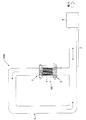
図1は、本発明の熱・音波変換ユニットおよび熱・音波変換部品の一実施形態が適用された電力発生システムの模式的な構成図である。 FIG. 1 is a schematic configuration diagram of a power generation system to which an embodiment of a heat / sonic wave conversion unit and a heat / sonic wave conversion component of the present invention is applied.
図1に示す電力発生システム1000は、熱・音波変換ユニット100、ループ管4、共鳴管5、およびエネルギー変換器6により構成されている。
A
ループ管4は、熱・音波変換ユニット100の図の上側の端部(上端部)と下側の端部(下端部)とに接続されたループ状の管である。共鳴管5は直線状の管であり、共鳴管5の一端はループ管4に接続されており、共鳴管5の他端はエネルギー変換器6に接続されている。ここで、共鳴管5とエネルギー変換器6とを合わせた全体は、実質的に図の右方向の端(不図示であるが、図のエネルギー変換器6の内部に存在する)が閉じた管となっている。
The
熱・音波変換ユニット100は、熱・音波変換部品1、高温側熱交換器2、および、低温側熱交換器3を有している。
The heat / sonic
高温側熱交換器2は、高温の加熱流体(たとえば高温の排気ガス等)の流入を受けて、その熱を図1の熱・音波変換部品1の下端部に伝達し、流入時よりも温度の下がった加熱流体を流出させるものである。一方、低温側熱交換器3は、高温側熱交換器2に流入する加熱流体に比して相対的に温度の低い冷却流体(たとえば水等)の流入を受けて、その冷熱を図1の熱・音波変換部品1の上端部に伝達し、流入時よりも温度の上がった冷却流体を流出させるものである。このような高温側熱交換器2および低温側熱交換器3の働きにより、熱・音波変換部品1の下端部が上端部よりも相対的に温度が高い状態が実現する。熱・音波変換部品1は、図の上下方向に延びる複数の細い管状の貫通孔(以下、セルと呼ぶ)を有するハニカム構造を有している。各セルは、隣接するセルから隔壁により隔てられており、高温側熱交換器2および低温側熱交換器3を介してループ管4と連通している。
The high temperature
ここで、ループ管4、共鳴管5、および熱・音波変換部品1の各セル、のそれぞれの内部は、縦波の振動を生じて音波を伝播する作動流体で満たされている。作動流体としては、たとえば、低粘性で反応性の低い希ガス等の気体を用いることができる。
Here, the inside of each of the
熱・音波変換部品1では、その両端部に上述の温度差が存在することにより、各セル内の作動流体は、各セルの貫通方向に振動を開始し、その振動は音波として熱・音波変換部品1から外部に伝播していく。このように温度差を与えると作動流体が振動する現象は、自励振動と呼ばれており、細い管に温度勾配を与えたときに起きる従来からよく知られた現象である。熱音響効果とは、熱に起因するこうした作動流体の自励振動により音波が発生することを指している。ここで、この自励振動について簡単に説明する(なお、詳細については、数多くの文献で説明されているが、たとえば、特許文献3でも詳しく説明されている)。
In the heat / sonic
細い管に温度勾配が与えられると、高温側では、細い管の内部の作動流体は、管の壁面から熱を吸収して高温側から低温側へ向けて膨張する。そして、その低温側で壁面に対し熱を放出して圧縮して元の高温側の方に戻る。このような壁面との熱の授受と膨張圧縮が繰り返されることで、結果的に、作動流体が管の延在方向に振動することとなる。簡単にいえば、この作動流体の動きは、壁の壁面の温度勾配を緩和する(弱める)ように、熱を運ぶ作動流体の動きだということができる。この説明からも明らかであるが、この現象は、管が細いために内部の作動流体に対する壁面の熱的影響が大きい場合にのみ生じるものである。このため、管を太くしていくと壁面の熱的影響が小さくなっていき(すなわち断熱状態に近づき)、こうした自励振動は生じにくくなる。そこで、自励振動により音波を発生させる上では、管の太さが重要な要素となり、この管の太さは、より定量的には、管の断面の面積をS、この断面の周長をCとしたときにHD=4×S/Cで定義される水力直径HDによって評価できる。 When a temperature gradient is applied to the thin tube, on the high temperature side, the working fluid inside the thin tube absorbs heat from the wall surface of the tube and expands from the high temperature side to the low temperature side. Then, heat is released to the wall surface at the low temperature side and compressed to return to the original high temperature side. Repeating such heat exchange with the wall surface and expansion and compression results in the working fluid oscillating in the direction in which the tube extends. Simply put, this movement of the working fluid can be said to be the movement of the working fluid that carries heat so as to moderate (weaken) the temperature gradient of the wall of the wall. As is clear from this explanation, this phenomenon occurs only when the thermal influence of the wall surface on the internal working fluid is large because the pipe is thin. For this reason, when the tube is made thicker, the thermal influence of the wall surface becomes smaller (that is, approaches a heat insulating state), and such self-excited vibration is less likely to occur. Therefore, the thickness of the tube is an important factor in generating a sound wave by self-excited vibration. The thickness of the tube is more quantitatively defined as the area of the cross section of the tube, S, and the circumference of the cross section. It can be evaluated by the hydraulic diameter HD defined by HD = 4 × S / C where C is set.
以下、図1に戻って電力発生システム1000の説明を続ける。
Hereinafter, returning to FIG. 1, the description of the
熱・音波変換部品1では細い管状のセルが複数存在し各セル内で自励振動が起きることで、それら複数のセルの作動流体の振動の集合からなる音波が、熱・音波変換部品1からループ管4に向けて発せられる。そして、その音波は、この図の点線矢印の向きにループ管4内を伝播していく。ループ管4内を伝播する音波の多くは共鳴管5内に進行し共鳴管5内を図の右方向に進行する。上述したように、共鳴管5とエネルギー変換器6とを合わせた全体は、実質的に図の右方向の端が閉じた管となっているため、反射して逆の図の左方向に進行するものも発生し、共鳴管5内では、両進行波が重ね合わされることとなる。このとき、進行波の周波数が、共鳴管5の長さ等で決まる共鳴周波数と整合すると、共鳴管5内ではいわゆる共鳴が起こり、両進行波の重ね合わせからなりその共鳴周波数を有する定在波が発生する。図では、定在波の存在が一点鎖線の両矢印で示されている。
In the heat / sonic
ここで、エネルギー変換器6では、共鳴管5の実効的な長さを変化させることができる不図示の機構が設けられており、これにより共鳴が起きるよう共鳴周波数を調整することができる。共鳴管5の実効的な長さを変化させる機構としては、たとえば、特許文献1記載のものを採用することができる。なお、ここでは、共鳴管5の実効的な長さを変化させることができるものとして説明を行うが、図1の電力発生システム1000では、熱・音波変換部品1で発生しループ管4内を進行する音波の周波数成分のうち最も支配的な周波数成分をあらかじめ把握しておき、共鳴管5の長さが、その支配的な周波数成分の周波数が共鳴周波数となるような特定の長さにあらかじめ設計されている形態が採用されてもよい。
Here, in the energy converter 6, a mechanism (not shown) that can change the effective length of the
また、エネルギー変換器6には、音波を電気信号に変換する機構も設けられている。こうした変換機構としては、たとえば、特許文献1に記載されているようなマイクロフォンを備えた機構を挙げることができる。このようにマイクロフォンを利用する変換機構が最も簡便ではあるが、マイクロフォンを利用する変換機構に限らず、音波のエネルギーを力学的なエネルギーに変換しその力学的なエネルギーを電磁誘導により電力に変換する、従来からよく知られた様々な機構(たとえば特許文献2の機構)が採用できる。
The energy converter 6 is also provided with a mechanism for converting sound waves into electrical signals. As such a conversion mechanism, for example, a mechanism including a microphone as described in
図1の電力発生システム1000では、以上説明した構成により、高温側熱交換器2に流入する高温の加熱流体(たとえば高温の排気ガス等)の熱を電力に変換することができ、エネルギーの有効利用(リサイクル)が可能となっている。
In the
次に、上記の熱・音波変換ユニット100および熱・音波変換部品1が適用された冷熱発生システムについて説明する。
Next, a cold heat generation system to which the heat / sonic
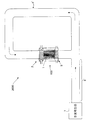
図2は、図1の熱・音波変換ユニット100および熱・音波変換部品1が適用された冷熱発生システムの模式図である。
FIG. 2 is a schematic diagram of a cold / heat generation system to which the heat / sonic
図2に示す冷熱発生システム2000は、ループ管4’、伝播管5’、音波発生部7、および、図1で説明した熱・音波変換ユニット100により構成されている。
A cold
ループ管4’は、熱・音波変換ユニット100の図2の上側の端部(上端部)と下側の端部(下端部)とに接続されたループ状の管であり、高温側熱交換器2および低温側熱交換器3を介して熱・音波変換部品1の複数のセルと連通している。伝播管5’は直線状の管であり、伝播管5’の一端はループ管4’に接続されており、伝播管5’の他端は音波発生部7に接続されている。音波発生部7は、音波を発生する機能を有しており、音波発生部7としては、たとえば、電力の供給を受けて音波を出力するスピーカを採用することができる。また、図1の電力発生システム1000からエネルギー変換器6を取り除いた、熱の供給を受けて音波を発生させるシステム(この場合、共鳴管5の右側は開放端となって反射が起きないため、図1の状況とは異なり共鳴管5内では右向きの進行波が伝播する)を採用することもできる。
The
熱・音波変換ユニット100は、その構成自体は図1で説明したものと同じであるが、図1のときとは異なり、図2の高温側熱交換器2および低温側熱交換器3の双方には、図1の低温側熱交換器3に流入したのと同様の冷却流体(たとえば水)が流入するようになっている。
The structure of the heat / sonic
ここで、ループ管4’、伝播管5’、および熱・音波変換部品1の各セルの内部は、縦波の振動を生じて音波を伝播する作動流体で満たされている。作動流体としては、たとえば、図1の電力発生システム1000と同様のものを採用できる。
Here, the inside of each cell of the
音波発生部7で発生した音波は、伝播管5’を図2の一点鎖線矢印の方向に伝播し、さらにループ管4’内を図2の点線矢印の方向に伝播していく。そして、熱・音波変換ユニット100に到達し、熱・音波変換部品1の図2の上側から各セル内に進行していく。このとき、音波による熱輸送により、高温側熱交換器2側の端部が低温側熱交換器3側の端部よりも相対的に温度が高い状態が実現する。高温側熱交換器2では常温近傍の冷却流体が流入し、常温より高い温度で流出する。一方、音波による熱輸送により熱が高温側熱交換器2側の端部へ輸送されてしまうので、熱・音波変換部品1の低温側熱交換器3側の端部は、常温より低い温度となる。低温側熱交換器3では常温近傍の冷却流体が流入し、熱・音波変換部品1の低温側熱交換器3側の端部に熱を奪われるため、常温より低い温度で流出する。言い換えれば、冷水の形で、冷熱が出力されることになる。
The sound wave generated by the sound wave generation unit 7 propagates in the
図2の冷熱発生システム2000では、以上説明した構成により、音波発生部7で発生した音波のエネルギーを用いて冷熱を出力することができる。特に、音波発生部7として、図1の電力発生システム1000からエネルギー変換器6を取り除いたシステムを採用した場合には、図1の高温側熱交換器2に流入する高温の加熱流体(たとえば高温の排気ガス等)の熱を冷熱に変換することができ、エネルギーの有効利用(リサイクル)が可能となっている。
In the cold
以上説明したように、図1の電力発生システム1000および図2の冷熱発生システム2000においては、本発明の一実施形態である熱・音波変換ユニット100がきわめて重要な役割を果たしている。以下では、図1の電力発生システム1000で使用されている状況を例にとって、熱・音波変換ユニット100について、さらに詳しく説明する。以下の説明では、一例として、図1の電力発生システム1000として、図1の高温側熱交換器2には、自動車の排気ガスの典型的な温度である400〜600℃程度の高温の加熱流体(たとえば排気ガスそのもの)が流入し、低温側熱交換器3には、20〜70℃程度の低温の冷却流体(たとえば水)が流入するものとして話を進める。この場合、熱・音波変換部品1の両端部における温度差は、330〜580℃程度となる。
As described above, in the
なお、当然のことではあるが、以下に説明する熱・音波変換ユニット100の特性そのものは、図2の冷熱発生システム2000において使用する場合も変わるものではない。
As a matter of course, the characteristics of the heat / sonic
図3は、図1の熱・音波変換ユニット100の構成を表した模式図である。
FIG. 3 is a schematic diagram illustrating the configuration of the heat / sonic
熱・音波変換ユニット100は、熱・音波変換部品1、高温側熱交換器2、および、低温側熱交換器3、金属部材32、および、干渉材1aを備えており、これら全体は、ハウジング100a内に収容されてループ管4(図1も合わせて参照)に接続されている。
The heat / sonic
熱・音波変換部品1では、それぞれが細い管状の貫通孔である複数のセル14が、隔壁11によって区画形成されてなるハニカム構造を有している。ここで、本明細書では、「セル」という語を、隔壁を含まない貫通孔のみを指すものとして用いる。各セル14は、図3の上下方向を貫通方向(各セル14が延在する延在方向)とし、低温側熱交換器3側の端面および高温側熱交換器2側の端面の両端面において開口する。熱・音波変換部品1の、低温側熱交換器3側の端面は、金属部材32と接しているとともに、金属部材32を間において低温側熱交換器3に対向している。なお、ここでは、金属部材32が配置されているが、本発明では、金属部材32が省略された形態も採用可能である。金属部材32が省略された場合には、後述のメッシュ積層体30と接触する作動流体が冷却された後に、その冷却された作動流体が、音波の振動に対応した作動流体の変位により熱・音波変換部品1の端面近傍に接触しこの端面近傍を冷却する。ここで、金属部材32が省略された形態では、熱・音波変換部品1と低温側熱交換器3との間の隙間は極力小さいことが好ましい。
The heat / sonic
金属部材32は、中央部に互いに平行な複数本のスリット(不図示)が形成された板状の金属製部材であり、図3では、その板状の側面部(厚みの部分)のみが図示されている。
The
低温側熱交換器3は、複数枚の金属製(たとえば銅製)メッシュ板を重ね合わせてなるメッシュ積層体30を有している。また、低温側熱交換器3は、メッシュ積層体30の側面を取り巻く環状の管である低温側環状管31を有している。このようにメッシュ積層体30の側面を取り巻く低温側環状管31は、図3では、流入口31aおよび流出口31bを含む断面においてメッシュ積層体30の両側を挟み込むものとして模式的に示されている。この低温側環状管31は、流入口31aから、後述する高温側熱交換器2に流入する加熱流体よりは相対的に低温の冷却流体(たとえば水)の流入を受け、その冷却流体の冷熱をメッシュ積層体30に伝達し(逆の言い方をすればメッシュ積層体30の熱を冷却流体に伝達し)、流出口31bから、温度が上昇した冷却流体を流出させる役割を果たしている。
The low temperature
メッシュ積層体30に伝達された冷熱は、接触している作動流体に伝わり、さらに音波の変位で熱・音波変換部品1の、低温側熱交換器3側の端面に伝達され、熱・音波変換部品1の低温側熱交換器3側の端部を冷却する。このため、金属部材32の材質としては熱伝導率の高いものが好ましく、たとえば、銅製のものを用いることができる。
The cold heat transmitted to the
なお、以上では、低温側熱交換器3の構成について詳しく説明したが、本発明の熱・音波変換ユニットは、低温側の熱交換器の詳細に特に限定されず、従来から知られている熱交換器を採用してもよい。また、後述する高温側熱交換器2と同じ構成のものを採用してもよい。
In addition, although the structure of the low temperature
熱・音波変換部品1の側面は、干渉材1aによって取り巻かれており、図3の模式的な断面図では、その取り巻く干渉材1aが、熱・音波変換部品1を図の左右両側から挟み込む2つに分かれた干渉材1aとして示されている。この干渉材1aは、熱・音波変換部品1の、低温側熱交換器3側の端部と高温側熱交換器2側の端部との間で熱・音波変換部品1外部の周囲環境を介して熱の伝達が行われるのを防ぐ断熱材としての役割を果たしている。
The side surface of the heat / sonic
高温側熱交換器2は、熱交換ハニカム構造体20および高温側環状管21を備えている。熱交換ハニカム構造体20は、熱・音波変換部品1と同様にハニカム構造を有しており、それぞれが図3の上下方向を貫通する細い管状の貫通孔である2以上のセル20dが、隔壁20aによって区画形成されている。高温側環状管21は、熱交換ハニカム構造体20の側面を取り巻く環状の管であり、流入口21aから高温の加熱流体(たとえば、高温の排気ガス)の流入を受けてその加熱流体の熱を熱交換ハニカム構造体20に伝達し流出口21bから温度が低下した加熱流体を流出させる役割を果たす。ここで、図3に示すように、高温側環状管21の管内には、加熱流体との接触面積を増加させるために、金属製あるいはSiC(炭化珪素)を主成分とするセラミックス製のフィン21eが設けられている。
The high temperature
図4は、図3の熱・音波変換ユニット100における高温側熱交換器2の外観斜視図であり、図5は、高温側環状管21の流入口21aおよび流出口21bを含む平面で見たときの高温側熱交換器2の断面図である。
4 is an external perspective view of the high temperature
図4に示すように、高温側熱交換器2では、高温側環状管21の環状形状における中央の空洞部分に熱交換ハニカム構造体20が嵌め込まれた構成となっている。この高温側環状管21には、図4の太い矢印で示すように、図の下側の流入口21aから高温の加熱流体(たとえば、高温の排気ガス)が流入し、図の上側の流出口21bから流出する。このとき、流入口21aから流入した高温の加熱流体は、図5の矢印で示すように、熱交換ハニカム構造体20の円形の外周を構成する外周壁20bに直接に突き当たり、外周壁20bの左右二手に分かれて外周壁20bに沿って進み、流出口21bで合流して流出する。このように熱交換ハニカム構造体20の外周壁20bに対して直接に高温の加熱流体が接触することで、高温の加熱流体から外周壁20bに対して多量の熱が直接に伝達され、その熱は、熱交換ハニカム構造体20内部の隔壁20aやセル20d内部の作動流体にも伝達される。このように、熱交換ハニカム構造体20が高温の加熱流体に直接に接触できるのは、後述するように、熱交換ハニカム構造体20が、耐熱性および熱伝導性が高い材料で構成されているためであり、直接に加熱流体と接触できることで、間に他の部材を介した場合と比べ、熱の損失を抑え熱交換効率の向上が図られる。
As shown in FIG. 4, the high temperature
なお、このように熱交換ハニカム構造体20が直接に加熱流体と接触する形態が好ましいが、本発明では、熱交換ハニカム構造体20の外周壁20bが高温の加熱流体に直接に接触する代わりに、外周壁20bの周囲を金属で覆う形態も採用することができる。特に、音波を伝播する作動流体として高圧の気体(たとえばアルゴン等の不活性の希ガス)を用いる場合には、こうした高圧の気体を密閉して漏れを防ぐ観点からこのように外周壁20bの周囲を金属で覆う形態が好ましい。この場合、外周壁20bの周囲を覆った金属の外周面に、図5の熱交換ハニカム構造体20の中心からみて外向き方向(動径方向)に突出した金属製のフィン(たとえば図3のフィン21e参照)を備えていることが好ましい。これは、高温の加熱流体との接触面積を増加させて熱交換効率を高めるためである。高温の加熱流体との接触面積が小さいと、高温の加熱流体と高温側熱交換器2との熱の授受が不十分で高温側熱交換器2の熱交換効率が低下してしまうので、高温加熱流体との接触面積をできるだけ大きくすることが高温側熱交換器2にとって重要となる。
It is preferable that the heat
特に、SiC(炭化珪素)を主成分とするセラミックス材料で構成された、さらに別のハニカム構造体が高温側環状管の管内に嵌合している形態が最も好ましい。これは、SiC(炭化珪素)を主成分とするセラミックス材料は、金属製のフィンより高温での熱伝導率が高く、高温ガスとの接触面積も飛躍的に増加させることができ、さらに、金属製のフィンでは問題となり得る高温の加熱流体による腐食劣化の問題も回避できるからである。以下、この好ましい形態について説明する。 In particular, a configuration in which another honeycomb structure made of a ceramic material containing SiC (silicon carbide) as a main component is fitted in the pipe of the high temperature side annular pipe is most preferable. This is because a ceramic material mainly composed of SiC (silicon carbide) has a higher thermal conductivity at a higher temperature than metal fins, and can dramatically increase the contact area with a high-temperature gas. This is because it is possible to avoid the problem of corrosion deterioration due to the high-temperature heating fluid, which can be a problem with fins made of metal. Hereinafter, this preferable form is demonstrated.
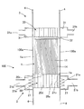
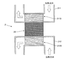
図6は、高温側環状管の管内にさらに別のハニカム構造体が嵌合している熱・音波変換ユニットの一形態を表す模式図であり、図7は、図6のA−A線の断面における高温側熱交換器の模式的な断面構成図である。 FIG. 6 is a schematic diagram showing an embodiment of a heat / sonic wave conversion unit in which another honeycomb structure is fitted in the tube of the high temperature side annular tube, and FIG. 7 is a diagram of line AA in FIG. It is a typical section lineblock diagram of a high temperature side heat exchanger in a section.
図6および図7では、図3〜図5と同一の構成要素については同一の符号を付し、その重複説明は省略する。 In FIG. 6 and FIG. 7, the same code | symbol is attached | subjected about the same component as FIGS. 3-5, and the duplication description is abbreviate | omitted.
図6の熱・音波変換ユニット200における高温側熱交換器2’は、熱交換ハニカム構造体20’および2つの互いに異なる高温側環状管211,212を有している。熱交換ハニカム構造体20’は、図中の水平方向を貫通方向とする2以上のセルが隔壁により区画形成されたハニカム構造を有しており、2つの異なる高温側環状管211,212により加熱流体から伝達された熱を熱・音波変換部品1に伝達する。ここで、熱交換ハニカム構造体20’は、熱・音波変換部品1から間隔tを置いて配置されている。
The high temperature
図7に示すように、2つの高温側環状管211,212の内部には、SiC(炭化珪素)を主成分とするセラミックス材料で構成された管内ハニカム構造体2110,2120がそれぞれ備えられている。管内ハニカム構造体2110,2120は、いずれも図中の水平方向を貫通方向とする2以上のセルが隔壁により区画形成されたハニカム構造を有している。2つの高温側環状管211,212では、図の矢印で示すように、流入した加熱流体が管内ハニカム構造体2110,2120の各セルを通過して流出していく。このとき、各セルを通過する加熱流体の熱が管内ハニカム構造体2110,2120に伝わり、その熱は、高温側環状管211,212の壁面、および、熱交換ハニカム構造体20’の側面(外周壁の面)を取り巻く金属管(不図示)を介して、熱交換ハニカム構造体20’に伝達される。なお、図7では、説明の簡単化のため、熱交換ハニカム構造体20’の断面が矩形形状で図示されているが、図4および図5のように断面が円形状の場合であっても、高温側環状管211,212の形状を円形に沿うようにする等により実質的に同様の構成を取り得る。
As shown in FIG. 7, in-
このように熱交換ハニカム構造体20’の外周壁を金属管で覆い、その外側に、SiC(炭化珪素)を主成分とするセラミックス材料で構成された2つの管内ハニカム構造体2110,2120を配置する構造では、熱交換ハニカム構造体20’は直接加熱流体と接触せず、このため、高温の加熱流体による腐食劣化を抑えることができる。また、作動流体として不活性な希ガス(たとえばアルゴン等)を用いる場合には、作動流体により熱交換ハニカム構造体20’が腐食する問題も生じない。この場合、熱交換ハニカム構造体20’の材料としては、SiC(炭化珪素)を主成分とするセラミックス材料の他、熱伝導性の高い金属材料、たとえば銅も採用できる。
In this way, the outer peripheral wall of the heat
ここで、図6における熱交換ハニカム構造体20’の長さL’は、作動流体の振動によって発生する音波の波長程度であることが好ましい。音波の波長よりも長すぎると作動流体(たとえば不活性な希ガス)への熱の供与が不十分となる。一方、長さL’が音波の波長よりも短すぎると、外側から熱交換ハニカム構造体20’を通り抜けて熱・音波変換部品1へ達してしまい、比較的低温の作動流体が熱・音波変換部品1の高温熱交換器側の端部を冷やしてしまうといった悪影響が生じ得る。
Here, the length L ′ of the heat
図8は、図6および図7に示す熱・音波変換ユニットとは別の本発明の熱・音波変換ユニットの一形態を表す模式図、図9は、図8に示す熱・音波変換ユニットとはさらに別の熱・音波変換ユニットの一形態を表す模式図である。 FIG. 8 is a schematic diagram showing an embodiment of the thermal / sonic wave conversion unit of the present invention different from the thermal / sonic wave conversion unit shown in FIGS. 6 and 7, and FIG. 9 shows the thermal / sonic wave conversion unit shown in FIG. FIG. 5 is a schematic diagram showing another embodiment of another heat / sonic wave conversion unit.
図8に示す熱・音波変換ユニットでは、高温側熱交換器2Aにおいて、図中の上側から加熱流体が流入し高温側熱交換器2Aの内部を通って図中の下方向に向けて流出する。一方、図9に示す熱・音波変換ユニットでは、高温側熱交換器2A’において、図中の上側から加熱流体が流入し高温側熱交換器2A’の内部を通って図中の上方向に向けて流出する。ここで、図8および図9に示す熱・音波変換ユニットのいずれも、低温側熱交換器3Aにおいては、図中の上側から冷却流体が流入し低温側熱交換器3Aの内部を通って図中の上方向に向けて流出する。ここで、図8および図9では、内部構造(以下の2つのハニカム構造体22,23を含む構造)を明らかにするために、一部については透視図となっている。
In the heat / sonic wave conversion unit shown in FIG. 8, in the high temperature
図8の高温側熱交換器2Aおよび図9の高温側熱交換器2A’は、金属材料で構成された柱状のハニカム構造体23と、その周りを取り囲む、SiC(炭化珪素)を主成分とするセラミックス材料で構成された中空の円柱状(言い換えれば厚みのある円筒状)のハニカム構造体22とを有している。ハニカム構造体23の外周では同一の金属材料の後述の金属メッシュ外筒23aが金属製のハニカム構造体23と一体に形成されている。なお、正確には、2つのハニカム構造体22,23の間にはメタライズ層が存在するが、これについては後述する。これら2つのハニカム構造体22,23は、いずれも、円柱状の形状の延在方向を貫通方向とする2以上のセルが隔壁により区画形成されたハニカム構造を有している。このような図8および図9の構造によっても、熱の損失を抑え熱交換効率の向上が図られる。
The high temperature
なお、ここでは、金属材料で構成されたハニカム構造体23によるハニカム構造が採用されているが、これに代えて金属製のメッシュで構成されたメッシュ構造が採用されてもよい。
Here, although a honeycomb structure by the
図10は、メッシュ構造を採用した高温側熱交換器の断面図である。 FIG. 10 is a cross-sectional view of a high temperature side heat exchanger employing a mesh structure.
図10に示す高温側熱交換器では、金属外筒22aで外周が囲まれた、SiC(炭化珪素)を主成分とするセラミックス材料で構成されたハニカム構造体22のさらなる内側に、円筒状のメタライズ層23bおよび金属メッシュ外筒23aを介して金属メッシュ体23’が備えられている。ここで、メタライズ層23bは、モリブデンやマンガン等の金属の焼き付けによって形成された層であり、金属製の金属メッシュ外筒23aとセラミックス製のハニカム構造体22を接合させるための層である。図10に示す構造によっても、熱の損失を抑え熱交換効率の向上が図られる。
In the high temperature side heat exchanger shown in FIG. 10, a cylindrical shape is formed on the further inner side of the
以下、再び、図3〜図5に戻って説明を続ける。 Hereinafter, the description will be continued by returning to FIGS.
図3に示すように、熱交換ハニカム構造体20の、熱・音波変換部品1側の端面(熱交換ハニカム構造体20の上側の端面)は、熱・音波変換部品1の、高温側熱交換器2側の端面(熱・音波変換部品1の下側の端面)と直接に接触している。以下、この熱交換ハニカム構造体20の上側の端面を接触面20sと呼ぶ。なお、本発明では、このように熱・音波変換部品1と熱交換ハニカム構造体20とが直接に接触する代わりに、熱・音波変換部品1と熱交換ハニカム構造体20との間に図6の間隔tのような隙間が存在していてもよい。この場合、熱交換ハニカム構造体20に対して伝達された熱は、熱交換ハニカム構造体20と接した作動流体に伝達され、その加熱された作動流体が、音波の振動に対応した作動流体の変位により熱・音波変換部品1の端面近傍に接触し、この端面近傍が加熱される。これにより、熱・音波変換部品1の、高温側熱交換器2側の端部は、低温側熱交換器3側の端部に比して相対的に温度の高い状態に維持されることとなる。
As shown in FIG. 3, the end surface on the heat / sonic
ここで、この熱交換ハニカム構造体20は、SiC(炭化珪素)を主成分とするセラミックス材料で構成されている。セラミックス材料は、耐熱性が高いため、上述のように直接に高温の加熱流体に接触する熱交換ハニカム構造体20の材料に適している。さらに、セラミックス材料の中でもSiCを主成分とするセラミックス材料は、熱伝導率が相対的に高いため、上述したように熱交換ハニカム構造体20が熱・音波変換部品1に熱を伝達する役割を果たすのに適した材料となっている。ここで、「SiCを主成分とする」とは、SiCが、熱交換ハニカム構造体20の材料の50質量%以上を占めることを意味する。このときの気孔率としては、0〜10%であることが好ましい。また、隔壁20aの厚さが0.25〜0.51mmであってセル密度が15〜62セル/cm2であることが好ましい。
Here, the heat
SiCを主成分とするセラミックス材料としては、具体的には、単純なSiCに加え、Si含浸SiC、(Si+Al)含浸SiC、金属複合SiC、再結晶SiC、Si3N4、及びSiC等を採用することができる。これらの中でも、Si含浸SiC、(Si+Al)含浸SiCが好ましい。その理由は、Siを含浸するSiCは、高い熱伝導率および耐熱性を有することに加え、多孔質体であっても気孔率が低く緻密に形成されているため、Siを含浸しないSiCに比して相対的に高い強度を実現できるからである。 Specifically, as a ceramic material mainly composed of SiC, in addition to simple SiC, Si-impregnated SiC, (Si + Al) -impregnated SiC, metal composite SiC, recrystallized SiC, Si 3 N 4 , SiC and the like are employed. can do. Among these, Si-impregnated SiC and (Si + Al) -impregnated SiC are preferable. The reason for this is that SiC impregnated with Si has high thermal conductivity and heat resistance, and even if it is a porous body, it has a low porosity and is densely formed. This is because relatively high strength can be realized.
ここで、熱交換ハニカム構造体20では、図5に示すように三角形のセル20dが、セル20dの貫通方向に垂直な面内で、決まった長さの周期で周期的に配列した構成が採用されている。後述するように、熱の伝達先である熱・音波変換部品1においても同様の構成が採用されており(後述の図11参照)、熱交換ハニカム構造体20におけるセル20dのこの周期は、熱・音波変換部品1におけるセル14の周期(後述の図11参照)の10以上の整数倍となっている。このように、熱交換ハニカム構造体20のセル20dの形状として、熱の伝達先である熱・音波変換部品1のセル14の形状と同一の形状を採用し、熱交換ハニカム構造体20のセル20dの周期として、熱・音波変換部品1のセル14の周期の整数倍のものを採用することで、熱交換ハニカム構造体20のセル20dの内部、および、熱・音波変換部品1のセル14の内部を満たしている作動流体の動きがスムーズになるよう工夫されている。なお、熱交換ハニカム構造体20のセルの周期が、熱・音波変換部品1のセルの周期よりも大きい理由は、熱・音波変換部品1のセル14は、上述した自励振動を起こすためにきわめて細い貫通孔であることが要求されるためである。熱交換ハニカム構造体20のセル20dには、そうした要請はなく、熱交換ハニカム構造体20は熱交換の役割を果たせば十分であるため、熱・音波変換部品1のセル14の周期に比べ、1桁(10倍)以上の大きさのものとなっている。
Here, in the heat
また、図3に示すように、熱交換ハニカム構造体20では、熱・音波変換部品1との接触面20sは、熱交換ハニカム構造体20が高温の加熱流体と直接に接触して熱を受ける受熱領域21cよりも、熱・音波変換部品1側(図の上方向)にずれた位置にあり、受熱領域21cと重ならないようになっている。仮に、接触面20sが受熱領域21cと重なってしまうと、接触面20sのうち、受熱領域21cに近い縁の周辺と、受熱領域21cから遠い中央付近とでは、温度差が大きく異なる状態が生じることがある。この場合、熱・音波変換部品1の、熱交換ハニカム構造体20側の端部(図3の下端部)が均一に加熱されないために、熱・音波変換部品1の各セルの自励振動が各セルに応じてムラが出るという問題が生じ得る。図3の熱交換ハニカム構造体20では、接触面20sが受熱領域21cと重ならないようになっていることで、こうした問題を回避している。
In addition, as shown in FIG. 3, in the heat
また、図5に示すように、熱交換ハニカム構造体20では、外周壁20bの一部が欠けてセル20dの貫通方向に沿って延びるスリット20cが形成されている。図5では、例として、熱交換ハニカム構造体20の外周面の4か所にスリット20cが形成された例が示されている。こうしたスリット20cが存在することで、高温の加熱流体が直接に外周壁20bに接触したときに、外周壁20bに生じる熱応力を緩和することができ、この結果、外周壁20bや隔壁20aの割れや剥離を抑えることができる。
Further, as shown in FIG. 5, in the heat
また、図5に示すように、高温側環状管21には、スリット20cが延在する方向に沿って、各スリット20cによる空隙を塞ぎつつ延在する4つの耐熱性金属板21dが設けられている。これら4つの耐熱性金属板21dにより、4つのスリット20cから作動流体が高温側環状管21内に漏れ出すことが防がれる。ここで、熱交換ハニカム構造体20は、高温側環状管21の環状の中央部で、これら4つの耐熱性金属板21dに嵌め込まれることで支持される。また、4つの耐熱性金属板21dにおいて、図5の熱交換ハニカム構造体20の中心からみて外向き方向(動径方向)に突出した金属製あるいはSiC(炭化珪素)を主成分とするセラミックス製のフィン21e(図3も合わせて参照)が備えられている。
As shown in FIG. 5, the high temperature side
次に、図3に示す熱・音波変換部品1について詳しく説明する。
Next, the heat / sonic
図11は、図3に示す熱・音波変換部品1のセル14の貫通方向に垂直な面内における熱・音波変換部品1の断面図である。
11 is a cross-sectional view of the heat / sonic
図11に示すように、熱・音波変換部品1は、それぞれが細い管状の貫通孔である複数のセル14が、隔壁11によって区画形成され、さらにそれら隔壁11の全体の外周を外周壁13で取り囲むことで形成されている。ここで、外周壁13の構成材料としては、隔壁11の構成材料と同じものを採用できる。
As shown in FIG. 11, in the heat / sonic
上述したように、自励振動により音波を発生させる上でセル14の水力直径HDが1つの重要な要素であり、熱・音波変換部品1のセル14の水力直径HDは0.4mm以下のきわめて小さい値となっている。このような水力直径HDがきわめて小さいセルが形成されていることで、熱・音波変換部品1では、十分な熱音響効果を得ることができる。逆に、水力直径HDが0.4mmより大きい場合、きわめて小さい熱音響効果しか得られず、たとえば、図1の電力発生システム1000や図2の冷熱発生システム2000で十分な量の電力や冷熱を得ることは難しくなる。
As described above, the hydraulic diameter HD of the
ここで、より大きな熱音響効果を発揮するには、上述の水力直径HDが小さいセルを、できるだけ数多く形成するのが有利である。言い換えれば、熱・音波変換部品1の端面における開口率が大きい方が有利である。熱・音波変換部品1は、各端面において60%以上の高い開口率を有しており、これにより大きな熱音響効果を発揮することができる。逆に60%未満の開口率では、熱音響効果に寄与するセルが少なすぎてあまり大きな熱音響効果は得られない。
Here, in order to exert a greater thermoacoustic effect, it is advantageous to form as many cells as possible with the aforementioned small hydraulic diameter HD. In other words, it is advantageous that the aperture ratio at the end face of the heat / sonic
ただし、開口率が高すぎると、熱・音波変換部品1の空洞部分が多すぎることとなり、熱・音波変換部品1全体の耐久性や強度が低下する。そこで、熱・音波変換部品1では開口率は93%以下に抑えられている。実際、開口率が93%を超えると、発生した音波による衝撃や熱・音波変換部品1の両端の温度差に起因する熱的な歪みやねじれ(熱応力)により生じる熱・音波変換部品1の損傷が無視できなくなる。
However, when the aperture ratio is too high, there are too many hollow portions of the heat / sonic
まとめると、熱・音波変換部品1では、熱・音波変換部品1の端面における開口率が60%以上93%以下となることで、十分な熱音響効果の発揮と十分な耐久性・強度との適度なバランスが実現している。なお、60%以上93%以下の開口率の中でも、80%以上93%以下の開口率が好ましい。
In summary, in the heat / sonic
なお、上記開口率は、貫通方向に垂直な断面を顕微鏡で撮影し、このときの断面の撮影画像から、材料部分面積S1と空隙部分面積S2を求め、S1とS2を用いてS2/(S1+S2)として求められる。 The aperture ratio is obtained by taking a cross section perpendicular to the penetrating direction with a microscope, obtaining a material partial area S1 and a void partial area S2 from a photographed image of the cross section at this time, and using S1 and S2, S2 / (S1 + S2 ).
また、熱・音波変換部品1では、セル14の貫通方向に沿った単位長さ当たりの熱容量は、この貫通方向に沿って図3の低温側熱交換器3側の端面(図3の熱・音波変換部品1の上側の端面)から離れるほど減少する傾向を示す。
Further, in the heat / sonic
ここで、上記の「単位長さ」は、熱・音波変換部品1の長さを評価する上で長さの基準単位となる長さを指しており、熱・音波変換部品1よりも短い長さである限り適宜選択することが可能である。たとえば、数cm〜数百cm程度の長さの熱・音波変換部品1に対しては、上記の「単位長さ」として10mm(1cm)を採用することができる。
Here, the above-mentioned “unit length” refers to a length that is a reference unit of length in evaluating the length of the heat / sonic
また、上記の「減少する傾向」には、単調に減少する場合の他に、部分的には増減せずに一定となることもあるが全体的には減少する場合も含まれている。数学的に表現すれば、上記の「減少する傾向を示す」は、低温側熱交換器3側の端面(図3の熱・音波変換部品1の上側の端面)からの距離を変数とし、上記貫通方向に沿った単位長さ当たりの熱容量をこの変数によって値が決定される関数とすると、この関数の傾きの値(変数による微分値)が、常に、ゼロまたは負の値となり、正の値には常にならないことを意味する。
In addition to the case of a monotonous decrease, the above “decrease tendency” also includes a case where it does not increase or decrease partially but becomes constant but decreases as a whole. Expressed mathematically, the above-mentioned “showing a tendency to decrease” means that the distance from the end surface on the low temperature
さらに、図3の熱・音波変換部品1では、低温側熱交換器3側の端面(図3の熱・音波変換部品1の上側の端面)を含む端部であってセル14の貫通方向に沿った熱・音波変換部品1の全長の10%の領域を占める端部の熱容量は、高温側熱交換器2側の端面(図3の熱・音波変換部品1の下側の端面)を含む端部であってセル14の貫通方向に沿った熱・音波変換部品1の全長の10%の領域を占める端部の熱容量の1.1倍以上となっている。以下では、前者の端部(低温側熱交換器3側の端面を含む端部)を第1端部と呼び、後者の端部(高温側熱交換器2側の端面を含む端部)を第2端部と呼ぶ。
Further, in the heat / sonic
ここで、単位長さ当たりの熱容量は、以下のようにして求められる。まず、測定したい単位長さの部位を切り出し、それを粉砕して粉末状にする。その粉末状のものをサンプルとして、そのサンプルについて断熱型熱量計を用いて投入熱と温度上昇の関係を調べる。これにより、そのサンプルの単位質量当たりの熱容量を求めることができる。そして、サンプルとして用いた粉砕前の測定対象の部位の質量を、その求めた単位質量当たりの熱容量に乗じることで、単位長さ当たりの熱容量を得ることができる。なお、その単位長さの方向に垂直な面におけるその部位の断面の面積で上記の単位長さ当たりの熱容量を除算すれば、この部位の単位体積当たりの熱容量を得ることもできる。 Here, the heat capacity per unit length is obtained as follows. First, a unit length portion to be measured is cut out and pulverized into a powder. Using the powdery material as a sample, the relationship between the input heat and the temperature rise is examined for the sample using an adiabatic calorimeter. Thereby, the heat capacity per unit mass of the sample can be obtained. Then, the heat capacity per unit length can be obtained by multiplying the mass of the part to be measured used as a sample before the pulverization by the obtained heat capacity per unit mass. If the heat capacity per unit length is divided by the area of the cross section of the part in a plane perpendicular to the unit length direction, the heat capacity per unit volume of the part can be obtained.
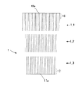
図12は、熱・音波変換部品1における第1端部および第2端部を説明するための概念図である。
FIG. 12 is a conceptual diagram for explaining the first end and the second end of the heat / sonic
図12に示すように、熱・音波変換部品1の上側の端部である第1端部16は、熱・音波変換部品1の全長Lの10%の領域、すなわち、熱・音波変換部品1の上側の端面(第1の端面16a)から(1/10)Lの長さの領域を占める端部である。一方、熱・音波変換部品1の下側の端部である第2端部17は、熱・音波変換部品1の全長Lの10%の領域、すなわち、熱・音波変換部品1の下側の端面(第2の端面16b)から(1/10)Lの長さの領域を占める端部である。第1端部16の熱容量は、第2端部17の熱容量より大きく、上述したように第2端部17の熱容量の1.1倍以上となっている。また、第1端部16と第2端部17の間においては、セル14の貫通方向に沿った単位長さ当たりの熱容量は、上述したように、この貫通方向に沿って図12の上側の端面(図3の低温側熱交換器3側の端面)から離れるほど減少する傾向を示す。以下、このようにセル14の貫通方向に沿って単位長さ当たりの熱容量に勾配を持たせる理由について説明する。
As shown in FIG. 12, the
図1の説明において上述したように、熱音響効果の原因となる自励振動は、温度勾配を緩和する(弱める)ように熱を運ぶ作動流体の動きである。図12の熱・音波変換部品1でいえば、セル14内の作動流体は、第1端部16側と第2端部17側との間の温度勾配を緩和するように自励振動を起こす。たとえば、瞬間的に、第1端部16に対しある量の温熱が与えられ第2端部17に対しある量の冷熱が与えられた(つまり、ある量の熱が第2端部17から吸収された)場合、作動流体が自励振動を起こすことにより、上述の温熱と冷熱の供給によって生じた第1端部16側と第2端部17側との間の温度勾配は、時間の経過とともに徐々に緩和されていくことになる。
As described above in the description of FIG. 1, the self-excited vibration that causes the thermoacoustic effect is the movement of the working fluid that carries heat so as to relax (weaken) the temperature gradient. In the heat / sonic
ここで、仮に、熱・音波変換部品1において、セル14の貫通方向に沿った単位長さ当たりの熱容量がこの貫通方向に沿って一様であるとすると、温度勾配が緩和されて、その単位長さ当たりの熱容量に応じた一定の温度に達する。一方、実際の熱・音波変換部品1のように、セル14の貫通方向に沿った単位長さ当たりの熱容量が、この貫通方向に沿って図12の上側の端面(図3の低温側熱交換器3側の端面)から離れるほど減少する構成では、もちろん最終的には全体で一定の温度に到達するものの、途中の段階では、単位長さ当たりの熱容量にばらつきがあることに起因して局所的に温度勾配の緩和の仕方が異なることとなり、全体的に温度勾配が残りやすい。言い換えれば、単位長さ当たりの熱容量にばらつきがある場合の方が、単位長さ当たりの熱容量が一様な場合に比べて、温度勾配の緩和に時間がかかることになる。すなわち、単位長さ当たりの熱容量にばらつきを持たせることで、温度勾配が維持されやすいことになる。特に、第1端部16の熱容量が第2端部17の熱容量の1.1倍以上となっていると、この温度勾配が維持される効果が十分に大きく、高い熱・音波変換機能の発揮が可能となる。この点については、後述の実施例によって検証する。
Here, in the heat / sonic
ここで、セル14の貫通方向に沿った単位長さ当たりの熱容量に変化を持たせるには、以下に説明する、セル14の貫通方向に沿った単位長さ当たりの熱容量が互いに異なる複数のハニカムセグメントを用いるのが簡便である。
Here, in order to change the heat capacity per unit length along the penetration direction of the
これら複数のハニカムセグメントはいずれも、ハニカム構造(2つの端面の間を貫通する複数のセルが隔壁によって区画形成されている構造)を備えており一体的に形成されたものである。ここで、このハニカム構造では、各セルの水力直径HDが0.4mm以下であって、かつ、各端面の開口率が60%以上93%以下となっており、熱・音波変換機能を発揮することができる。また、複数のハニカムセグメントのうち、セル14の貫通方向に沿った単位長さ当たりの熱容量が最も大きいハニカムセグメント(以下、第1のハニカムセグメントと呼ぶ)のその単位長さ当たりの熱容量は、セル14の貫通方向に沿った単位長さ当たりの熱容量が最も小さいハニカムセグメント(以下、第2のハニカムセグメントと呼ぶ)のその単位長さ当たりの熱容量の1.1倍以上である。ここで、第1のハニカムセグメントおよび第2のハニカムセグメントはいずれも、全長(各ハニカムセグメントの各セルの貫通方向に沿った長さ)が、上記の複数のハニカムセグメントの全長の総和の1/10倍以上となっている。第1のハニカムセグメントおよび第2のハニカムセグメントの長さについてこのような条件が課される点を除き、複数のハニカムセグメントそれぞれの長さは特に限定されず、互いに同じであってもよいし、互いに異なっていてもよい。あるいは、複数のハニカムセグメントのうちの一群のハニカムセグメントの長さは同一であって、残りのハニカムセグメントの長さが互いに異なるものであってもよい。 Each of the plurality of honeycomb segments has a honeycomb structure (a structure in which a plurality of cells penetrating between two end faces are partitioned by partition walls) and is integrally formed. Here, in this honeycomb structure, the hydraulic diameter HD of each cell is 0.4 mm or less, and the opening ratio of each end face is 60% or more and 93% or less, and exhibits a heat / sonic wave conversion function. be able to. In addition, among the plurality of honeycomb segments, the heat capacity per unit length of the honeycomb segment having the largest heat capacity per unit length along the penetration direction of the cell 14 (hereinafter referred to as the first honeycomb segment) The heat capacity per unit length along the 14 penetration directions is 1.1 times or more the heat capacity per unit length of the smallest honeycomb segment (hereinafter referred to as the second honeycomb segment). Here, in each of the first honeycomb segment and the second honeycomb segment, the total length (the length along the penetration direction of each cell of each honeycomb segment) is 1 / of the total length of the plurality of honeycomb segments. 10 times or more. Except that such conditions are imposed on the lengths of the first honeycomb segment and the second honeycomb segment, the length of each of the plurality of honeycomb segments is not particularly limited and may be the same as each other. They may be different from each other. Alternatively, a group of honeycomb segments among the plurality of honeycomb segments may have the same length, and the remaining honeycomb segments may have different lengths.
これら複数のハニカムセグメントが、各ハニカムセグメントの一端面が前記複数のハニカムセグメントのうちの別のハニカムセグメントの一端面に対向した状態で、セル14の貫通方向に沿った単位長さ当たりの熱容量の大きい順に直列的に配置されることで、上述の熱・音波変換部品1の一例が実現する。この例では、第1のハニカムセグメントは、熱・音波変換部品1の上述の第1端部16(図12参照)を含むものであり、第2のハニカムセグメントは、熱・音波変換部品1の上述の第2端部17(図12参照)を含むものである。
The plurality of honeycomb segments have a heat capacity per unit length along the penetration direction of the
ここで、複数のハニカムセグメントが直列的に配置される際には、互いに隣接する2つのハニカムセグメントの間で、互いに対向する端面における各セルの開口同士が重なり合って1つの貫通孔(言い換えれば、2つのセルがつながることで形成された1つのセル)が形成されるように、複数のハニカムセグメントが配置されることが好ましい。このとき、上述のように各セルの開口同士が重なり合った状態を維持しつつ、互いに隣接する2つのハニカムセグメントの互いに対向する端面同士を接合材で接着する形態が採用されてもよい。なお、この場合、接合材によって形成された、隣接ハニカムセグメント間の接合層は、厳密に言えば、熱・音波変換部品1の上述の「単位長さ当たりの熱容量」に寄与するが、通常、接合層は薄いため、その寄与は十分に小さい。このため、間に接合層を介して、単位長さ当たりの熱容量の大きい順に並んだ複数のハニカムセグメントの直列的な配置により、上述した、単位長さ当たりの熱容量が一方の端面(図3の低温側熱交換器3側の端面)から離れるほど減少する傾向を示すという熱・音波変換部品1の特徴は十分に実現可能である。ただし、この場合の「単位長さ」は、接合層の厚さよりも十分に大きい長さである。たとえば、10mm(1cm)の単位長さであれば、こうした条件を十分に満たすことができる。
Here, when the plurality of honeycomb segments are arranged in series, between the two adjacent honeycomb segments, the openings of the cells on the end faces facing each other overlap each other to form one through hole (in other words, It is preferable that a plurality of honeycomb segments are arranged so that a single cell formed by connecting two cells is formed. At this time, the form which adhere | attaches the mutually opposing end surfaces of two adjacent honeycomb segments with a joining material may be employ | adopted, maintaining the state where opening of each cell overlapped as mentioned above. In this case, the bonding layer formed between the adjacent honeycomb segments formed by the bonding material contributes to the above-mentioned “heat capacity per unit length” of the heat / sonic
また、接合材で端面同士を接着するのに代えて、各セルの開口同士が重なり合った密着状態で配置された複数のハニカムセグメント全体を、この密着状態のまま、筒状の収容部材の内部に嵌め込むことで、収容部材の内部において各ハニカムセグメントを位置決めして固定する形態が採用されてもよい。 Further, instead of adhering the end surfaces to each other with a bonding material, the entire plurality of honeycomb segments arranged in a close contact state in which the openings of each cell overlap each other are kept in this close contact state inside the cylindrical housing member. A form in which each honeycomb segment is positioned and fixed inside the accommodating member by fitting may be adopted.
さらには、このように密着状態で位置決めして固定する代わりに、音波の伝達に支障が生じない程度の微小な間隙を置いて複数のハニカムセグメントが、単位長さ当たりの熱容量の大きい順に筒状の収容部材の内部に嵌め込まれて位置決めおよび固定されるものであってもよい。 Furthermore, instead of positioning and fixing in close contact in this way, a plurality of honeycomb segments are arranged in the order of increasing heat capacity per unit length with a minute gap that does not hinder the transmission of sound waves. It may be fitted and positioned and fixed inside the housing member.
以下では、3つのハニカムセグメントで構成された熱・音波変換部品1を例にとってさらに具体的に説明する。
Hereinafter, the heat / sonic
図13は、円相当直径が同一で単位体積当たりの熱容量が互いに異なる3つのハニカムセグメントからなる熱・音波変換部品1の構成を表す模式図である。
FIG. 13 is a schematic diagram showing the configuration of the heat / sonic
なお、図13では、熱・音波変換部品1が3つのハニカムセグメントで構成されていることを明確にするために、ハニカムセグメント間に、ある程度の距離を設けて熱・音波変換部品1の構成が模式的に図示されているが、実際には、隣接するハニカムセグメントは、上述したように、接合材で接合されているか、または、筒状の収容部材の内部に、密着状態あるいは微小な間隙を置いて嵌め込まれて位置決めされた構成が実現している。このような構成では、互いに対向する端面における各セルの開口同士が、互いに重なり合うか、少なくとも互いに対向することで、実質的に1つの貫通孔(言い換えれば、2つのセルがつながることで形成された1つのセル)が形成された状態になっている。このため、発生した音波は、この1つの貫通孔(1つのセル)をスムーズに伝達されることとなる。
In FIG. 13, in order to clarify that the heat / sonic
ハニカムセグメントの「円相当直径」とは、ハニカムセグメントの各セルの貫通方向に垂直な面におけるハニカムセグメントの断面積をπD2/4と表現したときのDとして定義されるものである。端的に言えば、ハニカムセグメントの「円相当直径」は、ハニカムセグメントの太さを表している。図13の熱・音波変換部品1は、3つのハニカムセグメント1_1,1_2,1_3で構成されており、これら3つのハニカムセグメント1_1,1_2,1_3は、円相当直径は同一であり、単位体積当たりの熱容量が互いに異なっている。 The "equivalent circle diameter" of the honeycomb segment, and is defined as D when the cross-sectional area of the honeycomb segment in a plane perpendicular to the through direction of the cells of the honeycomb segment is expressed as πD 2/4. In short, the “equivalent circle diameter” of the honeycomb segment represents the thickness of the honeycomb segment. 13 includes three honeycomb segments 1_1, 1_2, and 1_3, and these three honeycomb segments 1_1, 1_2, and 1_3 have the same equivalent circle diameter and are per unit volume. The heat capacities are different from each other.
このように、単位体積当たりの熱容量が互いに異なるようにする1つの手法としては、たとえば、組成分の種類が互いに異なる構成材料で隔壁や外周壁(あるいはこれらのいずれか一方のみ)を構成することが考えられる。たとえば、3つのハニカムセグメント1_1,1_2,1_3のうち、1つのハニカムセグメントについてはコージェライト材料で隔壁や外周壁を構成し、別のハニカムセグメントについてはアルミナを含む非コージェライト材料で隔壁や外周壁を構成し、残りのハニカムセグメントについてはアルミナを含まない非コージェライト材料で隔壁や外周壁を構成するといった場合である。このように組成分の種類が互いに異なる構成材料を用いる場合には、円相当直径を含め形状や大きさは同一であり各端面における開口率や各セルの水力直径も同一であるが、単位体積当たりの熱容量が互いに異なる状態を実現することができる。 In this way, as one method for making the heat capacities per unit volume different from each other, for example, the partition wall and the outer peripheral wall (or only one of them) are made of constituent materials having different kinds of components. Can be considered. For example, of the three honeycomb segments 1_1, 1_2, and 1_3, one honeycomb segment includes partition walls and outer peripheral walls made of cordierite material, and another honeycomb segment includes partition walls and outer peripheral walls made of non-cordierite material containing alumina. For the remaining honeycomb segments, partition walls and outer peripheral walls are made of a non-cordierite material that does not contain alumina. Thus, when using constituent materials having different types of composition, the shape and size including the equivalent circle diameter are the same, the aperture ratio at each end face and the hydraulic diameter of each cell are the same, but the unit volume It is possible to realize a state in which the hit heat capacities are different from each other.
単位体積当たりの熱容量が互いに異なるようにする別の手法としては、組成分の種類自体は同一であるが、組成分あるいは構成材料自体の形態が互いに異なる構成材料で3つのハニカムセグメント1_1,1_2,1_3の隔壁や外周壁(あるいはこれらのいずれか一方のみ)を構成することが考えられる。たとえば、組成分粒子の平均粒径が互いに異なる構成材料を用いる場合や、気孔率が互いに異なる構成材料を用いる場合である。このように組成分あるいは構成材料自体の形態が互いに異なる構成材料を用いる場合にも、円相当直径を含め形状や大きさは同一であり各端面における開口率や各セルの水力直径も同一であるが、単位体積当たりの熱容量が互いに異なる状態を実現することができる。 As another method for making the heat capacities per unit volume different from each other, the three kinds of honeycomb segments 1_1, 1_2, and 2 are made of constituent materials that are the same in the type of the constituents but are different in the form of the constituents or the constituent materials themselves. It is conceivable to form a 1_3 partition wall or an outer peripheral wall (or only one of them). For example, there are cases where constituent materials having different average particle diameters of the constituent particles are used, and constituent materials having different porosity. Thus, even when using constituent materials having different compositions or constituent materials themselves, the shape and size including the equivalent circle diameter are the same, and the opening ratio at each end face and the hydraulic diameter of each cell are also the same. However, it is possible to realize a state in which the heat capacities per unit volume are different from each other.
単位体積当たりの熱容量が互いに異なるようにするためのさらに別の手法としては、円相当直径を変えることなく、隔壁や外周壁が互いに異なるように、3つのハニカムセグメント1_1,1_2,1_3を作製することが考えられる。ただし、この場合には、各ハニカムセグメントにおいて、セルの水力直径HDが0.4mm以下であり、各端面における開口率が60%以上93%以下であるという上述の要件を満たすともに、互いに対向する端面におけるセルの少なくとも一部については開口同士が、互いに重なり合うか、少なくとも互いに対向することで、実質的に1つの貫通孔(言い換えれば、2つのセルがつながることで形成された1つのセル)が形成されているという要件も満たすように構成することが必要となる。 As another method for making the heat capacities per unit volume different from each other, the three honeycomb segments 1_1, 1_2, and 1_3 are manufactured so that the partition walls and the outer peripheral walls are different from each other without changing the equivalent circle diameter. It is possible. However, in this case, in each honeycomb segment, the above-mentioned requirement that the hydraulic diameter HD of the cell is 0.4 mm or less and the opening ratio at each end face is 60% or more and 93% or less is satisfied, and the honeycomb segments face each other. As for at least a part of the cells on the end face, the openings overlap each other or at least face each other, so that substantially one through hole (in other words, one cell formed by connecting two cells) is formed. It is necessary to configure so as to satisfy the requirement of being formed.
以上では、単位体積当たりの熱容量が互いに異なるようにするいくつかの手法を説明したが、当然ながら、これらを組み合わせることによっても、円相当直径は同一であるが単位体積当たりの熱容量が互いに異なる状態を実現することができる。 In the above, several methods for making the heat capacities per unit volume different from each other have been described. Of course, by combining them, the equivalent circular diameter is the same, but the heat capacities per unit volume are different from each other. Can be realized.
ここで、図13の3つのハニカムセグメント1_1,1_2,1_3のうち、一番上のハニカムセグメント1_1の単位体積当たりの熱容量が最も大きく、一番下のハニカムセグメント1_3の単位体積当たりの熱容量が最も小さい。図13の3つのハニカムセグメント1_1,1_2,1_3では円相当直径が同一であることから、各セルの貫通方向に沿った単位長さ当たりの熱容量についても、一番上のハニカムセグメント1_1が最も大きく、一番下のハニカムセグメント1_3が最も小さい。ここで、図13の一番上のハニカムセグメント1_1が、第1端部16を含む第1のハニカムセグメントであり、図13の一番下のハニカムセグメント1_3が、第2端部17を含む第2のハニカムセグメントである。また、図13の一番上のハニカムセグメント1_1の、各セルの貫通方向に沿った単位長さ当たりの熱容量は、図13の一番下のハニカムセグメント1_3の、各セルの貫通方向に沿った単位長さ当たりの熱容量の1.1倍以上となっている。この構成では、当然ながら、第1端部16の熱容量も、第2端部17の熱容量の1.1倍以上となっている。
Here, among the three honeycomb segments 1_1, 1_2, and 1_3 in FIG. 13, the heat capacity per unit volume of the uppermost honeycomb segment 1_1 is the largest, and the heat capacity per unit volume of the lowermost honeycomb segment 1_3 is the highest. small. The three honeycomb segments 1_1, 1_2, and 1_3 in FIG. 13 have the same equivalent circle diameter. Therefore, the top honeycomb segment 1_1 has the largest heat capacity per unit length along the penetration direction of each cell. The bottom honeycomb segment 1_3 is the smallest. Here, the uppermost honeycomb segment 1_1 in FIG. 13 is the first honeycomb segment including the
図14は、単位体積当たりの熱容量が同一で円相当直径が互いに異なる3つのハニカムセグメントからなる熱・音波変換部品1の構成を表す模式図である。
FIG. 14 is a schematic diagram showing a configuration of the heat / sonic
図14でも、熱・音波変換部品1が3つのハニカムセグメントで構成されていることを明確にするために、ハニカムセグメント間に、ある程度の距離を設けて熱・音波変換部品1の構成が模式的に図示されているが、実際には、隣接するハニカムセグメントは、上述したように、接合材で接合されているか、または、筒状の収容部材の内部に、密着状態あるいは微小な間隙を置いて嵌め込まれて位置決めされた構成が実現している。このような構成では、互いに対向する端面における少なくとも一部のセルについては各セルの開口同士が、互いに重なり合うか、少なくとも互いに対向することで、実質的に1つの貫通孔(言い換えれば、2つのセルがつながることで形成された1つのセル)が形成された状態になっている。このため、発生した音波は、この1つの貫通孔(1つのセル)をスムーズに伝達されることとなる。
Also in FIG. 14, in order to clarify that the heat / sonic
図14の熱・音波変換部品1は、図14に示すように、円相当直径が互いに異なる3つのハニカムセグメント1_1,1_2,1_3で構成されている。これら3つのハニカムセグメント1_1,1_2,1_3は、同一の構成材料で構成されており、単位体積当たりの熱容量も同一である。なお、各ハニカムセグメントの全長や各端面における開口率やセルの水力直径についてもこれら3つのハニカムセグメント1_1,1_2,1_3の間では同一である。ここで、図14の3つのハニカムセグメント1_1,1_2,1_3のうち、一番上のハニカムセグメント1_1の体積が最も大きく、一番下のハニカムセグメント1_3の体積が最も小さい。図14の3つのハニカムセグメント1_1,1_2,1_3では、単位体積当たりの熱容量が同一であることから、各セルの貫通方向に沿った単位長さ当たりの熱容量についても、一番上のハニカムセグメント1_1が最も大きく、一番下のハニカムセグメント1_3が最も小さいことになる。ここで、図14の一番上のハニカムセグメント1_1が、第1端部16を含む第1のハニカムセグメントであり、図14の一番下のハニカムセグメント1_3が、第2端部17を含む第2のハニカムセグメントである。また、図14の一番上のハニカムセグメント1_1の、各セルの貫通方向に沿った単位長さ当たりの熱容量は、図14の一番下のハニカムセグメント1_3の、各セルの貫通方向に沿った単位長さ当たりの熱容量の1.1倍以上となっている。上述したように、単位体積当たりの熱容量は同一であるため、図14の一番上のハニカムセグメント1_1の、各セルの貫通方向に垂直な断面の面積は、図14の一番下のハニカムセグメント1_3の、各セルの貫通方向に垂直な断面の面積の1.1倍以上である。この構成では、当然ながら、第1端部16の熱容量も、第2端部17の熱容量の1.1倍以上となっている。なお、各ハニカムセグメントの断面の面積を円相当直径に換算して考えれば、図14の一番上のハニカムセグメント1_1の円相当直径は、図14の一番下のハニカムセグメント1_3の円相当直径の(1.1)1/2≒1.05倍以上となっている。
As shown in FIG. 14, the heat / sonic
以上の図13や図14のような、各セルの貫通方向に沿った単位長さ当たりの熱容量が互いに異なる複数のハニカムセグメントを用いることで、各セルの貫通方向に沿った単位長さ当たりの熱容量がこの方向に沿って変化する熱・音波変換部品1を容易に実現することができる。
By using a plurality of honeycomb segments having different heat capacities per unit length along the penetration direction of each cell, as shown in FIG. 13 and FIG. 14 above, per unit length along the penetration direction of each cell. The heat / sonic
以下、熱・音波変換部品1の他の特徴について説明する。
Hereinafter, other characteristics of the heat / sonic
熱・音波変換部品1では、セル14の貫通方向に垂直な前記セルの断面形状は、角部が弯曲した多角形の形状であり、その形状の角部における曲率半径が0.02mm以上0.1mm以下であることが好ましい。図11では、セル14の形状の例としては、角部が弯曲した三角形の形状が図の右上の拡大図に示されており、この角部の曲率半径は0.02mm以上0.1mm以下となっている。曲率半径が0.02mm以上であることでその緩やかに弯曲した形状により、セル14を押しつぶすように働く衝撃に対し十分に対抗できる。これは、トンネル等の穴の形状としては、丸みを帯びた形状の方が角ばった形状よりも、周囲からの外力に対抗しやすいのと同様の理由に基づくものである。ただし、弯曲部分が大きすぎると、今度は、各セルの角部付近で隔壁11が分厚くなり、その分、熱音響効果に寄与するセル14の貫通孔が減ることになる。そこで、曲率半径が0.1mm以下となっていることで、同時に高い熱音響効果も維持されている。
In the heat / sonic
なお、セル14の角部における曲率半径については、セル14の貫通方向に垂直な断面の拡大写真をとり、そのセル14の断面形状に基づき測定することができる。
Note that the radius of curvature at the corner of the
セル14の貫通方向に垂直な面内でのセル14の形状としては、三角形、四角形、五角形、六角形等の様々な多角形、および、楕円形(真円の形状含む)を採用できるが、三角形、四角形、六角形、およびこれらの組み合わせが好ましく、図11の熱・音波変換部品1の右上のセル14の拡大図のように、三角形のセル14が特に好ましい。三角形のセル14が特に好ましいのは、様々な多角形および楕円形のセル形状のうち、三角形のセル形状が、隔壁の厚さをできるだけ薄くして数多くのセルを配列させるのに最も適しているからである。ここで、自動車の排気ガスから微粒子を取り除く排気浄化触媒担持用のハニカム構造体では、セルの角部が鋭角であると、微粒子が角部に堆積しやすいといった問題があるため、三角形のセル形状は、(原理的には採用可能であっても)実際上、採用されないことが多い。しかし、熱音響効果を発揮するハニカム構造体としては、自励振動を起こす作動流体(希ガス等の気体)に関して、このような問題は存在しないため、数多くのセルを配列させるのに最も適した三角形(ただし角部が弯曲した三角形)のセル形状を積極的に活用できる。
As the shape of the
また、熱・音波変換部品1では、その両端面の間の長さをLとしたときにこの長さLに対する上述の水力直径HDの比HD/Lが0.005以上0.02未満となっている。仮に、HD/Lが0.005未満であると、水力直径HDに比して熱・音波変換部品1が長すぎて、熱・音波変換部品1の各セル内の作動流体が熱・音波変換部品両端の温度差の影響を受けにくくなる。この場合、各セル内の作動流体と隔壁11との間における熱の授受が不十分で十分な熱音響効果が得られない。一方、仮に、HD/Lが0.02以上であると、今度は、水力直径HDに比して熱・音波変換部品1が短すぎて、各セル内の作動流体と隔壁11との間で熱の授受が不十分なまま熱・音波変換部品1において高温側熱交換器2側から低温側熱交換器3側に隔壁11を熱が伝導していくことになる。この結果、やはり十分な熱音響効果が得られない。そこで、熱・音波変換部品1では、比HD/Lが0.005以上0.02未満となるよう工夫されており、このため、各セル内の作動流体と隔壁11との間における熱の授受が十分に行われる。この結果、熱・音波変換部品1では、十分な熱音響効果を得ることができる。
Further, in the heat / sonic
また、熱・音波変換部品1では、熱・音波変換部品1の構成材料、特に、隔壁11の構成材料の20〜800℃における熱膨張率が6ppm/K以下であることが好ましい。ここで、熱膨張率の測定方法としては、たとえば、各セルの貫通方向に沿った10mm以上の長さを有する試験片であって、この貫通方向、および、この貫通方向に直交する方向を含む断面の面積が4mm2以上100mm2以下である試験片を熱・音波変換部品1から切り出し、この貫通方向の熱膨張率を、石英を標準比較サンプルとする示差式の熱膨張計により測定する方法を採用することができる。
Moreover, in the heat / sonic
隔壁11の構成材料の、20〜800℃における熱膨張率が6ppm/K以下となることで、両端部に温度差が生じたときの熱・音波変換部品1の損傷が抑えられる。なお、6ppm/K以下の熱膨張率の中でも、4ppm/K以下の熱膨張率であることがさらに好ましい。
Since the thermal expansion coefficient at 20 to 800 ° C. of the constituent material of the
また、熱・音波変換部品1の長さLは、5mm以上60mm以下であることが好ましい。
The length L of the heat / sonic
熱・音波変換部品1の長さLが上記の数値範囲に属することで、十分な熱音響効果が発揮される。
A sufficient thermoacoustic effect is exhibited when the length L of the heat / sonic
以下、図13や図14で説明したような、各セルの貫通方向に沿った単位長さ当たりの熱容量が互いに異なる複数のハニカムセグメントで構成された熱・音波変換部品1の製造方法について説明する。以下では、各ハニカムセグメントがセラミックス材料で構成されている場合を例にとって説明する。まず、1つのハニカムセグメントの製造について説明する。
Hereinafter, a method for manufacturing the heat / sonic
セラミック原料にバインダ、界面活性剤、造孔材、水等を添加して成形原料とする。セラミック原料としては、コージェライト化原料、炭化珪素−コージェライト系複合材料、アルミニウムチタネート、炭化珪素、珪素−炭化珪素系複合材料、アルミナ、ムライト、スピネル、リチウムアルミニウムシリケート、および、鉄−クロム−アルミニウム系合金のうちの1つ、あるいは、2つ以上の組み合わせであることが好ましい。これらの中でも、コージェライト化原料が好ましい。なお、コージェライト化原料とは、シリカが42〜56質量%、アルミナが30〜45質量%、マグネシアが12〜16質量%の範囲に入る化学組成となるように配合されたセラミック原料であって、焼成されてコージェライトになるものである。なお、セラミック原料の含有量は、成形原料全体に対して40〜90質量%であることが好ましい。 A binder, a surfactant, a pore former, water and the like are added to the ceramic raw material to obtain a forming raw material. Examples of ceramic raw materials include cordierite forming raw materials, silicon carbide cordierite composite materials, aluminum titanates, silicon carbide, silicon-silicon carbide composite materials, alumina, mullite, spinel, lithium aluminum silicate, and iron-chromium-aluminum. It is preferable to be one of the system alloys or a combination of two or more. Among these, a cordierite forming raw material is preferable. The cordierite forming raw material is a ceramic raw material blended so as to have a chemical composition that falls within the range of 42 to 56% by mass of silica, 30 to 45% by mass of alumina, and 12 to 16% by mass of magnesia. It is fired to become cordierite. In addition, it is preferable that content of a ceramic raw material is 40-90 mass% with respect to the whole shaping | molding raw material.
バインダとしては、メチルセルロース、ヒドロキシプロポキシルセルロース、ヒドロキシエチルセルロース、カルボキシメチルセルロース、ポリビニルアルコール等を挙げることができる。これらの中でも、メチルセルロースとヒドロキシプロポキシルセルロースとを併用することが好ましい。バインダの含有量は、成形原料全体に対して2〜20質量%であることが好ましい。 Examples of the binder include methyl cellulose, hydroxypropoxyl cellulose, hydroxyethyl cellulose, carboxymethyl cellulose, and polyvinyl alcohol. Among these, it is preferable to use methyl cellulose and hydroxypropoxyl cellulose in combination. The binder content is preferably 2 to 20% by mass with respect to the entire forming raw material.
水の含有量は、成形原料全体に対して7〜45質量%であることが好ましい。 The water content is preferably 7 to 45 mass% with respect to the entire forming raw material.
界面活性剤としては、エチレングリコール、デキストリン、脂肪酸石鹸、ポリアルコール等を用いることができる。これらは、単独で使用してもよいし、2つ以上を組み合わせて使用してもよい。界面活性剤の含有量は、成形原料全体に対して5質量%以下であることが好ましい。 As the surfactant, ethylene glycol, dextrin, fatty acid soap, polyalcohol and the like can be used. These may be used alone or in combination of two or more. The content of the surfactant is preferably 5% by mass or less with respect to the entire forming raw material.
造孔材としては、澱粉、発泡樹脂、吸水性樹脂およびシリカゲル等を採用することができる。 As the pore former, starch, foamed resin, water-absorbing resin, silica gel and the like can be employed.
次に、成形原料を混練して坏土を形成する。成形原料を混練して坏土を形成する方法としては特に制限はなく、例えば、ニーダー、真空土練機等を用いる方法を挙げることができる。 Next, the forming raw material is kneaded to form a clay. There is no restriction | limiting in particular as a method of kneading | mixing a shaping | molding raw material and forming a clay, For example, the method of using a kneader, a vacuum clay kneader, etc. can be mentioned.
次に、坏土を押出成形することで、複数のセルを区画形成する隔壁を備えたハニカム成形体を形成する。押出成形に際しては、上述した、各セルの水力直径、開口率、ハニカムセグメントの形状、セル形状、各セルの周期、に対応した形状の口金を用いることが好ましい。口金の材質としては、摩耗し難い超硬合金が好ましい。なお、ハニカム成形体における各セルの水力直径、開口率、等の値については、後述の乾燥処理および焼成の処理で生じる収縮をも考慮して決定することが好ましい。 Next, a honeycomb formed body having partition walls for partitioning a plurality of cells is formed by extruding the clay. In the extrusion molding, it is preferable to use a die having a shape corresponding to the above-described hydraulic diameter of each cell, opening ratio, honeycomb segment shape, cell shape, and cycle of each cell. As the material of the die, a cemented carbide which does not easily wear is preferable. In addition, it is preferable that the values such as the hydraulic diameter and the opening ratio of each cell in the honeycomb formed body are determined in consideration of shrinkage caused by the drying process and the firing process described later.
ここで、大きな熱音響効果を発揮するための、上述したような、各セルの水力直径がきわめて小さく開口率が高い(セル密度が高い)ハニカムセグメントを作製する際には、以下の2つの問題により、こうした制約がない従来の排気浄化触媒担持用のハニカム構造体で用いられている押出成形法をそのまま単純に流用する(口金を、高密度の細孔形成用の口金に取り換えただけで同様の製造方法をそのまま実行する)ことはできない。 Here, when producing a honeycomb segment having a very small hydrodynamic diameter of each cell and a high aperture ratio (high cell density) as described above for exhibiting a large thermoacoustic effect, the following two problems are involved. Therefore, the extrusion molding method used in the conventional honeycomb structure for supporting an exhaust purification catalyst without such restrictions is simply used as it is (same as replacing the die with a die for forming high-density pores). The manufacturing method cannot be executed as it is.
第1の問題は、押出成形の際に、高温で押し出された坏土が成形用口金の孔内に密着して目詰まりが起こりやすいことである。なお、この問題については、たとえば、特許文献3の段落[0021]でも言及されている。
The first problem is that during extrusion molding, the clay extruded at a high temperature is in close contact with the hole of the molding die, and clogging is likely to occur. This problem is also mentioned in paragraph [0021] of
第2の問題は、上述のハニカムセグメントのような各セルの水力直径がきわめて小さく開口率が高い(セル密度が高い)ハニカム構造体に対応する口金には、必然的にきわめて細い微細部分(典型的には0.3mm程度の太さの部分)が存在することとなり、この微細部分が、坏土押出しの際の粘性摩擦により損傷(たとえば引きちぎれる等)を受けやすいことである。 The second problem is that a die corresponding to a honeycomb structure having a very small hydraulic diameter of each cell, such as the above-described honeycomb segment, and a high opening ratio (high cell density) inevitably has a very thin fine part (typically In other words, a portion having a thickness of about 0.3 mm is present, and this fine portion is easily damaged (for example, torn off) due to viscous friction during the extrusion of the clay.
そこで、上述のハニカムセグメントの製造方法においては、これら2つの問題を解消するために、以下の工夫が凝らされている。 Therefore, in the above-described method for manufacturing a honeycomb segment, the following devices are devised in order to solve these two problems.
第1の問題に関しては、各セルの水力直径が0.4mm以下であって開口率が60%以上93%以下の、水力直径がきわめて小さく開口率が高い(セル密度が高い)上述のハニカムセグメントに対応した口金(以下、正規口金と呼ぶ)による押出成形の実行前に、リブの厚さが0.04mm以上0.09mm以下というリブの厚さがきわめて小さい口金(以下、ダミー口金と呼ぶ)での坏土の押出処理が行われる。なお、ここでいう「リブの厚さ」とは、成形体ハニカムの隔壁厚さのことで、口金におけるスリット幅を指しており、各スリットは、坏土の排出孔であって作製対象のハニカム構造体の各隔壁部分の形状を決定するものである。以下、「リブの厚さ」を、スリット幅を意味するものとして用いる。このダミー口金を用いた押出処理により、目詰まりの原因となりやすい坏土成分をあらかじめ取り除くことができる。この押出処理後の坏土を用いて正規口金による押出成形を実行することにより、上記の目詰まりの発生を抑えることが可能となる。 Regarding the first problem, the honeycomb segment described above has a hydraulic diameter of 0.4 mm or less and an opening ratio of 60% or more and 93% or less, a very small hydraulic diameter and a high opening ratio (high cell density). Before the execution of extrusion molding with a die corresponding to the above (hereinafter referred to as a regular die), a die having a very small rib thickness of 0.04 mm or more and 0.09 mm or less (hereinafter referred to as a dummy die). The extruding process of the clay at is performed. Here, the "thickness of the rib", by the wall thickness of the formed shape honeycomb, points to a slit width in the die, each slit, the produced subject to a discharge hole of clay The shape of each partition wall portion of the honeycomb structure is determined. Hereinafter, “rib thickness” is used to mean the slit width. By the extrusion process using this dummy base, the clay component that tends to cause clogging can be removed in advance. By performing extrusion molding with a regular die using the extruded clay, it is possible to suppress the occurrence of clogging.
第2の問題に関しては、押出成形によるハニカムセグメントの成形体の保形性を維持できる(つまり、成形体の形が崩れない)範囲内で、押出成形に用いる坏土の粘性を、従来の排気浄化触媒担持用のハニカム構造体の製造で用いられる坏土の粘性に比べ大幅に低減して粘性摩擦を小さくすることで対処している。ここで、このように保形性維持の条件を満たしつつ坏土の粘性を低減するにあたっては、坏土中の水の比率を、従来の排気浄化触媒担持用のハニカム構造体の製造時に比べ、より厳格に制御する(すなわち、水の比率の制御目標値と実際の水の比率の値との間の誤差をきわめて狭い範囲内に抑える)ことも必要となる。より具体的には、従来の排気浄化触媒担持用のハニカム構造体の製造で用いられる坏土中の水の比率が、坏土固形成分100質量部に対し25〜35質量部であるのに対し、上述のハニカムセグメントの製造で用いられる坏土中の水の比率は、坏土固形成分100質量部に対し40〜42質量部となっている。なお、坏土中の水の比率を増加した場合には、坏土の粘性が低減して上述のハニカムセグメントの成形体の形状に適度なばらつきが生じるようになり、音波の自励振動が起こりやすくなるという効果も生じる。 Regarding the second problem, the viscosity of the clay used for extrusion molding is reduced to the conventional exhaust within a range in which the shape retention of the honeycomb segment formed body by extrusion molding can be maintained (that is, the shape of the molded body does not collapse). This is dealt with by reducing the viscous friction by significantly reducing the viscosity of the clay used in the manufacture of the honeycomb structure for carrying the purification catalyst. Here, in reducing the viscosity of the clay while satisfying the condition for maintaining the shape retention in this way, the ratio of water in the clay is compared with that at the time of manufacturing the conventional honeycomb structure for supporting the exhaust purification catalyst. It is also necessary to control more strictly (that is, to keep the error between the water ratio control target value and the actual water ratio value within a very narrow range). More specifically, the ratio of the water in the clay used in the manufacture of the conventional honeycomb structure for supporting the exhaust purification catalyst is 25 to 35 parts by mass with respect to 100 parts by mass of the clay solid component. The ratio of water in the clay used in the manufacture of the above-described honeycomb segment is 40 to 42 parts by mass with respect to 100 parts by mass of the clay solid component. In addition, when the ratio of water in the clay is increased, the viscosity of the clay is reduced and the shape of the above-mentioned honeycomb segment formed body is appropriately dispersed, and self-excited vibration of sound waves occurs. The effect that it becomes easy also arises.
以下、押出成形によって得られたハニカム成形体のその後の処理について説明を続ける。 Hereinafter, description of the subsequent processing of the honeycomb formed body obtained by extrusion molding will be continued.
得られたハニカム成形体について、焼成前に乾燥を行う。乾燥の方法は特に限定されず、例えば、マイクロ波加熱乾燥および高周波誘電加熱乾燥等の電磁波加熱方式と、熱風乾燥および過熱水蒸気乾燥等の外部加熱方式とを挙げることができる。また、電磁波加熱方式で一定量の水分を乾燥させた後、残りの水分を外部加熱方式により乾燥させることも可能である。この場合、電磁波加熱方式にて、乾燥前の水分量に対して、30〜90質量%の水分を除いた後、外部加熱方式にて、3質量%以下の水分にすることが好ましい。電磁波加熱方式としては誘電加熱乾燥が好ましく、外部加熱方式としては熱風乾燥が好ましい。 The obtained honeycomb formed body is dried before firing. The drying method is not particularly limited, and examples thereof include an electromagnetic heating method such as microwave heating drying and high frequency dielectric heating drying, and an external heating method such as hot air drying and superheated steam drying. It is also possible to dry a certain amount of moisture by an electromagnetic heating method and then dry the remaining moisture by an external heating method. In this case, after removing 30 to 90% by mass of moisture with respect to the amount of moisture before drying by the electromagnetic heating method, it is preferable to make the moisture to 3% by mass or less by the external heating method. As the electromagnetic heating method, dielectric heating drying is preferable, and as the external heating method, hot air drying is preferable.
各セルの貫通方向に沿ったハニカム成形体の長さが所望の長さではない場合は、両端面(両端部)を切断して所望の長さとすることが好ましい。切断方法は特に限定されないが、丸鋸切断機等を用いる方法を挙げることができる。 When the length of the honeycomb formed body along the penetration direction of each cell is not a desired length, it is preferable to cut both end faces (both end portions) to a desired length. The cutting method is not particularly limited, and examples thereof include a method using a circular saw cutting machine.
次に、このハニカム成形体を焼成する。ここで、焼成の前には、バインダ等を除去するため、仮焼成を行うことが好ましい。また、仮焼成は大気雰囲気において、400〜500℃で0.5〜20時間行うことが好ましい。仮焼成及び焼成の方法は特に限定されず、電気炉およびガス炉等を用いて焼成することができる。焼成条件は、たとえば、珪素−炭化珪素系複合材料を用いた場合には、窒素およびアルゴン等の不活性雰囲気において、1300〜1500℃で、1〜20時間加熱することが好ましい。一方、酸化物系材料を用いた場合には、酸素雰囲気において、1300〜1500℃で1〜20時間加熱することが好ましい。 Next, the honeycomb formed body is fired. Here, before firing, it is preferable to perform temporary firing in order to remove the binder and the like. Moreover, it is preferable to perform temporary baking for 0.5 to 20 hours at 400-500 degreeC in air | atmosphere atmosphere. The method of temporary baking and baking is not particularly limited, and baking can be performed using an electric furnace, a gas furnace, or the like. As for the firing conditions, for example, when a silicon-silicon carbide based composite material is used, heating is preferably performed at 1300 to 1500 ° C. for 1 to 20 hours in an inert atmosphere such as nitrogen and argon. On the other hand, when an oxide-based material is used, it is preferable to heat at 1300 to 1500 ° C. for 1 to 20 hours in an oxygen atmosphere.
最後に、所望のハニカムセグメントの断面形状(たとえば、図11のような円形)を実現するのに必要であれば、焼成後のハニカム成形体の外周部分を、適宜、切削加工して形状を整える。さらに、切削加工後のハニカム成形体の外周面に外周コート材を塗布して乾燥させ外周壁13を形成する。ここで、外周コート材としては、無機粒子とコロイド状酸化物を含む原料に、有機バインダ、発泡樹脂、分散剤等の添加材を加えたものに水を加えて混練したスラリー等を挙げることができる。ここで、無機粒子としては、たとえば、コージェライト、アルミナ、アルミニウムチタネート、炭化珪素、窒化珪素、ムライト、ジルコニア、燐酸ジルコニウム、および、チタニア、のうちの1つ、あるいは、2つ以上の組み合わせからなるセラミックス材料の粒子や、Fe−Cr−Al系金属、ニッケル系金属、珪素(金属珪素)−炭化珪素系複合材料の粒子を挙げることができる。一方、コロイド状酸化物としては、シリカゾル、アルミナゾル等が挙げられる。また、外周コート材を塗布する方法は特に限定されず、切削加工後のハニカム成形体をろくろ上で回転させながらゴムベラ等でコーティングする方法等を挙げることができる。
Finally, if necessary to achieve the desired cross-sectional shape of the honeycomb segment (for example, a circle as shown in FIG. 11), the outer peripheral portion of the fired honeycomb formed body is appropriately cut to adjust the shape. . Further, an outer peripheral coating material is applied to the outer peripheral surface of the honeycomb formed body after the cutting and dried to form the outer
以上の工程を経て、1つのハニカムセグメントが作製される。 Through the above steps, one honeycomb segment is manufactured.
上記の1つのハニカムセグメントの製造方法で用いられていた成形原料とはセラミック原料の組成分の種類が異なる点を除き同じ成形原料を用いて、上述の製造方法と同様の製造方法により、別のハニカムセグメントを作製する。または、上記の1つのハニカムセグメントの製造方法で用いられていた成形原料とは、セラミック原料中の組成分の粒子径、あるいは、造孔材の量が異なる点を除き同じ成形原料を用いて、上述の製造方法と同様の製造方法により、別のハニカムセグメントを作製する。または、上記の1つのハニカムセグメントの製造方法で用いられていたハニカムセグメント用の口金とは円相当直径が異なるハニカムセグメント用の口金を用いて、上述の製造方法と同様の製造方法により、別のハニカムセグメントを作製する。 Using the same forming raw material except that the type of composition of the ceramic raw material is different from the forming raw material used in the manufacturing method of the above one honeycomb segment, the manufacturing method similar to the above-described manufacturing method, A honeycomb segment is produced. Alternatively, the forming raw material used in the manufacturing method of one honeycomb segment described above is the same forming raw material except that the particle diameter of the composition in the ceramic raw material or the amount of the pore former is different. Another honeycomb segment is manufactured by the same manufacturing method as that described above. Alternatively, by using a honeycomb segment die having a diameter equivalent to a circle different from that of the honeycomb segment die used in the above one honeycomb segment production method, A honeycomb segment is produced.
このように、セラミック原料や口金を変更しながら同様の製造方法でハニカムセグメントの作製を繰り返し、最終的に、各セルの貫通方向に沿った単位長さ当たりの熱容量が互いに異なる複数のハニカムセグメントが作製される。このとき、各セルの貫通方向に沿った単位長さ当たりの熱容量が最も大きいハニカムセグメント(第1のハニカムセグメント)、および、各セルの貫通方向に沿った単位長さ当たりの熱容量が最も小さいハニカムセグメント(第2のハニカムセグメント)が、複数のハニカムセグメントの全長の総和の1/10倍以上となるとともに、第1のハニカムセグメントの各セルの貫通方向に沿った単位長さ当たりの熱容量が、第2のハニカムセグメントの各セルの貫通方向に沿った単位長さ当たりの熱容量の1.1倍以上となるように、セラミック原料の内容やハニカムセグメントの円相当直径を適宜調整する。 In this way, the production of honeycomb segments was repeated with the same manufacturing method while changing the ceramic raw material and the die, and finally a plurality of honeycomb segments having different heat capacities per unit length along the penetration direction of each cell were obtained. Produced. At this time, the honeycomb segment (first honeycomb segment) having the largest heat capacity per unit length along the penetration direction of each cell, and the honeycomb having the smallest heat capacity per unit length along the penetration direction of each cell The segment (second honeycomb segment) is not less than 1/10 times the sum of the total lengths of the plurality of honeycomb segments, and the heat capacity per unit length along the penetration direction of each cell of the first honeycomb segment is The content of the ceramic raw material and the equivalent circle diameter of the honeycomb segment are appropriately adjusted so that the heat capacity per unit length along the penetration direction of each cell of the second honeycomb segment is 1.1 times or more.
これら複数のハニカムセグメントを、各ハニカムセグメントの一端面が別のハニカムセグメントの一端面に対向した状態で、各セルの貫通方向に沿った単位長さ当たりの熱容量の大きい順に直列的に配置する。このとき、互いに隣接する2つのハニカムセグメントの間で、互いに対向する端面における各セルの開口同士が重なり合って1つの貫通孔(言い換えれば、2つのセルがつながることで形成された1つのセル)が形成されるように、複数のハニカムセグメントを直列的に配置する。なお、このように直列的に配置された状態を維持するため、必要に応じて、互いに対向するハニカムセグメントの端面間を接合材で接着する。接合材としては、たとえば、上述の外周コート材の材料として挙げたものを採用することができる。あるいは、接合材で接着する代わりに、各セルの開口同士が重なり合った密着状態で配置された複数のハニカムセグメントを、この密着状態のまま、筒状の収容部材の内部に嵌め込むことで、収容部材の内部において各ハニカムセグメントを位置決めして固定する方式を採用してもよい。さらには、このように密着状態で位置決めして固定する代わりに、音波の伝達に支障が生じない程度の微小な間隙を置いて複数のハニカムセグメントが、単位長さ当たりの熱容量の大きい順に筒状の収容部材の内部に嵌め込まれて位置決めおよび固定される方式を採用してもよい。 The plurality of honeycomb segments are arranged in series in descending order of the heat capacity per unit length along the penetration direction of each cell, with one end face of each honeycomb segment facing one end face of another honeycomb segment. At this time, between two adjacent honeycomb segments, the openings of the cells on the end faces facing each other overlap each other to form one through hole (in other words, one cell formed by connecting two cells). A plurality of honeycomb segments are arranged in series so as to be formed. In addition, in order to maintain the state arrange | positioned in series in this way, between the end surfaces of the honeycomb segment which opposes mutually is adhere | attached with a bonding material as needed. As the bonding material , for example, those mentioned as the materials for the outer peripheral coating material can be adopted. Alternatively, instead of bonding with a bonding material , a plurality of honeycomb segments arranged in a close contact state in which the openings of each cell overlap with each other can be accommodated by being fitted into the cylindrical storage member in this close contact state. You may employ | adopt the system which positions and fixes each honeycomb segment in the inside of a member. Furthermore, instead of positioning and fixing in close contact in this way, a plurality of honeycomb segments are arranged in the order of increasing heat capacity per unit length with a minute gap that does not hinder the transmission of sound waves. A method of positioning and fixing by being fitted inside the housing member may be adopted.
以上の工程を経て最終的に、熱・音波変換部品1が完成する。
The heat / sonic
次に、図3の高温側熱交換器2の製造方法について説明する。
Next, the manufacturing method of the high temperature
図3の高温側熱交換器2における熱交換ハニカム構造体20については、上記の図11の一体型の熱・音波変換部品1の製造方法において、セラミック原料としてSiC粉末に炭素粉末(黒鉛粉末等)を加えたものを用い、押出成形の際の口金として相対的にセルの水力直径HDの大きいハニカム成形体の作製に適した口金を用いることを別にすれば、上記の図11の熱・音波変換部品1の製造方法と同様の製造方法で作製することができる。
For the heat
この熱交換ハニカム構造体20の作製においては、たとえば、Si含浸SiC複合材料を主成分とする熱交換ハニカム構造体20を製造する場合には、SiC粉末および炭素粉末を混合・混練して調整された坏土を成形してハニカム成形体を作製した後、乾燥処理および焼結処理を行った後に、溶融した珪素(Si)をこのハニカム成形体に含浸させる処理を行うことが好ましい。この処理を行うことで、焼結処理後に、SiC粒子の表面を金属Si(金属珪素)の凝固物が取り囲むとともに、金属Siを介してSiC粒子同士が接合した構造が形成される。この構造により、気孔率が小さく緻密な構造であって高い熱耐久性および熱伝導性が実現する。
The heat
なお、溶融した珪素(Si)だけでなく、Al、Ni、Cu、Ag、Be、Mg、Ti等といったその他の金属に含浸させてもよい。この場合、焼結処理後に、SiC粒子の表面を金属Si(金属珪素)、および含浸に用いたその他の金属の凝固物が取り囲むとともに、金属Si、および含浸に用いたその他の金属を介してSiC粒子同士が結合した構造が形成される。この構造によっても、気孔率が小さく緻密な構造であって高い熱耐久性および熱伝導性が実現する。 In addition to molten silicon (Si), other metals such as Al, Ni, Cu, Ag, Be, Mg, and Ti may be impregnated. In this case, after the sintering treatment, the surface of the SiC particles is surrounded by metal Si (metal silicon) and solidified solids of other metal used for impregnation, and SiC is passed through the metal Si and other metal used for impregnation. A structure in which particles are bonded to each other is formed. Even with this structure, the porosity is small and the structure is dense, and high thermal durability and thermal conductivity are realized.
なお、熱交換ハニカム構造体20の外周コート材においても、上記と同様の理由で、外周コート材の材料(熱・音波変換部品1の接合材の材料)となる無機粒子の候補として上述した材料の粒子のうち、珪素(金属珪素)−炭化珪素系複合材料の粒子を用いることが好ましい。
In addition, also in the outer periphery coating material of the heat
また、外周コート材の塗布により形成された外周壁に対して、セルの貫通方向に沿ってスリットを形成するスリット形成処理を行うことが好ましい。なお、スリット形成処理を行う場合には、以下に説明する高温側環状管21の作製において、耐熱性金属板21dやフィン21eを形成する。
Moreover, it is preferable to perform the slit formation process which forms a slit along the penetration direction of a cell with respect to the outer peripheral wall formed by application | coating of an outer periphery coating material. In addition, when performing a slit formation process, in preparation of the high temperature side
図3の高温側熱交換器2における高温側環状管21については、耐熱性の高い材料を環状に成形する(ただし、熱交換ハニカム構造体20との結合時に熱交換ハニカム構造体20の外周壁の一部が高温側環状管内で露出するような、中央側の壁面の一部が欠落した環状に成形する)ことで作製できる。耐熱性の高い材料については特に限定されないが、具体的には、たとえば、高耐熱性ステンレスや銅等の金属、さらには、セラミックス材料(たとえば、図11の熱・音波変換部品1や熱交換ハニカム構造体20の材料として挙げたもの)を採用できる。
For the high temperature side
図3の高温側熱交換器2は、基本的には、高温側環状管21の環状における、穴となっている中央部に熱交換ハニカム構造体20を組み込むことによって完成する。
The high temperature
次に、図3の低温側熱交換器3の製造方法について説明する。従来から知られている熱交換器を低温側熱交換器3として用いる場合には、従来から知られている熱交換器の製造方法を流用することができる。また、上述の高温側熱交換器2と同じ構成のものを低温側熱交換器3として用いる場合には、上述の高温側熱交換器2の製造方法と同じ製造方法を用いることができる。
Next, the manufacturing method of the low temperature
図3の熱・音波変換ユニット100を構成するその他の部材、たとえば、金属部材32やハウジング100aや干渉材1aについては、従来から知られているものを採用でき、その製造方法についても従来から知られているものを流用することができる。
As other members constituting the heat / sonic
以下、本発明を実施例によって更に具体的に説明するが、本発明はこれらの実施例によって何ら限定されるものではない。 EXAMPLES Hereinafter, the present invention will be described more specifically with reference to examples, but the present invention is not limited to these examples.
(実施例1)
実施例1の熱・音波変換部品は、各セルの貫通方向に沿った単位長さ当たりの熱容量が異なる2つのハニカムセグメントで構成された熱・音波変換部品である。以下では、まず、1つのハニカムセグメントの作製について説明する。セラミック原料としてコージェライト化原料を用い、コージェライト化原料100質量部に対して、造孔材を1質量部、分散媒を35質量部、有機バインダを6質量部、分散剤を0.5質量部、それぞれ添加し、混合、混練して坏土を調製した。コージェライト化原料としては、平均粒子径が3μmのタルクを38.9質量部、平均粒子径が1μmのカオリンを40.7質量部、平均粒子径が0.3μmのアルミナを5.9質量部、及び平均粒子径が0.5μmのベーマイトを11.5質量部、用いた。ここで、平均粒子径とは、各原料の粒子の分布におけるメジアン径(d50)のことである。
Example 1
The heat / sonic wave conversion component of Example 1 is a heat / sonic wave conversion component composed of two honeycomb segments having different heat capacities per unit length along the penetration direction of each cell. Hereinafter, the production of one honeycomb segment will be described first. A cordierite forming raw material is used as a ceramic raw material, and 100 parts by mass of the cordierite forming raw material is 1 part by mass of the pore former, 35 parts by mass of the dispersion medium, 6 parts by mass of the organic binder, and 0.5 mass of the dispersant. Each was added, mixed and kneaded to prepare a clay. As the cordierite forming raw material, 38.9 parts by mass of talc having an average particle diameter of 3 μm, 40.7 parts by mass of kaolin having an average particle diameter of 1 μm, and 5.9 parts by mass of alumina having an average particle diameter of 0.3 μm And 11.5 parts by mass of boehmite having an average particle size of 0.5 μm. Here, the average particle diameter is the median diameter (d50) in the particle distribution of each raw material.
分散媒としては、水を用いた。有機バインダとしては、ヒドロキシプロピルメチルセルロースを用いた。分散剤としては、エチレングリコールを用いた。 Water was used as the dispersion medium. Hydroxypropyl methylcellulose was used as the organic binder. Ethylene glycol was used as the dispersant.
次に、得られた坏土を、口金を用いて押出成形し、セル形状が三角形で、全体形状が円形のハニカム成形体を作製した。なお、このときの押出成形においては、上述したように、実施例1の熱・音波変換部品に対応した正規口金による押出成形の実行前に、リブの厚さが0.07mm程度のダミー口金での坏土の押出処理が行われた。そして、このダミー口金を用いた押出処理後の坏土を用いて正規口金による押出成形が実行された。さらに、このとき、正規口金による押出成形に用いる坏土における水の比率が、坏土固形成分100質量部に対し41質量部(誤差は±1質量部の範囲内)となるように坏土成分を厳格に制御した。 Next, the obtained kneaded material was extruded using a die, and a honeycomb formed body having a triangular cell shape and a circular overall shape was produced. In addition, in the extrusion molding at this time, as described above, a dummy die having a rib thickness of about 0.07 mm is used before the extrusion molding by the regular die corresponding to the heat / sonic wave conversion part of Example 1. Extrusion processing of the clay was performed. And extrusion molding by a regular die was performed using the clay after extrusion processing using this dummy die. Furthermore, at this time, the clay component is adjusted so that the ratio of water in the clay used for the extrusion molding with the regular die is 41 parts by mass (the error is within a range of ± 1 part by mass) with respect to 100 parts by mass of the clay solid component. With strict control.
そして、このハニカム成形体をマイクロ波乾燥機で乾燥し、更に熱風乾燥機で完全に乾燥させた後、ハニカム成形体の両端面を切断し、セルの貫通方向に沿ったハニカム成形体の長さを調整した。そのハニカム成形体を熱風乾燥機で乾燥し、更に、1445℃で、5時間、焼成した。 Then, after drying this honeycomb formed body with a microwave dryer and further completely drying with a hot air dryer, both ends of the honeycomb formed body were cut, and the length of the honeycomb formed body along the cell penetration direction Adjusted. The honeycomb formed body was dried with a hot air drier and further fired at 1445 ° C. for 5 hours.
最後に、焼成後のハニカム成形体の外周部分を、適宜切削加工して円形状に整えた。さらに、切削加工後のハニカム成形体の外周面に外周コート材を塗布して乾燥させ外周壁13を形成した。ここで、外周コート材としては、コージェライトの粒子とシリカゾルを含む原料に、有機バインダ、発泡樹脂、分散剤を加えたものに水を加えて混練したスラリーを用いた。また、外周コート材を塗布する方法としては、切削加工後のハニカム成形体をろくろ上で回転させながらゴムベラ等でコーティングする方法を用いた。
Finally, the outer peripheral portion of the fired honeycomb formed body was appropriately cut to prepare a circular shape. Furthermore, the outer peripheral coating material was applied to the outer peripheral surface of the honeycomb molded body after the cutting and dried to form the outer
以上の工程を経て、1つのハニカムセグメントが完成した。 Through the above steps, one honeycomb segment was completed.
上記の1つのハニカムセグメントのコージェライト化原料とは一部原料の粒子径が異なるコージェライト化原料を用いた以外は同様の方法で、各セルの貫通方向に沿った単位長さ当たりの熱容量が相対的に小さい別のハニカムセグメントを作製した。先の熱容量が相対的に大きい方のハニカムセグメントが第1のハニカムセグメントであり、熱容量が相対的に小さい上述の別のハニカムセグメントが第2のハニカムセグメントである。2つのハニカムセグメントは、構成材料が異なるため単位体積当たりの熱容量が異なる以外は、円相当直径を含め形状や大きさは同一であり、各端面における開口率やセルの水力直径も同一である。このため、第1のハニカムセグメントおよび第2のハニカムセグメントそれぞれの全長は、同一の長さであるため、当然ながら、2つのハニカムセグメントの全長の総和の1/10倍以上となっている。 The heat capacity per unit length along the penetration direction of each cell is the same as that for the cordierite forming raw material of one honeycomb segment except that a cordierite forming raw material having a partly different particle diameter is used. Another relatively small honeycomb segment was made. The honeycomb segment having the relatively larger heat capacity is the first honeycomb segment, and the other honeycomb segment having the relatively smaller heat capacity is the second honeycomb segment. The two honeycomb segments have the same shape and size, including the equivalent circle diameter, except that the heat capacity per unit volume is different because the constituent materials are different, and the aperture ratios at the end faces and the hydraulic diameter of the cells are also the same. For this reason, since the total length of each of the first honeycomb segment and the second honeycomb segment is the same, naturally, it is 1/10 or more times the sum of the total length of the two honeycomb segments.
これら2つのハニカムセグメントを、一方のハニカムセグメントの一端面が他方のハニカムセグメントの一端面に対向した状態で、直列的に配置した。このとき、互いに対向する端面における各セルの開口同士が重なり合って1つの貫通孔(言い換えれば、2つのセルがつながることで形成された1つのセル)が形成されるように、2つのハニカムセグメントを直列的に配置した。このように直列的に配置された状態を維持するため、互いに対向するハニカムセグメントの端面間を接合材で接着した。接合材としては、たとえば、上述の外周コート材の材料と同じものを採用した。 These two honeycomb segments were arranged in series with one end face of one honeycomb segment facing one end face of the other honeycomb segment. At this time, the two honeycomb segments are formed so that the openings of the cells on the end faces facing each other overlap to form one through hole (in other words, one cell formed by connecting two cells). Arranged in series. In order to maintain the state of being arranged in series in this way, the end surfaces of the honeycomb segments facing each other were bonded with a bonding material . As the bonding material , for example, the same material as that of the outer peripheral coating material described above was employed.
このようにして、最終的に実施例1の熱・音波変換部品が完成した。 Thus, the heat / sonic wave conversion part of Example 1 was finally completed.
完成した実施例1の熱・音波変換部品について、セルの貫通方向に垂直な面(垂直面)内におけるセルの水力直径HD、熱・音波変換部品の各端面における開口率、第1端部および第2端部の熱容量、第1のハニカムセグメントおよび第2のハニカムセグメントの単位体積当たりの熱容量、第1のハニカムセグメントおよび第2のハニカムセグメントの円相当直径をそれぞれ測定した。ここで、第1端部は、第1のハニカムセグメントに含まれる熱・音波変換部品の端部であって、その長さは熱・音波変換部品の全長の(1/10)倍である。一方、第2端部は、第2のハニカムセグメントに含まれる熱・音波変換部品の端部であって、その長さは熱・音波変換部品の全長の(1/10)倍である。 Regarding the completed heat / sonic wave conversion component of Example 1, the hydraulic diameter HD of the cell in the plane perpendicular to the cell penetration direction (vertical surface), the aperture ratio at each end surface of the heat / sonic wave conversion component, the first end portion, and The heat capacity at the second end, the heat capacity per unit volume of the first honeycomb segment and the second honeycomb segment, and the equivalent circle diameters of the first honeycomb segment and the second honeycomb segment were measured. Here, the first end portion is an end portion of the heat / sonic wave conversion component included in the first honeycomb segment, and the length thereof is (1/10) times the total length of the heat / sonic wave conversion component. On the other hand, the second end portion is an end portion of the heat / sonic wave conversion component included in the second honeycomb segment, and its length is (1/10) times the total length of the heat / sonic wave conversion component.
なお、セルの水力直径HDについては、上記垂直面内における熱・音波変換部品の断面の拡大写真を撮り、この断面の拡大写真中の10個のセルを無作為に選択してそれぞれについて水力直径を定義式(セルの断面の面積をS、該断面の周長をCとしたときにHD=4×S/C)に従って計算したときの、その平均値として算出した。 As for the hydraulic diameter HD of the cell, an enlarged photograph of the cross section of the thermal / sonic wave conversion component in the vertical plane is taken, and ten cells in the enlarged photograph of the cross section are randomly selected and the hydraulic diameter for each is selected. Was calculated as the average value when calculated according to the definition formula (HD = 4 × S / C, where S is the cross-sectional area of the cell and C is the perimeter of the cross-section).
また、開口率は、上記垂直面における断面を顕微鏡で撮影し、このときの断面の撮影画像から、材料部分面積S1と空隙部分面積S2を求め、S1とS2を用いてS2/(S1+S2)として求めた。なお、断面全体における開口率は、端面における開口率と等価であるとして、断面全体における開口率を端面における開口率とみなしている。 The aperture ratio is obtained by taking a cross section of the vertical plane with a microscope, obtaining a material partial area S1 and a void partial area S2 from a photographed image of the cross section at this time, and using S1 and S2 as S2 / (S1 + S2) Asked. The aperture ratio in the entire cross section is equivalent to the aperture ratio in the end face, and the aperture ratio in the entire cross section is regarded as the aperture ratio in the end face.
また、第1端部や第2端部の熱容量については、以下のようにして求めた。まず、それぞれの部位を切り出し、それを粉砕して粉末状し、その粉末状のものをサンプルとして断熱型熱量計を用いて投入熱と温度上昇の関係を調べ、これにより、そのサンプルの単位質量当たりの熱容量を求めた。次に、その単位質量当たりの熱容量に、それぞれの部位の質量を乗じることで、それぞれの部位の熱容量を得た。 In addition, the heat capacities of the first end and the second end were determined as follows. First, each part was cut out, pulverized and powdered, and the relationship between the input heat and the temperature rise was examined using an adiabatic calorimeter using the powdered material as a sample. The heat capacity per unit was determined. Next, the heat capacity per unit mass was multiplied by the mass of each part to obtain the heat capacity of each part.
また、第1のハニカムセグメントおよび第2のハニカムセグメントの単位体積当たりの熱容量については、第1端部や第2端部の単位体積当たりの熱容量と同じである。そこで、上述の第1端部や第2端部の熱容量を第1端部や第2端部の体積で除算することで、第1のハニカムセグメントおよび第2のハニカムセグメントの単位体積当たりの熱容量を得た。 Further, the heat capacity per unit volume of the first honeycomb segment and the second honeycomb segment is the same as the heat capacity per unit volume of the first end and the second end. Therefore, the heat capacity per unit volume of the first honeycomb segment and the second honeycomb segment is obtained by dividing the heat capacity of the first end portion and the second end portion by the volume of the first end portion and the second end portion. Got.
以上の測定によって得られた測定値から、以下の5種類のパラメータの値を得た。なお、以下の5種類のパラメータの中には、互いに独立ではなく連動して変化するものも含まれているが、都合上、それらも含めて記載している。 From the measured values obtained by the above measurement, the values of the following five parameters were obtained. In addition, although the following five types of parameters include those that change in conjunction with each other instead of being independent from each other, they are also included for convenience.
(1)セルの貫通方向に垂直な面(垂直面)内でのセルの水力直径HD
(2)熱・音波変換部品の断面全体における開口率(各端面における開口率と同じ)
(3)第2端部の熱容量に対する第1端部の熱容量の割合
(4)第2のハニカムセグメントの単位体積当たりの熱容量に対する第1のハニカムセグメントの単位体積当たりの熱容量の割合
(5)第2のハニカムセグメントの円相当直径に対する第1のハニカムセグメントの円相当直径の割合
(1) Cell hydraulic diameter HD in a plane perpendicular to the cell penetration direction (vertical plane)
(2) Opening ratio in the entire cross section of the heat / sonic wave conversion component (same as the opening ratio in each end face)
(3) Ratio of heat capacity of first end to heat capacity of second end (4) Ratio of heat capacity per unit volume of first honeycomb segment to heat capacity per unit volume of second honeycomb segment (5) No. The ratio of the equivalent circle diameter of the first honeycomb segment to the equivalent circle diameter of the second honeycomb segment
この実施例1の熱・音波変換部品を用いて以下の実験を行った。 The following experiment was conducted using the heat / sonic wave conversion component of Example 1.
まず、図1の電力発生システム1000において、熱・音波変換部品1の代わりに実施例1の熱・音波変換部品を組み込んだ。そして、高温側熱交換器2に対し500℃程度の自動車の排気ガスを10分間流入させ、温度がいくらか下がって流出する排気ガスの温度を測定した。このときの温度変化からこの電力発生システムに流入した熱量を算出した。この排気ガスの流入により、熱・音波変換部品の高温側熱交換器2側の端部の温度はほぼ500℃に保たれていた。一方、低温側熱交換器3に対しては60℃の水を10分間流入させ、熱・音波変換部品の低温側熱交換器3側の端部の温度を60℃に保った。そして、図1の電力発生システム1000のエネルギー変換器としてマイクロフォン等を用い、上記の熱・音波変換部品両端部の温度差に伴う熱音響効果で発生した音波からどのくらいの電力量が生じたかを計測した。そして、あらかじめ把握されているマイクロフォンのエネルギー変換効率(音波エネルギーを電力に変換する効率)により、上記の電力量の計測値を除算することで音波のエネルギーの推定値を求めた。そして、この音波のエネルギーの推定値と、上述した、電力発生システムに流入した熱量とから、熱から音波エネルギーへのエネルギー変換効率を求めた。なお、この実験では、自励振動を起こす、ループ管4や共鳴管5やセル内の作動流体としては、10atmのヘリウムガスを用いた。
First, in the
(実施例2および比較例1)
上述の実施例1の製造方法とは、押出成形の際に用いる口金が異なる点を除き同じ製造方法を用いて、上述の5種類のパラメータのうちセルの水力直径HDの値のみが実施例1とは異なる実施例2および比較例1の熱・音波変換部品を作製した。
(Example 2 and Comparative Example 1)
The manufacturing method of Example 1 described above is the same as the manufacturing method except that the die used for extrusion molding is different, and only the value of the hydraulic diameter HD of the cell among the above five types of parameters is Example 1. The heat / sonic wave conversion parts of Example 2 and Comparative Example 1 different from the above were produced.
そして、これらの実施例2および比較例1について、実施例1と同様の実験を行った。 And about these Example 2 and Comparative Example 1, the experiment similar to Example 1 was conducted.
(実施例3,4および比較例2,3)
上述の実施例1の製造方法とは、押出成形の際に用いる口金が異なる点を除き同じ製造方法を用いて、上述の5種類のパラメータのうち熱・音波変換部品の各端面の開口率(上記垂直面の開口率と同じ)の値が実施例1とは主に異なる実施例3,4および比較例2,3の熱・音波変換部品を作製した。
(Examples 3 and 4 and Comparative Examples 2 and 3)
The manufacturing method of Example 1 described above is the same manufacturing method except that the die used at the time of extrusion molding is different, and among the above five types of parameters, the aperture ratio of each end face of the heat / sonic wave conversion component ( The heat / sonic wave conversion parts of Examples 3 and 4 and Comparative Examples 2 and 3 which are mainly different from Example 1 in the value of the aperture ratio of the vertical surface) were produced.
そして、これらの実施例3,4および比較例2,3について、実施例1と同様の実験を行った。 And about these Examples 3 and 4 and Comparative Examples 2 and 3, the experiment similar to Example 1 was conducted.
(比較例4,5および実施例5〜8)
上述の実施例1の製造方法とは、各セルの貫通方向に沿った単位長さ当たりの熱容量が相対的に大きい方のハニカムセグメント(第1のハニカムセグメント)の作製に用いたコージェライト化原料とは組成が異なるコージェライト化原料を用いた点を除き同じ製造方法を用いて、上述の5種類のパラメータのうち、第2端部の熱容量に対する第1端部の熱容量の割合、および、第2のハニカムセグメントの単位体積当たりの熱容量に対する第1のハニカムセグメントの単位体積当たりの熱容量の割合のみが実施例1とは異なる比較例4,5および実施例5〜8の熱・音波変換部品を作製した。
(Comparative Examples 4 and 5 and Examples 5 to 8)
The manufacturing method of Example 1 described above is a cordierite forming raw material used for manufacturing a honeycomb segment (first honeycomb segment) having a relatively large heat capacity per unit length along the penetration direction of each cell. Using the same manufacturing method except that a cordierite forming raw material having a different composition is used, among the above five types of parameters, the ratio of the heat capacity of the first end to the heat capacity of the second end, and The heat / sonic wave conversion parts of Comparative Examples 4 and 5 and Examples 5 to 8 different from Example 1 only in the ratio of the heat capacity per unit volume of the first honeycomb segment to the heat capacity per unit volume of the
そして、これらの比較例4,5および実施例5〜8について、実施例1と同様の実験を行った。 And about these comparative examples 4 and 5 and Examples 5-8, the experiment similar to Example 1 was done.
(比較例6、実施例9、および実施例10)
上述の実施例1の製造方法とは、第2のハニカムセグメントの作製において、第1のハニカムセグメントの作製に用いられたのと同じ組成のコージェライト化原料を用いるが押出成形の際に用いる口金が異なる点を除き同じ製造方法を用いて、上述の5種類のパラメータのうち、第2端部の熱容量に対する第1端部の熱容量の割合、および、第2のハニカムセグメントの円相当直径に対する第1のハニカムセグメントの円相当直径の割合のみが実施例1とは異なる比較例6、実施例9、および実施例10の熱・音波変換部品を作製した。ここで、比較例6、実施例9、および実施例10における第1のハニカムセグメントおよび第2のハニカムセグメントは、円相当直径(太さ)が互いに異なる以外は、単位体積当たりの熱容量や各端面における開口率やセルの水力直径については同一のハニカムセグメントである。
(Comparative Example 6, Example 9, and Example 10)
The manufacturing method of Example 1 described above is that in the production of the second honeycomb segment, a cordierite forming raw material having the same composition as that used in the production of the first honeycomb segment is used. Of the above five types of parameters, the ratio of the heat capacity of the first end portion to the heat capacity of the second end portion, and the equivalent circle diameter of the second honeycomb segment are used. The thermal / sonic wave conversion parts of Comparative Example 6, Example 9, and Example 10, which differ from Example 1 only in the ratio of the equivalent circle diameter of one honeycomb segment, were produced. Here, the first honeycomb segment and the second honeycomb segment in Comparative Example 6, Example 9, and Example 10 are different from each other in the equivalent circular diameter (thickness), and the heat capacity per unit volume and each end face the same c d cam segments for hydraulic diameter of the aperture ratio and cells in.
そして、これら比較例6、実施例9、および実施例10について、実施例1と同様の実験を行った。 And about these comparative example 6, Example 9, and Example 10, the experiment similar to Example 1 was done.
(比較例7、実施例11、および実施例12)
上述の実施例1の第1のハニカムセグメントの製造方法を用いて同一の第1のハニカムセグメントを作製するとともに、実施例1の第1のハニカムセグメントの製造方法とは、押出成形の際に用いる口金が異なる点を除き同じ製造方法を用いて、円相当直径が第1のハニカムセグメントよりも相対的に小さいハニカムセグメントを作製した。さらに、この円相当直径が相対的に小さいハニカムセグメントの製造方法とは押出成形の際に用いる口金がさらに異なる点を除き同じ製造方法を用いて、この円相当直径が相対的に小さいハニカムセグメントよりもさらに円相当直径が小さい3番目のハニカムセグメントを作製した。これら3つのハニカムセグメントを、円相当直径が大きい順(つまり単位長さ当たりの熱容量が大きい順)に配置し、実施例1と同様のやり方で端面同士を接合して熱・音波変換部品を作製した。この熱・音波変換部品は、図14の構成の熱・音波変換部品と同じタイプの熱・音波変換部品である。このような3個のハニカムセグメントからなる熱・音波変換部品を、円相当直径が一番小さいハニカムセグメント(第2のハニカムセグメント)の円相当直径に対する、円相当直径が一番大きいハニカムセグメント(第1のハニカムセグメント)の円相当直径の割合が互いに異なり、この結果、第2端部の熱容量に対する第1端部の熱容量の割合も互いに異なる3個用意し、それらを、比較例7、実施例11、および実施例12の熱・音波変換部品とした。
(Comparative Example 7, Example 11, and Example 12)
The same first honeycomb segment is manufactured using the first honeycomb segment manufacturing method of Example 1 described above, and the first honeycomb segment manufacturing method of Example 1 is used during extrusion molding. A honeycomb segment having an equivalent circle diameter relatively smaller than that of the first honeycomb segment was manufactured using the same manufacturing method except that the die was different. Furthermore, the same manufacturing method is used, except that the die used for extrusion molding is different from the method for manufacturing a honeycomb segment having a relatively small equivalent circle diameter. In addition, a third honeycomb segment having a smaller equivalent circle diameter was produced. These three honeycomb segments are arranged in descending order of equivalent circle diameter (that is, in descending order of heat capacity per unit length), and end faces are joined in the same manner as in Example 1 to produce a heat / sonic wave conversion component. did. This heat / sonic wave conversion component is the same type of heat / sonic wave conversion component as the heat / sonic wave conversion component having the configuration shown in FIG. Such a heat / sonic wave conversion component including three honeycomb segments is obtained by using a honeycomb segment having the largest equivalent circle diameter with respect to the equivalent circle diameter of the honeycomb segment having the smallest equivalent circle diameter (second honeycomb segment). The ratio of the equivalent circle diameter of one honeycomb segment) is different from each other, and as a result, the ratio of the heat capacity of the first end portion to the heat capacity of the second end portion is also prepared, and these are prepared as Comparative Example 7 and Example. 11 and the heat / sonic wave conversion part of Example 12.
そして、これら比較例7、実施例11、および実施例12について、実施例1と同様の実験を行った。 And about these comparative example 7, Example 11, and Example 12, the experiment similar to Example 1 was conducted.
以上説明した実施例1〜12および比較例1〜7の実験結果を、各パラメータの値とともに下記の表1に示す。 The experimental results of Examples 1 to 12 and Comparative Examples 1 to 7 described above are shown in Table 1 below together with the values of the parameters.

表1において、セルの水力直径HDが互いに異なる実施例1,2および比較例1を比較すればわかるように、実施例1,2は、比較例1に比べ高いエネルギー変換効率を発揮している。このことより、セルの水力直径HDが0.4mm以下であることが、大きな熱音響効果を発揮する上で必要であることがわかる。 In Table 1, Examples 1 and 2 exhibit higher energy conversion efficiency than Comparative Example 1, as can be seen by comparing Examples 1 and 2 and Comparative Example 1 in which the hydraulic diameter HD of the cells is different from each other. . From this, it can be seen that the hydraulic diameter HD of the cell is 0.4 mm or less in order to exert a large thermoacoustic effect.
また、表1において、各端面における開口率(上記垂直面における開口率)が互いに異なる実施例3,4および比較例2を比較すればわかるように、実施例3,4は、比較例2に比べ高いエネルギー変換効率を発揮している。ここで、比較例3の熱・音波変換部品は、実験の途中で破損してしまったために実験を中止したのでエネルギー変換効率の最終的な値が得られなかった。その理由は、開口率が高すぎて強度や耐久性に欠けているためだと思われる。以上の実施例3,4および比較例1,2の結果から考えると、熱・音波変換部品の端面における開口率が60%以上93%以下であることが、大きな熱音響効果を発揮と損傷回避の上で必要であることがわかる。 Further, in Table 1, Examples 3 and 4 and Comparative Example 2 are compared with Comparative Example 2 as can be seen by comparing Examples 3 and 4 and Comparative Example 2 that have different opening ratios at each end face (opening ratio in the vertical plane). Compared to high energy conversion efficiency. Here, since the heat / sonic wave conversion component of Comparative Example 3 was broken during the experiment, the experiment was stopped, so that the final value of the energy conversion efficiency could not be obtained. The reason seems to be that the aperture ratio is too high and lacks strength and durability. Considering the results of Examples 3 and 4 and Comparative Examples 1 and 2 described above, the aperture ratio at the end face of the heat / sonic wave conversion component is 60% or more and 93% or less, which exerts a large thermoacoustic effect and avoids damage. It turns out that it is necessary on.
また、表1において、第2端部の熱容量に対する第1端部の熱容量の割合(および、第2のハニカムセグメントの単位体積当たりの熱容量に対する第1のハニカムセグメントの単位体積当たりの熱容量の割合)の値が互いに異なる比較例4,5および実施例5〜8を比較すればわかるように、実施例5〜8は、比較例4,5に比べ十分に高いエネルギー変換効率を発揮している。このことより、第1端部の熱容量が、第2端部の熱容量の1.1倍以上であることが、大きな熱音響効果を発揮する上で必要であることがわかる。 In Table 1, the ratio of the heat capacity of the first end to the heat capacity of the second end (and the ratio of the heat capacity per unit volume of the first honeycomb segment to the heat capacity per unit volume of the second honeycomb segment) As can be seen by comparing Comparative Examples 4 and 5 and Examples 5 to 8 having different values, Examples 5 to 8 exhibit sufficiently higher energy conversion efficiency than Comparative Examples 4 and 5. From this, it can be seen that the heat capacity of the first end portion is 1.1 times or more that of the second end portion in order to exert a large thermoacoustic effect.
また、表1において、第2端部の熱容量に対する第1端部の熱容量の割合(および、第2のハニカムセグメントの円相当直径に対する第1のハニカムセグメントの円相当直径の割合)の値が互いに異なる比較例6、実施例9,および実施例10を比較すればわかるように、実施例9および実施例10は、比較例6に比べ十分に高いエネルギー変換効率を発揮している。このことからも、第1端部の熱容量が、第2端部の熱容量の1.1倍以上であることが、大きな熱音響効果を発揮する上で必要であることがわかる。 In Table 1, the ratio of the heat capacity of the first end portion to the heat capacity of the second end portion (and the ratio of the equivalent circle diameter of the first honeycomb segment to the equivalent circle diameter of the second honeycomb segment) is mutually equal. As can be seen by comparing different Comparative Examples 6, 9, and 10, Example 9 and Example 10 exhibit sufficiently high energy conversion efficiency compared to Comparative Example 6. From this, it can be seen that the heat capacity of the first end portion is 1.1 times or more that of the second end portion in order to exert a large thermoacoustic effect.
また、表1において、いずれも3個のハニカムセグメントから構成され、第2端部の熱容量に対する第1端部の熱容量の割合(および、第2のハニカムセグメントの円相当直径に対する第1のハニカムセグメントの円相当直径の割合)の値が互いに異なる比較例7および実施例11,実施例12を比較すればわかるように、実施例11および実施例12は、比較例7に比べ十分に高いエネルギー変換効率を発揮している。このことからも、第1端部の熱容量が、第2端部の熱容量の1.1倍以上であることが、大きな熱音響効果を発揮する上で必要であることがわかる。 In Table 1, each of the three honeycomb segments is composed of three honeycomb segments, and the ratio of the heat capacity of the first end portion to the heat capacity of the second end portion (and the first honeycomb segment with respect to the equivalent circle diameter of the second honeycomb segment). As can be seen from comparison between Comparative Example 7, Example 11, and Example 12 in which the values of the ratio of equivalent circle diameter of Example 2 are different from each other, Example 11 and Example 12 have sufficiently higher energy conversion than Comparative Example 7. Shows efficiency. From this, it can be seen that the heat capacity of the first end portion is 1.1 times or more that of the second end portion in order to exert a large thermoacoustic effect.
本発明は、自動車の排気ガス等の熱を有効利用して、電力や冷熱を発生させるシステムにおいて好適に利用することができる。 The present invention can be effectively utilizing heat such as exhaust gas of an automobile, suitably utilized in a system for generating power and thermal.
1:熱・音波変換部品、1a:干渉材、1_1,1_2,1_3:ハニカムセグメント、2,2’,2A,2A’:高温側熱交換器、3,3A:低温側熱交換器、4:ループ管、4’:ループ管、5:共鳴管、5’:伝播管、6:エネルギー変換器、7:音波発生部、11:隔壁、13:外周壁、14:セル、16:第1端部、16a:第1の端面、17:第2端部、17a:第2の端面、20:熱交換ハニカム構造体、20’:熱交換ハニカム構造体、20a:隔壁、20b:外周壁、20c:スリット、20d:セル、20s:接触面、21:高温側環状管、211:高温側環状管、212:高温側環状管、2110:管内ハニカム構造体、2120:管内ハニカム構造体、21a:流入口、21b:流出口、21c:受熱領域、21d:耐熱性金属板、21e:フィン、22,23:ハニカム構造体、23’:金属メッシュ体、22a:金属外筒、23a:金属メッシュ外筒、23b:メタライズ層、30:メッシュ積層体、31:低温側環状管、31a:流入口、31b:流出口、32:金属部材、100:熱・音波変換ユニット、200:熱・音波変換ユニット、100a:ハウジング、1000:電力発生システム、2000:冷熱発生システム。 1: heat / sonic wave conversion component, 1a: interference material, 1_1, 1_2, 1_3: honeycomb segment, 2, 2 ′, 2A, 2A ′: high temperature side heat exchanger, 3, 3A: low temperature side heat exchanger, 4: Loop tube, 4 ′: Loop tube, 5: Resonance tube, 5 ′: Propagation tube, 6: Energy converter, 7: Sound wave generator, 11: Partition wall, 13: Outer wall, 14: Cell, 16: First end Part, 16a: first end face, 17: second end part, 17a: second end face, 20: heat exchange honeycomb structure, 20 ': heat exchange honeycomb structure, 20a: partition wall, 20b: outer peripheral wall, 20c : Slit, 20d: cell, 20s: contact surface, 21: high temperature side annular tube, 211: high temperature side annular tube, 212: high temperature side annular tube, 2110: in-tube honeycomb structure, 2120: in-tube honeycomb structure, 21a: flow Inlet, 21b: Outlet, 21c: Heat receiving area, 21d: Resistance to heat Metal plate, 21e: fins, 22, 23: honeycomb structure, 23 ': metal mesh body, 22a: metal outer cylinder, 23a: metal mesh outer cylinder, 23b: metallized layer, 30: mesh laminate, 31: low temperature Side annular pipe, 31a: inlet, 31b: outlet, 32: metal member, 100: heat / sonic wave conversion unit, 200: heat / sonic wave conversion unit, 100a: housing, 1000: power generation system, 2000: cold heat generation system .
Claims (6)
前記セルの延在方向に垂直な前記セルの断面の面積をS、該断面の周長をCとしたときにHD=4×S/Cで定義される水力直径HDが0.4mm以下であり、
前記熱・音波変換部品の各端面における開口率が60%以上93%以下であり、
前記熱・音波変換部品の、前記延在方向に沿った単位長さ当たりの熱容量は、前記延在方向に沿って前記第1の端面から離れるほど減少する傾向を示すものであり、
前記延在方向に沿った前記熱・音波変換部品の全長の10%の領域を占める、前記第1の端面側の第1端部の熱容量は、前記延在方向に沿った前記熱・音波変換部品の全長の10%の領域を占める、前記第2の端面側の第2端部の熱容量の1.1倍以上である熱・音波変換部品。 A plurality of cells extending from the first end surface to the second end surface, the partition walls defining a plurality of cells filled with a working fluid that propagates sound waves by vibration; A heat / sonic wave conversion component that mutually converts heat transferred between the working fluid and sound wave energy generated by vibration of the working fluid,
The hydraulic diameter HD defined by HD = 4 × S / C is 0.4 mm or less, where S is the area of the cross section of the cell perpendicular to the cell extending direction and C is the circumference of the cross section. ,
The aperture ratio at each end face of the heat / sonic wave conversion component is 60% or more and 93% or less,
The heat capacity per unit length along the extending direction of the heat / sonic wave conversion component shows a tendency to decrease as the distance from the first end surface along the extending direction increases.
Accounts for 10 percent of the total length of the heat-wave conversion part along the extending direction, the heat capacity of the first end portion of the first end face side, the heat-wave transformation along the extending direction A thermal / sonic wave conversion component that occupies an area of 10% of the total length of the component and is 1.1 times or more the heat capacity of the second end portion on the second end face side.
前記熱・音波変換部品は、前記複数のハニカムセグメントが、各ハニカムセグメントの一端面が前記複数のハニカムセグメントのうちの別のハニカムセグメントの一端面に当接した状態で前記第1の端面から前記第2の端面まで直列的に配置されることで構成されたものであり、
前記複数のハニカムセグメントそれぞれの前記セルの水力直径は0.4mm以下であり、
前記複数のハニカムセグメントそれぞれの各端面における開口率は60%以上93%以下であり、
前記複数のハニカムセグメントは、前記延在方向に沿った単位長さ当たりの熱容量が互いに異なるものであって、前記第1端部の側から前記第2端部の側に向かって、前記延在方向に沿った単位長さ当たりの熱容量の大きい順に直列的に配置されているものであり、
直列的に配置された前記複数のハニカムセグメントのうちの、前記第1の端面を端面として持つ第1のハニカムセグメントは、前記熱・音波変換部品の前記第1端部を含むものであり、
直列的に配置された前記複数のハニカムセグメントのうちの、前記第2の端面を端面として持つ第2のハニカムセグメントは、前記熱・音波変換部品の前記第2端部を含むものである請求項1記載の熱・音波変換部品。 A plurality of cells extending between two end faces, each having a partition wall that defines a plurality of cells filled with the working fluid, and heat transferred between the partition wall and the working fluid And a plurality of honeycomb segments formed integrally with each other, which mutually convert sound wave energy generated by vibration of the working fluid.
The heat-wave conversion parts, the plurality of honeycomb segments, from said first end surface on one end surface in contact state of another honeycomb segment of the end face of the plurality of honeycomb segments each honeycomb segment It is configured by being arranged in series up to the second end face ,
The hydraulic diameter of the cells of each of the plurality of honeycomb segments is 0.4 mm or less,
The opening ratio at each end face of each of the plurality of honeycomb segments is 60% or more and 93% or less,
Wherein the plurality of honeycomb segments, wherein a is the heat capacity per unit length along the extending directions are different from each other, toward the side of the second end from a side of said first end, said extension Are arranged in series in descending order of heat capacity per unit length along the direction,
Of the plurality of honeycomb segments arranged in series, the first honeycomb segment having the first end face as an end face includes the first end of the thermal / sonic wave conversion component,
2. The second honeycomb segment having the second end face as an end face among the plurality of honeycomb segments arranged in series includes the second end portion of the thermal / sonic wave conversion component. Heat / sonic wave conversion parts.
前記第1のハニカムセグメントの円相当直径は、前記第2のハニカムセグメントの円相当直径の1.05倍以上である請求項2記載の熱・音波変換部品。 The heat capacity per unit volume of the first honeycomb segment is the same as the heat capacity per unit volume of the second honeycomb segment,
The thermal / sonic wave conversion component according to claim 2, wherein a circle equivalent diameter of the first honeycomb segment is 1.05 times or more a circle equivalent diameter of the second honeycomb segment.
前記第1のハニカムセグメントの円相当直径は、前記第2のハニカムセグメントの円相当直径と同じである請求項2記載の熱・音波変換部品。 The heat capacity per unit volume of the first honeycomb segment is 1.1 times or more the heat capacity per unit volume of the second honeycomb segment,
The thermal / sonic wave conversion component according to claim 2, wherein a circle-equivalent diameter of the first honeycomb segment is the same as a circle-equivalent diameter of the second honeycomb segment.
前記熱・音波変換部品の前記第1端部および前記第2端部にそれぞれ近接して設けられ、該両端部との間で熱の授受を行うことで該両端部の間に温度差を与える一対の熱交換部と、を備えた熱・音波変換ユニット。 The heat / sonic wave conversion component according to any one of claims 1 to 4, wherein the first end and the second end in a state where the working fluid fills the inside of the plurality of cells. A thermal / sonic conversion component that generates a sound wave by vibrating the working fluid along the extending direction according to the temperature difference when a temperature difference occurs between
Provided in the vicinity of the first end and the second end of the heat / sonic wave conversion component, respectively, to give a temperature difference between the two ends by transferring heat between the two ends. A heat / sonic wave conversion unit comprising a pair of heat exchange units.
前記熱・音波変換部品の前記第1端部および前記第2端部のうちの一方の端部に近接して設けられ、該一方の端部への熱の供給、あるいは、該一方の端部からの熱の吸収を行って該一方の端部の温度を一定温度に維持する熱交換部と、
前記熱・音波変換部品の前記第1端部および前記第2端部のうちの他方の端部に近接して設けられ、前記熱交換部により前記一方の端部の温度が一定温度に維持されている状態において前記熱・音波変換部品が音波の伝播を受けたときに、前記一定温度に維持された前記一方の端部に対し前記他方の端部が、前記音波の伝播による前記作動流体の振動に応じた温度差を有するように、前記他方の端部との間で熱の授受を行って得られた温熱あるいは冷熱を出力する温熱・冷熱出力部と、を備えた熱・音波変換ユニット。 5. The heat / sonic wave conversion component according to claim 1, wherein the working fluid is subjected to sound wave propagation in a state in which the working fluid fills the inside of the plurality of cells and extends in the extending direction. When the working fluid vibrates, a heat / sonic wave conversion component that generates a temperature difference according to the vibration of the working fluid between the first end and the second end,
The heat / sonic wave conversion component is provided in proximity to one of the first end and the second end, supplying heat to the one end, or the one end A heat exchange part that absorbs heat from and maintains the temperature of the one end at a constant temperature;
Provided close to an end portion of the other side of the heat-wave the first end and the second end of the conversion part, the temperature of the one end portion by the heat exchange section is maintained at a constant temperature When the heat / sonic wave conversion component receives the propagation of the sound wave in a state where the heat and sound wave conversion component is subjected to, the other end portion of the working fluid is caused by the propagation of the sound wave with respect to the one end portion maintained at the constant temperature. so as to have a temperature difference corresponding to the vibration of the heat-equipped with a temperature heat and cold heat output section for outputting a temperature heat or cold thermal energy obtained by performing a transfer of heat between the said other end Sound wave conversion unit.
Priority Applications (3)
| Application Number | Priority Date | Filing Date | Title |
|---|---|---|---|
| JP2014229094A JP6348404B2 (en) | 2014-11-11 | 2014-11-11 | Thermal / sonic conversion parts and thermal / sonic conversion units |
| US14/934,487 US9777714B2 (en) | 2014-11-11 | 2015-11-06 | Heat/acoustic wave conversion component and heat/acoustic wave conversion unit |
| DE102015119356.6A DE102015119356B4 (en) | 2014-11-11 | 2015-11-10 | HEAT AND ACOUSTIC SHAFT CONVERSION COMPONENT AND HEAT AND ACOUSTIC SHAFT CONVERSION UNIT |
Applications Claiming Priority (1)
| Application Number | Priority Date | Filing Date | Title |
|---|---|---|---|
| JP2014229094A JP6348404B2 (en) | 2014-11-11 | 2014-11-11 | Thermal / sonic conversion parts and thermal / sonic conversion units |
Publications (3)
| Publication Number | Publication Date |
|---|---|
| JP2016090209A JP2016090209A (en) | 2016-05-23 |
| JP2016090209A5 JP2016090209A5 (en) | 2017-11-09 |
| JP6348404B2 true JP6348404B2 (en) | 2018-06-27 |
Family
ID=55802967
Family Applications (1)
| Application Number | Title | Priority Date | Filing Date |
|---|---|---|---|
| JP2014229094A Active JP6348404B2 (en) | 2014-11-11 | 2014-11-11 | Thermal / sonic conversion parts and thermal / sonic conversion units |
Country Status (3)
| Country | Link |
|---|---|
| US (1) | US9777714B2 (en) |
| JP (1) | JP6348404B2 (en) |
| DE (1) | DE102015119356B4 (en) |
Families Citing this family (3)
| Publication number | Priority date | Publication date | Assignee | Title |
|---|---|---|---|---|
| DE112017007041T5 (en) * | 2017-02-10 | 2019-10-24 | Ngk Insulators, Ltd. | Cold air / warm air generation system |
| CN110457729B (en) * | 2019-05-17 | 2023-04-14 | 陕西飞机工业(集团)有限公司 | Optimization method and device for semi-closed structural steel heat treatment part and shaft part |
| JP2023154240A (en) * | 2022-04-06 | 2023-10-19 | 株式会社デンソー | Heat sound converter |
Family Cites Families (8)
| Publication number | Priority date | Publication date | Assignee | Title |
|---|---|---|---|---|
| US6725670B2 (en) * | 2002-04-10 | 2004-04-27 | The Penn State Research Foundation | Thermoacoustic device |
| JP2005180294A (en) * | 2003-12-18 | 2005-07-07 | Toyota Motor Corp | Thermal acoustic engine |
| JP2012047440A (en) * | 2010-07-26 | 2012-03-08 | Nippon Electric Glass Co Ltd | Stack, manufacturing method thereof, and heat-acoustic device using the stack |
| JP2012112621A (en) * | 2010-11-26 | 2012-06-14 | Tokai Univ | Thermoacoustic engine |
| JP5616287B2 (en) * | 2011-05-13 | 2014-10-29 | 日本電信電話株式会社 | Thermoacoustic device stack and manufacturing method of thermoacoustic device stack |
| JP5700545B2 (en) | 2011-05-13 | 2015-04-15 | 日本電信電話株式会社 | Thermoacoustic device stack and manufacturing method of thermoacoustic device stack |
| US20130298547A1 (en) | 2012-05-10 | 2013-11-14 | Honda Motor Co., Ltd | Thermoacoustic engine |
| JP6146132B2 (en) | 2013-05-23 | 2017-06-14 | 株式会社リコー | Information processing apparatus, information processing method, and computer program |
-
2014
- 2014-11-11 JP JP2014229094A patent/JP6348404B2/en active Active
-
2015
- 2015-11-06 US US14/934,487 patent/US9777714B2/en active Active
- 2015-11-10 DE DE102015119356.6A patent/DE102015119356B4/en active Active
Also Published As
| Publication number | Publication date |
|---|---|
| JP2016090209A (en) | 2016-05-23 |
| DE102015119356B4 (en) | 2019-12-05 |
| US9777714B2 (en) | 2017-10-03 |
| US20160131114A1 (en) | 2016-05-12 |
| DE102015119356A1 (en) | 2016-05-12 |
Similar Documents
| Publication | Publication Date | Title |
|---|---|---|
| JP6291390B2 (en) | Thermal / sonic conversion unit | |
| JP6467284B2 (en) | Water recovery equipment | |
| JP6373696B2 (en) | Thermal / sonic conversion parts and thermal / sonic conversion units | |
| US9956739B2 (en) | Honeycomb structure, manufacturing method for the same, and canning structure | |
| JP2010229909A (en) | Honeycomb structure and bonded type honeycomb structure | |
| JP6348404B2 (en) | Thermal / sonic conversion parts and thermal / sonic conversion units | |
| WO2006098191A1 (en) | Honeycomb structure | |
| JP2010221159A (en) | Honeycomb filter | |
| JP2006326381A (en) | Honeycomb structure | |
| JP6231910B2 (en) | Plugged honeycomb structure | |
| JP6291392B2 (en) | Thermal / sonic conversion parts and thermal / sonic conversion units | |
| JP6291389B2 (en) | Thermal / sonic conversion parts and thermal / sonic conversion units | |
| WO2007125667A1 (en) | Honeycomb structure body | |
| JP5242178B2 (en) | Honeycomb segment with spacer and honeycomb structure | |
| JP6373697B2 (en) | Thermal / sonic conversion parts and thermal / sonic conversion units | |
| JP6535530B2 (en) | Method of manufacturing honeycomb structure | |
| JP2010222150A (en) | Honeycomb structure | |
| JP5486973B2 (en) | Honeycomb catalyst body and exhaust gas purification device | |
| WO2016039325A1 (en) | Honeycomb sintered body and honeycomb filter | |
| JP2016090209A5 (en) | ||
| JP6231911B2 (en) | Plugged honeycomb structure | |
| JP2019177368A (en) | Plugged honeycomb segment and plugged honeycomb structure | |
| JP2016055232A (en) | Honeycomb filter |
Legal Events
| Date | Code | Title | Description |
|---|---|---|---|
| A621 | Written request for application examination |
Free format text: JAPANESE INTERMEDIATE CODE: A621 Effective date: 20170721 |
|
| A521 | Request for written amendment filed |
Free format text: JAPANESE INTERMEDIATE CODE: A523 Effective date: 20170925 |
|
| A977 | Report on retrieval |
Free format text: JAPANESE INTERMEDIATE CODE: A971007 Effective date: 20180511 |
|
| TRDD | Decision of grant or rejection written | ||
| A01 | Written decision to grant a patent or to grant a registration (utility model) |
Free format text: JAPANESE INTERMEDIATE CODE: A01 Effective date: 20180515 |
|
| A61 | First payment of annual fees (during grant procedure) |
Free format text: JAPANESE INTERMEDIATE CODE: A61 Effective date: 20180531 |
|
| R150 | Certificate of patent or registration of utility model |
Ref document number: 6348404 Country of ref document: JP Free format text: JAPANESE INTERMEDIATE CODE: R150 |