JP6347969B2 - Fluid control device and joint member for fluid control device - Google Patents
Fluid control device and joint member for fluid control device Download PDFInfo
- Publication number
- JP6347969B2 JP6347969B2 JP2014054756A JP2014054756A JP6347969B2 JP 6347969 B2 JP6347969 B2 JP 6347969B2 JP 2014054756 A JP2014054756 A JP 2014054756A JP 2014054756 A JP2014054756 A JP 2014054756A JP 6347969 B2 JP6347969 B2 JP 6347969B2
- Authority
- JP
- Japan
- Prior art keywords
- fluid control
- control device
- rail
- joint member
- joint
- Prior art date
- Legal status (The legal status is an assumption and is not a legal conclusion. Google has not performed a legal analysis and makes no representation as to the accuracy of the status listed.)
- Active
Links
Images


Description
この発明は、流体制御装置および流体制御装置用継手部材に関し、特に、「集積化流体制御装置」と称されている流体制御装置およびこの流体制御装置での使用に適した継手部材に関する。 The present invention relates to a fluid control device and a joint member for a fluid control device, and more particularly to a fluid control device called an “integrated fluid control device” and a joint member suitable for use in the fluid control device.
半導体製造装置などで使用される流体制御装置においては、1つのラインが、上段に配された複数の流体制御機器と、下段に配された複数のブロック状継手部材とによって形成されており、複数のラインが、その入口および出口を同じ方向に向けて並列状に配置されることにより、パイプや管継手を介さずに流体制御装置を構成する集積化が進んでいる。 In a fluid control device used in a semiconductor manufacturing apparatus or the like, one line is formed by a plurality of fluid control devices arranged in the upper stage and a plurality of block joint members arranged in the lower stage. These lines are arranged in parallel with their inlets and outlets oriented in the same direction, so that integration to constitute a fluid control device without using pipes and pipe joints is progressing.
特許文献1には、各ラインごとに、継手部材を支持するレールが設けられて、レールに沿って摺動する摺動部材に継手部材がボルトによって固定されている流体制御装置が開示されている。
特許文献1で使用されている継手部材(50)は、図14に示すように、直方体ブロック状の本体(51)に、流体制御機器の流体通路に連通する連通通路(52)が形成されているもので、本体(51)には、連通通路(52)の他、流体制御機器を継手部材(50)に取り付けるためのボルトがねじ合わされるめねじ部(53)と、継手部材(51)を摺動部材に取り付けるためのボルトが挿通されるボルト挿通孔(54)とが設けられている。
As shown in FIG. 14, the joint member (50) used in
上記特許文献1の流体制御装置によると、必要な流体制御機器および継手部材を予めレールに組み込んで1つのラインを作成し、1つのラインごとベース部材に取り付けることができるため、流体制御装置の製作が容易に出来るという利点を有している。
According to the fluid control device of the above-mentioned
しかしながら、レールに沿って摺動する摺動部材に継手部材をボルトで固定する必要があり、各ラインを構成する部品数が多くなるとともに、各ラインを組み立てるための手間がかかるという問題があった。 However, there is a problem that it is necessary to fix the joint member to the sliding member sliding along the rail with a bolt, and the number of parts constituting each line increases, and it takes time to assemble each line. .
この発明の目的は、1つのラインごとベース部材に取り付けることができ、しかも、各ラインを構成する部品数を少なくして、各ラインを組み立てるための手間がかからない流体制御装置およびこのような流体制御装置での使用に適した継手部材を提供することにある。 An object of the present invention is to provide a fluid control device that can be attached to a base member line by line, and that does not require time and effort to assemble each line by reducing the number of parts constituting each line, and such fluid control. An object of the present invention is to provide a joint member suitable for use in an apparatus.
この発明による流体制御装置は、上段に配された流体制御機器と、下段に配された継手部材と、継手部材を支持するライン支持部材とを備えている流体制御装置において、ライン支持部材として、レールが使用されており、レールに、長手方向にのびる係合部が設けられ、継手部材に、係合部に係合するレール長手方向にのびる被係合部が設けられ、継手部材の被係合部が対応する係合部に係合することによって、継手部材がレールに支持されていることを特徴とするものである。 A fluid control apparatus according to the present invention includes a fluid control device arranged in an upper stage, a joint member arranged in a lower stage, and a line support member that supports the joint member. The rail is used, the rail is provided with an engaging portion extending in the longitudinal direction, and the joint member is provided with an engaged portion extending in the rail longitudinal direction that engages with the engaging portion. The joint member is supported by the rail by engaging the corresponding engaging portion with the corresponding engaging portion.
継手部材の被係合部が溝であり、レールの係合部が凸部であることがあり、また、継手部材の被係合部が凸部であり、レールの係合部が溝であることがある。 The engaged portion of the joint member is a groove, the engaging portion of the rail may be a convex portion, the engaged portion of the joint member is a convex portion, and the engaging portion of the rail is a groove. Sometimes.
上段に配された流体制御機器と、下段に配された継手部材と、複数の継手部材を支持するレールとによって、1つのラインが形成され、複数のラインの各レールがベース部材に取り付けられることで、流体制御装置全体が構成される。 One line is formed by the fluid control device disposed in the upper stage, the joint member disposed in the lower stage, and the rails supporting the plurality of joint members, and each rail of the plurality of lines is attached to the base member. Thus, the entire fluid control device is configured.
各ラインにおいて、レールに嵌め合わせられた複数の継手部材のうちの隣り合う継手部材にまたがって配置された流体制御機器が上方からのおねじ部材によって継手部材に取り付けられる。 In each line, a fluid control device arranged across adjacent joint members among a plurality of joint members fitted to the rail is attached to the joint member by a male screw member from above.
複数の継手部材を支持するライン支持部材としてレールを使用する流体制御装置では、従来、レールに嵌め合わせられて摺動する摺動部材が使用されて、摺動部材に継手部材を固定する必要があったが、この発明の流体制御装置では、各継手部材を摺動可能にレールに支持させることができるので、摺動部材が不要となり、摺動部材に継手部材をボルトで固定する作業も不要となる。したがって、各ラインを構成する部品数を少なくすることができ、また、各ラインを組み立てるための手間も少なくすることができる。 In a fluid control apparatus that uses a rail as a line support member that supports a plurality of joint members, conventionally, a slide member that is fitted to the rail and slides is used, and the joint member needs to be fixed to the slide member. However, in the fluid control device of the present invention, each joint member can be slidably supported on the rail, so that the sliding member is unnecessary, and the operation of fixing the joint member to the sliding member with a bolt is also unnecessary. It becomes. Therefore, the number of parts constituting each line can be reduced, and the labor for assembling each line can be reduced.
レールは、互いに平行にのびる1対の側壁と、継手部材の位置決めを行う位置決め部と、レールを支持するベース部材に固定される取付部とを有しており、各側壁に、前記係合部としての凸部が設けられているものとされることがある。 The rail has a pair of side walls extending in parallel to each other, a positioning portion for positioning the joint member, and an attachment portion fixed to the base member that supports the rail, and the engaging portion is provided on each side wall. As a convex portion.
また、レールは、互いに平行にのびる1対の側壁と、継手部材の位置決めを行う位置決めと、レールを支持するベース部材に固定される取付部とを有しており、各側壁に前記係合部としての溝が設けられているものとされることがある。 The rail has a pair of side walls extending in parallel to each other, positioning for positioning the joint member, and an attachment portion fixed to the base member for supporting the rail, and the engaging portion is provided on each side wall. There may be a case where a groove is provided.
継手部材の被係合部が溝であり、レールの係合部が凸部である場合、第1の形態として、レールは、互いに平行にのびる1対の側壁と、各側壁の上端部から他方の側壁に向かって垂直にのびて所定の間隔をおいて対向する1対の上壁と、1対の側壁および1対の上壁の一端部同士を結合し一端側に配置された継手部材の位置決めを行う位置決め部としての端壁とを有しており、上壁の内側縁部が前記凸部として使用されており、端壁に、レールを支持するベース部材に固定される取付部が設けられていることがある。 When the engaged portion of the joint member is a groove and the engaging portion of the rail is a convex portion, as a first form, the rail includes a pair of side walls extending in parallel to each other, and the other end from the upper end of each side wall. A pair of upper walls that extend vertically toward the side walls of the pair and oppose each other at a predetermined interval, and a pair of side walls and one end of the pair of upper walls that are coupled to each other. And an end wall as a positioning portion for positioning, the inner edge of the upper wall is used as the convex portion, and the mounting portion fixed to the base member that supports the rail is provided on the end wall. May have been.
継手部材の被係合部が溝であり、レールの係合部が凸部である場合、第2の形態として、レールは、互いに平行にのびる1対の側壁と、各側壁の上端部から他方の側壁に向かって垂直にのびて所定の間隔をおいて対向する1対の上壁と、1対の側壁の下端部同士を結合する下壁とを有し、上壁の内側縁部が前記凸部として使用されており、各上壁の一端部に、継手部材の位置決めを行う位置決め部としての突出部が設けられ、下壁の一端部に、上壁よりも一端側に突出させられてレールを支持するベース部材に固定される取付部が設けられていることがある。 When the engaged portion of the joint member is a groove and the engaging portion of the rail is a convex portion, as a second form, the rail includes a pair of side walls extending in parallel to each other, and the other end from the upper end of each side wall. A pair of upper walls that extend vertically toward the side walls of the pair and face each other at a predetermined interval, and a lower wall that joins the lower ends of the pair of side walls, and an inner edge of the upper wall It is used as a convex part, and one end part of each upper wall is provided with a projecting part as a positioning part for positioning the joint member, and one end part of the lower wall is projected to one end side from the upper wall. An attachment portion that is fixed to a base member that supports the rail may be provided.
継手部材の被係合部が溝であり、レールの係合部が凸部である場合、第3の形態として、レールは、互いに平行にのびる1対の側壁と、1対の側壁の下端部同士を結合する下壁とを有し、各側壁に前記被係合部としての凸部が設けられ、各側壁の一端部に、継手部材の位置決めを行う位置決め部としての突出部が設けられ、下壁の一端部に、上壁よりも一端側に突出させられてレールを支持するベース部材に固定される取付部が設けられていることがある。 When the engaged portion of the joint member is a groove and the engaging portion of the rail is a convex portion, as a third form, the rail has a pair of side walls extending in parallel to each other and a lower end portion of the pair of side walls. Each of the side walls is provided with a convex portion as the engaged portion, and one end portion of each side wall is provided with a protruding portion as a positioning portion for positioning the joint member, An attachment portion that protrudes toward one end side from the upper wall and is fixed to a base member that supports the rail may be provided at one end portion of the lower wall.
上記第3の形態では、前記被係合部としての凸部の上下の中間に、溝が形成され、継手部材の溝底の上下の中間に、該溝に嵌まり込む凸部が設けられていることがある。 In the third embodiment, a groove is formed in the upper and lower middle of the convex portion as the engaged portion, and a convex portion that fits into the groove is provided in the upper and lower middle of the groove bottom of the joint member. There may be.
継手部材の被係合部が凸部であり、レールの係合部が溝である場合、レールは、互いに平行にのびる1対の側壁と、1対の側壁の下端部同士を結合する下壁とを有し、各側壁に前記被係合部としての溝が設けられ、各側壁の一端部に、継手部材の位置決めを行う位置決め部としての突出部が設けられ、下壁の一端部に、上壁よりも一端側に突出させられてレールを支持するベース部材に固定される取付部が設けられていることがある。 When the engaged portion of the joint member is a convex portion and the engaging portion of the rail is a groove, the rail is a lower wall that connects the pair of side walls extending in parallel to each other and the lower ends of the pair of side walls. Each side wall is provided with a groove as the engaged portion, one end portion of each side wall is provided with a protrusion as a positioning portion for positioning the joint member, and one end portion of the lower wall, There may be provided an attachment portion that is protruded to one end side from the upper wall and fixed to a base member that supports the rail.
複数の継手部材は、レールの他端(取付部が設けられている端部とは反対の端部)側から、順次レールに嵌め合わせられ、最初に嵌め合わせられる継手部材は、位置決め部(端壁または突出部など)で位置決めされる。継手部材をレールに沿って摺動させることで、隣り合う継手部材の間隔が調整され、継手部材の上に流体制御機器が載せられて、ボルトによって固定される。こうして、複数の継手部材および複数の流体制御機器が一体化された状態でレールに支持され、1つのラインが形成される。各継手部材は、ベース部材に直接に固定はされないが、被係合部が対応する係合部に係合していることで、継手部材がレールから上方に外れることが防止される。 The plurality of joint members are sequentially fitted to the rail from the other end of the rail (the end opposite to the end provided with the mounting portion), and the joint member to be fitted first is the positioning portion (end Wall or protrusion). By sliding a joint member along a rail, the space | interval of adjacent joint members is adjusted, a fluid control apparatus is mounted on a joint member, and it fixes with a volt | bolt. Thus, a plurality of joint members and a plurality of fluid control devices are supported by the rail in an integrated state, and one line is formed. Each joint member is not directly fixed to the base member, but the engaged member is engaged with the corresponding engaging portion, so that the joint member is prevented from coming off from the rail.
ライン支持部材は、レールの端部に配置された継手部材に当接した状態でベース部材に固定されて、配置された継手部材がレールから長手方向に脱落することを防止するストッパをさらに有していることが好ましい。 The line support member is further fixed to the base member in contact with the joint member disposed at the end of the rail, and further includes a stopper that prevents the disposed joint member from falling off the rail in the longitudinal direction. It is preferable.
ストッパは、レールとは別部材とされ、全ての流体制御機器を対応する継手部材にボルトで固定した後に、ベース部材に取り付けられる。これにより、一体化された複数の継手部材および複数の流体制御機器は、レールの端壁とストッパとによって挟まれ、その長手方向の移動が阻止される。 The stopper is a separate member from the rail, and is attached to the base member after all the fluid control devices are fixed to the corresponding joint members with bolts. As a result, the plurality of integrated joint members and the plurality of fluid control devices are sandwiched between the end wall of the rail and the stopper, and are prevented from moving in the longitudinal direction.
各ラインの長さは、使用される流体制御機器の数によって変化するので、これに対応して、レールの長さを変更するようにしてももちろんよいが、レールの長さを一定にして(ラインの長さが短いものに合わせて)、ストッパのベース部材への取付け位置を変更するだけで、ラインの長さ違いに対応するようにしてもよい。 Since the length of each line changes depending on the number of fluid control devices used, it is of course possible to change the length of the rail corresponding to this, but the length of the rail is kept constant ( You may make it respond | correspond to the length difference of a line only by changing the attachment position to the base member of a stopper according to the thing with a short length of a line.
この発明による流体制御装置用継手部材は、直方体ブロック状の本体に、流体制御機器の流体通路に連通する連通通路が形成されており、流体制御装置において下段に配される継手部材であって、本体側面に、レールに設けられた凸部または溝に摺動可能に係合させるための溝または凸部が形成されていることを特徴とするものである。 A joint member for a fluid control device according to the present invention is a joint member arranged in a lower stage in a fluid control device, wherein a communication block communicating with a fluid passage of a fluid control device is formed in a rectangular parallelepiped block-shaped main body. Grooves or protrusions for slidably engaging with protrusions or grooves provided on the rail are formed on the side surface of the main body.
本体には、連通通路の他に、例えば、上面に開口して流体制御機器を取り付けるために使用されるねじ孔が設けられる。 In addition to the communication path, the main body is provided with, for example, a screw hole that is used to attach a fluid control device by opening the upper surface.
この発明による流体制御装置用継手部材は、従来のものと比べると、ボルト挿通孔が省略された点と、溝または凸部が追加された点とで相違している。従来の継手部材のボルト挿通孔は、段付き状として、連通通路に干渉しないように設ける必要があり、これが省略されることで、継手部材の製作が容易なものとなる。 The joint member for a fluid control device according to the present invention differs from the conventional one in that the bolt insertion hole is omitted and a groove or a convex portion is added. The bolt insertion hole of the conventional joint member needs to be provided as a stepped shape so as not to interfere with the communication passage. By omitting this, the joint member can be easily manufactured.
継手部材としては、例えば、隣り合う2つの流体制御機器を接続する中間継手部材と、端部に配置される管継手付き端部継手部材との2種類が使用される。中間継手部材の連通通路は、V字状通路またはU字状とされ、端部継手部材の連通通路は、L字状とされる。 For example, two types of joint members are used: an intermediate joint member that connects two adjacent fluid control devices, and an end joint member with a pipe joint disposed at the end. The communication path of the intermediate joint member is V-shaped or U-shaped, and the communication path of the end joint member is L-shaped.
なお、この明細書において、上下については、流体制御機器側を上、継手部材側を下としているが、この上下は便宜的なもので、上下が逆になったり、上下が左右になったりして使用されることもある。 In this specification, the upper and lower sides are the fluid control device side on the upper side and the joint member side on the lower side. However, the upper and lower sides are for convenience, and the upper and lower sides are reversed or the upper and lower sides are left and right. Sometimes used.
この発明によると、ライン支持部材として、レールが使用されており、レールに、長手方向にのびる係合部が設けられ、継手部材に、係合部に係合するレール長手方向にのびる被係合部が設けられ、継手部材の被係合部が対応する係合部に係合することによって、継手部材がレールに支持されているので、構成する部品数を少なくすることができ、また、組み立てるための手間も少なくすることができる。 According to the present invention, the rail is used as the line support member, the engaging portion extending in the longitudinal direction is provided on the rail, and the engaged member extending in the longitudinal direction of the rail engaging with the engaging portion is provided on the joint member. Since the joint member is supported by the rail when the engaged portion of the joint member is engaged with the corresponding engagement portion, the number of components can be reduced and the assembly can be performed. Therefore, it is possible to reduce the time and effort.
この発明の実施の形態を、以下図面を参照して説明する。 Embodiments of the present invention will be described below with reference to the drawings.
図1および図2は、この発明による流体制御装置および流体制御装置用継手部材の第1実施形態として、複数のラインを備えた流体制御装置のうちの1つのライン(1)(2)をそれぞれ示している。 1 and 2 show a fluid control device and a fluid control device joint member according to the present invention as a first embodiment of a fluid control device including a plurality of lines (1) and (2), respectively. Show.
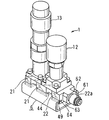
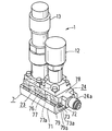
各ライン(1)(2)において、上段には、マスフローコントローラ(流量調整器)(11)と、その入口側に配された複数の流体制御機器(12)(13)(14)(15)(18)と、その出口側にそれぞれ配された複数の流体制御機器(16)(17)とが設けられている。下段には、流体制御機器(12)(13)(14)(15)(16)(17)(18)の流体通路に連通する連通通路が形成されたブロック状継手部材(21)(22)が配されている。 In each line (1) and (2), the upper stage is a mass flow controller (flow regulator) (11) and a plurality of fluid control devices (12) (13) (14) (15) arranged on the inlet side. (18) and a plurality of fluid control devices (16) and (17) respectively disposed on the outlet side thereof. The lower stage is a block-shaped joint member (21) (22) in which a communication passage communicating with the fluid passage of the fluid control device (12) (13) (14) (15) (16) (17) (18) is formed. Is arranged.
図2に示すライン(2)は、図1に示すライン(1)に1つの流体制御機器(18)が追加されたもので、ライン(2)の長さが長くなっている。 The line (2) shown in FIG. 2 is obtained by adding one fluid control device (18) to the line (1) shown in FIG. 1, and the length of the line (2) is long.
各流体制御機器(12)(13)(14)(15)(16)(17)(18)は、上方から締め付けられるおねじ部材(20)によって、対応する継手部材(21)(22)に上方に取り出し可能に取り付けられている。 Each fluid control device (12) (13) (14) (15) (16) (17) (18) is connected to the corresponding joint member (21) (22) by the male screw member (20) tightened from above. It is attached so that it can be taken out upward.
継手部材(21)(22)として、隣り合う流体制御機器(12)(13)(14)(15)(16)(17)(18)同士を接続するように配された中間継手部材(21)と、各ラインの入口側端部および出口側端部にそれぞれ配された管継手(22a)付きの端部継手部材(22)とが使用されている。中間継手部材(21)の連通通路は、V字状またはU字状とされており、端部継手部材(22)の連通通路は、L字状とされている。 Intermediate joint members (21) arranged to connect adjacent fluid control devices (12) (13) (14) (15) (16) (17) (18) as joint members (21, 22) ) And end joint members (22) with pipe joints (22a) arranged at the inlet end and the outlet end of each line, respectively. The communication passage of the intermediate joint member (21) is V-shaped or U-shaped, and the communication passage of the end joint member (22) is L-shaped.
各流体制御機器(12)(13)(14)(15)(16)(17)(18)と各継手部材(21)(22)との突き合わせ面には、連通部分をシールするシール部材(図示略)が設けられている。隣り合う継手部材(21)(22)間には、連通部分はなく、シール部材は使用されていない。 Seal members (12) (13) (14) (15) (16) (17) (18) and the joint members (21) (22) are sealed on the abutment surface of each fluid control device (12) (13) (14) (15) (16) (17) (18)) (Not shown) is provided. There is no communicating portion between the adjacent joint members (21) and (22), and no seal member is used.
各ライン(1)(2)は、ライン支持部材(3)を介してベース部材(図示略)に取り付けられるようになされており、ライン支持部材(3)としては、図1のライン(1)と図2のライン(2)とで共通のものが使用されている。 Each line (1) (2) is attached to a base member (not shown) via a line support member (3). As the line support member (3), the line (1) in FIG. And the common line (2) in FIG. 2 are used.
図1および図2に示すライン(1)(2)およびこれに類似のラインがベース部材の面に並列に配置されることで、半導体製造装置などで使用される流体制御装置の全体が形成される。 The lines (1) and (2) shown in FIGS. 1 and 2 and lines similar thereto are arranged in parallel on the surface of the base member, thereby forming the whole fluid control device used in a semiconductor manufacturing apparatus or the like. The
ライン支持部材(3)は、各継手部材(21)(22)を支持するレール(4)と、入口側端部に配置された端部継手部材(22)がレール(4)から脱落することを防止するストッパ(5)とからなる。 The line support member (3) includes a rail (4) that supports each joint member (21) (22) and an end joint member (22) arranged at the end on the inlet side that falls off the rail (4). It consists of a stopper (5) that prevents this.
各継手部材(21)(22)は、レール(4)に摺動可能に嵌め合わせられて、所定位置に配されている。 The joint members (21) and (22) are slidably fitted to the rail (4) and arranged at predetermined positions.
図3にも示すように、レール(4)は、ベース部材の面に垂直で互いに平行にのびる1対の側壁(31)と、各側壁(31)の上端部から他方の側壁(31)に向かって垂直(ベース部材の面に平行)にのびて所定の間隔をおいて対向する1対の上壁(32)と、1対の側壁(31)および1対の上壁(32)の出口側端部同士を結合する端壁(位置決め部)(33)とを有している。 As shown in FIG. 3, the rail (4) includes a pair of side walls (31) extending in parallel to each other perpendicular to the surface of the base member, and from the upper end of each side wall (31) to the other side wall (31). A pair of upper walls (32), a pair of side walls (31), and a pair of upper walls (32) exiting vertically (parallel to the surface of the base member) and facing each other at a predetermined interval And an end wall (positioning portion) (33) for joining the side end portions.
出口側に配置される端部継手部材(22)の出口側端面は、端壁(33)によって位置決めされる。端壁(33)には、端部継手部材(22)の管継手(22a)を突出させることができるように、切欠き(33a)が設けられている。 The outlet side end face of the end joint member (22) disposed on the outlet side is positioned by the end wall (33). The end wall (33) is provided with a notch (33a) so that the pipe joint (22a) of the end joint member (22) can protrude.
レール(4)の端壁(33)の下端部には、ベース部材に固定される取付部(35)が一体に形成されており、これにより、端壁(33)は、側面(レール長手方向に直交する方向)から見てL字状に形成されている。取付部(35)には、貫通孔(35a)が設けられており、ベース部材に設けられたねじ孔にこの貫通孔(35a)を合わせて、ボルトをねじ孔にねじ合わせることにより、レール(4)をベース部材に固定することができる。 At the lower end of the end wall (33) of the rail (4), a mounting portion (35) fixed to the base member is integrally formed, so that the end wall (33) has a side surface (rail longitudinal direction). It is formed in an L shape when viewed from a direction orthogonal to the direction. The mounting portion (35) is provided with a through hole (35a) .By aligning the through hole (35a) with the screw hole provided in the base member and screwing the bolt into the screw hole, the rail ( 4) can be fixed to the base member.
ストッパ(5)は、正面(レール長手方向)から見て逆U字状かつ側面(レール長手方向に直交する方向)から見てL字状に形成されており、レール(4)の端壁(33)に平行に対向し入口側の端部継手部材(22)の入口側端面に当接する当接部(36)と、当接部(36)に対して直角に連なりベース部材に固定される取付部(37)とからなる。取付部(37)には、貫通孔(37a)が設けられており、ベース部材に設けられたねじ孔にこの貫通孔(37a)を合わせて、ボルトをねじ孔にねじ合わせることにより、ストッパ(5)をベース部材に固定することができる。 The stopper (5) is formed in an inverted U shape when viewed from the front (rail longitudinal direction) and an L shape when viewed from the side surface (direction orthogonal to the rail longitudinal direction). 33) and a contact portion (36) that faces the inlet side end face of the end side joint member (22) on the inlet side and is parallel to the contact portion (36) and is fixed to the base member. It consists of a mounting part (37). The mounting portion (37) is provided with a through hole (37a) .By aligning the through hole (37a) with the screw hole provided in the base member and screwing the bolt into the screw hole, a stopper ( 5) can be fixed to the base member.
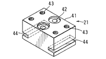
中間継手部材(21)は、図4に示すように、直方体ブロック状の本体(41)に流体制御機器(12)(13)(14)(15)(16)(17)(18)の流体通路同士を連通するためのV字状連通通路(42)が形成されているもので、本体(41)には、さらに、上面に開口して流体制御機器(12)(13)(14)(15)(16)(17)(18)を取り付けるために使用されるねじ孔(43)が設けられており、ボルト挿通孔として使用される貫通孔は設けられていないものとされている。 As shown in FIG. 4, the intermediate joint member (21) has a rectangular parallelepiped block-shaped main body (41) and a fluid control device (12) (13) (14) (15) (16) (17) (18). A V-shaped communication passage (42) for communicating the passages is formed, and the main body (41) is further opened at the upper surface to be fluid control devices (12) (13) (14) ( (15) Screw holes (43) used for attaching (16) (17) (18) are provided, and no through holes used as bolt insertion holes are provided.
本体(41)の両側面には、レール(4)の上壁(32)の内側縁部に係合するレール長手方向にのびる溝(被係合部)(44)が形成されている。この溝(44)は、中間継手部材(21)をレール(4)に摺動可能に係合させるために使用されるもので、溝(44)が対応するレール(4)の上壁(32)の内側縁部に係合することによって、中間継手部材(21)がレール(4)に支持される。 Grooves (engaged portions) (44) extending in the rail longitudinal direction that engage with the inner edge of the upper wall (32) of the rail (4) are formed on both side surfaces of the main body (41). The groove (44) is used to slidably engage the intermediate joint member (21) with the rail (4), and the groove (44) corresponds to the upper wall (32) of the corresponding rail (4). The intermediate joint member (21) is supported by the rail (4).
端部継手部材(22)は、図5に示すように、直方体ブロック状の本体(46)に流体制御機器(12)(13)(14)(15)(16)(17)(18)の流体通路同士を連通するためのL字状連通通路(47)が形成されているもので、本体(46)には、さらに、上面に開口して流体制御機器(12)(13)(14)(15)(16)(17)(18)を取り付けるために使用されるねじ孔(48)が設けられており、ボルト挿通孔として使用される貫通孔は設けられていないものとされている。 As shown in FIG. 5, the end joint member (22) has a rectangular parallelepiped block-like main body (46) attached to the fluid control device (12) (13) (14) (15) (16) (17) (18). An L-shaped communication passage (47) for communicating the fluid passages is formed, and the main body (46) is further opened to the upper surface to provide fluid control equipment (12) (13) (14) (15) A screw hole (48) used for attaching (16), (17) and (18) is provided, and a through hole used as a bolt insertion hole is not provided.
本体(46)の両側面には、レール(4)の上壁(32)の内側縁部に係合するレール長手方向にのびる溝(被係合部)(49)が形成されている。この溝(49)は、端部継手部材(22)をレール(4)に摺動可能に係合させるために使用されるもので、溝(49)が対応するレール(4)の上壁(32)の内側縁部に係合することによって、端部継手部材(22)がレール(4)に支持される。 On both side surfaces of the main body (46), grooves (engaged portions) (49) extending in the rail longitudinal direction that engage with the inner edge of the upper wall (32) of the rail (4) are formed. The groove (49) is used to slidably engage the end joint member (22) with the rail (4), and the groove (49) corresponds to the upper wall ( By engaging the inner edge of 32), the end joint member (22) is supported by the rail (4).
図1および図2において、レール(4)の上壁(32)の内側縁部は、係合部としての凸部(34)を形成しており、各継手部材(21)(22)は、溝(44)(49)より下側の部分がレール(4)の1対の側壁(31)間に収容された状態で、凸部(34)と溝(44)(49)との係合によって、その配置高さが変化することなく、レール長手方向の適切な位置まで移動可能とされている。 1 and 2, the inner edge portion of the upper wall (32) of the rail (4) forms a convex portion (34) as an engaging portion, and each joint member (21) (22) Engagement between the projections (34) and the grooves (44) (49) with the portion below the grooves (44) (49) being accommodated between the pair of side walls (31) of the rail (4) Thus, the arrangement height can be moved to an appropriate position in the rail longitudinal direction without changing.
図示省略するが、ベース部材には、適宜な位置に複数のねじ孔が設けられ、図1に示すライン(1)であっても、図2に示すライン(2)であっても、同じストッパ(5)を使用することができる。 Although not shown, the base member is provided with a plurality of screw holes at appropriate positions, and the same stopper is used for both the line (1) shown in FIG. 1 and the line (2) shown in FIG. (5) can be used.
各ライン(1)(2)は、流体制御機器(12)(13)(14)(15)(16)(17)(18)が対応する継手部材(21)(22)にボルト(20)で固定されることで一体化され、出口側端部および入口側端部に配置された端部継手部材(22)がレール(4)の端壁(33)とストッパ(5)の当接部(36)とによって挟まれることで、流体制御機器(12)(13)(14)(15)(16)(17)(18)が固定されている継手部材(21)(22)のレール長手方向の移動が阻止される。各継手部材(21)(22)は、両側面の溝(44)(49)がレール(4)の凸部(34)に係合していることで、レール(4)から上方に外れることが防止される。したがって、各継手部材(21)(22)をベース部材に直接固定することなく、各ライン(1)(2)を設置することができる。こうして、部品数を増加させることなく、各ライン(1)(2)を組み立てるための手間がかからないものとできる。 Each line (1) (2) has a bolt (20) to the joint member (21) (22) to which the fluid control device (12) (13) (14) (15) (16) (17) (18) corresponds. The end joint member (22) arranged at the outlet side end and the inlet side end is integrated with the end wall (33) of the rail (4) and the stopper (5). The rail length of the joint member (21) (22) to which the fluid control device (12) (13) (14) (15) (16) (17) (18) is fixed Directional movement is prevented. Each joint member (21) (22) must be disengaged upward from the rail (4) because the grooves (44) (49) on both sides are engaged with the projections (34) of the rail (4). Is prevented. Therefore, the lines (1) and (2) can be installed without directly fixing the joint members (21) and (22) to the base member. In this way, it is possible to save time and effort for assembling the lines (1) and (2) without increasing the number of parts.
なお、上記第1実施形態において、レール(4)に上壁(32)が設けられて、その内側縁部が係合部としての凸部(34)とされるとともに、継手部材(21)(22)に、凸部(34)に係合する被係合部としての溝(44)(49)が形成されているが、これらの係合部および被係合部の構成は、各継手部材(21)(22)がレール(4)に摺動可能に支持されるものであればよく、適宜変更することができる。 In the first embodiment, the rail (4) is provided with the upper wall (32), the inner edge thereof is formed as a convex portion (34) as an engaging portion, and the joint member (21) ( 22) are formed with grooves (44) and (49) as engaged portions that engage with the convex portions (34). (21) (22) is only required to be slidably supported on the rail (4), and can be changed as appropriate.
以下に、他の実施形態をいくつか示す。なお、以下では、流体制御装置の1つのライン(1)の端部だけを示し、ライン(1)の詳細説明を省略する。 Several other embodiments are shown below. In the following, only the end of one line (1) of the fluid control device is shown, and detailed description of the line (1) is omitted.
図6および図7は、継手部材(21)(22)が上記と同じで、被係合部としての溝(44)(49)を有しており、これを支持するレール(6)が異なるものとされたこの発明による流体制御装置および流体制御装置用継手部材の第2実施形態を示している。 6 and 7, the joint members (21) and (22) are the same as described above, and have the grooves (44) and (49) as the engaged portions, and the rails (6) that support them are different. 2 shows a second embodiment of a fluid control device and a joint member for a fluid control device according to the present invention.
図6および図7に示すように、第2実施形態のレール(6)は、ベース部材の面に垂直で互いに平行にのびる1対の側壁(61)と、各側壁(61)の上端部から他方の側壁(61)に向かって垂直(ベース部材の面に平行)にのびて所定の間隔をおいて対向する1対の上壁(62)と、1対の側壁(61)の下端部同士を連結する下壁(63)とを有している。側壁(61)、上壁(62)および下壁(63)は、互いに同じ厚さとされている。 As shown in FIGS. 6 and 7, the rail (6) according to the second embodiment includes a pair of side walls (61) extending in parallel to each other perpendicular to the surface of the base member, and an upper end of each side wall (61). A pair of upper walls (62) facing the other side wall (61) vertically (parallel to the surface of the base member) and facing each other at a predetermined interval, and the lower ends of the pair of side walls (61) And a lower wall (63) connecting the two. The side wall (61), the upper wall (62), and the lower wall (63) have the same thickness.
継手部材(21)(22)は、図4および図5に示したのと同じもので、継手部材(21)(22)に、被係合部としての溝(44)(49)が形成されている。そして、第1実施形態と同様に、レール(6)の上壁(62)の内側縁部が継手部材(21)(22)の溝(44)(49)に摺動可能に係合する係合部としての凸部(64)として使用されている。レール(6)と図3に示すストッパ(5)とによって、ライン支持部材(3)が形成される。 The joint members (21) and (22) are the same as those shown in FIGS. 4 and 5, and the joint members (21) and (22) are formed with grooves (44) and (49) as engaged portions. ing. As in the first embodiment, the inner edge of the upper wall (62) of the rail (6) is slidably engaged with the grooves (44) (49) of the joint members (21) (22). It is used as a convex part (64) as a joint part. A line support member (3) is formed by the rail (6) and the stopper (5) shown in FIG.
端壁は省略されており、各上壁(62)の出口側端部に、出口側に配置される端部継手部材(22)の出口側端面の位置決めを行う突出部(位置決め部)(65)が設けられている。また、下壁(63)の出口側端部は、上壁(62)よりも長さ方向外側に突出させられており、この部分が、ベース部材に固定される取付部(66)とされている。 The end wall is omitted, and a protruding portion (positioning portion) (65) for positioning the outlet side end surface of the end joint member (22) disposed on the outlet side at the outlet side end portion of each upper wall (62) ) Is provided. Further, the outlet side end portion of the lower wall (63) protrudes outward in the length direction from the upper wall (62), and this portion serves as an attachment portion (66) fixed to the base member. Yes.
取付部(66)には、貫通孔(66a)が設けられており、ベース部材に設けられたねじ孔にこの貫通孔(66a)を合わせて、ボルトをねじ孔にねじ合わせることにより、レール(6)をベース部材に固定することができる。 The mounting portion (66) is provided with a through hole (66a) .By aligning the through hole (66a) with the screw hole provided in the base member and screwing the bolt into the screw hole, the rail ( 6) can be fixed to the base member.
第2実施形態において、各継手部材(21)(22)の溝(44)(49)が対応するレール(6)の上壁(62)の凸部(64)に係合することによって、各継手部材(21)(22)がレール(6)に支持される。各継手部材(21)(22)は、溝(44)(49)より下側の部分がレール(6)の1対の側壁(61)間に収容された状態で、凸部(64)と溝(44)(49)との係合によって、その配置高さが変化することなく、レール長手方向の適切な位置まで移動可能とされている。各継手部材(21)(22)は、両側面の溝(44)(49)がレール(6)の凸部(64)に係合していることで、レール(6)から上方に外れることが防止される。こうして、部品数を増加させることなく、各ライン(1)を組み立てるための手間がかからないものとできる。 In the second embodiment, the grooves (44) and (49) of the joint members (21) and (22) are engaged with the convex portions (64) of the upper wall (62) of the corresponding rail (6), thereby The joint members (21) and (22) are supported by the rail (6). Each joint member (21) (22) has a convex portion (64) and a portion below the groove (44) (49) in a state in which the portion is accommodated between the pair of side walls (61) of the rail (6). By engaging with the grooves (44) and (49), the arrangement height can be changed to an appropriate position in the rail longitudinal direction without changing. Each joint member (21) (22) must be disengaged upward from the rail (6) because the grooves (44) (49) on both sides are engaged with the projections (64) of the rail (6). Is prevented. In this way, it is possible to save time and effort for assembling each line (1) without increasing the number of parts.
図8から図10までは、継手部材(23)(24)の被係合部が溝(77)(79)であり、レール(7)の係合部が凸部(73)である場合のこの発明による流体制御装置および流体制御装置用継手部材の第3実施形態を示している。 8 to 10, the engaged parts of the joint members (23) and (24) are grooves (77) and (79), and the engaging parts of the rail (7) are convex parts (73). 3 shows a third embodiment of a fluid control device and a joint member for a fluid control device according to the present invention.
図8に示すように、1つのライン(1)は、複数の流体制御機器(12)(13)と、複数の中間継手部材(23)および2つの管継手(24a)付き端部継手部材(24)と、継手部材(23)(24)を支持するレール(7)とを有している。 As shown in FIG. 8, one line (1) includes a plurality of fluid control devices (12) (13), a plurality of intermediate joint members (23), and an end joint member with two pipe joints (24a) ( 24) and a rail (7) for supporting the joint members (23) and (24).
図8および図9に示すように、第3実施形態のレール(7)は、ベース部材の面に垂直で互いに平行にのびる1対の側壁(71)と、1対の側壁(71)の下端部同士を連結する下壁(72)と、各側壁(71)の内側面の上端部から他方の側壁に向かって垂直にのびて所定の間隔をおいて対向する1対の横断面方形の凸部(73)とを有している。 As shown in FIGS. 8 and 9, the rail (7) of the third embodiment includes a pair of side walls (71) extending in parallel to each other perpendicular to the surface of the base member, and lower ends of the pair of side walls (71). A pair of rectangular projections extending in a vertical direction from the upper end of the inner surface of each side wall (71) and facing each other at a predetermined interval Part (73).
各側壁(71)は、下壁(72)および第2実施形態の側壁(61)に比べて、厚肉とされている。凸部(73)の厚み(上下方向寸法)は、側壁(71)の厚みとほぼ等しく、第2実施形態の上壁(62)の厚みの3倍程度となされている。 Each side wall (71) is thicker than the lower wall (72) and the side wall (61) of the second embodiment. The thickness (vertical dimension) of the convex part (73) is substantially equal to the thickness of the side wall (71), and is about three times the thickness of the upper wall (62) of the second embodiment.
レール(7)と図3に示すストッパ(5)とによって、ライン支持部材(3)が形成される。 A line support member (3) is formed by the rail (7) and the stopper (5) shown in FIG.
凸部(73)の上下の中間には、横断面方形の溝(73a)が全長にわたって形成されている。溝(73a)は、側壁(71)の内側面に達している。 A groove (73a) having a square cross section is formed over the entire length between the upper and lower portions of the convex portion (73). The groove (73a) reaches the inner surface of the side wall (71).
中間継手部材(23)は、図10に示すように、基本の構成として、第1実施形態の中間継手部材(21)と同様に、直方体ブロック状の本体(76)に流体制御機器(12)(13)(14)(15)(16)(17)(18)の流体通路同士を連通するためのV字状連通通路(42)が形成されており、本体(76)には、さらに、上面に開口して流体制御機器(12)(13)(14)(15)(16)(17)(18)を取り付けるために使用されるねじ孔(43)が設けられており、ボルト挿通孔として使用される貫通孔は設けられていないものとされている。 As shown in FIG. 10, the intermediate joint member (23) has a basic configuration similar to the intermediate joint member (21) of the first embodiment. (13) (14) (15) (16) (17) (18) V-shaped communication passage (42) for communicating the fluid passages is formed, the main body (76), Screw holes (43) used to attach the fluid control device (12) (13) (14) (15) (16) (17) (18) to the top surface are provided, and bolt insertion holes The through-hole used as is not provided.
中間継手部材(23)の本体(76)には、さらに、レール(7)の凸部(73)に摺動可能に係合させるための構成として、レール(7)の凸部(73)に対応する溝(77)が形成されるとともに、溝底の上下の中間に、レール(7)の溝(73a)に嵌まり合う凸部(77a)が設けられている。 The body (76) of the intermediate joint member (23) is further configured to be slidably engaged with the projection (73) of the rail (7). A corresponding groove (77) is formed, and a protrusion (77a) that fits into the groove (73a) of the rail (7) is provided in the middle of the upper and lower sides of the groove bottom.
端部継手部材(24)は、図示省略するが、基本の構成として、第1実施形態の端部継手部材(22)と同様に、直方体ブロック状の本体(78)に流体制御機器(12)(13)(14)(15)(16)(17)(18)の流体通路同士を連通するためのL字状連通通路(47)が形成されており、本体(78)には、さらに、上面に開口して流体制御機器(12)(13)(14)(15)(16)(17)(18)を取り付けるために使用されるねじ孔(48)が設けられており、ボルト挿通孔として使用される貫通孔は設けられていないものとされている。 Although the end joint member (24) is not shown in the drawing, as a basic configuration, the fluid control device (12) is connected to the rectangular parallelepiped block-shaped main body (78) as in the end joint member (22) of the first embodiment. (13) (14) (15) (16) (17) (18) An L-shaped communication passage (47) for communicating the fluid passages is formed, and the main body (78) further includes: A screw hole (48) used to mount the fluid control device (12) (13) (14) (15) (16) (17) (18) is provided in the upper surface, and the bolt insertion hole The through-hole used as is not provided.
端部継手部材(24)の本体(78)には、さらに、レール(7)の凸部(73)に摺動可能に係合させるための構成として、レール(7)の凸部(73)に対応する溝(79)が形成されるとともに、溝底の上下の中間に、レール(7)の凸部(73)の溝(73a)に嵌まり合う凸部(79a)が設けられている。 The main body (78) of the end joint member (24) is further configured to be slidably engaged with the convex portion (73) of the rail (7), and the convex portion (73) of the rail (7). The groove (79) corresponding to the groove (79) is formed, and a convex part (79a) that fits into the groove (73a) of the convex part (73) of the rail (7) is provided in the upper and lower middle of the groove bottom. .
レール(7)の端壁は省略されており、レール(7)の各側壁(71)の上面の出口側端部に、出口側に配置される端部継手部材(24)の出口側端面の位置決めを行う突出部(位置決め部)(74)が設けられている。また、下壁(72)の出口側端部は、側壁(71)よりも外側に突出させられており、この部分が、ベース部材に固定される取付部(75)とされている。 The end wall of the rail (7) is omitted, and the outlet side end face of the end joint member (24) arranged on the outlet side is formed on the outlet side end of the upper surface of each side wall (71) of the rail (7). A protruding portion (positioning portion) (74) for positioning is provided. Further, the outlet side end portion of the lower wall (72) protrudes outward from the side wall (71), and this portion serves as an attachment portion (75) fixed to the base member.
取付部(75)には、貫通孔(75a)が設けられており、ベース部材に設けられたねじ孔にこの貫通孔(75a)を合わせて、ボルトをねじ孔にねじ合わせることにより、レール(7)をベース部材に固定することができる。 The mounting portion (75) is provided with a through hole (75a) .By aligning the through hole (75a) with the screw hole provided in the base member and screwing the bolt into the screw hole, the rail ( 7) can be fixed to the base member.
第3実施形態において、各継手部材(23)(24)の溝(77)(79)が対応するレール(7)の凸部(73)に係合することによって、各継手部材(23)(24)がレール(7)に支持される。各継手部材(23)(24)は、溝(77)(79)より下側の部分がレール(7)の1対の側壁(71)間に収容された状態で、凸部(73)と溝(77)(79)との係合によって、その配置高さが変化することなく、レール長手方向の適切な位置まで移動可能とされている。各継手部材(23)(24)は、両側面の溝(77)(79)がレール(7)の凸部(73)に係合していることで、レール(7)から上方に外れることが防止される。こうして、部品数を増加させることなく、各ライン(1)を組み立てるための手間がかからないものとできる。 In the third embodiment, the grooves (77), (79) of the joint members (23), (24) are engaged with the convex portions (73) of the corresponding rails (7), so that each joint member (23) ( 24) is supported on the rail (7). Each joint member (23) (24) has a convex portion (73) and a convex portion (73) in a state where a portion below the groove (77) (79) is accommodated between the pair of side walls (71) of the rail (7). Due to the engagement with the grooves (77) and (79), the arrangement height can be changed to an appropriate position in the rail longitudinal direction without changing. Each joint member (23) and (24) is disengaged upward from the rail (7) because the grooves (77) and (79) on both sides are engaged with the projections (73) of the rail (7). Is prevented. In this way, it is possible to save time and effort for assembling each line (1) without increasing the number of parts.
なお、レール(7)の凸部(73)に設けられている溝(73a)およびこれに対応する継手部材(23)(24)の溝(77)(79)の凸部(77a)(79a)は、省略してもよい。また、上記において、レール(7)の凸部(73)に設けられている溝(73a)は、側壁(71)の内側面に達しており、凸部(73)が上下1対の横断面方形の凸条からなるものとされているが、溝(73a)の深さは、図示したものに比べて、浅くしてもよく、また、深くしてもよい。 The groove (73a) provided in the convex part (73) of the rail (7) and the convex part (77a) (79a) of the groove (77) (79) of the joint member (23) (24) corresponding thereto ) May be omitted. In the above, the groove (73a) provided in the convex portion (73) of the rail (7) reaches the inner surface of the side wall (71), and the convex portion (73) is a pair of upper and lower cross sections. The groove (73a) may be shallower or deeper than that shown in the figure, although it is made of a rectangular ridge.
図11から図13までは、継手部材(25)(26)の被係合部が溝に代えて凸部(87)(89)とされ、レール(8)の係合部が凸部に代えて溝(83)とされた場合のこの発明による流体制御装置および流体制御装置用継手部材の第4実施形態を示している。 From FIG. 11 to FIG. 13, the engaged portions of the joint members (25) and (26) are replaced with grooves, and convex portions (87) and (89), and the engaging portions of the rail (8) are replaced with convex portions. FIG. 9 shows a fluid control device and a joint member for a fluid control device according to a fourth embodiment of the present invention in the case of a groove (83).
図11に示すように、1つのライン(1)は、複数の流体制御機器(12)(13)と、複数の中間継手部材(25)および2つの管継手(26a)付き端部継手部材(26)と、継手部材(25)(26)を支持するレール(8)とを有している。 As shown in FIG. 11, one line (1) includes a plurality of fluid control devices (12) (13), a plurality of intermediate joint members (25), and an end joint member with two pipe joints (26a) ( 26) and a rail (8) for supporting the joint members (25), (26).
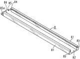
図11および図12に示すように、第4実施形態のレール(8)は、ベース部材の面に垂直で互いに平行にのびる1対の側壁(81)と、1対の側壁(81)の下端部同士を連結する下壁(82)とを有している。 As shown in FIGS. 11 and 12, the rail (8) of the fourth embodiment includes a pair of side walls (81) extending in parallel to each other perpendicular to the surface of the base member, and lower ends of the pair of side walls (81). A lower wall (82) for connecting the parts together.
各側壁(81)は、下壁(82)に比べて、厚肉とされており、各側壁(81)の内側面の上端部に、横断面方形の溝(83)がそれぞれ各側壁(81)の全長にわたって設けられている。 Each side wall (81) is thicker than the lower wall (82), and a groove (83) having a rectangular cross section is formed on each side wall (81) at the upper end of the inner side surface of each side wall (81). ) Is provided over the entire length.
レール(8)と図3に示すストッパ(5)とによって、ライン支持部材(3)が形成される。 A line support member (3) is formed by the rail (8) and the stopper (5) shown in FIG.
中間継手部材(25)は、図13に示すように、基本の構成として、第1実施形態の中間継手部材(21)と同様に、直方体ブロック状の本体(86)に流体制御機器(12)(13)(14)(15)(16)(17)(18)の流体通路同士を連通するためのV字状連通通路(42)が形成されており、本体(86)には、さらに、上面に開口して流体制御機器(12)(13)(14)(15)(16)(17)(18)を取り付けるために使用されるねじ孔(43)が設けられており、ボルト挿通孔として使用される貫通孔は設けられていないものとされている。 As shown in FIG. 13, the intermediate joint member (25) has a basic configuration similar to the intermediate joint member (21) of the first embodiment. (13) (14) (15) (16) (17) (18) V-shaped communication passage (42) for communicating the fluid passages is formed, the main body (86) further, Screw holes (43) used to attach the fluid control device (12) (13) (14) (15) (16) (17) (18) to the top surface are provided, and bolt insertion holes The through-hole used as is not provided.
中間継手部材(25)の本体(86)には、さらに、レール(8)の溝(83)に摺動可能に係合させるための構成として、レール(8)の溝(83)に対応する凸部(87)が形成されている。凸部(87)は、本体(86)の下寄りの部分に設けられている。 The body (86) of the intermediate joint member (25) further corresponds to the groove (83) of the rail (8) as a configuration for slidably engaging with the groove (83) of the rail (8). A convex part (87) is formed. The convex part (87) is provided in the lower part of the main body (86).
端部継手部材(26)は、図示省略するが、基本の構成として、第1実施形態の端部継手部材(22)と同様に、直方体ブロック状の本体(88)に流体制御機器(12)(13)(14)(15)(16)(17)(18)の流体通路同士を連通するためのL字状連通通路(47)が形成されており、本体(88)には、さらに、上面に開口して流体制御機器(12)(13)(14)(15)(16)(17)(18)を取り付けるために使用されるねじ孔(48)が設けられており、ボルト挿通孔として使用される貫通孔は設けられていないものとされている。 Although the end joint member (26) is not shown in the drawing, the basic structure is the same as that of the end joint member (22) of the first embodiment. (13) (14) (15) (16) (17) (18) An L-shaped communication passage (47) for communicating the fluid passages is formed, and the main body (88) further includes: A screw hole (48) used to mount the fluid control device (12) (13) (14) (15) (16) (17) (18) is provided in the upper surface, and the bolt insertion hole The through-hole used as is not provided.
端部継手部材(26)の本体(88)には、さらに、レール(8)の溝(83)に摺動可能に係合させるための構成として、レール(8)の溝(83)に対応する凸部(89)が形成されている。凸部(89)は、本体(86)の下寄りの部分に設けられている。 The body (88) of the end joint member (26) further corresponds to the groove (83) of the rail (8) as a configuration for slidably engaging with the groove (83) of the rail (8). A convex part (89) is formed. The convex part (89) is provided in the lower part of the main body (86).
レール(8)の端壁は省略されており、レール(8)の各側壁(81)の上面の出口側端部に、出口側に配置される端部継手部材(26)の出口側端面の位置決めを行う突出部(位置決め部)(84)が設けられている。また、下壁(82)の出口側端部は、側壁(81)よりも外側に突出させられており、この部分が、ベース部材に固定される取付部(85)とされている。 The end wall of the rail (8) is omitted, and the outlet side end face of the end joint member (26) disposed on the outlet side is provided at the outlet side end part of the upper surface of each side wall (81) of the rail (8). A protruding portion (positioning portion) (84) for positioning is provided. Further, the outlet side end portion of the lower wall (82) is projected outward from the side wall (81), and this portion serves as an attachment portion (85) fixed to the base member.
取付部(85)には、貫通孔(85a)が設けられており、ベース部材に設けられたねじ孔にこの貫通孔(85a)を合わせて、ボルトをねじ孔にねじ合わせることにより、レール(8)をベース部材に固定することができる。 The mounting portion (85) is provided with a through hole (85a) .By aligning the through hole (85a) with the screw hole provided in the base member and screwing the bolt into the screw hole, the rail ( 8) can be fixed to the base member.
第4実施形態において、各継手部材(25)(26)の凸部(87)(89)が対応するレール(8)の溝(83)に係合することによって、各継手部材(25)(26)がレール(8)に支持される。各継手部材(25)(26)は、凸部(87)(89)を含む下側の部分がレール(8)の1対の側壁(81)間に収容された状態で、溝(83)と凸部(87)(89)との係合によって、その配置高さが変化することなく、レール長手方向の適切な位置まで移動可能とされている。各継手部材(25)(26)は、両側面の凸部(87)(89)がレール(8)の溝(83)に係合していることで、レール(8)から上方に外れることが防止される。こうして、部品数を増加させることなく、各ライン(1)を組み立てるための手間がかからないものとできる。 In the fourth embodiment, the protrusions (87) and (89) of the joint members (25) and (26) are engaged with the grooves (83) of the corresponding rail (8), so that each joint member (25) ( 26) is supported on the rail (8). Each joint member (25) (26) has a groove (83) in a state where the lower portion including the convex portions (87) (89) is accommodated between the pair of side walls (81) of the rail (8). And the projections (87) and (89) are movable to an appropriate position in the rail longitudinal direction without changing the arrangement height. Each joint member (25) (26) must be disengaged upward from the rail (8) by the protrusions (87) (89) on both sides engaging the groove (83) of the rail (8). Is prevented. In this way, it is possible to save time and effort for assembling each line (1) without increasing the number of parts.
(1)(2):ライン、(3):ライン支持部材、(4)(6)(7)(8):レール、(5):ストッパ、(12)(13)(14)(15)(16)(17)(18):流体制御機器、(21)(22)(23)(24)(25)(26):継手部材、(31)(61):側壁、(33):端壁(位置決め部)、(34)(64)(73):凸部(係合部)、(35):取付部、(41)(46)(76)(78)(86)(88):本体、(42)(47):連通通路、(44)(49)(77)(79):溝、(65)(74)(84)突出部(位置決め部) (1) (2): Line, (3): Line support member, (4) (6) (7) (8): Rail, (5): Stopper, (12) (13) (14) (15) (16) (17) (18): Fluid control device, (21) (22) (23) (24) (25) (26): Fitting member, (31) (61): Side wall, (33): End Wall (positioning part), (34) (64) (73): Convex part (engaging part), (35): Mounting part, (41) (46) (76) (78) (86) (88): Main body, (42) (47): Communication passage, (44) (49) (77) (79): Groove, (65) (74) (84) Protruding part (positioning part)
Claims (4)
前記第1および第2の継手部材の被係合部に係合可能な長手方向に延在する係合部を有する支持機構と、
底面に開口する第1および第2の流路口を有する流体流路を画定するボディを含む流体制御機器と、を有し、
前記第1および第2の継手部材は、前記被係合部がそれぞれ前記支持機構の係合部に係合することにより前記長手方向に移動可能に前記支持機構に拘束され、
前記流体制御機器は、前記ボディの第1および第2の流路口が第1および第2の継手部材の上面の流路口にそれぞれ突き合わされた状態で前記ボディが前記第1および第2の継手部材の上面に設置され、前記ボディと前記第1および第2の継手部材とは締結部材によりそれぞれ連結されている、ことを特徴とする流体制御装置。 A top surface, a bottom surface facing the top surface, a side surface extending from the top surface toward the bottom surface and a fluid flow path having a flow path opening at the top surface are defined , each having an engaged portion , integrally in a block shape First and second joint members formed on
A support mechanism having an engaging portion extending in a longitudinal direction engageable with an engaged portion of the first and second joint members;
A fluid control device including a body defining a fluid flow path having first and second flow path openings opening in the bottom surface;
The first and second joint members are restrained by the support mechanism so as to be movable in the longitudinal direction by engaging the engaged parts with the engaging parts of the support mechanism,
The fluid control device is configured such that the body has the first and second joint members in a state where the first and second flow path ports of the body are abutted with the flow path ports on the upper surfaces of the first and second joint members, respectively. The fluid control apparatus is characterized in that the body and the first and second joint members are respectively connected by fastening members.
前記シール部材は前記締結部材の締め付け力により圧せられ、
前記継手部材の被係合部が溝部であり、前記支持機構の係合部が凸部であり、
前記支持機構は、互いに対向して長手方向に延在する一対の側壁と、
前記一対の側壁の一方の側壁の上端部から他方の側壁に向かって延在し、所定の間隔をおいて対向する一対の上壁と、
一対の側壁および一対の上壁の出口側端部同士を結合する端壁と、を有し、
前記継手部材の被係合部である溝部は、平面視において、前記締結部材が螺合するネジ穴と重複するように形成されている、請求項1に記載の流体制御装置。 Between the bottom surface of the body and the top surfaces of the first and second joint members, the first and second channel ports of the body and the channel ports on the top surfaces of the first and second joint members are faced to each other. A sealing member is arranged around
The sealing member is assay we are by fastening force of the fastening member,
The engaged part of the joint member is a groove part, and the engaging part of the support mechanism is a convex part,
The support mechanism includes a pair of side walls facing each other and extending in the longitudinal direction;
A pair of upper walls extending from the upper end of one side wall of the pair of side walls toward the other side wall and facing each other at a predetermined interval;
A pair of side walls and an end wall that joins the outlet side end portions of the pair of upper walls, and
The fluid control device according to claim 1, wherein a groove portion that is an engaged portion of the joint member is formed so as to overlap a screw hole into which the fastening member is screwed in a plan view.
The support mechanism includes at least one end portion in the longitudinal direction of the engagement portion, are formed to be receiving the engaged portion of each of said first and second coupling members, the fluid according to claim 1 Control device.
Priority Applications (1)
| Application Number | Priority Date | Filing Date | Title |
|---|---|---|---|
| JP2014054756A JP6347969B2 (en) | 2014-03-18 | 2014-03-18 | Fluid control device and joint member for fluid control device |
Applications Claiming Priority (1)
| Application Number | Priority Date | Filing Date | Title |
|---|---|---|---|
| JP2014054756A JP6347969B2 (en) | 2014-03-18 | 2014-03-18 | Fluid control device and joint member for fluid control device |
Publications (3)
| Publication Number | Publication Date |
|---|---|
| JP2015175502A JP2015175502A (en) | 2015-10-05 |
| JP2015175502A5 JP2015175502A5 (en) | 2016-11-24 |
| JP6347969B2 true JP6347969B2 (en) | 2018-06-27 |
Family
ID=54254863
Family Applications (1)
| Application Number | Title | Priority Date | Filing Date |
|---|---|---|---|
| JP2014054756A Active JP6347969B2 (en) | 2014-03-18 | 2014-03-18 | Fluid control device and joint member for fluid control device |
Country Status (1)
| Country | Link |
|---|---|
| JP (1) | JP6347969B2 (en) |
Families Citing this family (6)
| Publication number | Priority date | Publication date | Assignee | Title |
|---|---|---|---|---|
| WO2017221891A1 (en) * | 2016-06-21 | 2017-12-28 | 株式会社フジキン | Fluid control device |
| JP6694618B2 (en) * | 2016-06-21 | 2020-05-20 | 株式会社フジキン | Fluid control device |
| KR102237047B1 (en) | 2017-05-31 | 2021-04-08 | 가부시키가이샤 후지킨 | Valve device and fluid control device |
| WO2019167711A1 (en) | 2018-02-28 | 2019-09-06 | 株式会社フジキン | Valve device and fluid control apparatus |
| JPWO2020090521A1 (en) | 2018-10-31 | 2021-09-16 | 株式会社フジキン | Fluid control device and manufacturing method of fluid control device |
| US11906062B2 (en) | 2018-12-27 | 2024-02-20 | Fujikin Incorporated | Fluid control device, joint block and manufacturing method for fluid control device |
Family Cites Families (2)
| Publication number | Priority date | Publication date | Assignee | Title |
|---|---|---|---|---|
| JP3482601B2 (en) * | 2000-06-30 | 2003-12-22 | 東京エレクトロン株式会社 | Fluid control device |
| JP2002130479A (en) * | 2000-10-23 | 2002-05-09 | Tokyo Electron Ltd | Integrated fluid supplying device, seal material used in it, and semiconductor manufacturing device fitted therewith |
-
2014
- 2014-03-18 JP JP2014054756A patent/JP6347969B2/en active Active
Also Published As
| Publication number | Publication date |
|---|---|
| JP2015175502A (en) | 2015-10-05 |
Similar Documents
| Publication | Publication Date | Title |
|---|---|---|
| JP6347969B2 (en) | Fluid control device and joint member for fluid control device | |
| US20090183792A1 (en) | Fluid Control Device | |
| US6039360A (en) | Couplings for fluid controllers | |
| TW544751B (en) | A fluid control device | |
| US10627034B2 (en) | Manifold apparatus | |
| JP5734743B2 (en) | Protective cover device and base body | |
| JP4832428B2 (en) | Fluid control device | |
| KR20150065587A (en) | Piping joint, apparatus for controlling fluid supply and pipe jointing structure | |
| TWI687146B (en) | Housing structure | |
| US20110018261A1 (en) | Connector | |
| KR102543591B1 (en) | Fluid control device and manufacturing method of the fluid control device | |
| US20180087684A1 (en) | Fluid control system and joint block used therefor | |
| KR101117519B1 (en) | Connector for fluid pressure devices | |
| KR101537988B1 (en) | Connection device for corrugated pipes | |
| JP5738675B2 (en) | Outer corner protective cover and protective cover device | |
| JP2016048110A (en) | Manifold valve and fluid control device | |
| JP2016223534A (en) | Manifold block and fluid controller | |
| US20210125842A1 (en) | Conversion Joint, Integrated Fluid Supply Device Having Said Conversion Joint, and Method for Mounting a Fluid Part | |
| JP6175300B2 (en) | Fitting member for fluid control device and fluid control device | |
| JP2015108473A (en) | Fixing structure, and outdoor equipment | |
| KR20150031841A (en) | Connection device for corrugated pipes | |
| JPS5919190Y2 (en) | Fluid equipment connection structure | |
| KR200362304Y1 (en) | Assembly for Gas Pipe Joint equipped with Connector having Guide Flange | |
| KR102024449B1 (en) | Fixed structure of seal member, connector and fluid control device in fluid control device | |
| US11796067B2 (en) | Valve device |
Legal Events
| Date | Code | Title | Description |
|---|---|---|---|
| RD02 | Notification of acceptance of power of attorney |
Free format text: JAPANESE INTERMEDIATE CODE: A7422 Effective date: 20160524 |
|
| RD04 | Notification of resignation of power of attorney |
Free format text: JAPANESE INTERMEDIATE CODE: A7424 Effective date: 20160524 |
|
| A521 | Request for written amendment filed |
Free format text: JAPANESE INTERMEDIATE CODE: A523 Effective date: 20161011 |
|
| A621 | Written request for application examination |
Free format text: JAPANESE INTERMEDIATE CODE: A621 Effective date: 20170117 |
|
| A977 | Report on retrieval |
Free format text: JAPANESE INTERMEDIATE CODE: A971007 Effective date: 20171026 |
|
| A131 | Notification of reasons for refusal |
Free format text: JAPANESE INTERMEDIATE CODE: A131 Effective date: 20171031 |
|
| A521 | Request for written amendment filed |
Free format text: JAPANESE INTERMEDIATE CODE: A523 Effective date: 20171207 |
|
| TRDD | Decision of grant or rejection written | ||
| A01 | Written decision to grant a patent or to grant a registration (utility model) |
Free format text: JAPANESE INTERMEDIATE CODE: A01 Effective date: 20180510 |
|
| A61 | First payment of annual fees (during grant procedure) |
Free format text: JAPANESE INTERMEDIATE CODE: A61 Effective date: 20180530 |
|
| R150 | Certificate of patent or registration of utility model |
Ref document number: 6347969 Country of ref document: JP Free format text: JAPANESE INTERMEDIATE CODE: R150 |
|
| R250 | Receipt of annual fees |
Free format text: JAPANESE INTERMEDIATE CODE: R250 |
|
| R250 | Receipt of annual fees |
Free format text: JAPANESE INTERMEDIATE CODE: R250 |
|
| R250 | Receipt of annual fees |
Free format text: JAPANESE INTERMEDIATE CODE: R250 |