JP6347783B2 - Parts packaging structure for drug containers - Google Patents
Parts packaging structure for drug containers Download PDFInfo
- Publication number
- JP6347783B2 JP6347783B2 JP2015529211A JP2015529211A JP6347783B2 JP 6347783 B2 JP6347783 B2 JP 6347783B2 JP 2015529211 A JP2015529211 A JP 2015529211A JP 2015529211 A JP2015529211 A JP 2015529211A JP 6347783 B2 JP6347783 B2 JP 6347783B2
- Authority
- JP
- Japan
- Prior art keywords
- sheet
- cavity
- packaging structure
- tray
- closure part
- Prior art date
- Legal status (The legal status is an assumption and is not a legal conclusion. Google has not performed a legal analysis and makes no representation as to the accuracy of the status listed.)
- Active
Links
Images


Classifications
-
- B—PERFORMING OPERATIONS; TRANSPORTING
- B65—CONVEYING; PACKING; STORING; HANDLING THIN OR FILAMENTARY MATERIAL
- B65D—CONTAINERS FOR STORAGE OR TRANSPORT OF ARTICLES OR MATERIALS, e.g. BAGS, BARRELS, BOTTLES, BOXES, CANS, CARTONS, CRATES, DRUMS, JARS, TANKS, HOPPERS, FORWARDING CONTAINERS; ACCESSORIES, CLOSURES, OR FITTINGS THEREFOR; PACKAGING ELEMENTS; PACKAGES
- B65D25/00—Details of other kinds or types of rigid or semi-rigid containers
- B65D25/02—Internal fittings
- B65D25/10—Devices to locate articles in containers
- B65D25/108—Devices, e.g. plates, presenting apertures through which the articles project
-
- A—HUMAN NECESSITIES
- A61—MEDICAL OR VETERINARY SCIENCE; HYGIENE
- A61M—DEVICES FOR INTRODUCING MEDIA INTO, OR ONTO, THE BODY; DEVICES FOR TRANSDUCING BODY MEDIA OR FOR TAKING MEDIA FROM THE BODY; DEVICES FOR PRODUCING OR ENDING SLEEP OR STUPOR
- A61M5/00—Devices for bringing media into the body in a subcutaneous, intra-vascular or intramuscular way; Accessories therefor, e.g. filling or cleaning devices, arm-rests
- A61M5/002—Packages specially adapted therefor, e.g. for syringes or needles, kits for diabetics
-
- A—HUMAN NECESSITIES
- A61—MEDICAL OR VETERINARY SCIENCE; HYGIENE
- A61B—DIAGNOSIS; SURGERY; IDENTIFICATION
- A61B50/00—Containers, covers, furniture or holders specially adapted for surgical or diagnostic appliances or instruments, e.g. sterile covers
- A61B50/30—Containers specially adapted for packaging, protecting, dispensing, collecting or disposing of surgical or diagnostic appliances or instruments
- A61B50/33—Trays
-
- A—HUMAN NECESSITIES
- A61—MEDICAL OR VETERINARY SCIENCE; HYGIENE
- A61J—CONTAINERS SPECIALLY ADAPTED FOR MEDICAL OR PHARMACEUTICAL PURPOSES; DEVICES OR METHODS SPECIALLY ADAPTED FOR BRINGING PHARMACEUTICAL PRODUCTS INTO PARTICULAR PHYSICAL OR ADMINISTERING FORMS; DEVICES FOR ADMINISTERING FOOD OR MEDICINES ORALLY; BABY COMFORTERS; DEVICES FOR RECEIVING SPITTLE
- A61J1/00—Containers specially adapted for medical or pharmaceutical purposes
- A61J1/14—Details; Accessories therefor
- A61J1/16—Holders for containers
-
- A—HUMAN NECESSITIES
- A61—MEDICAL OR VETERINARY SCIENCE; HYGIENE
- A61J—CONTAINERS SPECIALLY ADAPTED FOR MEDICAL OR PHARMACEUTICAL PURPOSES; DEVICES OR METHODS SPECIALLY ADAPTED FOR BRINGING PHARMACEUTICAL PRODUCTS INTO PARTICULAR PHYSICAL OR ADMINISTERING FORMS; DEVICES FOR ADMINISTERING FOOD OR MEDICINES ORALLY; BABY COMFORTERS; DEVICES FOR RECEIVING SPITTLE
- A61J7/00—Devices for administering medicines orally, e.g. spoons; Pill counting devices; Arrangements for time indication or reminder for taking medicine
- A61J7/0069—Trays for holding or distributing medicines
-
- B—PERFORMING OPERATIONS; TRANSPORTING
- B65—CONVEYING; PACKING; STORING; HANDLING THIN OR FILAMENTARY MATERIAL
- B65B—MACHINES, APPARATUS OR DEVICES FOR, OR METHODS OF, PACKAGING ARTICLES OR MATERIALS; UNPACKING
- B65B7/00—Closing containers or receptacles after filling
- B65B7/16—Closing semi-rigid or rigid containers or receptacles not deformed by, or not taking-up shape of, contents, e.g. boxes or cartons
- B65B7/28—Closing semi-rigid or rigid containers or receptacles not deformed by, or not taking-up shape of, contents, e.g. boxes or cartons by applying separate preformed closures, e.g. lids, covers
- B65B7/2807—Feeding closures
-
- B—PERFORMING OPERATIONS; TRANSPORTING
- B65—CONVEYING; PACKING; STORING; HANDLING THIN OR FILAMENTARY MATERIAL
- B65D—CONTAINERS FOR STORAGE OR TRANSPORT OF ARTICLES OR MATERIALS, e.g. BAGS, BARRELS, BOTTLES, BOXES, CANS, CARTONS, CRATES, DRUMS, JARS, TANKS, HOPPERS, FORWARDING CONTAINERS; ACCESSORIES, CLOSURES, OR FITTINGS THEREFOR; PACKAGING ELEMENTS; PACKAGES
- B65D39/00—Closures arranged within necks or pouring openings or in discharge apertures, e.g. stoppers
- B65D39/0005—Closures arranged within necks or pouring openings or in discharge apertures, e.g. stoppers made in one piece
- B65D39/0023—Plastic cap-shaped hollow plugs
-
- B—PERFORMING OPERATIONS; TRANSPORTING
- B65—CONVEYING; PACKING; STORING; HANDLING THIN OR FILAMENTARY MATERIAL
- B65D—CONTAINERS FOR STORAGE OR TRANSPORT OF ARTICLES OR MATERIALS, e.g. BAGS, BARRELS, BOTTLES, BOXES, CANS, CARTONS, CRATES, DRUMS, JARS, TANKS, HOPPERS, FORWARDING CONTAINERS; ACCESSORIES, CLOSURES, OR FITTINGS THEREFOR; PACKAGING ELEMENTS; PACKAGES
- B65D65/00—Wrappers or flexible covers; Packaging materials of special type or form
- B65D65/02—Wrappers or flexible covers
-
- A—HUMAN NECESSITIES
- A61—MEDICAL OR VETERINARY SCIENCE; HYGIENE
- A61B—DIAGNOSIS; SURGERY; IDENTIFICATION
- A61B50/00—Containers, covers, furniture or holders specially adapted for surgical or diagnostic appliances or instruments, e.g. sterile covers
- A61B50/30—Containers specially adapted for packaging, protecting, dispensing, collecting or disposing of surgical or diagnostic appliances or instruments
- A61B2050/3007—Stackable casings
-
- A—HUMAN NECESSITIES
- A61—MEDICAL OR VETERINARY SCIENCE; HYGIENE
- A61J—CONTAINERS SPECIALLY ADAPTED FOR MEDICAL OR PHARMACEUTICAL PURPOSES; DEVICES OR METHODS SPECIALLY ADAPTED FOR BRINGING PHARMACEUTICAL PRODUCTS INTO PARTICULAR PHYSICAL OR ADMINISTERING FORMS; DEVICES FOR ADMINISTERING FOOD OR MEDICINES ORALLY; BABY COMFORTERS; DEVICES FOR RECEIVING SPITTLE
- A61J1/00—Containers specially adapted for medical or pharmaceutical purposes
- A61J1/14—Details; Accessories therefor
- A61J1/1412—Containers with closing means, e.g. caps
- A61J1/1425—Snap-fit type
Description
本発明は、概して、薬剤容器用部品包装構造に関する。
特に、本発明は、アンプル、バイアル、注射器及び他の薬剤容器の実装処理(装填及び閉鎖)における部品の使用又は用途まで、制御・隔離された環境並びに清浄・無菌・無毒の物理的又は化学的に安定した環境下で保存する必要のある技術的特徴を有する部品の包装構造に関する。
The present invention generally relates to a component packaging structure for a drug container.
In particular, the present invention provides a controlled and isolated environment, as well as clean, sterile, non-toxic physical or chemical, up to the use or application of parts in the mounting (loading and closing) of ampoules, vials, syringes and other drug containers. The present invention relates to a packaging structure for parts having technical characteristics that must be stored in a stable environment.
特許文献1に記載されるように、既知の薬剤容器用部品包装構造は、プラスチック材料で作られ、閉じた底部を有するトレイを備える。閉じた底部は、プラスチック材料で作られ、連続する収容穴を有する内部平面又はマトリクス(いわゆる「ネスト(nest)」を担持する。収容穴には、容器が鉛直姿勢で載置される。 As described in U.S. Patent No. 6,057,049 , a known component packaging structure for drug containers comprises a tray made of plastic material and having a closed bottom. The closed bottom is made of a plastic material and carries an internal plane or matrix (so-called “nest”) with a continuous receiving hole, in which the container is placed in a vertical position.
注射器のような幾つかの容器は、その容器の周囲のフランジが収容穴の縁部に載置されるおかげでその定位置に維持されるが、突出部を有さない他の容器は、穴の内部に収容させるための特定の要素が必要となる。 Some containers, such as syringes, are maintained in place thanks to the flange around the container being placed on the edge of the receiving hole, while other containers that do not have protrusions are A specific element is required to be housed inside.
プラスチックトレイは、ペーパーフィルタやTyvek(タイベック)(登録商標)フィルタのような多孔質メンブレンフィルタによって封止され、また、可撓性フィルムからなる更なる密閉容器によって保護される。この可撓性フィルムは、多孔質濾過メンブレン又はTyvek(タイベック)(登録商標)メンブレンによって隠された開口を有する。 The plastic tray is sealed by a porous membrane filter, such as a paper filter or a Tyvek® filter, and is protected by a further sealed container made of a flexible film. This flexible film has an opening hidden by a porous filtration membrane or a Tyvek® membrane.
従って、この包装構造は、あらゆる微生物汚染又は粒子汚染を阻止することが可能な少なくとも2つの重ねられた滅菌バリアを備え、他の容器を追加して滅菌バリアを増やすことも可能である。 The packaging structure thus comprises at least two superimposed sterilization barriers capable of preventing any microbial or particulate contamination, and additional containers can be added to increase the sterilization barrier.
そして、上述の分離されたパッケージは、梱包・開梱作業時に手で取り扱うのに適した大きさ及び重量を有するプラスチック又は段ボールで作られた容器内に載置される。 The separated package is placed in a container made of plastic or cardboard having a size and weight suitable for handling by hand during packing and unpacking operations.
容器は、一般に、(気体による)最終滅菌サイクルが施される前にパレット上に積載・載置される。 Containers are generally loaded and placed on a pallet before being subjected to a terminal sterilization cycle (by gas).
最後に、製品を使用する必要のある場合、滅菌装填プロセスを介して、汚染制御領域、例えば、滅菌ゾーンへと送られるが、作業が、ユニットを開梱する際、汚染を低下させた状態で外側容器を開封する際(この作業は、通常、超清浄空気の層流下で行われ、これにより表面を保護する)、外面の生物学的汚染を除去した後に包装を展開する際、及び、トレイのTyvek(タイベック)(登録商標)フィルタを取り外す前にその包装を無菌ゾーン内に載置する際に存在する。 Finally, if the product needs to be used, it is routed through a sterilization loading process to a contamination control area, e.g., a sterilization zone, where work is performed with reduced contamination when unpacking the unit. When opening the outer container (this operation is usually done under laminar flow of ultra-clean air, thereby protecting the surface), when unpacking the packaging after removing external biological contamination, and in the tray Present when the package is placed in the sterilization zone before removing the Tyvek® filter.
しかしながら、上記したような既知の薬剤容器用部品包装構造は、バイアルを閉鎖するためのラバーストッパー、例えばアルミニウムで作られるシールリング、及び/又は、容器の開口に対応させて載置されるスナップロックデバイスのような、薬剤容器の組み立てのために設けられる他の部品を汎用的且つ効果的に包装するのには使用できないため、その使用の柔軟性に制約がある。 However, the above-mentioned known packaging structure for drug containers has a rubber stopper for closing the vial, for example, a seal ring made of aluminum, and / or a snap lock placed in correspondence with the opening of the container. Since other parts provided for the assembly of drug containers, such as devices, cannot be used for general and effective packaging, there are restrictions on the flexibility of their use.
また、上述の部品でも、その使用まで制御・分離された滅菌環境に保持することが必然的に必要となり、そのため、すぐに使用できる滅菌パッケージの内部で包装されている。 In addition, the above-described components are necessarily maintained in a controlled and separated sterilization environment until their use, and are therefore packaged inside a sterilization package that can be used immediately.
そのため、異なる部品を、例えばヴィブラントボーラス(vibrant bolus)を用いて正しい方向に配向させ、そして複数のトラックに振り分け、そこで、自動化デバイスがそれらを取り上げ、それらを組み立て最終位置まで案内する。 Thus, the different parts are oriented in the correct direction using, for example, a vibrant bolus and distributed to multiple tracks where an automated device picks them up and guides them to the final assembly position.
上述のシステムが、容器の取り扱いから組み立て、そして最終的な自動化デバイスの終了まで、異なる部品のセットの自動化管理ができないことは明らかである。何故なら、例えば、2つの部品を単一の容器に搭載する場合(ラバーキャップ及びシールリング等)、システムを二重にしなければならず、その結果作業コストが追加され、また、自動で部品を取り上げ、取り扱い、組み立てるデバイスを用いて容器の大きさを変更することが比較的困難となるからである。 Obviously, the system described above does not allow automated management of different sets of parts from container handling to assembly and final automation device termination. This is because, for example, if two parts are mounted in a single container (such as a rubber cap and seal ring), the system must be doubled, resulting in additional operating costs and automatic parts removal. This is because it is relatively difficult to change the size of the container using a device for picking, handling and assembling.
また、容器の大きさが変更されるたびに、対応する部品を特に収容可能な各パッケージを用意・洗浄・滅菌しなければならない。 In addition, each time the size of the container is changed, each package that can specifically accommodate the corresponding part must be prepared, cleaned, and sterilized.
従って、本発明の目的は、従来技術の上述した欠点を克服すること、特に、多目的に使用できると同時に、自動機械を用いた容器の充填後、作業者の援助を必要とすることなく、適時使用できる他の付属品の異なる組の自動化管理を可能とする薬剤容器充填用部品包装構造を提供することである。 The object of the present invention is therefore to overcome the above-mentioned drawbacks of the prior art, in particular for multi-purpose use, and at the same time after filling the container with an automatic machine without the need for operator assistance. It is to provide a part packaging structure for filling a drug container that allows automated management of different sets of other accessories that can be used.
本発明の他の目的は、部品の閉鎖及びロック時の滅菌及び容器の充填処理を完了させるために典型的に必要な付属品の滅菌を確実にし、それらの品質特性の維持、保全性、識別性及び追跡性、並びに、付属物の安全な移送及び組み立てを確実にする、薬剤容器用部品包装構造を提供することである。 Another object of the present invention is to assure sterilization of the accessories typically required to complete the sterilization at the time of closure and locking of the parts and the filling process of the container, and to maintain, maintain and identify their quality characteristics. It is to provide a parts packaging structure for drug containers that ensures safety and traceability, as well as safe transport and assembly of accessories.
本発明の更なる目的は、部品及び容器の取り扱い・組み立て作業を容易にすることによって、最終製品の全体コストを低減できる薬剤容器用部品包装構造を提供することである。 It is a further object of the present invention to provide a part packaging structure for drug containers that can reduce the overall cost of the final product by facilitating handling and assembling operations of parts and containers.
有利には、本発明に係る包装構造によって、直ちに使用できるように薬剤容器に異なる部品又は付属品(例えばプラグ、クランプ、スナップロック等)を載置させることが可能となる。それらが、正確な方向に配向され正しい場所に位置付けられ、自動の取り出し・取り付けデバイス(ロボット)を用いて取り出し組み立てることができるからである。ロボットは、異なる容器の大きさに応じて予めプログラムすることができる。また、ロボットは、薬剤容器を仕上げるための取り扱い工程及び組み立て工程を正しい順序で行うようにプログラムできる。 Advantageously, the packaging structure according to the present invention allows different parts or accessories (eg plugs, clamps, snap locks, etc.) to be placed on the drug container for immediate use. This is because they are oriented in the correct direction, positioned in the correct location, and can be picked up and assembled using automatic pick and place devices (robots). The robot can be pre-programmed according to different container sizes. The robot can also be programmed to perform the handling and assembly steps for finishing the drug container in the correct order.
これにより、専用の製造ラインを、少量のものに対してまた異なる大きさに対して使用することが可能となるため、作業コストの大幅な節約、取り扱い及び組み立て作業の単純化及び効率化、並びに、容器の大きさを変更する際の速度及び効率を実現できる。 This allows a dedicated production line to be used for small quantities and for different sizes, resulting in significant savings in operating costs, simplification and efficiency of handling and assembly operations, and The speed and efficiency when changing the size of the container can be realized.
本発明の目的である薬剤容器用部品包装構造の更なる特徴及び利点は、好適な実施例に関する以下の説明及び添付の図面から明らかとなろう。 Further features and advantages of the drug container part packaging structure that is the object of the present invention will become apparent from the following description of preferred embodiments and the accompanying drawings.
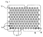
上述の図面を参照し、本発明の目的である薬剤容器用部品包装構造は、トレイ10を備える。トレイ10は通常、プラスチック材料で作られ、薬剤容器を支持する第1フラットエレメント又は棚11を挿入・取り出すための開口上部を有する。第1フラットエレメント11もポリプロピレン等のプラスチック材料で作られ、トレイ10の底面14と平行に位置付けられる。
With reference to the above-mentioned drawings, the component packaging structure for a drug container which is an object of the present invention includes a
トレイ10の開口上部は、多孔質濾過メンブレンで封止される。トレイ10は、制御された領域(例えば、容器の装填が行われる領域)での移送のための保護ラッピング又はカバーを有してもよい。保護カバーは開閉でき、迅速な移送のためのドアを備えることができる。
The upper opening of the
また、各保護カバーは、1つ以上の積層されたトレイ10及び/又は1つ以上の支持フラットエレメント11を含んでもよく、従来の滅菌処理に対して選択的に透過性を有する材料で作られるシートによって、少なくとも部分的に形成される。
Each protective cover may also include one or more
支持フラットエレメント11は、平坦な上面及び略矩形形状を有し、トレイ10の内壁15に形成された側方肩部に載置される平行且つ対向する縁部対(添付の図7及び8に詳細に示す)を有する。これらの縁部は、当接手段を介して定位置で安定する。この当接手段は、例えば、フラットエレメント11に作られた対形状(conjugated shape)を有する空洞と係合するようにトレイ10に作られた突起(あるいは逆に、トレイ10に設けられた空洞と係合するようにフラットエレメント11に作られた突起)である。
The support
更に、この支持フラットエレメント11は、鉛直シート13が所定の空間分布で配されており、その内部に、例えばアルミニウムで作られるシールリング20等の容器用クロージャ及び/又はスナップロックデバイスが、互いに対して所定の間隔で載置される。これらのクロージャ及び/又はロックデバイスは、トレイ10の底面14に対して垂直な長手方向軸線を有する。
Further, the support
本発明の第1実施例によれば、更なる支持フラットエレメント又は棚12が、支持フラットエレメント11に重ね合わせられる。フラットエレメント12も平坦面を有し、連続する空洞又はシート16を有するように成形されている。空洞又はシート16は、適切な形状の上面18を有し、フラットエレメント11の各鉛直シート13に対応して載置される。
According to a first embodiment of the invention, a further support flat element or
特に、薬剤容器を完全に組み立てるために設けられるラバープラグ17等の部品が、支持フラットエレメント12の空洞16内部の定位置に挿入・保持され、フェルール20及び/又は容器のスナップロックデバイス(ボトル、カートリッジ)等のアルミニウム及び/又はプラスチックシールも、下側のフラットエレメント11のシート13内部に載置される。
In particular, components such as a
具体的には、支持フラットエレメント12の空洞16は、ラバープラグ17が正しい位置に正確な配向で収容・維持されるように作られる。ラバープラグ17は、薬剤部品の入力領域に対応する上面18の各空洞16に一つずつ載置されてもよい。
Specifically, the
支持フラットエレメント12の上側平坦面も、空洞16の上方に保護メンブレンを載置することを可能にし、それにより、支持フラットエレメント11,12のそれぞれ一つ又は連続する積層された支持フラットエレメント11,12を更なる保護カバー内部に挿入することが可能になる。
The upper flat surface of the support
あるいは、ラバープラグ17や圧着フェルール20等の部品は、シート16内に載置する前に予め一つに組み立てることもできる。例えば、ラバープラグ17及びそのプラグ17のロックデバイスを最初に一つに組み立てた後、支持フラットエレメント12の各空洞16内部に一体のものとして位置付けることができる。一方、ロックデバイスの直径がガラス容器の直径と略等しいかそれよりも小さいかにかかわらず、支持フラットエレメント11を使用して、予め組み立てられたロックデバイス(ラバープラグ17及びフェルール又はナット20等)を支持フラットエレメント11の空洞13内部に収容することも可能である。
Alternatively, components such as the
更に、支持フラットエレメント11,12の両方は、同一の外側全体寸法を有すると共に空洞又はシート13,16の配置も同一であり、容易に積層することができるようになっている。また、空洞又はシート13,16は、プラグ17及び/又はフェルール20等のクロージャ部品を衝撃や接触、変形、表面圧力等から保護するために、マトリックスに応じて成形されると有利である。
Further, both support
他の実施例によれば、3つ以上の支持フラットエレメント11,12を積層することができる。
According to another embodiment, three or more support
また、成形領域19が、支持フラットエレメント12の空洞16の間に設けられる。この領域19は、構造の正しい保全性及び強さ、並びに、支持フラットエレメント11及び12間及び各フラットエレメント11及び12のシート13と16との間の完璧な鉛直方向中央揃えを確保するのに適切な形状を有する。
A
本発明の更なる実施例によれば、支持フラットエレメント12を使用せずに、支持フラットエレメント11を挿入するために、前もって予め組み立てられ直接連結されたラバープラグ又はストッパ17や圧着フェルール20等のロックデバイスを支持フラットエレメント11のシート13内部に設けることも可能である。有利には、この解決手段によって、部品(支持フラットエレメント12)の使用を回避することが可能になり、これにより、その支持フラットエレメント12の取り扱いに関連する相対的な滅菌上の問題が回避されるため、製造及び作業コストを節約することが可能になる。
According to a further embodiment of the present invention, in order to insert the support
このように形成された包装構造は、薬剤容器と、その内部に含まれ予め固定された空間位置に載置されるキャップ17やフェルール20等の関連するクロージャ部品とを、それらを操作するための処理装置に直接且つ自動的に送給するために使用される。典型的に、処理装置は、各クロージャ部品を取り扱うのに適した把持部材を備えるデバイス又は自動アーム(ロボット)を備える。
The packaging structure formed in this way is used to operate the drug container and the related closure parts such as the
(上側の閉鎖エレメントのない)トレイ10から取り出された後に、配向された列にグループ化された各ロック又はクロージャ部品が装填された支持フラットエレメント11,12は、ロボットヘッドの取り上げ位置へと移動される。薬剤容器を装填した後、ラバープラグ17、圧着フェルール20又は薬剤容器を閉鎖することが可能な他のスナップロックデバイス及び/又はシールといった異なるクロージャ又はロック部品を組み立ててもよい。
After removal from the tray 10 (without the upper closure element), the support
従って、本発明によれば、ただ一つの装填無菌ラインに沿って、薬剤容器の大きさに応じたラバープラグ又はストッパ17、スナップロックデバイス、シール及び/又は圧着フェルール20といったロック又はクロージャ部品を含む独立した支持フラットエレメント11,12を同時に処理することが可能であり、これにより、短時間且つ極めて効果的な方法で最終製品を直接得ることができることが明らかである。
Thus, according to the present invention, along a single loading sterilization line, including a lock or closure part such as a rubber plug or
無菌装填ラインは、実際、容器及びロック又はクロージャ部品を事前に準備(洗浄・滅菌)し、その後、部品又は環境の汚染がないようにその無菌領域へと導入する必要がある。 Aseptic loading lines actually require the container and lock or closure parts to be pre-prepared (cleaned and sterilized) and then introduced into the sterile area so that there is no contamination of the parts or the environment.
従って、その容器及びクロージャ部品の移送ラインに沿って、表面の汚染除去が可能な物理的(電子ビーム、プラズマ等)及び/又は化学的(気化させた過酸化水素水、過酢酸、二酸化塩素等)処理が行われる。 Therefore, physical (electron beam, plasma, etc.) and / or chemical (vaporized hydrogen peroxide solution, peracetic acid, chlorine dioxide, etc.) can be decontaminated along the transfer line of the container and closure parts. ) Processing is performed.
本発明の他の実施例において、濾過メンブレンで閉鎖されたトレイ10は、滅菌移送ドアを有する容器内部に包装される。その滅菌移送ドアは、その滅菌移送ドアの対応する固定位置が設けられる無菌ゾーンの壁に対応させて載置できる。このようにして、トレイ10が、汚染されることなく無菌ゾーンへと直接移送される。
In another embodiment of the invention, the
いずれの場合も、本発明によれば、単一のプロセスを通して全てのエレメントの完全な滅菌及び洗浄性を得ると共にガラス容器及び関連するクロージャ部品の大きさの変更を迅速かつ効果的な方法で実行するために、薬剤容器を収容する支持フラットエレメント11及びクロージャ部品を含む支持フラットエレメント12の両方を移送するようにこの移送ラインを計画することができる。クロージャ部品を収容する3つ以上の支持フラットエレメント11,12が設けられる場合は、更に作業コストを低減し処理効果を向上させるためにそれらを単一の外側容器内に一緒に積層することができる。
In any case, according to the present invention, complete sterilization and cleaning of all elements is achieved through a single process, and the resizing of glass containers and associated closure parts is performed in a quick and effective manner. In order to do this, this transfer line can be planned to transfer both the support
本発明の目的である薬剤容器用部品包装構造の技術的特徴は上述の説明から明らかであると共に、関連する利点も明らかである。 The technical characteristics of the component packaging structure for drug containers, which is the object of the present invention, are clear from the above description, and the related advantages are also clear.
最後に、本発明の実施において、技術的詳細の材料、形状及び大きさを要件に応じて任意のものとすることができ、また、他の技術的均等物と置き換えることができることも明らかであり、添付の特許請求の範囲において請求する本発明の思想に伴う新規性の原理から逸脱することなく他の変更を本発明の包装構造に対して行ってもよいことは明らかである。 Finally, it is clear that in the practice of the present invention, the technical details of material, shape and size can be made arbitrarily according to requirements and can be replaced by other technical equivalents. Obviously, other modifications may be made to the packaging structure of the present invention without departing from the principle of novelty associated with the spirit of the invention as claimed in the appended claims.
Claims (6)
前記少なくとも1つの第1の支持棚(11)が、前記トレイ(10)の内壁(15)に対応して載置されるとともに所定の空間分布で配された第1のシート又は空洞(13)を有し、前記第1のシート又は空洞(13)内に、前記容器の閉鎖部品及び/又は汎用付属品が載置されて、各閉鎖部品の鉛直軸線が前記トレイ(10)の前記底面(14)に対して垂直となるようになっており、前記トレイ(10)の前記開口側が、少なくとも1つの多孔質濾過メンブレンを用いて封止されており、これにより、前記シート又は空洞(13)内に挿入された前記閉鎖部品及び/又は汎用付属品の滅菌性及び清浄性が保証されるようになっており、
前記閉鎖部品の前記少なくとも1つの第1の支持棚(11)が、前記トレイ(10)の内壁(15)に対応して載置された少なくとも1つの第2の支持棚(12)に重ね合わされ、前記少なくとも1つの第2の支持棚(12)が、前記閉鎖部品の前記少なくとも1つの第1の支持棚(11)と平行であるとともに所定の空間分布で配された第2のシート又は空洞(16)を有し、前記第2のシート又は空洞(16)が、前記閉鎖部品の前記少なくとも1つの第1の支持棚(11)の前記第1のシート又は空洞(13)に対応して設けられ、
前記閉鎖部品とは異なるラバーキャップ又はプラグ(17)が、前記少なくとも1つの第2の支持棚(12)の前記第2のシート又は空洞(16)内の位置に挿入・保持されていることを特徴とする包装構造。 At least one tray (10) comprising at least one tray (10) for introducing and removing at least one first support shelf (11) parallel to the bottom surface (14) of the tray (10); In the packaging structure for drug containers (17) having an open side,
The at least one first support shelf (11) is placed corresponding to the inner wall (15) of the tray (10) and is arranged in a predetermined spatial distribution, or a first sheet or cavity (13) In the first sheet or cavity (13), the closure parts and / or general-purpose accessories of the container are placed, and the vertical axis of each closure part is the bottom surface of the tray (10) ( 14), and the opening side of the tray (10) is sealed with at least one porous filtration membrane, whereby the sheet or cavity (13) Sterilization and cleanliness of the closure part and / or general-purpose accessories inserted therein is ensured,
The at least one first support shelf (11) of the closure part is overlaid on at least one second support shelf (12) mounted corresponding to the inner wall (15) of the tray (10). A second sheet or cavity in which the at least one second support shelf (12) is parallel to the at least one first support shelf (11) of the closure part and arranged in a predetermined spatial distribution (16), wherein the second sheet or cavity (16) corresponds to the first sheet or cavity (13) of the at least one first support shelf (11) of the closure part. Provided,
A rubber cap or plug (17) different from the closure part is inserted and held in a position in the second sheet or cavity (16) of the at least one second support shelf (12). Characteristic packaging structure.
Applications Claiming Priority (3)
| Application Number | Priority Date | Filing Date | Title |
|---|---|---|---|
| ITVI2012A000215 | 2012-08-30 | ||
| IT000215A ITVI20120215A1 (en) | 2012-08-30 | 2012-08-30 | STRUCTURE FOR PACKAGING COMPONENTS FOR PHARMACEUTICAL CONTAINERS |
| PCT/IT2013/000230 WO2014033766A1 (en) | 2012-08-30 | 2013-08-28 | Components packaging structure for pharmaceutical containers |
Publications (3)
| Publication Number | Publication Date |
|---|---|
| JP2015528344A JP2015528344A (en) | 2015-09-28 |
| JP2015528344A5 JP2015528344A5 (en) | 2016-09-15 |
| JP6347783B2 true JP6347783B2 (en) | 2018-06-27 |
Family
ID=46939904
Family Applications (1)
| Application Number | Title | Priority Date | Filing Date |
|---|---|---|---|
| JP2015529211A Active JP6347783B2 (en) | 2012-08-30 | 2013-08-28 | Parts packaging structure for drug containers |
Country Status (11)
| Country | Link |
|---|---|
| US (1) | US9718583B2 (en) |
| EP (1) | EP2890423B1 (en) |
| JP (1) | JP6347783B2 (en) |
| CN (1) | CN104755115B (en) |
| BR (1) | BR112015003534B1 (en) |
| CA (1) | CA2882689C (en) |
| ES (1) | ES2599552T3 (en) |
| IN (1) | IN2015DN01399A (en) |
| IT (1) | ITVI20120215A1 (en) |
| MX (1) | MX353118B (en) |
| WO (1) | WO2014033766A1 (en) |
Families Citing this family (25)
| Publication number | Priority date | Publication date | Assignee | Title |
|---|---|---|---|---|
| CN105501503B (en) | 2012-05-03 | 2018-01-12 | 肖特公开股份有限公司 | Method and apparatus for handling or processing container |
| KR101655726B1 (en) | 2012-05-03 | 2016-09-07 | 쇼오트 아게 | Method and device for treating containers and substances stored therein for medical, pharmaceutical or cosmetic applications |
| DE102013111600B4 (en) | 2013-10-21 | 2018-04-05 | Schott Ag | Support structure for holding containers for substances for medical, pharmaceutical or cosmetic applications, as well as transport and packaging containers with the same |
| US10872313B2 (en) | 2015-06-02 | 2020-12-22 | ROCA Medical Ltd. | Method for repurposing NDC codes in a pharmaceutical database for venom derived allergens involved in venom immunotherapy |
| US10639238B2 (en) * | 2015-03-13 | 2020-05-05 | Fisher Clinical Services, Inc. | Passive cold storage container systems with packaging tray and retention plate |
| USD804052S1 (en) * | 2015-04-17 | 2017-11-28 | Schott Kaisha Pvt., Ltd. | Nest for precrimped presterilized cartridges |
| US10548974B2 (en) | 2015-06-02 | 2020-02-04 | ROCA Medical Ltd. | Therapeutic treatment kit for allergies based on DNA profiles |
| US10369215B2 (en) * | 2015-06-02 | 2019-08-06 | ROCA Medical Ltd. | Predilution sets for distributing antigens |
| DE102016123147A1 (en) * | 2016-11-30 | 2018-05-30 | Schott Ag | Support structure for simultaneously holding a plurality of vials, use thereof, and methods of treating such vials |
| USD864385S1 (en) * | 2017-07-13 | 2019-10-22 | iMed Technology, Inc. | Medical site cover mounting device |
| CN111182930B (en) * | 2017-10-02 | 2022-06-10 | 贝克顿迪金森法国公司 | Packaging device for supporting medical containers and method for removing medical containers from the packaging device |
| WO2019094547A1 (en) * | 2017-11-08 | 2019-05-16 | Windgap Medical, Inc. | A system and method for providing and assembling an auto-injector |
| EP3728062B1 (en) * | 2017-12-22 | 2022-03-02 | West Pharmaceutical Services, Inc. | Packaging system for aseptic filling of small volume vials |
| JP6694900B2 (en) * | 2018-02-08 | 2020-05-20 | 株式会社大協精工 | Holding member and syringe piston packaging structure |
| EP3563892B1 (en) * | 2018-05-02 | 2024-03-13 | Becton Dickinson France | A holding device for supporting a plurality of medical containers, a medical container pack comprising this holding device, and a method for manufacturing a medical container |
| DE102018111491A1 (en) * | 2018-05-14 | 2019-11-14 | Schott Schweiz Ag | Support structure for simultaneously holding a plurality of containers for substances for pharmaceutical, medical or cosmetic applications, transport structures and transport or packaging containers with selbiger |
| USD905267S1 (en) * | 2019-03-27 | 2020-12-15 | Avidien Technologies, Inc. | Pipette tip adapter |
| IT201900022554A1 (en) * | 2019-11-29 | 2021-05-29 | Fedegari Autoclavi | APPARATUS FOR FILLING CONTAINERS IN A STERILE ENVIRONMENT |
| US20230016662A1 (en) * | 2019-12-16 | 2023-01-19 | Merck Sharp & Dohme Llc | Pre-filled syringe stopper retainer and methods of using same |
| FR3114086B1 (en) * | 2020-09-11 | 2023-11-10 | A Raymond Et Cie | SYSTEM AND METHOD FOR PACKAGING MEDICAL CONTAINERS |
| FR3114087B1 (en) * | 2020-09-11 | 2023-07-14 | A Raymond Et Cie | SYSTEM AND METHOD FOR PACKAGING MEDICAL CAPS COMPRISING A CAP AND A STOPPER |
| EP3974337A1 (en) * | 2020-09-25 | 2022-03-30 | SCHOTT Schweiz AG | Holding device which restricts movement of primary packaging containers at first and further longitudinal positions |
| CA3231033A1 (en) * | 2021-09-15 | 2023-03-23 | Becton, Dickinson And Company | Sustainable and recyclable pulp tray for blood collection tubes |
| WO2023164771A1 (en) * | 2022-03-02 | 2023-09-07 | Medisca Pharmaceutique Inc. | Methods and assemblies for packaging containers for compositions containing active ingredients |
| CN117141791A (en) * | 2023-10-27 | 2023-12-01 | 焦作福瑞堂制药有限公司新乡分公司 | Ampoule hot-melting filling and sealing machine |
Family Cites Families (37)
| Publication number | Priority date | Publication date | Assignee | Title |
|---|---|---|---|---|
| US2523877A (en) * | 1949-09-26 | 1950-09-26 | Pestolesi August | Carrier and container for hypodermic syringes |
| US2655283A (en) * | 1951-07-26 | 1953-10-13 | St Regis Paper Co | Box construction |
| US3491894A (en) * | 1968-01-30 | 1970-01-27 | Brunswick Corp | Sterile tray |
| US4130978A (en) * | 1975-11-12 | 1978-12-26 | Medical Laboratory Automation, Inc. | Method of assembling disposable pipette tips for shipment to users thereof |
| US4349109A (en) * | 1980-10-20 | 1982-09-14 | Medical Laboratory Automation, Inc. | Disposable pipette tips and trays therefor |
| US4599314A (en) * | 1983-06-14 | 1986-07-08 | Hsc Research Development Corporation | Multiple vessel specimen tray with lid for releasably adhering vessel covers |
| US5004103A (en) * | 1989-09-11 | 1991-04-02 | Remcon Plastics, Inc. | Tool storage box |
| US5112574A (en) * | 1991-04-26 | 1992-05-12 | Imanigation, Ltd. | Multititer stopper array for multititer plate or tray |
| US5827745A (en) * | 1993-03-29 | 1998-10-27 | Astle; Thomas W. | Micropipette tip loading and unloading device and method and tip package |
| US5366088A (en) * | 1993-09-01 | 1994-11-22 | Larcon, North America | Stackable pipette tip rack |
| US5441702A (en) * | 1993-09-21 | 1995-08-15 | Rainin Instrument Co., Inc. | Refill pack for pipette tip racks |
| US5392914A (en) * | 1993-09-21 | 1995-02-28 | Rainin Instrument Co., Inc. | Refill pack for pipette tip racks |
| US6007779A (en) * | 1993-09-21 | 1999-12-28 | Rainin Instrument Co., Inc. | Refill pack for pipette tip racks |
| US5893618A (en) * | 1997-07-21 | 1999-04-13 | Poly Vac, Inc. | Stacking sterilizing tray system |
| US7060226B1 (en) * | 1997-11-24 | 2006-06-13 | Medax International, Inc. | Pipette tip packaging and transfer system |
| JP4790120B2 (en) * | 1998-03-13 | 2011-10-12 | ベクトン・ディキンソン・アンド・カンパニー | Manufacturing, filling and packaging methods for medical containers |
| FR2784076B1 (en) * | 1998-10-06 | 2000-12-22 | Gilson Sa | ASSEMBLY INCLUDING STACKED PIPETTE CONE REFILLS |
| US6286678B1 (en) * | 1999-03-05 | 2001-09-11 | Rainin Instruments Co., Inc. | Refill pack for pipette tip racks and improved pipette tip support plate for use in such packs and racks |
| US6328933B1 (en) * | 2000-03-16 | 2001-12-11 | Corning Incorporated | Double density pipette tip storage rack |
| US6566144B1 (en) * | 2000-03-27 | 2003-05-20 | Atrix Laboratories | Cover plate for use in lyophilization |
| FR2816924B1 (en) * | 2000-11-20 | 2003-02-14 | Becton Dickinson France | PACKAGING FOR STERILE PRODUCTS |
| FR2839497B1 (en) * | 2002-05-07 | 2005-04-15 | Becton Dickinson France | PACKAGING FOR USE IN TRANSPORTING STERILE OR STERILIZING OBJECTS |
| USD506833S1 (en) * | 2004-01-23 | 2005-06-28 | Wescott, Iii Harvey M. | Test platform |
| USD507658S1 (en) * | 2004-01-27 | 2005-07-19 | Wescott, Iii Harvey M. | 8GC platform |
| US7232038B2 (en) * | 2004-04-27 | 2007-06-19 | Whitney Steven G | Disposable test tube rack |
| CA2572731A1 (en) * | 2004-07-01 | 2006-03-16 | West Pharmaceutical Services, Inc. | Vacuum package system and method |
| US7963396B2 (en) * | 2004-07-01 | 2011-06-21 | West Pharmaceutical Services, Inc. | Vacuum package system |
| US8100263B2 (en) * | 2004-07-01 | 2012-01-24 | West Pharmaceutical Services, Inc. | Vacuum package system |
| FR2911072B1 (en) * | 2007-01-09 | 2010-10-22 | Becton Dickinson France | PACKAGING FOR PRODUCTS WHICH MUST BE DECONTAMINATED BY RADIATION |
| US8118167B2 (en) * | 2007-03-05 | 2012-02-21 | Daikyo Seiko, Ltd. | Medical container |
| US20090026107A1 (en) * | 2007-07-24 | 2009-01-29 | Michelle Ross | Insulin Syringe Storage Rack |
| CH702317B1 (en) * | 2007-08-02 | 2011-06-15 | Stevanato Group Internat As | Structure of the pack of glass vials for pharmaceutical use. |
| JP4616363B2 (en) * | 2008-03-05 | 2011-01-19 | 株式会社椿本チエイン | Microtube cap for drug discovery |
| JP5470369B2 (en) * | 2008-04-11 | 2014-04-16 | バイオティクス, インコーポレイテッド | Devices and methods for handling pipette tips |
| USD699859S1 (en) * | 2009-04-11 | 2014-02-18 | Biotix, Inc. | Pipette tip handling device assembly |
| US8485357B2 (en) * | 2009-07-15 | 2013-07-16 | Becton Dickinson France | Tray for positioning elongated objects, in particular syringe bodies or syringes |
| IT1399750B1 (en) * | 2010-04-30 | 2013-05-03 | Stevanato Group Internat As | PACKAGING STRUCTURE FOR PHARMACEUTICAL CONTAINERS |
-
2012
- 2012-08-30 IT IT000215A patent/ITVI20120215A1/en unknown
-
2013
- 2013-08-28 CA CA2882689A patent/CA2882689C/en active Active
- 2013-08-28 BR BR112015003534-5A patent/BR112015003534B1/en active IP Right Grant
- 2013-08-28 JP JP2015529211A patent/JP6347783B2/en active Active
- 2013-08-28 IN IN1399DEN2015 patent/IN2015DN01399A/en unknown
- 2013-08-28 US US14/423,119 patent/US9718583B2/en active Active
- 2013-08-28 CN CN201380045585.2A patent/CN104755115B/en active Active
- 2013-08-28 EP EP13780214.6A patent/EP2890423B1/en active Active
- 2013-08-28 ES ES13780214.6T patent/ES2599552T3/en active Active
- 2013-08-28 WO PCT/IT2013/000230 patent/WO2014033766A1/en active Application Filing
- 2013-08-28 MX MX2015002143A patent/MX353118B/en active IP Right Grant
Also Published As
| Publication number | Publication date |
|---|---|
| WO2014033766A1 (en) | 2014-03-06 |
| IN2015DN01399A (en) | 2015-07-03 |
| BR112015003534B1 (en) | 2021-05-11 |
| ES2599552T3 (en) | 2017-02-02 |
| MX2015002143A (en) | 2015-07-06 |
| CN104755115B (en) | 2017-12-12 |
| CN104755115A (en) | 2015-07-01 |
| EP2890423A1 (en) | 2015-07-08 |
| JP2015528344A (en) | 2015-09-28 |
| MX353118B (en) | 2017-12-20 |
| CA2882689C (en) | 2020-04-28 |
| CA2882689A1 (en) | 2014-03-06 |
| ITVI20120215A1 (en) | 2014-03-01 |
| US9718583B2 (en) | 2017-08-01 |
| US20150238263A1 (en) | 2015-08-27 |
| BR112015003534A2 (en) | 2017-07-04 |
| EP2890423B1 (en) | 2016-08-24 |
Similar Documents
| Publication | Publication Date | Title |
|---|---|---|
| JP6347783B2 (en) | Parts packaging structure for drug containers | |
| US11186390B2 (en) | Method for filling pharmaceutical containers | |
| JP5825645B2 (en) | Packaging structure for chemical containers | |
| RU2401780C2 (en) | Device and method of forming and filling container structures in sterile conditions | |
| JP2014528785A (en) | Tray and package for medical containers | |
| JP2019521813A (en) | Package opening unit | |
| TW201726098A (en) | Apparatus and method for protecting and unprotecting a fluid path in a controlled environment enclosure | |
| US8550799B2 (en) | Sterile de-molding apparatus and method | |
| JP7337142B2 (en) | Holding device for container containing filling tube and use of the device | |
| WO2023147407A2 (en) | Honeycomb cell packaging |
Legal Events
| Date | Code | Title | Description |
|---|---|---|---|
| A521 | Request for written amendment filed |
Free format text: JAPANESE INTERMEDIATE CODE: A523 Effective date: 20160725 |
|
| A621 | Written request for application examination |
Free format text: JAPANESE INTERMEDIATE CODE: A621 Effective date: 20160725 |
|
| A977 | Report on retrieval |
Free format text: JAPANESE INTERMEDIATE CODE: A971007 Effective date: 20170425 |
|
| A131 | Notification of reasons for refusal |
Free format text: JAPANESE INTERMEDIATE CODE: A131 Effective date: 20170518 |
|
| A521 | Request for written amendment filed |
Free format text: JAPANESE INTERMEDIATE CODE: A523 Effective date: 20170818 |
|
| A131 | Notification of reasons for refusal |
Free format text: JAPANESE INTERMEDIATE CODE: A131 Effective date: 20171122 |
|
| A521 | Request for written amendment filed |
Free format text: JAPANESE INTERMEDIATE CODE: A523 Effective date: 20180221 |
|
| TRDD | Decision of grant or rejection written | ||
| A01 | Written decision to grant a patent or to grant a registration (utility model) |
Free format text: JAPANESE INTERMEDIATE CODE: A01 Effective date: 20180516 |
|
| A61 | First payment of annual fees (during grant procedure) |
Free format text: JAPANESE INTERMEDIATE CODE: A61 Effective date: 20180529 |
|
| R150 | Certificate of patent or registration of utility model |
Ref document number: 6347783 Country of ref document: JP Free format text: JAPANESE INTERMEDIATE CODE: R150 |
|
| R250 | Receipt of annual fees |
Free format text: JAPANESE INTERMEDIATE CODE: R250 |
|
| R250 | Receipt of annual fees |
Free format text: JAPANESE INTERMEDIATE CODE: R250 |
|
| R250 | Receipt of annual fees |
Free format text: JAPANESE INTERMEDIATE CODE: R250 |