JP6346794B2 - Ejected sheet stacking apparatus, image reading apparatus, and image forming apparatus - Google Patents
Ejected sheet stacking apparatus, image reading apparatus, and image forming apparatus Download PDFInfo
- Publication number
- JP6346794B2 JP6346794B2 JP2014115786A JP2014115786A JP6346794B2 JP 6346794 B2 JP6346794 B2 JP 6346794B2 JP 2014115786 A JP2014115786 A JP 2014115786A JP 2014115786 A JP2014115786 A JP 2014115786A JP 6346794 B2 JP6346794 B2 JP 6346794B2
- Authority
- JP
- Japan
- Prior art keywords
- document
- sheet
- discharged
- image
- pressing
- Prior art date
- Legal status (The legal status is an assumption and is not a legal conclusion. Google has not performed a legal analysis and makes no representation as to the accuracy of the status listed.)
- Active
Links
Images


Landscapes
- Pile Receivers (AREA)
- Facsimiles In General (AREA)
Description
本発明は、シートを積載する排出シート積載装置と、この排出シート積載装置を備えた画像読取装置と、この画像読取装置を装置本体に備えた画像形成装置とに関する。 The present invention relates to a discharge sheet stacking apparatus that stacks sheets, an image reading apparatus including the discharge sheet stacking apparatus, and an image forming apparatus including the image reading apparatus in an apparatus main body.
従来、シートに画像を形成する複写機やプリンタ等の画像形成装置は、自動的に原稿の搬送、読み取りを行う画像読取装置を装置本体に備えて、画像読取装置が読み取った画像をシートに複写するようになっているものがある。しかし、最近の画像形成装置のシート搬送速度が高速化されているため、画像読取装置は、読み取った原稿を高速で排出シート積載装置に排出するようになっている。 2. Description of the Related Art Conventionally, image forming apparatuses such as copying machines and printers that form an image on a sheet are provided with an image reading apparatus that automatically conveys and reads a document in the apparatus main body, and an image read by the image reading apparatus is copied onto a sheet. There are things that are supposed to do. However, since the sheet conveyance speed of recent image forming apparatuses has been increased, the image reading apparatus discharges the read original document to the discharge sheet stacking apparatus at a high speed.
ところが、読み取りを終了した原稿が高速で排出されると、排出シート積載装置に積載される原稿の積載状態が乱れて、ユーザが原稿を揃え直す必要があった。そこで、排出される原稿を押さえ部材で押さえて原稿を揃え直す必要が無いようにした、排出シート積載装置が特許文献1に記載されている。 However, when a document that has been read is discharged at a high speed, the stacking state of the documents stacked on the discharge sheet stacking device is disturbed, and the user needs to realign the documents. In view of this, Japanese Patent Application Laid-Open No. 2004-133867 discloses a discharge sheet stacking apparatus that eliminates the need to realign the originals by pressing the discharged originals with a pressing member.
しかし、従来の排出シート積載装置の押さえ部材は容易に変形可能な材質で構成されており、排出されたシートをユーザが取り出すとき、ユーザの手が押さえ部材に触れて、原稿押さえ部材が変形するおそれがあった。このため、押さえ部材が原稿を確実に押さえることができなくなり、シートの積載状態が悪くなるという問題があった。 However, the pressing member of the conventional discharged sheet stacking apparatus is made of a material that can be easily deformed. When the user takes out the discharged sheet, the user's hand touches the pressing member, and the document pressing member is deformed. There was a fear. For this reason, the press and even members will not be able to be suppressed to ensure the document, the loading state of the sheet there is a problem that becomes worse.
本発明の目的は、シートを押さえる押さえ部材の変形を防止する排出シート積載装置と、この排出シート積載装置を備えた画像読取装置と、この画像読取装置を装置本体に備えた画像形成装置とを提供することにある。 An object of the present invention is to provide a discharge sheet stacking apparatus that prevents deformation of a pressing member that presses a sheet, an image reading apparatus including the discharge sheet stacking apparatus, and an image forming apparatus including the image reading apparatus in an apparatus main body. It is to provide.
本発明の排出シート積載装置、画像読取装置及び画像形成装置は、シートを排出する排出手段と、前記排出手段によって排出されるシートが積載される積載手段と、排出されるシートを前記積載手段に押さえる押さえ部と、前記積載手段上にシートが積載されるシート積載方向に対して前記押さえ部を回動可能とする基部と、前記押さえ部と前記基部との間に配置されて、前記基部に対して前記押さえ部を、前記積載手段上に積載されるシートのシート幅方向に揺動可能とするように前記押さえ部と前記基部とを接続する弾性変形可能な接続部と、を有するシート押さえ手段と、を備え、前記接続部の形状は、前記シート積載方向の寸法より前記シート幅方向の寸法が小さい、ことを特徴としている。 Discharged sheet stacking apparatus of the present invention, an image reading apparatus and an image forming apparatus, a discharge means for discharging the sheet, and stacking means sheet wherein Ru is discharged by the discharge means are stacked, the sheet to said stacking means to be discharged A pressing part, a base part that allows the pressing part to rotate with respect to a sheet stacking direction in which sheets are stacked on the stacking means , and a base part disposed between the pressing part and the base part. A sheet presser having an elastically deformable connecting part that connects the presser part and the base part so that the presser part can swing in the sheet width direction of the sheets stacked on the stacking means. e Bei means, the shape of the connecting portion, the sheet stacking direction is small dimensions of the seat width direction than the dimension, it is characterized in that.
本発明の排出シート積載装置、画像読取装置及び画像形成装置は、押さえ部材の変形を防止することができる。 The discharge sheet stacking apparatus, image reading apparatus, and image forming apparatus of the present invention can prevent the pressing member from being deformed .
以下、本発明の実施形態としての排出原稿積載装置と、この排出原稿積載装置を備えた画像読取装置と、この画像読取装置を装置本体に備えた画像形成装置とを図に基づいて説明する。 Hereinafter, a discharged document stacking apparatus as an embodiment of the present invention, an image reading apparatus including the discharged document stacking apparatus, and an image forming apparatus including the image reading apparatus in an apparatus main body will be described with reference to the drawings.
(画像形成装置101)
図1は、本発明の実施形態の画像形成装置101のシート搬送方向に沿った断面図である。
(Image forming apparatus 101)
FIG. 1 is a cross-sectional view of the
画像形成装置101は、例えば、複写機であり、装置本体101Aと、装置本体101Aの上部に備えられた画像読取装置104とで構成されている。画像読取装置104は、自動原稿搬送ユニット103と、画像読取ユニット102とを備えている。
The
自動原稿搬送ユニット103は、ユーザによって給紙トレイ1に載置されたシートとしての原稿Dを画像読取ユニット102に自動的に搬送するようになっている。画像読取ユニット102は、搬送されている原稿に画像読取走査部5で照射した光の反射光を受光して、原稿を光学的に読み取って電気信号に変換し、電気信号に基づいて画像データ(画像読取情報)を作成するようになっている。
The automatic
画像形成装置101の装置本体101Aは、画像データに基づいてシートに複写画像を形成するようになっている。装置本体101Aは、原稿の画像の電気信号や画像データに基づいて露光部123を作動させて、回転する感光体ドラム121の表面に静電潜像を形成する。静電潜像は、現像器124でトナー現像されてトナー画像となる。
The apparatus
一方、装置本体101Aの下部には、各種サイズのシートPを装填したシート載置部137a,137b,137c,137dが配置されている。シート載置部137a,137b,137c,137dのシートPは、それぞれ給送ローラ138a,138b,138c,138dによって1枚ずつ取り出され、搬送ローラ131へ受け渡される。シートは、手差しトレイ137eからも給送ローラ138eへ受け渡されるようになっている。
On the other hand,
その後、シートPは、レジストローラ対136によって斜行を真っ直ぐに矯正されて、かつ感光体ドラム121上のトナー画像と同期するように、感光体ドラム121と転写帯電器125との間に供給される。シートPは、転写帯電器125によって感光体ドラム上のトナー画像を転写され、分離帯電器126によって感光体ドラム121から分離される。クリーナ127は、トナー画像を転写した感光体ドラム121の表面をクリーニングする。そして、帯電器122は、次の露光に備えて感光体ドラム121の表面を帯電する。
Thereafter, the sheet P is supplied between the
一方、トナー画像を転写されたシートPは、搬送部128によって定着器129へ搬送され、定着器129で加熱と加圧を受けて表面にトナー画像を定着される。そして、トナー画像が定着されたシートPは、排出トレイ130に排出される。
On the other hand, the sheet P to which the toner image has been transferred is conveyed to the
以上説明した、画像形成装置101は、CPUを有する制御部132(図1)によって制御されるようになっている。また、感光体ドラム121、帯電器122、現像器124、定着器129等は、画像形成部133であり、画像形成部133は、画像読取装置104が読み取った原稿の画像をシートに形成するようになっている。なお、制御部132は、画像形成装置全体の動作が円滑に行えるように、画像形成装置全体を制御するようになっている。
The
図2は、本発明の実施形態における画像読取装置104の原稿搬送方向に沿った断面概略図である。画像読取装置104は、原稿を読み取る装置である。画像読取装置104は、原稿の画像を読み取る画像読取部としての画像読取ユニット102と、原稿を搬送して排出する原稿搬送部としての自動原稿搬送ユニット103とを備えている。
FIG. 2 is a schematic cross-sectional view of the
自動原稿搬送ユニット103は、主に、次の各構成要素を備えている。ユーザによって原稿Dが載置される給紙トレイ1。原稿を供給するための給紙ローラ2。供給されて搬送される原稿を案内する搬送経路3。供給された原稿を搬送する搬送ローラ対4。画像読取ユニット102に搬送されて排出された原稿が積載される排出シート積載装置としての排出原稿積載装置105。画像読取ユニット102は、供給されてきた原稿の画像を読み取る画像読取走査部5を備えている。
The automatic
排出原稿積載装置105は、主に、次の各構成要素を備えている。搬送されてきた原稿を排紙する排出手段としての排出ローラ対7。排出ローラ対7によって排出された原稿が積載される積載手段としての排出原稿積載トレイ8。排出原稿積載トレイ8に排出されたシートを排出原稿積載トレイ8に押さえるシート押さえ手段としての原稿押さえ部材10。給紙トレイ1の下側に設けられて、原稿押さえ部材10を排出原稿積載トレイ8の上方で支持する押さえ部材ホルダ9。
The discharged
画像読取装置104の動作を説明する。ユーザが原稿Dを給紙トレイ1に載置する。すると、給紙ローラ2が、原稿Dを1枚ずつ自動原稿搬送ユニット103の装置本体103A内に引き込む。その後、搬送ローラ対4が搬送経路3を案内にして原稿Dを画像読取走査部5の上に搬送する。画像読取走査部5は、原稿の画像を読み取る。そして、排出ローラ対7が原稿Dを排出原稿積載トレイ8のシート積載面としての原稿積載面8a上に排出する。このとき、原稿Dは、原稿押さえ部材10を押し退けて、排出原稿積載トレイ8に排出されて、排出原稿積載トレイ8上に原稿押さえ部材10によって押し付けられる。
The operation of the
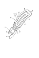
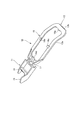
原稿押さえ部材10について説明をする。図3は、原稿押さえ部材10が給紙トレイ1の下側の押さえ部材ホルダ9に設けられている状態を示した図である。図4は、原稿押さえ部材10の外観斜視図である。図5は、図4の原稿押さえ部材10の自重軽減部13を切除した原稿押さえ部材10の斜視図である。図6は、図3の原稿押さえ部材10を下側から見た図である。図7は、原稿押さえ部材10を押さえ部材ホルダ9に取り付けた状態を示す、原稿排出方向に沿った断面図である。図8は、原稿押さえ部材10が剛性の大きい原稿D1を押さえている図である。図9は、剛性の小さい原稿D2が原稿押さえ部材10によって詰まった状態を示した図である。図10は、図9の原稿押さえ部材10から自重軽減部13を切除した原稿押さえ部材10で剛性の小さい原稿D2を押さえている図である。
The
図7において、原稿押さえ部材10は、排出原稿積載トレイ8に排出された原稿を排出原稿積載トレイ8に押さえ付けて、原稿の積載のバラツキを抑える役割を果たすように形成されている。原稿押さえ部材10は、給紙トレイ1の下部に設けられた押さえ部材ホルダ9に、排出ローラ対7による原稿排出方向(シート排出方向)Eと排出原稿積載トレイ8の原稿積載面8aとに対して、交差する方向Jに傾動可能に設けられている。矢印Jは、図2において上下方向である。図3、図4、図6において、原稿押さえ部材10は、原稿排出方向Eの上流側から下流側に順に接続した、基部11と、節部(接続部)17と、押さえ部18とを有している。
In FIG. 7, the
図4、図7において、基部11には、回転軸部14が形成されている。原稿押さえ部材10は、回転軸部14が押さえ部材ホルダ9によって給紙トレイ1に回動自在に支持されて、上下方向Jに傾動するようになっている。押さえ部材ホルダ9は、給紙トレイ1の下側(排出原稿積載トレイ8に対向する側)に着脱自在に設けられるようになっている。押さえ部材ホルダ9は、回転軸部14を支持した状態で給紙トレイ1に装着されて、原稿押さえ部材10を上下方向Jに傾動自在に支持するようになっている。また、原稿押さえ部材10には、突き当て片15が形成されている。突き当て片15は、給紙トレイ1の下側に当接して、原稿押さえ部材10の下方への回動を規制している。下方への回動を規制された原稿押さえ部材10は、接触部12の先端12bが排出原稿積載トレイ8から少し離れている。
4 and 7, the
押さえ部18は、原稿に接触する枠状の接触部12と、自重軽減部13とで形成されている。接触部12は、中間部12aで下方に屈曲して先端12bで原稿を押さえるようになっている。自重軽減部13は、押さえ部18の自重を軽くして、原稿の押さえ力を軽減するために設けられている。このため、自重軽減部13は、接触部12に切り離し部16a、16b、16c、16dによって切り離し可能に接続されている。また、自重軽減部13は、枠状の接触部12より排出原稿積載トレイ8の原稿積載面8a側に突出しないように形成されている。すなわち、自重軽減部13は、排出原稿積載トレイ8の原稿積載面8aから、接触部12より離れている。自重軽減部13が、接触部12よりも、原稿積載面8a側に突出していないことにより、自重軽減部13を切り離した際に、切り離し部16a〜16dの一部分がバリとして残るようなことがあっても、原稿がバリに引っ掛かることを防止することができる。図5、図10に示すように、図4、図9に示した自重軽減部13を切り取ると、原稿押さえ部材10の自重を軽くして、原稿を押さえ力をF1からF2(<F1)に軽減することができる。
The
ところで、原稿押さえ部材10は、給紙トレイ1の下側に押さえ部材ホルダ9によって設けられて、給紙トレイ1の陰になって、ユーザが目視しにくい位置に配置されている。このため、ユーザが、画像読み込みを終えた原稿を回収する際に、給紙トレイ1と排出原稿積載トレイ8との間に、原稿押さえ部材10に気付かずに手を差し込むと、原稿押さえ部材10に手をぶつけるおそれがある。
By the way, the
そこで、本実施形態の排出原稿積載装置105の原稿押さえ部材10は、基部11と押さえ部18とを弾性変形可能な節部17で接続して、原稿押さえ部材10の先端部の押さえ部18に、ユーザの手が干渉しても、押さえ部18が逃げるようにしてある。節部17は、基部11の傾動方向J(シート積載方向)の寸法L1の方が、基部11の傾動方向Jに対して交差する方向K(揺動方向)の寸法L2よりも大きく(L1>L2)設定されている。このため、図3において、節部17は、排出原稿積載トレイ8の原稿積載面8aに沿った方向Kに弾性変形可能にしてあり、ユーザの手が押さえ部18に干渉しても、押さえ部18を逃がして、原稿押さえ部材10の損傷を防止することができる。また、原稿押さえ部材10は、節部17がL1>L2の関係によって原稿積載面8aに対して交差する方向Jに弾性変形しにくくなっているので、自重を有効に利用して、原稿を排出原稿積載トレイ8に押さえることができる。
Therefore, the
なお、原稿押さえ部材10に使用される材料は、熱可塑性エラストマー特性を備えて、成形性、用紙接触面や軸部の摺動性、最適な剛性のすべてを兼ね備えたポリエステル・エラストマーである。なお、ポリエステル・エラストマーに限定されることなく、ポリエステル・エラストマーと同様な特性、成形性、摺動性等を備えている他の材料を使用してもよい。
The material used for the
以上説明した、原稿押さえ部材10は、排出原稿積載トレイ8に排出された原稿を、自重によって、排出原稿積載トレイ8に押し付けて、原稿の積載のバラツキを少なくすることができる。なお、原稿押さえ部材10は、原稿の後端が排出ローラ対7を通過し終わる前に、原稿に接触する位置に配置されている。
The
ところで、原稿によっては、剛性の大小(コシの強弱)がある。そこで、排出された原稿が、ある一定の剛性(一定のコシの強さ)を有している原稿D1(図8)の場合、原稿D1は、先端(図8において右端)で原稿押さえ部材10を押し上げて下流側に搬送される。この場合、原稿押さえ部材10は、押さえ部材ホルダ9に回転支持された回転軸部14を中心にして押し上げられて回転する。しかし、原稿が剛性の小さい(コシが弱い)薄紙D2の場合(図9)、薄紙D2は、先端(図9において右端)で原稿押さえ部材10を押し上げることが困難であり、排出原稿積載トレイ8の原稿積載面8aと原稿押さえ部材10との間に詰まるおそれがある。
By the way, depending on the manuscript, there is a size of rigidity (strength of strength). Therefore, when the discharged document is a document D1 (FIG. 8) having a certain rigidity (a certain stiffness), the document D1 is a
このように、原稿押さえ部材10を押し上げられない原稿がある場合は、原稿押さえ部
材10の自重軽減部(中央部分)13を切り取ると(図10)、原稿押さえ部材10の原稿押さえ力をF1からF2に減少させることができて、原稿が詰まることを防止することができる。
As described above, when there is a document in which the
以上の開示した内容の主要部を示すと次の通りである。なお、各構成要件に付した括弧内の数字は、各構成要件と図面とを対比し易いようにするための図面の符号であり、特許請求範囲に記載の各構成要件に何等影響を及ぼすものではない。 The main parts of the above disclosed contents are as follows. The numbers in parentheses attached to each constituent element are symbols of the drawing for facilitating comparison between each constituent element and the drawing, and have no influence on each constituent element described in the claims. is not.
排出シート積載装置(105)は、
シートを排出する排出手段(7)と、
排出手段によって排出されたシートが積載される積載手段(8)と、
積載手段に排出されたシートを積載手段に押さえる押さえ部(18)と、積載手段の上方に配置された基部(11)と、押さえ部と基部との間に設けられた節部(17)と、を有するシート押さえ手段(10)と、を備えている。
The discharge sheet stacking device (105)
Discharging means (7) for discharging the sheet;
A stacking means (8) on which sheets discharged by the discharging means are stacked;
A pressing portion (18) for pressing the sheet discharged to the stacking means to the stacking means, a base portion (11) disposed above the stacking means, and a node portion (17) provided between the pressing portion and the base portion And a sheet pressing means (10).
そして、基部(11)は、積載手段(8)のシート積載方向(矢印Jの下向きの矢印の方向)へ押さえ部(18)を回動可能に配置され、押さえ部は、節部によって基部の回動方向と交差する方向に揺動可能である、ことを特徴としている。 The base portion (11) is disposed so that the pressing portion (18) can be rotated in the sheet stacking direction of the stacking means (8) (the direction of the arrow pointing downwards of the arrow J). It is characterized in that it can be swung in a direction crossing the rotation direction.
このような構成における、本実施形態の排出原稿積載装置105は、排出された原稿をユーザが取り出すとき、ユーザの手が原稿押さえ部材10に触れても、節部17が弾性変形して、押さえ部18が逃げるので、押さえ部材10の変形が防止される。これによって、排出原稿積載装置は、原稿押さえ部材で原稿を押さえ損なうことがなく、原稿の積載の乱れを防止して、ユーザが再度、原稿を揃え直す必要が無くなる。
In this configuration, the discharged
また、本実施形態の画像読取装置104は、原稿を揃え直す必要の無い排出原稿積載装置105を備えているので、取扱いが容易である。
In addition, the
さらに、本実施形態の画像形成装置101は、シートを揃え直す必要の無い排出原稿積載装置105を備えた画像読取装置104を備えているので、取扱いが容易である。
Furthermore, since the
7:排出ローラ対(排出手段)、8:排出原稿積載トレイ(積載手段)、8a:原稿積載面(シート積載面)、10:原稿押さえ部材(シート押さえ手段)、11:基部、13:自重軽減部(中央部分)、17:節部(接続部)、18:押さえ部、101:画像形成装置、101A:画像形成装置の装置本体、102:画像読取ユニット(画像読取部)、103:自動原稿搬送ユニット(原稿搬送部)、104:画像読取装置、105:排出原稿積載装置(排出シート積載装置)、133:画像形成部、D:原稿、D1:剛性の大きい原稿(コシの強い原稿)、D2:剛性の小さい原稿(コシの弱い原稿)、P:シート、E:原稿排出方向(シート排出方向)、J:原稿押さえ部材の傾動方向、K:押さえ部の傾き方向。
7: discharge roller pair (discharge unit), 8: discharged document stacking tray (stacking unit), 8a: document stacking surface (sheet stacking surface), 10: document pressing member (sheet pressing unit), 11: base, 13: own weight Reduction part (center part) 17: Node part (connection part) 18: Pressing part 101:
Claims (8)
前記排出手段によって排出されるシートが積載される積載手段と、
排出されるシートを前記積載手段に押さえる押さえ部と、前記積載手段上にシートが積載されるシート積載方向に対して前記押さえ部を回動可能とする基部と、前記押さえ部と前記基部との間に配置されて、前記基部に対して前記押さえ部を、前記積載手段上に積載されるシートのシート幅方向に揺動可能とするように前記押さえ部と前記基部とを接続する弾性変形可能な接続部と、を有するシート押さえ手段と、を備え、
前記接続部の形状は、前記シート積載方向の寸法より前記シート幅方向の寸法が小さい、
ことを特徴とする排出シート積載装置。 Discharging means for discharging the sheet;
And stacking means sheet that will be discharged are stacked by said discharge means,
A pressing portion that presses the discharged sheets to the stacking unit, a base that allows the pressing unit to rotate with respect to a sheet stacking direction in which the sheets are stacked on the stacking unit, and the pressing unit and the base is disposed between, said pressing portion relative to the base, said swingable sheet width direction of the sheets loaded on the loading means and said pressing portion elastically deformable for connecting the base to Bei example a sheet pressing means has a Do connecting portion, and the,
The shape of the connecting portion is smaller in the sheet width direction than in the sheet stacking direction.
A discharge sheet stacking apparatus characterized by that.
ことを特徴とする請求項1に記載の排出シート積載装置。 The pressing part is separable at the center part,
The discharged sheet stacking apparatus according to claim 1.
ことを特徴とする請求項2に記載の排出シート積載装置。 The pressing portion reduces the pressing force for pressing the sheet by separating the central portion .
The discharged sheet stacking apparatus according to claim 2 , wherein:
ことを特徴とする請求項2または請求項3に記載の排出シート積載装置。 The central portion is provided at a position that does not contact the sheet discharged from the discharge means.
The discharged sheet stacking apparatus according to claim 2 or claim 3, wherein
ことを特徴とする請求項1乃至4のいずれか1項に記載の排出シート積載装置。 It said sheet pressing means is formed of a material which have a thermoplastic elastomeric properties,
The discharged sheet stacking apparatus according to claim 1, wherein the discharged sheet stacking apparatus is provided.
前記画像読取部に原稿を搬送する原稿搬送部と、を備え、
前記原稿搬送部は、前記画像読取部に搬送して排出された原稿が積載される請求項1乃
至5のいずれか1項に記載の排出シート積載装置を有している、
ことを特徴とする画像読取装置。 An image reading unit for reading an image of a document;
A document conveying unit that conveys the document to the image reading unit,
6. The discharge sheet stacking apparatus according to claim 1, wherein the document transport unit includes a document that is transported and discharged to the image reading unit.
An image reading apparatus.
前記画像読取装置によって読み取られた画像をシートに形成する画像形成部と、を備え
た、
ことを特徴とする画像形成装置。 An image reading apparatus according to claim 6;
An image forming unit that forms an image read by the image reading device on a sheet,
An image forming apparatus.
前記画像形成手段にて画像が形成されたシートを排出する請求項1乃至5のいずれか1項に記載の排出シート積載装置と、を備えた、
ことを特徴とする画像形成装置。 Image forming means for forming an image on a sheet;
Equipped with a discharged sheet stacking apparatus according to any one of claims 1 to 5 for discharging the sheet on which the image is formed by the image forming means,
An image forming apparatus.
Priority Applications (1)
| Application Number | Priority Date | Filing Date | Title |
|---|---|---|---|
| JP2014115786A JP6346794B2 (en) | 2014-06-04 | 2014-06-04 | Ejected sheet stacking apparatus, image reading apparatus, and image forming apparatus |
Applications Claiming Priority (1)
| Application Number | Priority Date | Filing Date | Title |
|---|---|---|---|
| JP2014115786A JP6346794B2 (en) | 2014-06-04 | 2014-06-04 | Ejected sheet stacking apparatus, image reading apparatus, and image forming apparatus |
Publications (3)
| Publication Number | Publication Date |
|---|---|
| JP2015229549A JP2015229549A (en) | 2015-12-21 |
| JP2015229549A5 JP2015229549A5 (en) | 2017-07-13 |
| JP6346794B2 true JP6346794B2 (en) | 2018-06-20 |
Family
ID=54886548
Family Applications (1)
| Application Number | Title | Priority Date | Filing Date |
|---|---|---|---|
| JP2014115786A Active JP6346794B2 (en) | 2014-06-04 | 2014-06-04 | Ejected sheet stacking apparatus, image reading apparatus, and image forming apparatus |
Country Status (1)
| Country | Link |
|---|---|
| JP (1) | JP6346794B2 (en) |
Families Citing this family (2)
| Publication number | Priority date | Publication date | Assignee | Title |
|---|---|---|---|---|
| CN108778971B (en) * | 2016-04-15 | 2021-01-22 | 惠普发展公司,有限责任合伙企业 | Rotating and oscillating platen arm |
| JP7402670B2 (en) | 2019-12-19 | 2023-12-21 | 株式会社Pfu | media ejector |
Family Cites Families (4)
| Publication number | Priority date | Publication date | Assignee | Title |
|---|---|---|---|---|
| US5228679A (en) * | 1990-04-19 | 1993-07-20 | Xerox Corporation | Sheet damping mechanism |
| JPH04117864U (en) * | 1991-04-05 | 1992-10-21 | 株式会社リコー | paper stacking device |
| JP2011020783A (en) * | 2009-07-15 | 2011-02-03 | Fuji Xerox Co Ltd | Document feeder, image reader and image forming device |
| JP5526083B2 (en) * | 2011-07-05 | 2014-06-18 | 京セラドキュメントソリューションズ株式会社 | Image forming apparatus |
-
2014
- 2014-06-04 JP JP2014115786A patent/JP6346794B2/en active Active
Also Published As
| Publication number | Publication date |
|---|---|
| JP2015229549A (en) | 2015-12-21 |
Similar Documents
| Publication | Publication Date | Title |
|---|---|---|
| EP1820760A1 (en) | Apparatus for separating sheets from a pile comprising blowing means to assist separation | |
| JP2006056713A (en) | Sheet processing device and image forming device having the same | |
| JP2008120556A (en) | Sheet handling device and image forming device using the same | |
| JP6346794B2 (en) | Ejected sheet stacking apparatus, image reading apparatus, and image forming apparatus | |
| JP2008120557A (en) | Sheet chip handling device and image forming device using the same | |
| JP2020196567A (en) | Sheet discharge device, image reading apparatus and image formation apparatus | |
| JP2009091143A (en) | Sheet separation/conveyance mechanism, and sheet conveying device and image forming device provided therewith | |
| JP6361637B2 (en) | Document conveying apparatus and image forming apparatus having the same | |
| JP2009098387A (en) | Image forming apparatus | |
| JP2011173731A (en) | Image forming device | |
| JP7005299B2 (en) | Sheet holding mechanism and image forming device | |
| JP2007197162A (en) | Image forming device | |
| JP2007197191A (en) | Manual paper feeder and image forming device having this paper feeder | |
| JP2019174615A (en) | Sheet conveyance device and image formation device | |
| US8964199B2 (en) | Image forming apparatus | |
| JP4560282B2 (en) | Image forming apparatus | |
| JP2010058944A (en) | Sheet post-processing device | |
| JP2017077932A (en) | Document conveying device and image forming device including the same | |
| JP6531737B2 (en) | Sheet post-processing apparatus and image forming system provided with the same | |
| JP5810730B2 (en) | Image forming apparatus | |
| JP2011088734A (en) | Sheet accumulating mechanism and image forming device incorporating sheet accumulating mechanism | |
| JP2022037792A (en) | Sheet conveying apparatus, and image forming apparatus comprising the same | |
| JP2021187610A (en) | Sheet discharger and image forming apparatus | |
| JP2009202987A (en) | Paper guiding device, document conveying device therewith, and image forming device | |
| JP2005298166A (en) | Paper feeding device and image forming device provided with the same |
Legal Events
| Date | Code | Title | Description |
|---|---|---|---|
| A521 | Request for written amendment filed |
Free format text: JAPANESE INTERMEDIATE CODE: A523 Effective date: 20170529 |
|
| A621 | Written request for application examination |
Free format text: JAPANESE INTERMEDIATE CODE: A621 Effective date: 20170529 |
|
| A131 | Notification of reasons for refusal |
Free format text: JAPANESE INTERMEDIATE CODE: A131 Effective date: 20180213 |
|
| A977 | Report on retrieval |
Free format text: JAPANESE INTERMEDIATE CODE: A971007 Effective date: 20180215 |
|
| A521 | Request for written amendment filed |
Free format text: JAPANESE INTERMEDIATE CODE: A523 Effective date: 20180416 |
|
| TRDD | Decision of grant or rejection written | ||
| A01 | Written decision to grant a patent or to grant a registration (utility model) |
Free format text: JAPANESE INTERMEDIATE CODE: A01 Effective date: 20180508 |
|
| A61 | First payment of annual fees (during grant procedure) |
Free format text: JAPANESE INTERMEDIATE CODE: A61 Effective date: 20180528 |
|
| R150 | Certificate of patent or registration of utility model |
Ref document number: 6346794 Country of ref document: JP Free format text: JAPANESE INTERMEDIATE CODE: R150 |
|
| R250 | Receipt of annual fees |
Free format text: JAPANESE INTERMEDIATE CODE: R250 |
|
| R250 | Receipt of annual fees |
Free format text: JAPANESE INTERMEDIATE CODE: R250 |
|
| R250 | Receipt of annual fees |
Free format text: JAPANESE INTERMEDIATE CODE: R250 |