JP6346185B2 - Expanded rigid wing - Google Patents
Expanded rigid wing Download PDFInfo
- Publication number
- JP6346185B2 JP6346185B2 JP2015534884A JP2015534884A JP6346185B2 JP 6346185 B2 JP6346185 B2 JP 6346185B2 JP 2015534884 A JP2015534884 A JP 2015534884A JP 2015534884 A JP2015534884 A JP 2015534884A JP 6346185 B2 JP6346185 B2 JP 6346185B2
- Authority
- JP
- Japan
- Prior art keywords
- rigid
- rigid wing
- wing sail
- panels
- pair
- Prior art date
- Legal status (The legal status is an assumption and is not a legal conclusion. Google has not performed a legal analysis and makes no representation as to the accuracy of the status listed.)
- Active
Links
Images


Classifications
-
- B—PERFORMING OPERATIONS; TRANSPORTING
- B63—SHIPS OR OTHER WATERBORNE VESSELS; RELATED EQUIPMENT
- B63H—MARINE PROPULSION OR STEERING
- B63H9/00—Marine propulsion provided directly by wind power
- B63H9/04—Marine propulsion provided directly by wind power using sails or like wind-catching surfaces
- B63H9/06—Types of sail; Constructional features of sails; Arrangements thereof on vessels
- B63H9/061—Rigid sails; Aerofoil sails
-
- B—PERFORMING OPERATIONS; TRANSPORTING
- B63—SHIPS OR OTHER WATERBORNE VESSELS; RELATED EQUIPMENT
- B63H—MARINE PROPULSION OR STEERING
- B63H9/00—Marine propulsion provided directly by wind power
- B63H9/04—Marine propulsion provided directly by wind power using sails or like wind-catching surfaces
- B63H9/08—Connections of sails to masts, spars, or the like
-
- B—PERFORMING OPERATIONS; TRANSPORTING
- B63—SHIPS OR OTHER WATERBORNE VESSELS; RELATED EQUIPMENT
- B63H—MARINE PROPULSION OR STEERING
- B63H9/00—Marine propulsion provided directly by wind power
- B63H9/04—Marine propulsion provided directly by wind power using sails or like wind-catching surfaces
- B63H9/06—Types of sail; Constructional features of sails; Arrangements thereof on vessels
- B63H9/061—Rigid sails; Aerofoil sails
- B63H9/0621—Rigid sails comprising one or more pivotally supported panels
- B63H9/0635—Rigid sails comprising one or more pivotally supported panels the panels being pivotable about vertical axes
Landscapes
- Engineering & Computer Science (AREA)
- Life Sciences & Earth Sciences (AREA)
- Sustainable Development (AREA)
- Sustainable Energy (AREA)
- Chemical & Material Sciences (AREA)
- Combustion & Propulsion (AREA)
- Mechanical Engineering (AREA)
- Ocean & Marine Engineering (AREA)
- Wind Motors (AREA)
- Hinges (AREA)
Description
本発明は、広義には剛性翼に関し、排他的ではないが特に、船舶を推進させるための剛性翼型帆に関する。 The present invention relates to rigid wings in a broad sense, and more particularly, but not exclusively, to rigid wing sails for propelling ships.
風により推進させる水上船舶を設計する際に、特注の帆が、特定の帆船および構成のために製造される。特注の帆は、しなやかで柔軟性のある帆布から製造され、典型的には、柔らかい帆と称される。設計者や帆製造業者は特定の帆船の効率的な設計を提供するが、柔らかい帆は、風上に向かって帆走しているときに、例えば、帆を風に対して鋭角に傾斜させた場合に、強風で変形する、すなわち「はためく」。 In designing a watercraft to be propelled by wind, custom sails are manufactured for specific sailboats and configurations. Custom sails are manufactured from flexible and flexible canvases and are typically referred to as soft sails. Designers and sail manufacturers offer efficient designs for certain sailing vessels, but soft sails are sailing towards the windward, for example when the sail is tilted at an acute angle to the wind In addition, it is deformed by a strong wind, that is, “flapping”.
柔らかい帆での帆の調節に依存する効率上の欠陥に対処する上で、ここ最近では、特にレース用帆船に剛性翼型帆が採用されている。剛性翼型帆が取り付けられる水上船舶の最も効率的な操作および推進のために風に対するこの翼型帆の迎え角を調節するために、剛性翼型帆を枢動または旋回させることができる。剛性翼型帆は、一般に、船舶が左舷開きであるか右舷開きであるかによっていずれかの側で揚力を生じさせることを可能にする対称部分を有する。しかしながら、剛性翼型帆には少なくとも以下の欠点がある。(i)剛性翼型帆は、強風の際に「縮帆」により翼型帆の面積を減少させることまたは微風の際に「展帆」により翼型帆の面積を増大させることができない。(ii)剛性翼型帆はキャンバーを変化させることができない。(iii)剛性翼型帆は、空気抵抗が最小にされる、すなわち「フェザリングされる(feathered)」および風向に平行に配置されるときでさえ、制御するおよび空気抵抗を最小にすることが困難である。 Recently, rigid winged sails have been employed, particularly in racing sailing vessels, to address efficiency deficiencies that depend on sail adjustment with soft sails. The rigid wing sail can be pivoted or swiveled to adjust the angle of attack of the wing sail with respect to the wind for the most efficient operation and propulsion of the surface vessel to which the rigid wing sail is attached. Rigid airfoil sails generally have symmetrical portions that allow lift to be generated on either side depending on whether the ship is port-side or starboard-open. However, rigid wing sails have at least the following drawbacks. (I) The rigid wing type sail cannot reduce the area of the wing type sail by “shrinking” in a strong wind or increase the area of the wing type sail by “extended sail” in a slight wind. (Ii) The rigid wing sail cannot change the camber. (Iii) Rigid airfoil sails can control and minimize air resistance even when air resistance is minimized, ie “feathered” and placed parallel to the wind direction Have difficulty.
本発明によれば、側縁部に対向する隣接縁部を各々有する1対の細長い剛性パネルと、剛性パネルの互いに対する枢動を可能にし、(i)剛性パネルの側縁部が互いに隣接する閉形態であって、剛性翼が実質的に閉じられる閉形態か、または(ii)細長い剛性パネルの側縁部が互いに隔てられる開形態であって、剛性翼が可変キャンバーとされる開形態のいずれかを形成するために、1対の細長い剛性パネルにそれらの隣接縁部でまたは隣接縁部付近で連結されたヒンジ要素とを備える、剛性翼が提供される。 According to the present invention, a pair of elongated rigid panels each having an adjacent edge opposite the side edges and the rigid panels can be pivoted relative to each other, (i) the side edges of the rigid panels are adjacent to each other. A closed configuration in which the rigid wing is substantially closed, or (ii) an open configuration in which the side edges of the elongated rigid panel are separated from each other, wherein the rigid wing is a variable camber. To form either, a rigid wing is provided that comprises a pair of elongated rigid panels with hinge elements connected at or near their adjacent edges.
好ましくは、1対のパネルの各々は、剛性材料の1つの連続片である。 Preferably, each of the pair of panels is one continuous piece of rigid material.
好ましくは、剛性翼は翼型帆である。 Preferably, the rigid wing is a wing sail.
好ましくは、1対のパネルは各々、非対称な断面形状の湾曲したパネルである。より好ましくは、1対のパネルは、実質的に同一の外形および断面形状を有する。より更に好ましくは、可変キャンバーの剛性翼は、ヒンジ要素の両側で対称である。 Preferably, each of the pair of panels is a curved panel having an asymmetric cross-sectional shape. More preferably, the pair of panels have substantially the same outer shape and cross-sectional shape. Even more preferably, the rigid wings of the variable camber are symmetrical on both sides of the hinge element.
好ましくは、ヒンジ要素は、パネルの隣接縁部が枢動するシャフトを含む。より好ましくは、ヒンジ要素は、ピアノ型ヒンジの形態である。 Preferably, the hinge element includes a shaft about which the adjacent edge of the panel pivots. More preferably, the hinge element is in the form of a piano hinge.
代替的に、剛性翼はまた、剛性翼を更に開くためにヒンジ要素の軸線に平行に配設されかつこの軸線から離間された他のヒンジ要素と、折り畳まれるときに、剛性翼の外面形状が翼形断面を形成するように内側に折り畳まれる細長いパネルとを備える。 Alternatively, the rigid wing also has an outer shape of the rigid wing when folded with another hinge element disposed parallel to and spaced from the axis of the hinge element to further open the rigid wing. And an elongated panel that is folded inward to form an airfoil cross section.
好ましくは、剛性翼は、前記パネルの互いに対する枢動のためのヒンジ要素に動作可能に連結されたヒンジ作動手段を更に備える。より好ましくは、ヒンジ作動手段は、細長いパネルおよびヒンジ要素の少なくとも一方に動作可能に連結された1つまたは複数の歯車を含む。 Preferably, the rigid wing further comprises hinge actuating means operably connected to hinge elements for pivoting the panels relative to each other. More preferably, the hinge actuation means includes one or more gears operably coupled to at least one of the elongated panel and the hinge element.
好ましくは、剛性翼は、風に対して所要の角度で剛性翼の向きを定めるためにシャフトの長手方向軸線を中心としたシャフトの旋回を可能にするようにシャフトに動作可能に連結された旋回手段を更に備える。 Preferably, the rigid wing is a swivel operatively coupled to the shaft to allow pivoting of the shaft about the longitudinal axis of the shaft to orient the rigid wing at the required angle with respect to the wind. Means are further provided.
好ましくは、ヒンジ作動手段は、風に対して所要の角度で翼の向きを定めるように構成された旋回手段を更に備える。 Preferably, the hinge actuating means further comprises swivel means configured to orient the wings at a required angle with respect to the wind.
好ましくは、シャフトはマストである。代替的に、シャフトは、シャフトの各々に剛性翼を備えた2つのシャフトの一方である。 Preferably, the shaft is a mast. Alternatively, the shaft is one of two shafts with rigid wings on each of the shafts.
好ましくは、マストは、マストの傾動ひいてはマストを含む剛性翼の昇降を可能にする関節機構に取り付けられる。より好ましくは、剛性翼は、マストと共に下げられたときに、剛性パネルが、
a)閉じられ、甲板上で一方側にまたは別の側に折り畳まれる、
b)閉じられ、船舶の上部構造および船体内に収納される、
c)開かれ、相補的な形状を有するように設計された船舶の上部構造に巻き付けられる、
d)開かれ、「オーニング」として水平に保管されるように設計される。
Preferably, the mast is attached to an articulation mechanism that allows the mast to tilt and thus the rigid wings containing the mast to move up and down. More preferably, when the rigid wing is lowered with the mast, the rigid panel
a) closed and folded on the deck to one side or the other,
b) closed and stored in the superstructure of the ship and in the hull,
c) Wrapped around the superstructure of the ship that is opened and designed to have a complementary shape;
d) Designed to be opened and stored horizontally as “Awning”.
代替的な実施形態において、剛性翼はまた、1対の細長いパネルの少なくとも露出面に取り付けまたは貼り付けられた太陽光集光手段を備える。 In an alternative embodiment, the rigid wing also comprises solar light collecting means attached or affixed to at least the exposed surface of the pair of elongated panels.
好ましくは、剛性翼は、乗物に適合するようになされる。より好ましくは、乗物は水上船舶である。 Preferably, the rigid wing is adapted to fit the vehicle. More preferably, the vehicle is a surface vessel.
ここで、本発明の本質をより良く理解するために、剛性翼の好ましい実施形態について、添付の図面を参照しながらほんの一例として説明する。 For a better understanding of the nature of the present invention, a preferred embodiment of a rigid wing will now be described by way of example only with reference to the accompanying drawings.
図1A〜図1Iに示すように、好ましい実施形態において、水上船舶(図示せず)に適合させた剛性翼型帆である剛性翼10が存在する。剛性翼型帆10は、1対の細長いパネル12Aおよび12Bと、パネル12A/Bの互いに対する枢動を可能にするためにパネル12A/Bに連結された、全体的に14として示されているヒンジ要素とを備える。12Aなどの1対のパネルの各々は、隣接縁部16Aと、対向する側縁部18Aとを含む。この実施形態における1対のパネル12A/Bは、ヒンジ要素14により画定される中央線に関する鏡像を形成する。ヒンジ要素14は、1)それぞれのパネル12A/Bの側縁部18A/Bが互いに隣接して位置決めされた翼10の閉形態であって、剛性翼型帆10が閉じられる閉形態か、または、2)それぞれのパネル12A/Bの側縁部18A/Bが互いに隔てられた翼10の開形態であって、剛性翼型帆10が可変キャンバーとされる開形態のいずれかを形成するために、パネル12A/Bにそれらのそれぞれの隣接縁部16A/Bで連結される。
As shown in FIGS. 1A-1I, in a preferred embodiment, there is a
閉形態にある剛性翼10が、例えば、図1Aおよび図1Bに示されており、これに対して、図1C〜図1Gは、種々の開形態にある可変キャンバーの剛性翼10を示している。図1Hおよび図1Iは、翼形部の厚さを図1Aおよび図1Bの閉形態にある剛性翼10の厚さから変化させる実質的に閉じられた剛性翼10を示している。
A
この好ましい実施形態において、細長いパネル12A/Bの各々は、1つの連続片として製造される。12Aなどの一体パネルは、断面が湾曲しておりかつ非対称形状を有する。この非対称形状は、閉形態にある1対のパネル12A/Bが翼形状を有する対称翼を形成するように設計される。一体パネルの各々は、金属(例えば、鋼またはアルミニウム)などの剛性材料から製造される。
In this preferred embodiment, each of the
図2に示すように、ヒンジ要素14は、12Aなどのパネルのそれぞれの隣接縁部16Aに接続されたピアノ型ヒンジ20Aの形態である。ピアノ型ヒンジ20Aは、互いに同軸に整列させた22a〜22jなどの複数の等間隔に離間した環状セグメントを含む。細長いパネル12Aの管状セグメント22a〜22jは、他の細長いパネル12Bの対応する環状セグメント22a〜22jと噛み合うように設計される。噛み合わされた環状セグメント22a〜22jおよび22a〜22jは、細長い孔24を画定する。この実施形態のヒンジ要素14は、細長い孔24に受け入れられるシャフト26を含む。したがって、1対の細長いパネル12A/Bは、開形態または閉形態への移行のために互いに対してシャフト26を中心として枢動することができる。
As shown in FIG. 2, the
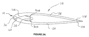
図3Aおよび3Bは、先行する実施形態と同様であるが、マスト28が閉形態にある剛性翼10内に位置する剛性翼型帆10の別の実施形態を表している。参照を容易にするため、また繰り返しを避けるために、この実施形態の類似の構成要素は、先行する好ましい実施形態と同一の参照符号で示されている。剛性翼10は、マスト28に沿って長手方向に離間された30Aおよび30Bなどの1対または複数対のストラットを含む。ストラット30Aおよび30Bは、等しくかつ一定の長さを有し、その幾何学的形状がパネル12A/Bの互いに対する開閉に適するように、ヒンジ要素14のシャフト26に対する所定の位置でそれぞれのパネル12Aおよび12Bに接続される。ストラット30A/Bは、互いに対向する端部をマスト28と翼12Aまたは12Bとにそれぞれ枢動可能に接続する。剛性翼型帆10の前縁部から後方に離間されたマスト28を伴って、剛性翼型帆10は、閉形態および開形態にあるときにバランスが保たれる。
3A and 3B represent another embodiment of a
図4A〜図4Cは、本発明による剛性翼10の更なる実施形態を図示している。剛性翼10のこの変形形態は、追加のパネル34Aおよび34Bを含むことを除いて先行する実施形態と基本的に同一である。これらの追加のパネル34A/Bは、細長い1次パネル12A/Bのそれぞれに枢動可能に接続される。追加のパネル、すなわち2次パネル34A/Bは、閉形態にある剛性翼10の内側に畳まれる。繰り返しを避けるため、また参照を容易にするために、この実施形態の類似の構成要素は、先行する実施形態と同一の参照符号で表示されている。
4A-4C illustrate a further embodiment of a
2次パネル34A/Bは、一体の剛性材料から作られる。2次パネルは各々、開形態では、剛性翼10が1次パネル12A/Bの連続部を形成するように湾曲している。図4Cは、この更なる実施形態の剛体翼10の段階的な開閉を図示している。これらの2次パネルは、翼型帆の基部における関節機構により駆動および制御される。
The
図5Aおよび図5Bは、本発明による剛性翼の更に別の実施形態を図示している。剛性翼のこの変形形態は、細長いパネル12Aおよび12Bのそれぞれに連結された1対のシャフト36Aおよび36Bを含む。シャフト36A/Bは、この代替的な実施形態では、それぞれのパネル12A/Bが開閉するために枢動する1対のマストの形態である。参照を容易にするために、この実施形態の類似の構成要素は、先行する実施形態と同一の参照符号で表示されている。
5A and 5B illustrate yet another embodiment of a rigid wing according to the present invention. This variation of the rigid wing includes a pair of shafts 36A and 36B coupled to each of the
図6は、12Aおよび12Bなどのパネルの枢動を駆動するためのヒンジの作動手段の実施形態を表している。40として示されているヒンジ作動手段は、パネル12A/Bの互いに対する枢動のためのヒンジ要素14に動作可能に連結される。図1〜図4の剛性翼型帆10について、ヒンジ作動手段40は、それぞれの1次パネル12Aおよび12Bの枢動を駆動するように配設された1対の同軸駆動シャフト42および44を含む。この実施形態では、駆動シャフト42および44を、パネル12A/Bまたはそれぞれの管状セグメント22a、22aのいずれかに直接固定することができる。代替的に、駆動シャフト42および44を、例えば、中間歯車(図示せず)を介して、細長いパネル12A/Bに間接的に連結することができる。この例では、作動手段40は、駆動シャフト48に連結された電気モータ(図示せず)により駆動される、45および46として示されている歯車列を含む。
FIG. 6 represents an embodiment of the actuating means of the hinge for driving the pivoting of panels such as 12A and 12B. A hinge actuating means, indicated as 40, is operably connected to the
図5の代替的な実施形態において、駆動シャフト42および44は、それぞれのシャフトまたはマスト36A、36Bと整列するまたは独立に協働するように互いに軸方向に離間される。いずれにしても、ヒンジ作動手段40は、シャフト42および44の互いに逆方向の回転をもたらす適切な歯車装置を介して駆動シャフト42および44の両方に連結された駆動モータを含む。代替的に、ヒンジ作動手段は、駆動シャフト42および44のそれぞれに連結された1対の駆動モータを含むことができる。
In the alternative embodiment of FIG. 5, the
図7A〜図7Cは、10などの剛性翼型帆の昇降のための関節機構49の一例を示している。マスト28が下げられたときに、剛性パネルをa)閉じ、甲板上で一方側にまたは別の側に折り畳む(図7Aを参照)、b)閉じ、船舶の上部構造51および船体内に収納する(図7Bを参照)、c)開き、相補的な形状を有するように設計された船舶55の上部構造53に巻き付ける(図7Cを参照)、d)開き、「オーニング」として水平に保管する(図示せず)ことができる。
7A-7C show an example of a joint mechanism 49 for raising and lowering a rigid winged sail such as 10. FIG. When the
この実施形態において、剛性翼10は、傾動台50に取り付けられたマスト26を含む。傾動台50は、水上船舶(図示せず)の例えば甲板に取り付けられるように設計された台座52に枢動可能に接続する。閉形態にある剛性翼10を、図7Bに示すように、剛性翼10が下げられたときに甲板よりも上または下に位置するカセットまたは区画室54内に収容することもできる。
In this embodiment, the
傾動台50は、この実施形態では、互いに対向する端部が台座52の基部と傾動台50とに接続された56Aおよび56Bなどの1つまたは複数の油圧シリンダを介して傾動させる。したがって、好ましくは閉形態にある剛性翼10の昇降のために、傾動台50を台座52に対して枢動させる。代替的に、甲板よりも上に取り付けられた台座52、剛性翼10が日差しを遮る開形態に剛性翼10を下げることができる。
In this embodiment, the tilting table 50 is tilted via one or a plurality of hydraulic cylinders such as 56A and 56B whose ends facing each other are connected to the base of the
加えて、12Aおよび12Bなどの細長いパネルの一方または両方の好ましくは凸面上において、剛性翼型帆10をソーラーパネル(図示せず)で被覆するまたは部分的に覆うことができる。ソーラーパネルは、剛性翼10にわたって帯板状に引き出されるパネルなどの、太陽光発電(PV)パネルの形態をとることができる。発電するためにソーラーパネルを使用することができ、その電力は、船舶(図示せず)の補助装置を駆動または支持するのを助けるために利用される。
In addition, the
本発明のいくつかの好ましい実施形態について説明してきたので、剛性翼が少なくとも以下の利点を有することは当業者には明らかであろう。1)閉形態にパネルを枢動させることにより、剛性翼の面積を低減するまたは剛性翼を効果的に縮帆することができる。2)翼のキャンバーを効果的に再形成する/変化させるためにパネルの相対的配置をずらすことにより風を効果的に捉えるように、剛体翼を再構成することができる。3)剛性翼は、i)効果的な操作のために見掛けの風に対して剛性翼の角度を変化させる旋回運動、および/またはii)例えば、取り付けられる船舶上にまたは船舶内に効果的に収納するために、昇降させるための剛性翼の傾動を可能にする取付装置に適している。4)好ましい形態における剛性翼は、比較的単純で安価な製造に適する各々一体構成の1対の細長いパネルを含む。 Having described several preferred embodiments of the present invention, it will be apparent to those skilled in the art that rigid wings have at least the following advantages. 1) By pivoting the panel to the closed configuration, the area of the rigid wing can be reduced or the rigid wing can be effectively contracted. 2) Rigid wings can be reconfigured to effectively capture the wind by shifting the relative arrangement of the panels to effectively reshape / change the wing camber. 3) Rigid wings i) swivel motion that changes the angle of the rigid wings relative to the apparent wind for effective operation, and / or ii) effectively, for example, on or in a vessel to be installed It is suitable for a mounting device that allows tilting of a rigid wing for raising and lowering for storage. 4) The rigid wing in the preferred form includes a pair of elongated panels, each in a single piece, suitable for relatively simple and inexpensive manufacture.
当業者は、本明細書で説明した発明が、特に説明したもの以外の変形形態および修正形態が受け入れられ得ることを認識するであろう。例えば、ヒンジ作動手段は、説明した機械的装置から逸脱することができ、ヒンジ作動手段を、例えば、油圧または空気圧により駆動することができる。剛性翼の細長いパネルは、翼形部を提供するために必ずしも好ましい実施形態に従って成形される必要はなく、それらの最も単純な形態では平面パネルに限定される可能性がある。剛性翼およびパネルが主に剛性材料から製造されるのであれば、構成材料もまた、説明した材料から逸脱することができる。剛性翼は、水上船舶での用途に限定されるものではなく、飛行船、宇宙船、陸上用の船、および砕氷船などの他の用途にも及ぶことができる。 Those skilled in the art will recognize that the invention described herein is susceptible to variations and modifications other than those specifically described. For example, the hinge actuating means can deviate from the described mechanical device, and the hinge actuating means can be driven, for example, hydraulically or pneumatically. The rigid wing elongated panels do not necessarily have to be shaped according to the preferred embodiment to provide an airfoil, and in their simplest form may be limited to flat panels. If the rigid wings and panels are made primarily from rigid materials, the construction materials can also deviate from the described materials. Rigid wings are not limited to use on surface ships, but can extend to other uses such as airships, spacecraft, land-based ships, and icebreakers.
全てのこのような変形形態および修正形態は、本発明の範囲内にあると見なされるべきであり、本発明の本質は、前述の説明から決定されるべきである。 All such variations and modifications are to be considered within the scope of the invention, and the essence of the invention should be determined from the foregoing description.
Claims (15)
側縁部に対向する隣接縁部を各々有する1対の細長い剛性パネルであって、前記1対の細長い剛性パネルの前記隣接縁部が細長い孔を画定する剛性パネルと、
前記1対の細長い剛性パネルに前記剛性パネルの隣接縁部で連結されるマストを含み、前記剛性パネルの互いに対する枢動であって、前記マストを中心とした枢動を可能にし、
i)前記剛性パネルの前記側縁部が互いに隣接する閉形態であって、前記剛性翼型帆が実質的に閉じられる前記閉形態、
または
ii)前記細長い剛性パネルの前記側縁部が互いに隔てられる種々の開形態であって、前記剛性パネルの相対的配置をずらすことにより前記剛性翼型帆のキャンバーを再形成しかつ変化させて風を効果的に捉えるように、前記剛性翼型帆が可変キャンバーとされる前記開形態、
のいずれかを形成するヒンジ要素と、
を備え、
前記マストは、前記細長い孔に受け入れられ、前記閉形態および前記種々の開形態において前記1対の剛性パネルの前記隣接縁部に位置する、
剛性翼型帆。 A rigid wing sail,
A pair of elongate rigid panels each having an adjacent edge opposite the side edges, wherein the adjacent edge of the pair of elongate rigid panels defines an elongated hole;
Including a mast coupled to the pair of elongate rigid panels at adjacent edges of the rigid panel, wherein the rigid panels pivot relative to each other, allowing pivoting about the mast;
i) a closed configuration in which the side edges of the rigid panel are adjacent to each other, wherein the rigid wing sail is substantially closed;
Or ii) various open configurations in which the side edges of the elongate rigid panel are separated from each other, by reshaping and changing the rigid wing sail camber by shifting the relative arrangement of the rigid panels The open configuration in which the rigid winged sail is a variable camber so as to effectively capture the wind,
A hinge element forming any of
With
The mast is received in the elongated hole and is located at the adjacent edge of the pair of rigid panels in the closed configuration and the various open configurations;
Rigid wing sail.
請求項1に記載の剛性翼型帆。 The hinge element is in the form of a piano hinge that forms the elongated hole,
The rigid wing sail according to claim 1.
請求項1に記載の剛性翼型帆。 The mast is attached to an articulation mechanism that allows the mast to tilt, and thus the rigid wing sail including the mast, can be raised and lowered.
The rigid wing sail according to claim 1.
請求項1に記載の剛性翼型帆。 A solar concentrator attached or affixed to at least an exposed surface of the pair of elongated rigid panels;
The rigid wing sail according to claim 1.
請求項1に記載の剛性翼型帆。 Each of the pair of rigid panels is one continuous piece of rigid material;
The rigid wing sail according to claim 1.
請求項1に記載の剛性翼型帆。 Each of the pair of rigid panels is a curved panel having an asymmetric cross-sectional shape.
The rigid wing sail according to claim 1.
請求項6に記載の剛性翼型帆。 The pair of asymmetric panels have substantially the same outer shape and cross-sectional shape;
The rigid wing type sail according to claim 6.
請求項7に記載の剛性翼型帆。 The rigid wing sail of the variable camber is symmetrical on both sides of the hinge element;
The rigid wing type sail according to claim 7.
前記2次剛性パネルは、種々の開形態では前記剛性パネルの連続部を形成し、前記剛性翼型帆の閉形態では前記剛性翼型帆の内側に畳まれるように配設される、
請求項1に記載の剛性翼型帆。 A pair of secondary rigid panels that are elongated and each pivotally connected to each of the pair of rigid panels at a side edge of the rigid panel;
The secondary rigid panel forms a continuous portion of the rigid panel in various open configurations, and is arranged to be folded inside the rigid wing sail in the closed configuration of the rigid wing sail.
The rigid wing sail according to claim 1.
請求項1に記載の剛性翼型帆。 A hinge actuation mechanism operably coupled to the hinge elements for pivoting the rigid panels relative to each other;
The rigid wing sail according to claim 1.
請求項10に記載の剛性翼型帆。 The hinge actuation mechanism includes one or more gears operably coupled to at least one of the elongated rigid panel and the hinge element;
The rigid wing sail according to claim 10.
請求項1に記載の剛性翼型帆。 Rotating means operably coupled to the mast so as to allow the mast to pivot about a longitudinal axis of the mast to orient the rigid wing sail at a required angle with respect to the wind Further comprising
The rigid wing sail according to claim 1.
請求項10に記載の剛性翼型帆。 The hinge actuation mechanism includes swiveling means configured to orient the rigid wing sail at a required angle with respect to the wind;
The rigid wing sail according to claim 10.
請求項1に記載の剛性翼型帆。 Made to fit the vehicle,
The rigid wing sail according to claim 1.
請求項14に記載の剛性翼型帆。
The vehicle is a surface vessel;
The rigid wing sail according to claim 14.
Applications Claiming Priority (3)
| Application Number | Priority Date | Filing Date | Title |
|---|---|---|---|
| AU2012904360A AU2012904360A0 (en) | 2012-10-05 | Opening Rigid Wing | |
| AU2012904360 | 2012-10-05 | ||
| PCT/AU2013/001153 WO2014053029A1 (en) | 2012-10-05 | 2013-10-08 | Opening rigid wing |
Publications (3)
| Publication Number | Publication Date |
|---|---|
| JP2015530314A JP2015530314A (en) | 2015-10-15 |
| JP2015530314A5 JP2015530314A5 (en) | 2016-11-24 |
| JP6346185B2 true JP6346185B2 (en) | 2018-06-20 |
Family
ID=50434336
Family Applications (1)
| Application Number | Title | Priority Date | Filing Date |
|---|---|---|---|
| JP2015534884A Active JP6346185B2 (en) | 2012-10-05 | 2013-10-08 | Expanded rigid wing |
Country Status (9)
| Country | Link |
|---|---|
| US (2) | US9527563B2 (en) |
| EP (1) | EP2903890B1 (en) |
| JP (1) | JP6346185B2 (en) |
| CN (1) | CN104736430B (en) |
| AU (2) | AU2013327408B2 (en) |
| CA (1) | CA2886047C (en) |
| NZ (2) | NZ726059A (en) |
| WO (1) | WO2014053029A1 (en) |
| ZA (1) | ZA201502989B (en) |
Families Citing this family (14)
| Publication number | Priority date | Publication date | Assignee | Title |
|---|---|---|---|---|
| EP2903890B1 (en) * | 2012-10-05 | 2017-11-29 | Solar Sailor Pty. Ltd. | Opening rigid wing |
| US10293904B2 (en) * | 2016-05-13 | 2019-05-21 | Wind + Wing Technologies, Inc. | Deployable wingsail for container ships |
| US10870472B2 (en) | 2016-05-13 | 2020-12-22 | Wind + Wing Technologies, Inc. | Deployable wingsail for container ships |
| CN111727152B (en) | 2018-02-02 | 2023-02-17 | M·弗雷泽 | Sail |
| US10526096B2 (en) * | 2018-05-20 | 2020-01-07 | Subseasail LLC | Solar wing system and apparatus |
| CN109204750B (en) * | 2018-11-07 | 2020-06-16 | 西北工业大学 | Paddle type propelling and gliding mechanism of underwater vehicle |
| CN109204751B (en) * | 2018-11-07 | 2020-05-12 | 西北工业大学 | Underwater vehicle paddle type propelling and gliding mechanism based on water resistance free folding |
| DE202019102941U1 (en) | 2019-02-18 | 2019-06-05 | Becker Marine Systems Gmbh | Fixed sails for watercraft, in particular for large ships, and watercraft with rigid sails |
| FR3103781B1 (en) * | 2019-11-28 | 2022-06-03 | Cws Morel | Propulsion wing of a moving machine, and moving machine comprising such a propulsion wing. |
| FR3106566B1 (en) * | 2020-01-29 | 2024-04-05 | Inno&Sokol | Electricity production installation for ships |
| CN113772068B (en) * | 2021-08-31 | 2022-11-11 | 武汉理工大学 | Wing type sail navigation aid capable of transversely opening |
| CN113815792A (en) * | 2021-09-03 | 2021-12-21 | 中山大学 | Intelligent unmanned aircraft with strong survival force and long period |
| FR3132694B1 (en) | 2022-02-17 | 2024-02-02 | Ship Studio Sarl | Rigid sails for a ship, laid on the cob |
| FR3132693B1 (en) | 2022-02-17 | 2024-02-02 | Ship Studio Sarl | Pivoting spreader for a rigid sail |
Family Cites Families (28)
| Publication number | Priority date | Publication date | Assignee | Title |
|---|---|---|---|---|
| GB1410175A (en) | 1971-12-18 | 1975-10-15 | Wainwright B | Aerofoils and hydrofoils |
| US3934533A (en) * | 1973-09-12 | 1976-01-27 | Barry Wainwright | Aerofoil or hydrofoil |
| JPS6223509Y2 (en) * | 1980-02-09 | 1987-06-15 | ||
| US4418632A (en) | 1981-04-28 | 1983-12-06 | Nippon Kokan Kabushiki Kaisha | Method for operating a rigid marine sail |
| JPS5833591A (en) * | 1981-07-03 | 1983-02-26 | バリ−・ワインライト | Aerofoil |
| US4505217A (en) * | 1982-05-14 | 1985-03-19 | Nippon Kokan Kabushiki Kaisha | Rigid marine sail |
| JPS6117400U (en) * | 1984-07-06 | 1986-01-31 | 三菱重工業株式会社 | sailing boat |
| JPS61200092A (en) * | 1985-02-28 | 1986-09-04 | Osaka Sosenjo:Kk | Hard sail device for ship |
| US4655154A (en) * | 1986-01-27 | 1987-04-07 | Leonard James B | Collapsible mast assembly |
| IT1217147B (en) * | 1987-03-27 | 1990-03-14 | Barberis Michele | DEVICE SUITABLE FOR AVOIDING THE TILTING OF CATAMARANS |
| DE3836259A1 (en) * | 1988-10-25 | 1990-04-26 | Kranert Klaus | Solar-powered sailing yacht |
| GB2234723A (en) | 1989-06-22 | 1991-02-13 | James Harwood Crafer | Stowable rigid wingsail system |
| DE9004412U1 (en) * | 1990-04-18 | 1990-09-13 | Wiese, Andreas, 5300 Bonn, De | |
| JPH05310189A (en) * | 1992-04-30 | 1993-11-22 | Shinichi Inabe | Wing-shaped ship sail covered with solar cell |
| DE4224427C2 (en) * | 1992-07-24 | 1995-11-02 | Keiper Recaro Gmbh Co | Emergency seat for vehicles, in particular motor vehicles |
| JP3050016U (en) * | 1997-10-31 | 1998-06-30 | 信一 稲部 | Wing-shaped ship sail covered with solar fields |
| RU2148524C1 (en) | 1999-10-21 | 2000-05-10 | Кульбида Владимир Евгеньевич | Multipurpose sail system and method of its operation |
| US6431100B2 (en) * | 2000-03-24 | 2002-08-13 | Charles Allen Abshier | Stowable semi-rigid wing sail system |
| JP3075476U (en) * | 2000-08-08 | 2001-02-23 | 光男 池田 | Non-water windsurfing |
| US6525861B1 (en) * | 2001-12-10 | 2003-02-25 | Gentex Corporation | Electrochromic device having a current-reducing additive |
| JP2004161224A (en) * | 2002-11-11 | 2004-06-10 | Yutaka Oguri | Wind force propulsion device |
| US7789723B2 (en) * | 2003-07-31 | 2010-09-07 | Solar Sailor Pty Ltd | Unmanned ocean vehicle |
| US7461609B1 (en) * | 2007-02-14 | 2008-12-09 | Harbor Wing Technologies, Inc. | Apparatus for control of pivoting wing-type sail |
| US7568442B2 (en) * | 2007-04-09 | 2009-08-04 | Alan William Kruppa | Three degree-of-freedom pivot assembly, sail-mounted ballast, and sail control system for high speed sailboats |
| JP5202454B2 (en) * | 2009-07-02 | 2013-06-05 | ホンダ・パテンツ・アンド・テクノロジーズ・ノース・アメリカ・エルエルシー | Molding method for long shaped products |
| CN101920777B (en) * | 2010-09-15 | 2012-07-04 | 武汉理工大学 | Wing sail and ship with same |
| JP5828409B2 (en) * | 2010-10-26 | 2015-12-02 | エコマリンパワー株式会社 | Ship power module and wind power propulsion ship equipped with the ship power module |
| EP2903890B1 (en) * | 2012-10-05 | 2017-11-29 | Solar Sailor Pty. Ltd. | Opening rigid wing |
-
2013
- 2013-10-08 EP EP13843476.6A patent/EP2903890B1/en not_active Not-in-force
- 2013-10-08 NZ NZ726059A patent/NZ726059A/en unknown
- 2013-10-08 WO PCT/AU2013/001153 patent/WO2014053029A1/en active Application Filing
- 2013-10-08 CN CN201380051244.6A patent/CN104736430B/en not_active Expired - Fee Related
- 2013-10-08 CA CA2886047A patent/CA2886047C/en not_active Expired - Fee Related
- 2013-10-08 JP JP2015534884A patent/JP6346185B2/en active Active
- 2013-10-08 AU AU2013327408A patent/AU2013327408B2/en active Active
- 2013-10-08 US US14/432,691 patent/US9527563B2/en active Active
- 2013-10-08 NZ NZ707373A patent/NZ707373A/en not_active IP Right Cessation
-
2015
- 2015-04-30 ZA ZA2015/02989A patent/ZA201502989B/en unknown
-
2016
- 2016-11-02 US US15/341,899 patent/US9937987B2/en active Active
- 2016-11-03 AU AU2016253637A patent/AU2016253637B2/en active Active
Also Published As
| Publication number | Publication date |
|---|---|
| EP2903890A4 (en) | 2016-08-17 |
| CN104736430A (en) | 2015-06-24 |
| ZA201502989B (en) | 2017-04-26 |
| JP2015530314A (en) | 2015-10-15 |
| EP2903890A1 (en) | 2015-08-12 |
| NZ707373A (en) | 2017-02-24 |
| AU2016253637B2 (en) | 2018-01-18 |
| CA2886047C (en) | 2020-04-14 |
| EP2903890B1 (en) | 2017-11-29 |
| US20150266555A1 (en) | 2015-09-24 |
| CA2886047A1 (en) | 2014-04-10 |
| WO2014053029A1 (en) | 2014-04-10 |
| AU2016253637A1 (en) | 2016-12-01 |
| NZ726059A (en) | 2017-12-22 |
| US20170066517A1 (en) | 2017-03-09 |
| CN104736430B (en) | 2017-11-24 |
| US9937987B2 (en) | 2018-04-10 |
| US9527563B2 (en) | 2016-12-27 |
| AU2013327408A1 (en) | 2015-05-14 |
| AU2013327408B2 (en) | 2016-09-29 |
Similar Documents
| Publication | Publication Date | Title |
|---|---|---|
| JP6346185B2 (en) | Expanded rigid wing | |
| US6105524A (en) | Pivoting sailing rig | |
| US4402277A (en) | Aerofoil sail | |
| WO2012057178A1 (en) | Power module for use in marine vessel, and wind-propelled vessel provided with said power module | |
| US20060118020A1 (en) | Reversible camber airfoil | |
| EP3538432B1 (en) | Ship with sail propulsion | |
| CN111094125A (en) | Propeller pump type hydraulic propulsion device and ship equipped with such a device | |
| EP4219287A1 (en) | Wingsail structure for a wind-assisted propulsion arrangement of a marine vessel | |
| JP7493037B2 (en) | Propulsion Device | |
| JP7480297B2 (en) | Propulsion blade of a moving medium and a moving medium equipped with such a propulsion blade | |
| EP4303115A1 (en) | Wingsail structure for a wind-assisted propulsion arrangement for a marine vessel | |
| GB2110622A (en) | Hybrid sail apparatus | |
| EP4382410A1 (en) | Wingsail structure for wind-assisted propulsion of a marine vessel | |
| GB2088308A (en) | Aerofoil sail | |
| KR20240000932U (en) | Energy saving apparatus for container ship using ground effect | |
| AU717925B2 (en) | A pivoting sailing rig | |
| WO2024120931A1 (en) | Wingsail structure for wind-assisted propulsion of a marine vessel | |
| FR2792283A1 (en) | Rigid sail for boats, merchant ships and land and ice yachts has thick profile sections mounted in rectangular mast which can be inverted by pivoting through half-turn like venetian blind | |
| WO2020234456A1 (en) | Sail | |
| FR2558790A1 (en) | Sail propulsion device | |
| FR2720368A1 (en) | Multi-hulled boat with adjustable floats | |
| JPS58183383A (en) | Sail | |
| PL225325B1 (en) | Ecological solar sail propulsion with rigid wind active propellers, assisted by a generating set |
Legal Events
| Date | Code | Title | Description |
|---|---|---|---|
| A521 | Request for written amendment filed |
Free format text: JAPANESE INTERMEDIATE CODE: A523 Effective date: 20161005 |
|
| A621 | Written request for application examination |
Free format text: JAPANESE INTERMEDIATE CODE: A621 Effective date: 20161005 |
|
| A977 | Report on retrieval |
Free format text: JAPANESE INTERMEDIATE CODE: A971007 Effective date: 20170814 |
|
| A131 | Notification of reasons for refusal |
Free format text: JAPANESE INTERMEDIATE CODE: A131 Effective date: 20170905 |
|
| A521 | Request for written amendment filed |
Free format text: JAPANESE INTERMEDIATE CODE: A523 Effective date: 20171205 |
|
| TRDD | Decision of grant or rejection written | ||
| A01 | Written decision to grant a patent or to grant a registration (utility model) |
Free format text: JAPANESE INTERMEDIATE CODE: A01 Effective date: 20180508 |
|
| A61 | First payment of annual fees (during grant procedure) |
Free format text: JAPANESE INTERMEDIATE CODE: A61 Effective date: 20180524 |
|
| R150 | Certificate of patent or registration of utility model |
Ref document number: 6346185 Country of ref document: JP Free format text: JAPANESE INTERMEDIATE CODE: R150 |
|
| R250 | Receipt of annual fees |
Free format text: JAPANESE INTERMEDIATE CODE: R250 |
|
| R250 | Receipt of annual fees |
Free format text: JAPANESE INTERMEDIATE CODE: R250 |
|
| R250 | Receipt of annual fees |
Free format text: JAPANESE INTERMEDIATE CODE: R250 |