JP6344294B2 - Sheet feeding device and image forming apparatus having sheet feeding device - Google Patents
Sheet feeding device and image forming apparatus having sheet feeding device Download PDFInfo
- Publication number
- JP6344294B2 JP6344294B2 JP2015080966A JP2015080966A JP6344294B2 JP 6344294 B2 JP6344294 B2 JP 6344294B2 JP 2015080966 A JP2015080966 A JP 2015080966A JP 2015080966 A JP2015080966 A JP 2015080966A JP 6344294 B2 JP6344294 B2 JP 6344294B2
- Authority
- JP
- Japan
- Prior art keywords
- paper
- sheet
- path
- cassette
- sensor
- Prior art date
- Legal status (The legal status is an assumption and is not a legal conclusion. Google has not performed a legal analysis and makes no representation as to the accuracy of the status listed.)
- Expired - Fee Related
Links
Images


Description
本発明は、給紙装置および給紙装置を備える画像形成装置に関し、特に、給紙カセットに収容された用紙を検出する技術に関する。 The present invention relates to a sheet feeding device and an image forming apparatus including the sheet feeding device, and more particularly to a technique for detecting a sheet stored in a sheet feeding cassette.
コピー機、プリンター、ファクシミリ装置、および複合機等の画像形成装置では、給紙される用紙のサイズに合わせて画像の形成を行うため、給紙カセットに収容された用紙のサイズを正しく検出しておくことが必要となる。例えば、特許文献1には、給紙カセットの底部に複数の検出スイッチを設け、当該検出スイッチから出力される検出信号に基づき、給紙カセットに収容された用紙のサイズを検出する技術が開示されている。
In image forming apparatuses such as copiers, printers, facsimile machines, and multifunction machines, images are formed according to the size of the paper to be fed. Therefore, the size of the paper stored in the paper cassette is detected correctly. It is necessary to keep it. For example,
しかしながら、給紙カセットに収容された用紙束に複数のサイズの用紙が混在している場合、上記の特許文献1に記載される技術を用いたとしても、給紙カセットに収容された用紙のサイズを正しく検出することができない。このため、画像形成装置は、画像を正しく形成することができない。
However, in the case where a plurality of sizes of paper are mixed in the paper bundle accommodated in the paper feed cassette, the size of the paper accommodated in the paper feed cassette can be obtained even if the technique described in
また、画像形成装置は、給紙カセットに収容された用紙が折れ曲がっている場合等でも画像を正しく形成することができない。このため、上記の特許文献1に記載される技術を用いたとしても、このような用紙の折れ曲がりを検出することができない。
Further, the image forming apparatus cannot correctly form an image even when the paper stored in the paper feed cassette is bent. For this reason, even if the technique described in
すなわち、上記の特許文献1に記載される技術では、画像形成の品質に影響を及ぼす不適切な用紙の有無を検出することができない。本発明は、上記の事情に鑑みなされたものであり、給紙カセットに収容された用紙束に含まれる不適切な用紙を検出することを可能にすることを目的とする。
In other words, the technique described in the above-mentioned
本発明の一局面にかかる給紙装置は、給紙カセットと、前記給紙カセットに収容された用紙束から1枚ずつ用紙を給紙するローラーと、前記給紙カセットの上方に設置され、超音波を前記用紙束の上面に向けて発振するとともに当該用紙束の上面で反射した超音波を受信して、当該受信した超音波に応じた出力信号を出力する2つの超音波センサーと、前記2つの超音波センサーのうち、一方の超音波センサーを前記給紙カセットの上方に設けられた第1の経路で移動させ、他方の超音波センサーを前記給紙カセットの上方に設けられた第2の経路で移動させる移動機構と、前記移動機構が前記2つの超音波センサーを移動させている間に前記2つの超音波センサーから出力される出力信号に基づき、前記用紙束内の不適切な用紙の有無を判定する判定部と、前記判定部が不適切な用紙有りと判定した場合に、前記ローラーによる給紙動作を停止させる制御を行う動作制御部と、を備える給紙装置である。 A sheet feeding device according to one aspect of the present invention is provided above a sheet feeding cassette, a roller that feeds sheets one by one from a sheet bundle accommodated in the sheet feeding cassette, Two ultrasonic sensors that oscillate sound waves toward the upper surface of the sheet bundle, receive ultrasonic waves reflected by the upper surface of the sheet bundle, and output an output signal corresponding to the received ultrasonic waves; Of the two ultrasonic sensors, one ultrasonic sensor is moved along a first path provided above the paper cassette, and the other ultrasonic sensor is a second sensor provided above the paper cassette. A moving mechanism that moves along a path, and an output signal output from the two ultrasonic sensors while the moving mechanism moves the two ultrasonic sensors. Presence or absence A determination unit that, if the previous SL determination unit determines that there is improper paper, a sheet feeding apparatus and an operation control unit which performs control to stop the feeding operation by the roller.
また、本発明の別の一局面にかかる画像形成装置は、上記の給紙装置と、上記の給紙装置から給紙された用紙に画像を形成する画像形成部と、を備える画像形成装置である。 An image forming apparatus according to another aspect of the present invention is an image forming apparatus that includes the paper feeding device and an image forming unit that forms an image on paper fed from the paper feeding device. is there.
本発明によれば、給紙カセットに収容された用紙束に含まれる不適切な用紙を検出することができる。 According to the present invention, it is possible to detect inappropriate paper contained in a paper bundle stored in a paper feed cassette.
以下、本発明の一実施形態にかかる給紙装置、および当該給紙装置を備える画像形成装置について図面を参照して説明する。 Hereinafter, a sheet feeding device according to an embodiment of the present invention and an image forming apparatus including the sheet feeding device will be described with reference to the drawings.
図1は、本発明の一実施形態にかかる画像形成装置の構造を示す断面図である。画像形成装置1は、例えば、コピー機能、プリンター機能、スキャナー機能、およびファクシミリ機能等の複数の機能を兼ね備えた複合機である。画像形成装置1は、装置本体11内に、原稿読取部5、原稿給送部6、画像形成部12、定着部13、および給紙部14等を備えて構成されている。
FIG. 1 is a sectional view showing the structure of an image forming apparatus according to an embodiment of the present invention. The
画像形成装置1が原稿読取動作を行う場合、原稿給送部6により給送されてくる原稿、又は原稿載置ガラス161に載置された原稿の画像を原稿読取部5が光学的に読み取り、画像データを生成する。
When the
画像形成装置1が画像形成動作を行う場合、原稿読取動作により生成された画像データやネットワーク接続されたコンピューターから受信した画像データ等に基づいて、画像形成部12が、給紙部14から給紙される記録媒体としての用紙Pにトナー画像を形成する。
When the
画像形成部12の画像形成ユニット12M、12C、12Y、及び12Bkは、それぞれ、感光体ドラム121、現像装置122、帯電装置123、露光装置124、および1次転写ローラー126を備え、帯電、露光及び現像の工程により感光体ドラム121上にトナー画像を形成する。当該トナー画像は、1次転写ローラー126により駆動ローラー125A及び従動ローラー125Bに張架されている中間転写ベルト125上に転写される。
The
中間転写ベルト125上に転写される各色のトナー画像は、転写タイミングを調整して中間転写ベルト125上で重ね合わされ、カラーのトナー画像となる。2次転写ローラー210は、中間転写ベルト125の表面に形成されたカラーのトナー画像を、中間転写ベルト125を挟んで駆動ローラー125Aとのニップ部Nにおいて、給紙部14から搬送路190を搬送されてきた用紙Pに転写させる。この後、定着部13が用紙P上のトナー画像を熱圧着により用紙Pに定着させる。定着処理の完了したカラー画像形成済みの用紙Pは、排出トレイに排出される。
The toner images of the respective colors transferred onto the
次に、画像形成装置1の内部構成を説明する。図2は、画像形成装置1の主要内部構成を示す機能ブロック図である。
Next, the internal configuration of the
画像形成装置1は、既述の原稿読取部5、原稿給送部6、画像形成部12、定着部13、および給紙部14等に加えて、画像メモリー32、操作部47、記憶部92、および制御ユニット10等を備えている。
The
画像メモリー32は、原稿読取部5による読取で得られた画像データや画像形成部12の画像形成対象となる画像データを一時的に保存する領域である。
The
操作部47は、画像形成装置1が実行可能な各種動作や処理についてユーザーからの指示を受け付けるタッチパネル部や物理キー等を備える。当該タッチパネル部は、タッチパネルが設けられたLCD(Liquid Crystal Display)等の表示部473を備えてなる。
The
記憶部92は、HDD(Hard Disk Drive)等の大容量の記憶装置である。
The
制御ユニット10は、CPU(Central Processing Unit)、RAM(Random Access Memory)、およびROM(Read Only Memory)等から構成される。制御ユニット10は、上記のROMまたは記憶部92に記憶された制御プログラムが上記のCPUに実行されることにより、動作制御部100、センサー制御部101、判定部102、および報知制御部103として機能する。なお、制御ユニット10の動作制御部100、センサー制御部101、判定部102、および報知制御部103は、上記の制御プログラムに基づく動作によらず、それぞれハード回路により構成されてもよい。
The
動作制御部100は、原稿読取部5、原稿給送部6、画像形成部12、給紙部14、画像メモリー32、操作部47、および記憶部92等と接続されており、接続されている上記各機構の動作制御や、各機構との間での信号又はデータの送受信を行う。特に、動作制御部100は、給紙部14による給紙動作を制御する機能を有する。
The
センサー制御部101は、給紙部14内に設置された後述する第1センサー145および第2センサー146の移動動作を制御する機能を有する。
The
判定部102は、第1センサー145および第2センサー146から出力される出力信号に基づき、画像形成部12による画像形成の品質に影響を及ぼす不適切な用紙が給紙部14内の用紙束に含まれているか否かを判定する機能を有する。
Based on the output signals output from the
報知制御部103(報知部)は、判定部102が不適切な用紙が含まれていると判定した場合に、予め定められた警告報知処理を実行する機能を有する。
The notification control unit 103 (notification unit) has a function of executing a predetermined warning notification process when the
本発明の一実施形態にかかる給紙装置は、上記の給紙部14および制御ユニット10等から構成される。以下では、当該給紙装置の詳細な構成を説明する。なお本明細書では、画像形成装置1が備える複数の給紙装置のうち最下段に位置する給紙装置を例に説明する。
A sheet feeding device according to an embodiment of the present invention includes the
図3は、給紙部14の構造を示す斜視図である。図4は、給紙部14の構造を示す断面図である。図3および図4に示すように、給紙部14は、給紙部14の外郭を構成する給紙カセット15を備え、その内部に用紙束P1を収容する。給紙カセット15は、装置本体11に着脱自在に構成される。図1、図3および図4に示す例では、紙面右側(マイナスX方向側)に給紙カセット15を引き出すことができる。
FIG. 3 is a perspective view showing the structure of the
給紙部14は、ピックアップローラー141および搬送ローラー171を備える。ピックアップローラー141は、モーター、ギア、ドライバー等から構成される昇降駆動部142(図2参照)により昇降可能に構成されている。昇降駆動部142によりピックアップローラー141が降下されると、ピックアップローラー141の周面が給紙カセット15に収容された用紙束P1の最上面に当接する。この状態で、ピックアップローラー141が回動することで用紙束P1から1枚ずつ用紙が繰り出される。ピックアップローラー141により繰り出された用紙は、搬送ローラー171により画像形成部12に向けて搬送される。
The
また、給紙部14は、用紙束P1の位置決めを行うために、用紙束P1が載置される載置面151上に、左端規制部材153A、右端規制部材153B、および後端規制部材155が設置されている。左端規制部材153Aおよび右端規制部材153Bは、載置面151上に形成された溝154に沿って、Z方向およびマイナスZ方向にスライド移動可能とされる。また、後端規制部材155は、載置面151上に形成された溝156に沿って、X方向およびマイナスX方向にスライド移動可能とされる。ユーザーにより給紙カセット15内に用紙束P1が収容された後、用紙束P1に当接するように左端規制部材153A、右端規制部材153B、および後端規制部材155をスライド移動されることで、用紙束P1の位置決めが完了する。上記の左端規制部材153A、右端規制部材153B、および後端規制部材155の位置を検知するために、給紙部14には、複数のセンサーからなる規制位置検知部143(図2参照)が設けられている。当該規制位置検知部143から出力される出力信号に基づいて、制御ユニット10の動作制御部100が用紙束P1の用紙サイズを特定する。
Further, in order to position the sheet bundle P1, the
ここで、給紙カセット15の上方(Y方向側)には、用紙束P1の高さを検知する用紙高さ検知部144(図2参照)として、第1センサー145および第2センサー146(図5参照)が設けられている。第1センサー145および第2センサー146はそれぞれ、圧電素子を用いた超音波センサーであって、その主発振方向および主受信方向が下方(マイナスY方向)に向けられている。第1センサー145および第2センサー146は、圧電素子に予め定められた電圧値の電圧を印加することで超音波を発振する。当該発振された超音波は、用紙束P1の上面で反射した後、第1センサー145および第2センサー146で受信される。圧電素子には当該受信した超音波の強度に応じた起電力が発生する。これにより、第1センサー145および第2センサー146は、受信した超音波の強度に応じた出力信号を出力する。
Here, above the paper feed cassette 15 (Y direction side), a
制御ユニット10の判定部102(図2参照)は、当該第1センサー145および第2センサー146から出力される出力信号に基づいて、用紙束P1の上面から第1センサー145および第2センサー146までの距離を特定する。換言すれば、判定部102は、給紙カセット15の載置面151から用紙束P1の上面までの高さを特定する。上記のように圧電素子を用いた超音波センサーは、一般にフォトダイオードを用いた光センサー等と比較して感度が優れている。このため、判定部102は、給紙カセット15の載置面151から用紙束P1の上面までの高さを精度良く特定することができる。
Based on the output signals output from the
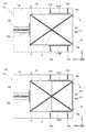
上記の第1センサー145および第2センサー146は、モーター、ギア、ドライバー等から構成されるセンサー駆動部147(図2参照)により、給紙カセット15の上方(Y方向側)に設けられたレール部16上を往復移動する。図5(A)および図5(B)は、給紙部14の構造を示す上面図である。図5(A)および図5(B)に示すように、レール部16は、2本の直線状のレール161、162から構成される。レール161、162は、給紙カセット15の上方(Y方向側)の予め定められた位置Eで交差している。
The
第1センサー145は、不図示の嵌入部がレール161の溝に嵌り込んだ状態で、レール161の一端部である位置Aからレール161の他端部である位置Cまでの間を移動する(図5(A)および図5(B)における矢印参照)。同様に、第2センサー146は、不図示の嵌入部がレール162の溝に嵌り込んだ状態で、レール162の一端部である位置Bからレール162の他端部である位置Dまでの間を移動する(図5(A)および図5(B)における矢印参照)。
The
制御ユニット10の判定部102は、センサー駆動部147が第1センサー145および第2センサー146を移動させている間に第1センサー145および第2センサー146から出力される出力信号に基づき、画像形成部12による画像形成の品質に影響を及ぼす不適切な用紙が用紙束P1に含まれているか否かを判定する。具体的には、判定部102は、第1センサー145および第2センサー146から出力される出力信号に基づき、レール161およびレール162の下方(マイナスY方向側)に位置する用紙束P1の上面の段差の有無を判定する。そして、判定部102は、段差有りと判定する場合に不適切な用紙有りと判定し、段差無しと判定する場合に不適切な用紙無しと判定する。
The
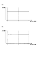
図6(A)および図6(B)は、給紙カセット15に収容される用紙束の一例を示す図である。また、図7(A)は、図6(A)に示す用紙束が給紙カセット15に収容されている場合に、第1センサー145から出力される出力信号の出力値を示すグラフであり、図7(B)は、図6(B)に示す用紙束が給紙カセット15に収容されている場合に、第1センサー145から出力される出力信号の出力値を示すグラフである。
FIGS. 6A and 6B are diagrams illustrating an example of a sheet bundle stored in the
図6(A)に示す例では、A4サイズの用紙からなる用紙束が給紙カセット15に収容されており、用紙束の最上面の用紙がA4サイズの用紙P2になっている。この場合、第1センサー145からは図7(A)に示す出力値の出力信号が出力される。すなわち、第1センサー145が位置Aから位置Cに移動される間、第1センサー145から出力される出力信号の出力値は一定となる。この場合、判定部102は、レール161の下方(マイナスY方向側)に位置する用紙束の上面に段差が無いと判定して、給紙カセット15に収容された用紙束に不適切な用紙が無いと判定する。なお、出力信号の出力値の変動がある場合であっても、その変動値が予め定められた値以下である場合、判定部102は、当該出力値の変動が誤差であると判定して給紙カセット15に収容された用紙束に不適切な用紙が無いと判定する。
In the example shown in FIG. 6A, a sheet bundle made up of A4 size sheets is stored in the
一方、図6(B)に示す例では、A4サイズの用紙からなる用紙束に一枚のA5サイズの用紙が混入しており、用紙束の最上面の用紙がA5サイズの用紙P3になっている。この場合、第1センサー145からは図7(B)に示す出力値の出力信号が出力される。すなわち、第1センサー145が位置Eを通過する際に、第1センサー145から出力される出力信号の出力値が変動する。当該出力値の変動値が予め定められた値より大きい場合、判定部102は、当該出力値の変動を用紙束の上面に存在する段差であると判定して、給紙カセット15に収容された用紙束に不適切な用紙が有ると判定する。
On the other hand, in the example shown in FIG. 6B, a sheet of A5 size is mixed in a sheet bundle of A4 size sheets, and the uppermost sheet of the sheet bundle is A5 size sheet P3. Yes. In this case, the
図8(A)および図8(B)は、給紙カセット15に収容される用紙束の他の一例を示す図である。図8(A)に示す例では、A4サイズの用紙からなる用紙束にA5サイズより小さな用紙が一枚混入しており、用紙束の最上面の用紙が当該小さな用紙P4になっている。この場合、第2センサー146については出力信号の出力値は一定となるが、第1センサー145については位置Fを通過する際に出力信号の出力値が変動する。このため、判定部102は、給紙カセット15に収容された用紙束に不適切な用紙が有ることを判定できる。
FIG. 8A and FIG. 8B are diagrams illustrating another example of the sheet bundle accommodated in the
また、図8(B)に示す例では、用紙束の最上面の用紙P5の一部が折れ曲がっている。この場合、第1センサー145については出力信号の出力値は一定となるが、第2センサー146については、位置Gおよび位置Hを通過する際に出力信号の出力値が変動する。このため、判定部102は、給紙カセット15に収容された用紙束に不適切な用紙が有ることを判定できる。
In the example shown in FIG. 8B, a part of the uppermost sheet P5 of the sheet bundle is bent. In this case, for the
このように、用紙束の高さを検知する構成として、第1センサー145および第2センサー146の2つの超音波センサーを設け、更に、第1センサー145の移動経路である第1の経路と第2センサー146の移動経路である第2の経路とが給紙カセット15の上方(Y方向側)で交差するようにすることで、超音波センサーを1つしか設けない構成や、給紙カセットの底部に複数の検出スイッチを設けた一般の構成と比較して、用紙束の上面における広い範囲で段差の有無を検知することができるため、上記のように用紙束に小さな用紙が混入している場合や用紙が折れ曲がっている場合であっても、不適切な用紙の有無を判定することができる。
As described above, as a configuration for detecting the height of the sheet bundle, two ultrasonic sensors, the
なお、第1センサー145および第2センサー146の移動経路は、必ずしも上記で説明した移動経路に限定されない。第1センサー145の移動経路を位置Aから位置Eを通って位置Dに繋がる移動経路とし、第2センサー146の移動経路を位置Bから位置Eを通って位置Cに繋がる移動経路としてもよい(図5(A)および図5(B)参照)。このような移動経路を採用した場合であっても、用紙束の上面における広い範囲で段差の有無を検知することができるため、上記と同様に用紙束に小さな用紙が混入している場合や用紙が折れ曲がっている場合において、不適切な用紙の有無を判定することができる。
Note that the movement paths of the
なお、本発明の一実施形態にかかる移動機構は、上記のレール部16、センサー駆動部147、およびセンサー制御部101等から構成される。
Note that a moving mechanism according to an embodiment of the present invention includes the
次に、画像形成装置1の動作の流れについて説明する。図9は、画像形成装置1の動作の流れを示すフローチャートである。
Next, the operation flow of the
動作制御部100が画像形成ジョブを受け付けた場合(ステップS11においてYES)、動作制御部100は、給紙制御処理を開始する(ステップS12〜ステップS23)。
When
まず、動作制御部100は、昇降駆動部142にピックアップローラー141を降下させる(ステップS12)。その後、センサー制御部101は、センサー駆動部147に、第1センサー145を第1の経路の端部(図5(A)における位置A)から反対側の端部(図5(A)における位置C)まで移動させるとともに、第2センサー146を第2の経路の端部(図5(A)における位置B)から反対側の端部(図5(A)における位置D)まで移動させる。(ステップS13)
First, the
判定部102は、ステップS13の処理で第1センサー145および第2センサー146が移動している間に、第1センサー145および第2センサー146から出力される出力信号を取得する(ステップS14)。そして、判定部102は、当該取得した出力信号に基づき、用紙束内の不適切な用紙の有無を判定する(ステップS15)。
The
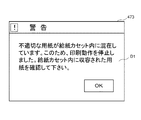
ステップS15の処理で不適切な用紙有りと判定された場合(ステップS16においてYES)、動作制御部100は、画像形成ジョブを停止する(ステップS20)。そして、報知制御部103は、予め定められた警告報知処理を実行する(ステップS21)。報知制御部103は、警告報知として、例えば図10に示すような予め定められた報知画面D1を表示部473に表示させる。
If it is determined in step S15 that there is inappropriate paper (YES in step S16), the
警告報知処理後、給紙カセット15が再セットされた場合には(ステップS22においてYES)、動作制御部100はステップS20の処理で停止した画像形成ジョブを再開し(ステップS23)、ステップS13の処理に戻る。すなわち、判定部102は、用紙束内の不適切な用紙の有無を再度判定する。
If the
一方、ステップS15の処理で不適切な用紙無しと判定された場合(ステップS16においてNO)、動作制御部100は、ピックアップローラー141および搬送ローラー171を回動させて、用紙束から用紙を一枚給紙させる(ステップS17)。そして、動作制御部100は、画像形成部12に、給紙部14から給紙された用紙に画像を形成させる(ステップS18)。その後、画像形成ジョブが完了していない場合(ステップS19においてNO)、ステップS13の処理に戻る。すなわち、判定部102は、用紙束内の不適切な用紙の有無を再度判定する。このように、画像形成装置1では、複数枚の用紙が給紙対象とされる場合に、用紙を1枚給紙する毎に用紙束内の不適切な用紙の有無を判定している。
On the other hand, when it is determined that there is no inappropriate paper in the process of step S15 (NO in step S16), the
なお、複数枚の用紙が給紙対象とされる場合、センサー制御部101は、センサー駆動部147に、第1センサー145および第2センサー146を第1の経路または第2の経路の端部に移動させた後、第1センサー145および第2センサー146を第1の経路または第2の経路の反対側の端部に戻させずに、その後に用紙を1枚給紙した後に、第1センサー145および第2センサー146を第1の経路または第2の経路の反対側の端部に戻させる。
When a plurality of sheets are to be fed, the
例えば、センサー制御部101は、センサー駆動部147に、第1センサー145をホームポジションである位置Aから位置Cまで移動させた後、すぐにはホームポジションである位置Aまで戻させない。センサー制御部101は、その後に用紙が1枚給紙された際に、センサー駆動部147に、第1センサー145をホームポジションである位置Aまで戻させる。第1センサー145がホームポジションである位置Aまで戻る際に、用紙束の上面の段差の有無を検知することができるため、用紙を1枚給紙する度に第1センサー145をホームポジションに戻す動作を省くことができる。
For example, after the
なお、本発明は上記の実施の形態の構成に限られず種々の変形が可能である。 The present invention is not limited to the configuration of the above embodiment, and various modifications can be made.
<変形例1>
図11は、変形例1にかかる画像形成装置の動作の流れを示すフローチャートである。なお、図9のフローチャートで示した処理と同内容の処理については、その説明を省略または簡略する。
<
FIG. 11 is a flowchart illustrating a flow of operations of the image forming apparatus according to the first modification. The description of the processing having the same contents as the processing shown in the flowchart of FIG. 9 is omitted or simplified.
上記の実施の形態にかかる画像形成装置1では、用紙を1枚給紙する毎に用紙束内の不適切な用紙の有無を判定するのに対して、変形例1にかかる画像形成装置では、画像形成ジョブを開始する前に用紙束内の不適切な用紙の有無を判定する。
In the
すなわち、変形例1にかかる画像形成装置は、画像形成ジョブを受け付けてから(ステップS31においてYES)、給紙動作を開始する前、すなわちピックアップローラー141を降下する処理(ステップS36)の前に、ステップS32〜ステップS35に示される用紙束内の不適切な用紙の有無を判定する処理を行う。 That is, after receiving an image forming job (YES in step S31), the image forming apparatus according to the first modification before starting the paper feeding operation, that is, before the process of lowering the pickup roller 141 (step S36). The process of determining whether or not there is an inappropriate sheet in the sheet bundle shown in steps S32 to S35 is performed.
用紙束の最上面に不適切な用紙が存在している場合でなくとも、用紙束の内部に不適切な用紙、例えば小さいサイズの用紙が混入している場合には、用紙束の最上面には段差が発生する。このため、変形例1にかかる画像形成装置は、上記の実施の形態にかかる画像形成装置1と比較して、不適切な用紙の判定精度が劣るものの、用紙1枚毎に第1センサー145および第2センサー146を移動させなくても済むため、不適切な用紙の判定処理に掛かる処理時間を短縮することができる。
Even if improper paper is present on the top surface of the paper bundle, improper paper such as small size paper is mixed inside the paper bundle. A step occurs. For this reason, the image forming apparatus according to the modified example 1 is inferior to the
<変形例2>
図12(A)および図12(B)は、変形例2にかかる画像形成装置の給紙部の構造を示す断面図である。なお、図4に示す上記の実施形態にかかる画像形成装置1の給紙部14と同内容の構成については、同符号を付して説明を省略する。
<Modification 2>
12A and 12B are cross-sectional views illustrating the structure of the sheet feeding unit of the image forming apparatus according to the second modification. In addition, about the structure of the content same as the
上記の実施の形態では、ピックアップローラー141が昇降可能に構成され、ピックアップローラー141を降下させることで、ピックアップローラー141の周面と給紙カセット15に収容された用紙束の最上面とを当接させる場合について説明した。これに対して、変形例2にかかる画像形成装置では、給紙カセット15の載置面151の一部が昇降可能な昇降板152とされている。そして、押し上げ部材157により昇降板152が押し上げられることにより、給紙カセット15に収容された用紙束P1を上昇させて、用紙束P1の最上面とピックアップローラー141の周面とを当接させている(図12(B)参照)。
In the above embodiment, the
この場合、昇降板152が給紙カセット15の載置面151に対して傾斜角度θだけ押し上げられているため、用紙束P1の最上面の用紙も傾斜角度θだけ傾斜している。従って、変形例2にかかる画像形成装置の判定部は、第1センサー145および第2センサー146から出力される出力信号に加えて、当該昇降板152の傾斜角度θに基づき、用紙束の上面の段差の有無を判定する。具体的には、判定部は、第1センサー145および第2センサー146から出力される出力信号の出力値を、傾斜角度θから算出される補正値で補正し、当該補正後の出力値を用いて用紙束の上面の段差の有無を判定する。
In this case, since the elevating
<他の変形例>
上記の実施の形態では、用紙束の高さを検知する構成として2つの超音波センサーを設ける場合を説明したが、本発明は必ずしもこの場合に限定されない。超音波センサーの移動経路が交差するのであれば、3以上の超音波センサーを設けてもよい。
<Other variations>
In the above embodiment, the case where two ultrasonic sensors are provided as a configuration for detecting the height of the sheet bundle has been described, but the present invention is not necessarily limited to this case. If the moving paths of the ultrasonic sensors intersect, three or more ultrasonic sensors may be provided.
1 画像形成装置
10 制御ユニット
11 装置本体
12 画像形成部
14 給紙部
15 給紙カセット
16 レール部
100 動作制御部
101 センサー制御部
102 判定部
103 報知制御部
141 ピックアップローラー
142 昇降駆動部
143 規制位置検知部
144 用紙高さ検知部
145 第1センサー
146 第2センサー
147 センサー駆動部
DESCRIPTION OF
Claims (10)
前記給紙カセットに収容された用紙束から1枚ずつ用紙を給紙するローラーと、
前記給紙カセットの上方に設置され、超音波を前記用紙束の上面に向けて発振するとともに当該用紙束の上面で反射した超音波を受信して、当該受信した超音波に応じた出力信号を出力する2つの超音波センサーと、
前記2つの超音波センサーのうち、一方の超音波センサーを前記給紙カセットの上方に設けられた第1の経路で移動させ、他方の超音波センサーを前記給紙カセットの上方に設けられた第2の経路で移動させる移動機構と、
前記移動機構が前記2つの超音波センサーを移動させている間に前記2つの超音波センサーから出力される出力信号に基づき、前記用紙束内の不適切な用紙の有無を判定する判定部と、
前記判定部が不適切な用紙有りと判定した場合に、前記ローラーによる給紙動作を停止させる制御を行う動作制御部と、を備え、
前記第1の経路と前記第2の経路は、前記給紙カセットの上方で交差している給紙装置。 A paper cassette;
A roller for feeding sheets one by one from a bundle of sheets stored in the sheet cassette;
Installed above the paper feed cassette, oscillates ultrasonic waves toward the upper surface of the sheet bundle, receives ultrasonic waves reflected from the upper surface of the sheet bundle, and outputs an output signal corresponding to the received ultrasonic waves. Two ultrasonic sensors to output,
Of the two ultrasonic sensors, one ultrasonic sensor is moved along a first path provided above the paper cassette, and the other ultrasonic sensor is provided above the paper cassette. A moving mechanism for moving along two routes;
A determination unit that determines the presence or absence of inappropriate paper in the paper bundle based on output signals output from the two ultrasonic sensors while the moving mechanism moves the two ultrasonic sensors;
An operation control unit that performs control to stop the paper feeding operation by the roller when the determination unit determines that there is inappropriate paper , and
The sheet feeding device, wherein the first path and the second path intersect above the sheet feeding cassette .
前記2つの超音波センサーは、前記レール上を往復移動する、請求項1に記載の給紙装置。 The moving mechanism has a rail portion in which two linear rails intersect above the sheet cassette;
The sheet feeding device according to claim 1, wherein the two ultrasonic sensors reciprocate on the rail.
前記給紙カセットに収容された用紙束から1枚ずつ用紙を給紙するローラーと、 A roller for feeding sheets one by one from a bundle of sheets stored in the sheet cassette;
前記給紙カセットの上方に設置され、超音波を前記用紙束の上面に向けて発振するとともに当該用紙束の上面で反射した超音波を受信して、当該受信した超音波に応じた出力信号を出力する2つの超音波センサーと、 Installed above the paper feed cassette, oscillates ultrasonic waves toward the upper surface of the sheet bundle, receives ultrasonic waves reflected from the upper surface of the sheet bundle, and outputs an output signal corresponding to the received ultrasonic waves. Two ultrasonic sensors to output,
前記2つの超音波センサーのうち、一方の超音波センサーを前記給紙カセットの上方に設けられた第1の経路で移動させ、他方の超音波センサーを前記給紙カセットの上方に設けられた第2の経路で移動させる移動機構と、 Of the two ultrasonic sensors, one ultrasonic sensor is moved along a first path provided above the paper cassette, and the other ultrasonic sensor is provided above the paper cassette. A moving mechanism for moving along two routes;
前記移動機構が前記2つの超音波センサーを移動させている間に前記2つの超音波センサーから出力される出力信号に基づき、前記用紙束内の不適切な用紙の有無を判定する判定部と、 A determination unit that determines the presence or absence of inappropriate paper in the paper bundle based on output signals output from the two ultrasonic sensors while the moving mechanism moves the two ultrasonic sensors;
前記判定部が不適切な用紙有りと判定した場合に、前記ローラーによる給紙動作を停止させる制御を行う動作制御部と、を備え、 An operation control unit that performs control to stop the paper feeding operation by the roller when the determination unit determines that there is inappropriate paper, and
前記移動機構は、2本の直線状のレールが前記給紙カセットの上方で交差したレール部を有し、 The moving mechanism has a rail portion in which two linear rails intersect above the sheet cassette;
前記2つの超音波センサーは、前記レール上を往復移動する給紙装置。 The two ultrasonic sensors are paper feeding devices that reciprocate on the rail.
動させるとともに、前記他方の超音波センサーを前記第2の経路の端部から反対側の端部まで移動させ、
前記判定部は、前記ローラーが用紙を1枚給紙する毎に、前記出力信号に基づき前記用紙束内の不適切な用紙の有無を判定する、請求項1乃至請求項4の何れか1項に記載の給紙装置。 In the case where a plurality of sheets are to be fed, the moving mechanism moves the one ultrasonic sensor on the opposite side from the end of the first path every time the roller feeds one sheet. And moving the other ultrasonic sensor from the end of the second path to the opposite end,
5. The determination unit according to claim 1, wherein each time the roller feeds one sheet, the determination unit determines whether there is an inappropriate sheet in the sheet bundle based on the output signal. The paper feeder described in 1.
前記判定部は、前記出力信号に基づき前記用紙束内の不適切な用紙の有無を判定し、
前記動作制御部は、前記判定部が不適切な用紙無しと判定した場合に、停止させていた前記ローラーによる給紙動作を再開させる、請求項1乃至請求項6の何れか1項に記載の給紙装置。 When the sheet feeding cassette is reset after the operation control unit stops the sheet feeding operation by the roller, the moving mechanism moves the one ultrasonic sensor away from the end of the first path. And moving the other ultrasonic sensor from the end of the second path to the opposite end,
The determination unit determines whether or not there is an inappropriate sheet in the sheet bundle based on the output signal;
7. The operation control unit according to claim 1, wherein when the determination unit determines that there is no inappropriate paper, the operation control unit restarts the paper supply operation by the stopped roller. Paper feeder.
前記給紙装置から給紙された用紙に画像を形成する画像形成部と、を備える画像形成装置。 A paper feeding device according to any one of claims 1 to 8,
An image forming apparatus comprising: an image forming unit that forms an image on a sheet fed from the sheet feeding device.
前記給紙カセットに収容された用紙束から1枚ずつ用紙を給紙するローラーと、 A roller for feeding sheets one by one from a bundle of sheets stored in the sheet cassette;
前記給紙カセットの上方に設置され、超音波を前記用紙束の上面に向けて発振するとともに当該用紙束の上面で反射した超音波を受信して、当該受信した超音波に応じた出力信号を出力する2つの超音波センサーと、 Installed above the paper feed cassette, oscillates ultrasonic waves toward the upper surface of the sheet bundle, receives ultrasonic waves reflected from the upper surface of the sheet bundle, and outputs an output signal corresponding to the received ultrasonic waves. Two ultrasonic sensors to output,
前記2つの超音波センサーのうち、一方の超音波センサーを前記給紙カセットの上方に設けられた第1の経路で移動させ、他方の超音波センサーを前記給紙カセットの上方に設けられた第2の経路で移動させる移動機構と、 Of the two ultrasonic sensors, one ultrasonic sensor is moved along a first path provided above the paper cassette, and the other ultrasonic sensor is provided above the paper cassette. A moving mechanism for moving along two routes;
前記移動機構が前記2つの超音波センサーを移動させている間に前記2つの超音波センサーから出力される出力信号に基づき、前記用紙束内の不適切な用紙の有無を判定する判定部と、 A determination unit that determines the presence or absence of inappropriate paper in the paper bundle based on output signals output from the two ultrasonic sensors while the moving mechanism moves the two ultrasonic sensors;
前記判定部が不適切な用紙有りと判定した場合に、前記ローラーによる給紙動作を停止させる制御を行う動作制御部と、を備え、 An operation control unit that performs control to stop the paper feeding operation by the roller when the determination unit determines that there is inappropriate paper, and
前記判定部は、前記移動機構が前記2つの超音波センサーを移動させている間に前記2つの超音波センサーから出力される出力信号に基づき、前記第1の経路および前記第2の経路の下方に位置する前記用紙束の上面の段差の有無を判定し、段差有りと判定する場合に不適切な用紙有りと判定し、段差無しと判定する場合に不適切な用紙無しと判定する給紙装置。 The determination unit is located below the first path and the second path based on output signals output from the two ultrasonic sensors while the moving mechanism moves the two ultrasonic sensors. A paper feeding device that judges whether or not there is a step on the upper surface of the sheet bundle positioned at the position, determines that there is an inappropriate paper when it is determined that there is a step, and determines that there is no inappropriate paper when it is determined that there is no step .
Priority Applications (1)
| Application Number | Priority Date | Filing Date | Title |
|---|---|---|---|
| JP2015080966A JP6344294B2 (en) | 2015-04-10 | 2015-04-10 | Sheet feeding device and image forming apparatus having sheet feeding device |
Applications Claiming Priority (1)
| Application Number | Priority Date | Filing Date | Title |
|---|---|---|---|
| JP2015080966A JP6344294B2 (en) | 2015-04-10 | 2015-04-10 | Sheet feeding device and image forming apparatus having sheet feeding device |
Publications (3)
| Publication Number | Publication Date |
|---|---|
| JP2016199364A JP2016199364A (en) | 2016-12-01 |
| JP2016199364A5 JP2016199364A5 (en) | 2017-02-23 |
| JP6344294B2 true JP6344294B2 (en) | 2018-06-20 |
Family
ID=57422324
Family Applications (1)
| Application Number | Title | Priority Date | Filing Date |
|---|---|---|---|
| JP2015080966A Expired - Fee Related JP6344294B2 (en) | 2015-04-10 | 2015-04-10 | Sheet feeding device and image forming apparatus having sheet feeding device |
Country Status (1)
| Country | Link |
|---|---|
| JP (1) | JP6344294B2 (en) |
Family Cites Families (4)
| Publication number | Priority date | Publication date | Assignee | Title |
|---|---|---|---|---|
| JPS61249782A (en) * | 1985-04-30 | 1986-11-06 | Usac Electronics Ind Co Ltd | System for detecting paper size of printer |
| JP2001247221A (en) * | 2000-03-07 | 2001-09-11 | Riso Kagaku Corp | Paper sheet size detection device |
| JP2010269924A (en) * | 2009-05-25 | 2010-12-02 | Kyocera Mita Corp | Sheet storage device and image forming apparatus |
| JP5588957B2 (en) * | 2011-11-30 | 2014-09-10 | 京セラドキュメントソリューションズ株式会社 | Image forming apparatus |
-
2015
- 2015-04-10 JP JP2015080966A patent/JP6344294B2/en not_active Expired - Fee Related
Also Published As
| Publication number | Publication date |
|---|---|
| JP2016199364A (en) | 2016-12-01 |
Similar Documents
| Publication | Publication Date | Title |
|---|---|---|
| KR101749568B1 (en) | Paper supply unit and control method thereof and image forming apparatus for the same | |
| US10175625B2 (en) | Sheet conveying apparatus which can detect thickness of sheets | |
| JP4137896B2 (en) | Image forming apparatus | |
| JP5533794B2 (en) | Image forming apparatus | |
| JP5346902B2 (en) | Image forming apparatus and consumables used therefor | |
| US9860405B2 (en) | Printing apparatus, printing apparatus control method, and a storage medium | |
| JP5768915B2 (en) | Image forming apparatus and image forming method | |
| US20150185674A1 (en) | Image forming apparatus and print position adjustment method | |
| US9540205B2 (en) | Sheet sorting apparatus | |
| JP5173924B2 (en) | Image forming apparatus | |
| JP6269455B2 (en) | Image processing apparatus, image processing method, and image processing program | |
| JP6344294B2 (en) | Sheet feeding device and image forming apparatus having sheet feeding device | |
| US9451110B2 (en) | Image forming apparatus and image forming method | |
| JP2016199364A5 (en) | ||
| JP6354638B2 (en) | Image reading apparatus, image forming apparatus, and image reading method | |
| JP5919350B2 (en) | Image reading apparatus and image forming apparatus | |
| JP5322768B2 (en) | Image forming apparatus | |
| JP6547708B2 (en) | Image reading apparatus and image forming apparatus | |
| JP7318306B2 (en) | Operation vibration device, image forming device and program | |
| JP7347181B2 (en) | Image forming device | |
| US10284738B2 (en) | Image processing apparatus | |
| JP5941936B2 (en) | Paper sorting device | |
| JP6311673B2 (en) | Sheet conveying apparatus, image forming apparatus, and sheet passing timing determination method | |
| JP6204433B2 (en) | Image reading apparatus and image forming apparatus | |
| JP5723798B2 (en) | Image reading apparatus and image forming apparatus |
Legal Events
| Date | Code | Title | Description |
|---|---|---|---|
| A521 | Written amendment |
Free format text: JAPANESE INTERMEDIATE CODE: A523 Effective date: 20170117 |
|
| A621 | Written request for application examination |
Free format text: JAPANESE INTERMEDIATE CODE: A621 Effective date: 20170222 |
|
| A977 | Report on retrieval |
Free format text: JAPANESE INTERMEDIATE CODE: A971007 Effective date: 20171215 |
|
| A131 | Notification of reasons for refusal |
Free format text: JAPANESE INTERMEDIATE CODE: A131 Effective date: 20180109 |
|
| A521 | Written amendment |
Free format text: JAPANESE INTERMEDIATE CODE: A523 Effective date: 20180205 |
|
| TRDD | Decision of grant or rejection written | ||
| A01 | Written decision to grant a patent or to grant a registration (utility model) |
Free format text: JAPANESE INTERMEDIATE CODE: A01 Effective date: 20180424 |
|
| A61 | First payment of annual fees (during grant procedure) |
Free format text: JAPANESE INTERMEDIATE CODE: A61 Effective date: 20180507 |
|
| R150 | Certificate of patent or registration of utility model |
Ref document number: 6344294 Country of ref document: JP Free format text: JAPANESE INTERMEDIATE CODE: R150 |
|
| LAPS | Cancellation because of no payment of annual fees |