JP6342544B1 - Floor joint device - Google Patents
Floor joint device Download PDFInfo
- Publication number
- JP6342544B1 JP6342544B1 JP2017081739A JP2017081739A JP6342544B1 JP 6342544 B1 JP6342544 B1 JP 6342544B1 JP 2017081739 A JP2017081739 A JP 2017081739A JP 2017081739 A JP2017081739 A JP 2017081739A JP 6342544 B1 JP6342544 B1 JP 6342544B1
- Authority
- JP
- Japan
- Prior art keywords
- joint
- support
- joint plate
- plate
- housing
- Prior art date
- Legal status (The legal status is an assumption and is not a legal conclusion. Google has not performed a legal analysis and makes no representation as to the accuracy of the status listed.)
- Active
Links
- 230000000694 effects Effects 0.000 description 5
- 238000003780 insertion Methods 0.000 description 3
- 230000037431 insertion Effects 0.000 description 3
- 239000004570 mortar (masonry) Substances 0.000 description 3
- 238000002955 isolation Methods 0.000 description 2
- 239000002184 metal Substances 0.000 description 2
- 239000011449 brick Substances 0.000 description 1
- 230000003628 erosive effect Effects 0.000 description 1
- 238000004519 manufacturing process Methods 0.000 description 1
- 239000004579 marble Substances 0.000 description 1
- NJPPVKZQTLUDBO-UHFFFAOYSA-N novaluron Chemical compound C1=C(Cl)C(OC(F)(F)C(OC(F)(F)F)F)=CC=C1NC(=O)NC(=O)C1=C(F)C=CC=C1F NJPPVKZQTLUDBO-UHFFFAOYSA-N 0.000 description 1
- 239000007787 solid Substances 0.000 description 1
Images


Landscapes
- Building Environments (AREA)
Abstract
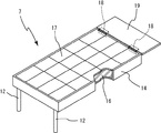
【課題】境界付近に形成された目地部を隙間なく確実に塞ぐことができるとともに、安定して目地プレートを支持でき、低コストで設置できる床用目地装置を提供する。【解決手段】左右の躯体間の目地部2を塞ぐ床用目地装置1であって、躯体の一方の躯体3に設けられた第1の目地プレート支持部と、躯体の他方の躯体4に設けられた第2の目地プレート支持部と、目地部を塞ぐ複数個の目地プレート7と、目地部の下部に左右方向に移動可能に設けられ、目地プレートの底面を支持する複数個の目地プレート支持台8とで構成され、目地プレート支持台は、目地部の下部を左右方向に移動可能に設けられた支持台本体20と、支持台本体を所定の場所に位置させる位置決め機構21と、支持台本体に上下方向に移動可能に設けられ、目地プレートの底面を支持する支持プレート22とから成り、左右の躯体が揺れ動いた場合に、支持プレートは支持台本体と一緒に共働して可動する。【選択図】図1Provided is a floor joint device that can reliably seal a joint portion formed in the vicinity of a boundary without a gap, can stably support a joint plate, and can be installed at low cost. A floor joint device 1 for closing a joint portion 2 between left and right housings, which is provided on a first joint plate support portion provided on one housing 3 of the housing and on the other housing 4 of the housing. A second joint plate support portion, a plurality of joint plates 7 for closing the joint portion, and a plurality of joint plate supports that are provided in the lower part of the joint portion so as to be movable in the left-right direction and support the bottom surface of the joint plate. The joint plate support base is composed of a support base body 20 provided so that the lower part of the joint portion can be moved in the left-right direction, a positioning mechanism 21 for positioning the support base body at a predetermined location, and a support base. The main body includes a support plate 22 that is provided so as to be movable in the vertical direction and supports the bottom surface of the joint plate. When the left and right housings are shaken, the support plate moves together with the support base body. [Selection] Figure 1
Description
本発明は目地部を介して設けられた躯体の間の目地部を塞ぐ床用目地装置に関する。 The present invention relates to a floor joint device for closing joint portions between casings provided via joint portions.
従来、他人の敷地や公道等との境界付近に形成された目地部を塞ぐ床用目地装置としては、「免震ビル等の建物の外壁面と目地部を介して境界線近傍等に設けられ、よう壁の目地部側の上面に形成され、かつ、反目地部側(境界線側)に傾斜面を有する支持凹部と、この支持凹部に一端部が支持され、他端部が前記建物の外壁面寄りの部位に位置する支持目地プレートと、この支持目地プレートの他端部寄りの部位に上部が枢支され、下部が前記よう壁の目地部側の下部位置に枢支された、該支持目地プレートの一端部が前記支持凹部より脱落することなく、かつ支持凹部よりよう壁の上面への移動が可能に支持する支持目地プレート支持体と、前記支持目地プレートにスライド移動可能に支持される一端部が、該支持目地プレートの一端部とほぼ同じ位置に位置し、他端部が前記建物の外壁面に上下移動可能に取付けられた目地プレートとからなることを特徴とする床用目地装置」が知られている(特許文献1)。 Conventionally, as a floor joint device that closes joints formed near the boundaries of other people's sites and public roads, `` installed near the boundary line via the outer wall and joints of seismic isolation buildings, etc. And a support recess formed on the upper surface of the wall joint portion side and having an inclined surface on the anti-joint portion side (boundary line side), one end portion supported by the support recess portion, and the other end portion of the building A support joint plate located near the outer wall surface, and an upper portion pivotally supported at a portion near the other end of the support joint plate, and a lower portion pivotally supported at a lower position on the joint portion side of the wall. One end portion of the support joint plate is supported by the support joint plate so that the end portion of the support joint plate can be moved from the support recess to the upper surface of the wall so as to be slidable from the support recess. One end of the support joint plate Substantially located in the same position, it is known floor joint system "the other end is characterized in that it consists of a vertically movably mounted joint plate on the outer wall surface of the building (Patent Document 1).
しかしながら、このような床用目地装置では、支持目地プレート支持体が枢支金具を支点に回動し、目地プレートや支持目地プレートを支持しているので、枢支金具を深い(低い)位置に設置しなければ、地震による目地プレート等がよう壁側へ移動する際に、支持目地プレート支持体の回転角度が大きくなり、目地プレートの取付端部側の上下方向の移動量が大きくなってしまい、薄板の目地プレートを用いたとしても大きな段差や目地部に隙間を生じるという欠点があった。 However, in such a floor joint device, the support joint plate support rotates around the pivot bracket and supports the joint plate and the support joint plate, so that the pivot bracket is at a deep (low) position. Otherwise, when the joint plate due to an earthquake moves to the wall side, the rotation angle of the support joint plate support increases, and the amount of vertical movement on the attachment plate end side increases. Even if a thin joint plate is used, there is a drawback that a gap is generated in a large step or joint portion.
また、この欠点を解決するために枢支金具を低い位置に設置しようとすると、目地部の下部を相当程度深く掘らなければならず、コストが増大するという欠点があった。 In order to solve this drawback, if the pivotal support metal is installed at a low position, the lower part of the joint portion has to be dug considerably deeply, resulting in an increase in cost.
本発明は以上のような従来の欠点に鑑み、境界付近に形成された目地部を隙間なく確実に塞ぐことができるとともに、安定して目地プレートを支持でき、低コストで設置できる床用目地装置を提供することを目的としている。 In view of the above-described conventional drawbacks, the present invention can reliably seal a joint part formed near the boundary without a gap, can stably support the joint plate, and can be installed at low cost. The purpose is to provide.
本発明の前記ならびにそのほかの目的と新規な特徴は次の説明を添付図面と照らし合わせて読むと、より完全に明らかになるであろう。
ただし、図面はもっぱら解説のためのものであって、本発明の技術的範囲を限定するものではない。
The above and other objects and novel features of the present invention will become more fully apparent when the following description is read in conjunction with the accompanying drawings.
However, the drawings are for explanation only and do not limit the technical scope of the present invention.
上記目的を達成するために、本発明の床用目地装置は、左右の躯体間の目地部を塞ぐ床用目地装置であって、前記躯体の一方の躯体に設けられた第1の目地プレート支持部と、前記躯体の他方の躯体に設けられた第2の目地プレート支持部と、前記第1の目地プレート支持部に一端部側が支持され、前記第2の目地プレート支持部に他端部側が支持され、目地部を塞ぐ複数個の目地プレートと、前記目地部の下部に左右方向に移動可能に設けられ、前記目地プレートの底面を支持する複数個の目地プレート支持台とで構成され、前記目地プレート支持台は、目地部の下部を左右方向に移動可能に設けられた支持台本体と、該支持台本体を所定の場所に位置させる位置決め機構と、前記支持台本体に上下方向に移動可能に設けられ、前記目地プレートの底面を支持する支持プレートとから成り、地震によって左右の躯体が揺れ動いた場合に、前記支持プレートは前記支持台本体と一緒に共働して可動することを特徴とする。 In order to achieve the above object, a floor joint device of the present invention is a floor joint device for closing a joint portion between left and right housings, and supports a first joint plate provided on one housing of the housing. Part, a second joint plate support part provided on the other housing of the housing, and one end side supported by the first joint plate support part, and the other end side of the second joint plate support part Supported by a plurality of joint plates that close the joint portion, and a plurality of joint plate support bases that are provided in the lower portion of the joint portion so as to be movable in the left-right direction, and that support the bottom surface of the joint plate, The joint plate support base is movable in the vertical direction to the support base body, the support base body provided so that the lower part of the joint portion can be moved in the left-right direction, the positioning mechanism for positioning the support base body in a predetermined place, and the support base body Provided in the joint plug Consists of a support plate for supporting the bottom surface of over bets, when the left and right building frame has swings by earthquakes, the support plate is characterized in that movable in cooperation with the pedestal body.
以上の説明から明らかなように、本発明にあっては次に列挙する効果が得られる。
(1)請求項1に記載の発明においては、目地部の下部に左右方向に移動可能に設けられ、目地プレートの底面を支持する複数個の目地プレート支持台を有しているので、第2の目地プレート支持部を長く形成しなくても目地プレートを支持することができ、境界付近に形成された目地部を確実に塞ぐことができる。
(2)また、目地部の下部に左右方向に移動可能に設けられた目地プレート支持台を備えているので、目地部を深く形成する必要がなく、低コストで設置することができる。
(3)請求項2に記載の発明においても、前記(1)〜(2)と同様な効果が得られるとともに、隣り合う目地プレートの接触部分(継ぎ目部分)に目地プレート支持台を配置しているので、地震によって左右の躯体が前後方向に揺れ動いた場合であっても、目地プレートをガタつかせることなく支持することができる。
As is clear from the above description, the present invention has the following effects.
(1) In the first aspect of the invention, since the joint plate has a plurality of joint plate support bases that are provided in the lower part of the joint portion so as to be movable in the left-right direction and support the bottom surface of the joint plate, Even if the joint plate support portion is not formed long, the joint plate can be supported, and the joint portion formed near the boundary can be reliably closed.
(2) Moreover, since the joint plate support base provided in the lower part of the joint part so that a movement in the left-right direction is provided, it is not necessary to form a joint part deeply and it can install at low cost.
(3) In the invention according to
図1乃至図8は本発明の第1の実施形態を示す説明図である。
図9乃至図12は本発明の第2の実施形態を示す説明図である。
図13乃至図15は本発明の第3の実施形態を示す説明図である。
図16乃至図17は本発明の第4の実施形態を示す説明図である。
9 to 12 are explanatory views showing a second embodiment of the present invention.
13 to 15 are explanatory views showing a third embodiment of the present invention.
16 to 17 are explanatory views showing a fourth embodiment of the present invention.
以下、図面に示す本発明を実施するための形態により、本発明を詳細に説明する。
図1乃至図8に示す本発明を実施するための第1の形態において、1は目地部2を介して設けられた一方の躯体3及び他方の躯体4間に設置された床用目地装置である。
なお、左右方向とは図1(平面視)における左右方向であり、前後方向とは図1における上下方向、上下方向とは図2における上下方向をいう。
Hereinafter, the present invention will be described in detail with reference to the embodiments shown in the drawings.
In the first embodiment for carrying out the present invention shown in FIG. 1 to FIG. 8,
The left-right direction is the left-right direction in FIG. 1 (plan view), the front-rear direction is the up-down direction in FIG. 1, and the up-down direction is the up-down direction in FIG.
また、本発明において躯体とは、建物、道路、スラブ、エレベーターシャフト等の目地プレートを設置可能な建造物をいい、出入口とはドアや扉の設けられた出入口だけではなく、人や車両等が通行できる通路も含むものである。 Further, in the present invention, the frame means a building on which joint plates such as buildings, roads, slabs, and elevator shafts can be installed, and the entrance / exit is not only an entrance / exit provided with doors and doors, but also people and vehicles It also includes a passage that can be accessed.
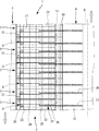
本実施形態の床用目地装置1は、図1乃至図3に示すように、一方の躯体3に設けられた第1の目地プレート支持部5と、他方4の躯体に設けられた第2の目地プレート支持部6と、第1の目地プレート支持部5に一端部が支持され、前記第2の目地プレート支持部6に他端部が支持された複数個の目地プレート7と、複数個の目地プレートの底面を支持する複数個の目地プレート支持台8で構成されている。
As shown in FIG. 1 to FIG. 3, the
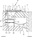
一方の躯体3は、例えば図2に示すように、第1の目地プレート支持部5が形成されるとともに、目地部2の下部に略水平に他方の躯体側へ突出する支持台摺動部9が形成されている。なお、この支持台摺動部9の終端(他方の躯体側の端部)と他方の躯体4との間には下部クリアランス10が形成されている。
For example, as shown in FIG. 2, one
他方の躯体4は、例えば図2に示すように、第2の目地プレート支持部6が形成されるとともに、地震によって目地部2が狭くなった場合に、後述する目地プレート支持台8が入り込む凹所11が形成されている。この凹所11は、境界線Bの近傍まで形成されている。
For example, as shown in FIG. 2, the
第1の目地プレート支持部5は、例えば図2に示すように、本実施形態では一方の躯体3の目地部2側に前後方向に所定間隔を有して複数個設けられた筒状の部材で、この第1の目地プレート支持部5には、後述する目地プレート7の一端部の前後側の両端部に設けられた挿入ピン12が挿入される。
For example, as shown in FIG. 2, the first joint
第2の目地プレート支持部6は、例えば図2に示すように、他方の躯体4の目地部2側の端部に形成された前後方向に延在する凹所状の部位で、目地部2と反対側の端部には、地震によって目地部2が狭くなった場合に、目地プレート7が乗り上げる乗り上げ傾斜面13が形成されている。
For example, as shown in FIG. 2, the second joint
目地プレート7は、図1に示すように、その一端部が第1の目地プレート支持部5に支持されると共に、その他端部が第2の目地プレート支持部6に直接又は間接的に(支持プレートを介して)支持された状態で目地部2の前後方向に複数個隙間なく設けられている。
As shown in FIG. 1, one end of the
この目地プレート7は、図4に示すように、面視長方形状で金属材製の目地プレート本体14と、この目地プレート本体14の一端部の両側部に設けられた前記挿入ピン12と、目地プレート本体14内へ充填されたモルタルあるいはコンクリート16と、このモルタルあるいはコンクリート16の上面に貼り付けられた大理石等のタイルやレンガ等の床化粧板17と、目地プレート本体14の他端部側にヒンジ部材18を介して取り付けられたカバープレート19とで構成されている。
As shown in FIG. 4, the
なお、目地プレート7の一端部側にもヒンジ部材18を介してカバープレート19を備えることにより、隙間や段差が生じることを防止することができる。
In addition, it can prevent that a clearance gap and a level | step difference arise by providing the
目地プレート支持台8は、図1に示すように、複数個の目地プレート7の前後方向の当接部分(隣り合う目地プレート7同士が接触している接触部分)が前後方向の略中央部となるように複数個も受けられている。
As shown in FIG. 1, the
この目地プレート支持台8は、図5に示すように、目地部2の下部に形成された支持台摺動部9を左右方向に移動可能に設けられた支持台本体20と、該支持台本体20を所定の場所に位置させる位置決め機構21と、前記支持台本体20に上下方向に移動可能に設けられ、前記目地プレート7の底面を支持する支持プレート22とで構成されている。
As shown in FIG. 5, the joint
支持台本体20は、下方に4脚の脚部20aが突出すると共に上面がフレーム状に形成されており、その脚部20aにはそれぞれフリーボールベアリング20bが設けられている。支持台本体20は、このフリーボールベアリング20bを介して支持台摺動部9に支持されている。
The
支持台本体20の一方の躯体側の上面には、支持プレート22を上下方向に移動可能に取付ける支持プレート取付具23が設けられている。この支持プレート取付具23は、本実施形態では、前後方向の端部付近に設けられた上方に突出するパイプ状の部材であり、このパイプに支持プレート22の取付ピン24がそれぞれ挿入され、上下方向に移動可能に支持される。
A support
位置決め機構21は、図2に示すように、一方の躯体3の壁面に他方の躯体4側へ突出するように固定され、前記支持台本体20の脚部20aの間に挿入され、脚部20aと当接するバー部材25と、他方の躯体4の壁面にその一端部が固定され、その他端部が支持台本体20に固定されたワイヤー26と、通常状態において目地プレート支持台8が所定の位置に位置するように付勢する付勢具27とで構成されている。この付勢具27は、本実施形態においてはコイルスプリングを用いており、目地部2が狭くなり通常状態に復帰する場合に、目地プレート支持台8を一方の躯体3の方向へ押圧する付勢力が生じ、所定の位置に位置させる。
As shown in FIG. 2, the
なお、本実施形態において、このワイヤー26の長さは、通常状態において目地プレート支持台8が所定の位置に位置している場合の他方の躯体4の壁面から支持台本体20までの長さに設定されている。
In the present embodiment, the length of the
この本実施形態においては1つの目地プレート支持台8に対して脚部20aの内側に当接する2本のバー部材25を備え、このバー部材25によって支持台本体20は一方の躯体3に対して前後方向への移動が制限される。
In this embodiment, two
この所定の位置とは、左右方向については、本実施形態においては通常状態及び目地部が狭くなった状態においては、一方の躯体3の壁面に目地プレート支持台8(支持台本体20)の一方の躯体側の端部が略当接する位置であり、目地部2が広くなった場合には、目地プレート7の他端部側の先端部付近を支持プレートが支持できる位置(他方の躯体4との位置関係が通常状態と同様となる位置)をいう。このような位置に位置決め機構で目地プレート支持台8を位置させることにより、目地プレート7の両端部を常時支持できる。
In the present embodiment, the predetermined position is one of the joint plate support base 8 (support base body 20) on the wall surface of one
支持プレート22は、平面視長方形状の板状の部材であり、その一端部には下方へ突出する取付ピン24が設けられており、この取付ピン24は前記支持プレート取付具23に挿入状態で支持されている。一方その他端部は、第2の目地プレート支持部6に支持されている。
The
隣り合う目地プレート支持台8の支持プレート22同士は、その前後方向の側面が当接するように構成されている。すなわち前後方向に隙間なく支持プレート22が配置されている。
The
目地プレート支持台8(支持台本体20)は、位置決め機構21により所定の位置に位置するので、支持プレート22の他端部は、常時第2の目地プレート支持部6に支持される状態となり、安定して目地プレート7を支持することができる。
Since the joint plate support base 8 (support base body 20) is positioned at a predetermined position by the
地震で躯体3、4が左右方向に揺れ動き目地部2が狭くなると、図6に示すように、目地プレート7は第2の目地プレート支持部6の乗り上げ傾斜面13を乗り上げ、略垂直に上方にせり上がり、他方の躯体4の床面上をスライド移動するとともに、目地プレート支持台8の支持プレート22も乗り上げ傾斜面13によって上方へ略垂直に持ち上げられ他方の躯体4の床面上をスライド移動し、地震による揺れ動きを吸収する。
When the
なお、第1の目地プレート支持部5を一方の躯体3に前後方向に延在する凹所状に形成し、この第1の目地プレート支持部5に枢支ピンを複数個固定し、この枢支ピンで目地プレート7の一端部を枢支状態で支持して目地プレート7及び支持プレート22が斜め状態で乗り上げ傾斜面13をせり上がり、揺れ動きを吸収するように構成してもよい。
The first joint
地震による揺れ動きが終了すると、付勢具27の付勢力により目地プレート支持台8は押圧され、所定の位置に復帰すると共に、目地プレート7及び支持プレート22も通常状態に復帰する。
When the shaking motion due to the earthquake is finished, the
地震で躯体3、4が左右方向に揺れ動き目地部2が広くなると、図7に示すように、目地プレート支持台8はワイヤー26によって他方の躯体4側へ引っ張られ、支持台摺動部9上をスライド移動し、所定の位置に位置する。ここで、支持プレート22は前後方向に隙間なく設けられており、目地プレート支持台8が所定の位置に位置するため、支持プレート22の他方の躯体4側の端部は第2の目地プレート支持部6の上に位置することになる。
When the
これにより、目地プレート7の他端部が第2の目地プレート支持部6に支持されていない状態(支持プレート22のみに支持されている状態)になっても、目地部2が開口することなく地震による揺れ動きを吸収することができる。
Thereby, even if the other end portion of the
地震で躯体3、4が異なる前後方向に揺れ動くと、図8に示すように、目地プレート7の他端部が第2の目地プレート支持部6上を前後方向にスライド移動し、その揺れ動きを吸収する。
When the
この時、目地プレート支持台8も位置決め機構21のバー部材25によって一方の躯体3と同調して揺れ動くため、目地プレート7の前後方向の当接部分(目地プレート本体14の底面の角部)に支持プレートの前後方向の端部が位置することがないため、目地プレート7がガタつくことなく地震による揺れ動きを吸収することができる。なお、ワイヤー26はこの前後方向の動きに追従できるように、前後方向に移動可能で、かつ、地震による揺れ動きが収まった際には、原点位置に復帰できるように取付けるとよい。
At this time, the
[発明を実施するための異なる形態]
次に、図9乃至図17に示す本発明を実施するための異なる形態につき説明する。なお、これらの本発明を実施するための異なる形態の説明に当って、前記本発明を実施するための第1の形態と同一構成部分には同一符号を付して重複する説明を省略する。
[Different forms for carrying out the invention]
Next, different modes for carrying out the present invention shown in FIGS. 9 to 17 will be described. In the description of the different embodiments for carrying out the present invention, the same components as those in the first embodiment for carrying out the present invention are denoted by the same reference numerals, and redundant description is omitted.
図9乃至図12に示す本発明を実施するための第2の形態において、前記本発明を実施するための第1の形態と主に異なる点は、支持台本体20の他方の躯体4側の脚部を平板状の脚部20cに形成し、一方の躯体3にその一端部が取り付けられ、その他端部が支持台本体20の脚部20cに取り付けられたパンタグラフ状の付勢具27Aと、その一端部が他方の躯体4に固定され、その他端部が脚部20cに固定されたワイヤー26とで構成した位置決め機構21Aを備えた目地プレート支持台8Aを用いた床用目地装置1Aにしても、前記本発明を実施するための第1の形態と同様の作用効果を得ることができる。
The second embodiment for carrying out the present invention shown in FIGS. 9 to 12 is mainly different from the first embodiment for carrying out the present invention in that the
図13乃至図15に示す本発明を実施するための第3の形態において、前記本発明を実施するための第1の形態と主に異なる点は、他方の躯体4にバー部材25を設け、他方の躯体4と同調して揺れ動く床用目地装置1Bにしても、前記本発明を実施するための第1の形態と同様の作用効果を得ることができる。
The third embodiment for carrying out the present invention shown in FIGS. 13 to 15 is mainly different from the first embodiment for carrying out the present invention in that a
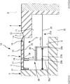
図16及び17に示す本発明を実施するための第4の形態において、前記本発明を実施するための第1の形態と主に異なる点は、一端部が他方の躯体4に固定され、他端部が開口するとともに一方の躯体側に突出する筒部材28と、該筒部材28に一端部側が左右方向にスライド移動可能に挿入され、他端部が支持台本体20に取り付けられた押圧部材29と、前記筒部材28の内部に設けられ、前記押圧部材29を一方の躯体側へ付勢する付勢具27とで構成される位置決め機構21Bを用いた点で、このような床用目地装置1Aにしても前記本発明を実施するための第1の形態と同様の作用効果を得ることができる。
The fourth embodiment for carrying out the present invention shown in FIGS. 16 and 17 is mainly different from the first embodiment for carrying out the present invention in that one end is fixed to the
本実施形態においては筒部材28及び押圧部材29はいずれも角パイプ状の物を用いているが、円筒形状であってもよいし、押圧部材については中実の部材を用いてもよい。
この位置決め機構21Bには、前記押圧部材29が筒部材28から脱落しないように脱落防止用ストッパー(図示せず)を用いることが望ましい。
In the present embodiment, the
It is desirable to use a stopper (not shown) for preventing the pressing
なお、本発明の実施形態においては、支持台摺動部を有する目地部に用いる形態について説明したが、前記特許文献1のような免震建築物に用いてもよい。
また、第1の目地プレート支持部は一方の躯体を加工することによって形成したが、一方の躯体の壁面に目地プレート取付金具等を固定し、この金具を第1の目地プレート支持部としてもよい。
In addition, in embodiment of this invention, although the form used for the joint part which has a support stand sliding part was demonstrated, you may use for the seismic isolation building like the said
In addition, the first joint plate support portion is formed by processing one housing, but a joint plate mounting bracket or the like may be fixed to the wall surface of the one housing, and this bracket may be used as the first joint plate support portion. .
さらに、本発明の実施形態においては、浅皿状の目地プレートを使用しているが、薄板の目地プレートを用いた場合には、地震発生時に目地プレート等が他方の躯体に乗り上げた場合でも、目地プレートにより生じる段差を最低限にすることができる。 Furthermore, in the embodiment of the present invention, a shallow plate-shaped joint plate is used, but when a thin plate joint plate is used, even when the joint plate or the like rides on the other housing at the time of the earthquake, The level difference caused by the joint plate can be minimized.
本発明は床用目地装置を製造する産業で利用される。 The present invention is used in the industry for manufacturing floor joint devices.
1、1A、1B、1C:床用目地装置、2:目地部、
3:一方の躯体、 4:他方の躯体、
5:第1の目地プレート支持部、 6:第2の目地プレート支持部、
7:目地プレート、 8、8A:目地プレート支持台、
9:支持台摺動部、 10:下部クリアランス、
11:凹所、 12:挿入ピン、
13:乗り上げ傾斜面、 14:目地プレート本体、
16:モルタルあるいはコンクリート、
17:床化粧板、 18:ヒンジ部材、
19:カバープレート、 20:支持台本体、
21、21A、21B:位置決め機構、22:支持プレート、
23:支持プレート取付具、 24:取付ピン、
25:バー部材、 26:ワイヤー、
27、27A:付勢具、 28:筒部材、
29:押圧部材。
1, 1A, 1B, 1C: floor joint device, 2: joint portion,
3: one housing, 4: the other housing,
5: 1st joint plate support part, 6: 2nd joint plate support part,
7: joint plate, 8, 8A: joint plate support,
9: Support base sliding part, 10: Lower clearance,
11: recess, 12: insertion pin,
13: Riding slope, 14: Joint plate body,
16: Mortar or concrete,
17: Floor decorative board, 18: Hinge member,
19: Cover plate, 20: Support base body,
21, 21A, 21B: positioning mechanism, 22: support plate,
23: Support plate mounting tool, 24: Mounting pin,
25: Bar member, 26: Wire,
27, 27A: biasing tool, 28: tube member,
29: A pressing member.
Claims (2)
前記目地プレート支持台は、目地部の下部を左右方向に移動可能に設けられた支持台本体と、該支持台本体を所定の場所に位置させる位置決め機構と、前記支持台本体に上下方向に移動可能に設けられ、前記目地プレートの底面を支持する支持プレートとから成り、地震によって左右の躯体が揺れ動いた場合に、前記支持プレートは前記支持台本体と一緒に共働して可動することを特徴とする床用目地装置。 A floor joint device for closing a joint between the left and right housings, the first joint plate support portion provided in one housing of the housing, and the second joint provided in the other housing of the housing A plate support portion, a plurality of joint plates that are supported at one end by the first joint plate support portion, supported at the other end by the second joint plate support portion, and block the joint portion; and the joint portion It is provided at a lower portion of the joint plate so as to be movable in the left-right direction, and includes a plurality of joint plate support bases that support the bottom surface of the joint plate,
The joint plate support base includes a support base body provided so that the lower part of the joint part can be moved in the left-right direction, a positioning mechanism for positioning the support base body in a predetermined position, and the support base body vertically moved to the support base body. And a support plate that supports the bottom surface of the joint plate, and when the left and right housings are shaken by an earthquake, the support plate moves together with the support base body. Floor joint equipment.
Priority Applications (1)
| Application Number | Priority Date | Filing Date | Title |
|---|---|---|---|
| JP2017081739A JP6342544B1 (en) | 2017-04-18 | 2017-04-18 | Floor joint device |
Applications Claiming Priority (1)
| Application Number | Priority Date | Filing Date | Title |
|---|---|---|---|
| JP2017081739A JP6342544B1 (en) | 2017-04-18 | 2017-04-18 | Floor joint device |
Publications (2)
| Publication Number | Publication Date |
|---|---|
| JP6342544B1 true JP6342544B1 (en) | 2018-06-13 |
| JP2018178596A JP2018178596A (en) | 2018-11-15 |
Family
ID=62555248
Family Applications (1)
| Application Number | Title | Priority Date | Filing Date |
|---|---|---|---|
| JP2017081739A Active JP6342544B1 (en) | 2017-04-18 | 2017-04-18 | Floor joint device |
Country Status (1)
| Country | Link |
|---|---|
| JP (1) | JP6342544B1 (en) |
Families Citing this family (2)
| Publication number | Priority date | Publication date | Assignee | Title |
|---|---|---|---|---|
| JP7433672B1 (en) | 2022-11-28 | 2024-02-20 | ドーエイ外装有限会社 | joint cover device |
| JP7432267B1 (en) | 2023-01-12 | 2024-02-16 | ドーエイ外装有限会社 | floor joint device |
Citations (2)
| Publication number | Priority date | Publication date | Assignee | Title |
|---|---|---|---|---|
| JP3719643B2 (en) * | 2000-06-05 | 2005-11-24 | ドーエイ外装有限会社 | Joint cover device |
| JP3166609U (en) * | 2010-12-28 | 2011-03-10 | 安藤建設株式会社 | Open joint device |
-
2017
- 2017-04-18 JP JP2017081739A patent/JP6342544B1/en active Active
Patent Citations (2)
| Publication number | Priority date | Publication date | Assignee | Title |
|---|---|---|---|---|
| JP3719643B2 (en) * | 2000-06-05 | 2005-11-24 | ドーエイ外装有限会社 | Joint cover device |
| JP3166609U (en) * | 2010-12-28 | 2011-03-10 | 安藤建設株式会社 | Open joint device |
Also Published As
| Publication number | Publication date |
|---|---|
| JP2018178596A (en) | 2018-11-15 |
Similar Documents
| Publication | Publication Date | Title |
|---|---|---|
| JP6342544B1 (en) | Floor joint device | |
| JP6359727B1 (en) | Floor joint device | |
| JP6417449B1 (en) | Floor joint device | |
| JP2018016962A (en) | Joint device for floor | |
| JP5184495B2 (en) | Floor joint device | |
| JP5959013B2 (en) | Floor joint device | |
| JP6239059B1 (en) | Floor joint device | |
| JP6271663B1 (en) | Joint device | |
| JP6417450B1 (en) | Ceiling joint device | |
| JP2011084872A (en) | Joint device for floor | |
| JP6239069B1 (en) | Central maintenance member for joint devices | |
| JP2009249820A (en) | Joint device for boundary | |
| JP2011017185A (en) | Joint device for floor | |
| JP6293202B2 (en) | Joint device | |
| JP2016142114A (en) | Joint apparatus for gradient road surface | |
| JP6309068B1 (en) | Floor joint device | |
| JP6417435B2 (en) | Floor joint device and joint plate | |
| JP6005814B1 (en) | Floor joint device | |
| JP6272423B1 (en) | Floor joint device | |
| JP5184485B2 (en) | Ceiling joint device | |
| JP7252669B1 (en) | Floor joint device | |
| JP5862963B2 (en) | Ceiling joint cover device | |
| JP5727440B2 (en) | Floor joint device | |
| JP5385207B2 (en) | Floor joint device | |
| JP5102264B2 (en) | Floor joint device |
Legal Events
| Date | Code | Title | Description |
|---|---|---|---|
| TRDD | Decision of grant or rejection written | ||
| A01 | Written decision to grant a patent or to grant a registration (utility model) |
Free format text: JAPANESE INTERMEDIATE CODE: A01 Effective date: 20180507 |
|
| A61 | First payment of annual fees (during grant procedure) |
Free format text: JAPANESE INTERMEDIATE CODE: A61 Effective date: 20180516 |
|
| R150 | Certificate of patent or registration of utility model |
Ref document number: 6342544 Country of ref document: JP Free format text: JAPANESE INTERMEDIATE CODE: R150 |
|
| R250 | Receipt of annual fees |
Free format text: JAPANESE INTERMEDIATE CODE: R250 |
|
| R250 | Receipt of annual fees |
Free format text: JAPANESE INTERMEDIATE CODE: R250 |