JP2016142114A - Joint apparatus for gradient road surface - Google Patents
Joint apparatus for gradient road surface Download PDFInfo
- Publication number
- JP2016142114A JP2016142114A JP2015021116A JP2015021116A JP2016142114A JP 2016142114 A JP2016142114 A JP 2016142114A JP 2015021116 A JP2015021116 A JP 2015021116A JP 2015021116 A JP2015021116 A JP 2015021116A JP 2016142114 A JP2016142114 A JP 2016142114A
- Authority
- JP
- Japan
- Prior art keywords
- joint
- plate
- road surface
- joint plate
- support plate
- Prior art date
- Legal status (The legal status is an assumption and is not a legal conclusion. Google has not performed a legal analysis and makes no representation as to the accuracy of the status listed.)
- Granted
Links
Images


Abstract
Description
本発明は境界や壁面近傍の勾配を有する路面に目地部を介して設けられた左右の床躯体に設けられる勾配路面用目地装置に関する。 The present invention relates to a gradient road surface joint device provided on left and right floor frames provided on a road surface having a gradient near a boundary or a wall surface via joint portions.
従来、勾配路面に形成された目地部には、一方の目地部端部の床躯体に目地プレート支持凹部を形成するとともに、他方の目地部端部の床躯体に反目地部側が傾斜面に形成された目地プレートスライド支持凹部を形成し、後端部を前記目地プレート支持凹部にピンで先端部が上下方向へ回動可能に枢支し、先端部を前記目地プレートスライド支持凹部に底面又は支持台をスライド可能に支持して目地部を塞ぐ勾配路面用目地装置が使用されていた。 Conventionally, the joint plate formed on the slope road surface has a joint plate support recess in the floor frame at the end of one joint, and the opposite side of the floor frame at the end of the other joint is formed as an inclined surface. The joint plate slide support recess is formed, and the rear end is pivotally supported by the joint plate support recess with a pin so that the tip can be rotated in the vertical direction, and the tip is supported by the bottom of the joint plate slide support recess. A joint device for a gradient road surface that uses a slidable support to block the joint portion has been used.
しかし、目地プレートの先端部付近に障害物や境界が存在する場合、このような勾配路面用目地装置では目地部が狭くなった際に目地プレートの先端部が障害物に激突したり、境界を越えてしまうという欠点があった。 However, when there are obstacles or boundaries near the tip of the joint plate, with such a gradient road joint device, when the joint becomes narrow, the tip of the joint plate collides with the obstacle, There was a drawback of overcoming.
本発明は以上のような従来の欠点に鑑み、目地プレートの先端部付近に障害物や境界が存在する場合でも、目地部が狭くなった際に目地プレートの先端部が障害物に衝突したり、境界を越えることなく地震による揺れ動きを吸収することができる勾配路面用目地装置を提供することを目的としている。 In view of the above-described conventional drawbacks, the present invention is such that even when an obstacle or boundary exists near the tip of the joint plate, the tip of the joint plate collides with the obstacle when the joint becomes narrow. An object of the present invention is to provide a joint device for a gradient road surface capable of absorbing the shaking motion caused by an earthquake without crossing the boundary.
本発明の前記ならびにそのほかの目的と新規な特徴は次の説明を添付図面と照らし合わせて読むと、より完全に明らかになるであろう。
ただし、図面はもっぱら解説のためのものであって、本発明の技術的範囲を限定するものではない。
The above and other objects and novel features of the present invention will become more fully apparent when the following description is read in conjunction with the accompanying drawings.
However, the drawings are for explanation only and do not limit the technical scope of the present invention.
上記目的を達成するために、本発明は目地部を介して設けられた勾配を有する左右の路面の一方の路面に形成されたスライド支持凹部と、該スライド支持凹部にスライド可能に設けられた支承プレートと、前記スライド支持凹部の反目地部側に後端部が取り付けられ、前記支承プレートに先端部が支持された一方の目地プレートと、前記左右の路面の他方の路面に後端部が支持され、先端部が前記支承プレートに支持された他方の目地プレートとで構成され、地震によって目地部が狭まる方向に揺れ動いた時に、前記一方の目地プレートおよび他方の目地プレートは、前記路面上の障害物に衝突あるいは境界を越えることなく揺れ動きを吸収できることを特徴とする。 In order to achieve the above object, the present invention provides a slide support recess formed on one of the left and right road surfaces having a slope provided through a joint portion, and a support slidably provided in the slide support recess. A rear end portion is attached to the plate, the side opposite to the joint portion of the slide support recess, the one end plate is supported by the support plate, and the rear end portion is supported by the other road surface of the left and right road surfaces. The other end joint plate is supported by the support plate, and the one joint plate and the other joint plate are obstructed on the road surface when the joint portion is swung in a direction narrowing due to an earthquake. It is characterized by being able to absorb swaying motion without colliding with objects or crossing boundaries.
以上の説明から明らかなように、本発明にあっては次に列挙する効果が得られる。
(1)請求項1の発明においては、目地部を一方の目地プレートおよび他方の目地プレートで塞いでいるので、地震によって建物および通路間の目地部の幅が狭くなる方向に揺れ動いても、境界や障害物に目地プレートが激突することなく確実に左右の路面間の目地部を塞ぐことができる。
(2)地震によって目地部が広がる方向に揺れ動いても、支承プレートによって一方の目地プレートと他方の目地プレートが離間した際に目地部が開口しないように塞ぐことができる。
したがって、人や物が一方の目地プレートと他方の目地プレートの隙間から目地部へ脱落することを防止することができる。
(3)請求項2も前記(1)、(2)と同様な効果が得られる。
(4)請求項3も前記(1)、(2)と同様な効果が得られる。
As is clear from the above description, the present invention has the following effects.
(1) In the invention of
(2) Even if the joint is swung in the direction in which the joint is spread, the joint can be blocked from opening when the joint plate is separated from the joint plate by the support plate.
Therefore, it is possible to prevent a person or an object from dropping out from the gap between one joint plate and the other joint plate to the joint portion.
(3) In
(4)
以下、図面に示す本発明を実施するための形態により、本発明を詳細に説明する。
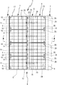
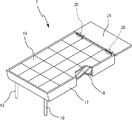
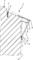
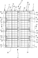
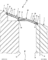
図1ないし図8に示す本発明を実施するための第1の形態において、1は障害物や境界B付近の勾配を有する左右の路面2、3の間の目地部4を塞ぐ勾配路面用目地装置で、この勾配路面用目地装置1は、目地部4を介して設けられた勾配を有する左右の路面2、3の一方の路面2(本実施の形態においては高い方の路面)に形成されたスライド支持凹部5と、該スライド支持凹部5にスライド可能に設けられた支承プレート6と、前記スライド支持凹部5の反目地部側に後端部が取り付けられ、前記支承プレート6に先端部が支持された一方の目地プレート7と、前記左右の路面2、3の他方の路面3(本実施の形態においては低い方の路面)に後端部が支持され、先端部が前記支承プレート6に支持された他方の目地プレート8とで構成されている。
Hereinafter, the present invention will be described in detail with reference to the embodiments shown in the drawings.
In the first embodiment for carrying out the present invention shown in FIG. 1 to FIG. 8,
前記スライド支持凹部5は、一方の路面2に形成されており、スライド支持凹部5の反目地部側の部位には、一方の目地プレート7を支持状態で取り付けるため一方の目地プレート7に固定された枢支ピン9、9が挿入される枢支ピン挿入孔10、10が形成されている。また、一方の目地プレート7の先端部は支承プレート6に支持されるため、左右の路面2、3の表面と一方の目地プレート7の表面が略同一平面上となるように、支承プレート6の厚さ分のスペーサー11を前記枢支ピン挿入孔10、10の間に備えている。
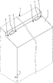
前記支承プレート6は、先端部が前記スライド支持凹部5にスライド可能に支持された支承プレート本体12と、該支承プレート本体12の後端部に回動軸13で軸支状態で先端部が取り付けられ、一方の路面2の外壁2aに取り付けられた取付具14に後端部が取り付けられた複数のアーム15と、該アーム15が一定距離以上一方の路面2の外壁2aから離れないように、アーム15の先端部付近に取り付けられたストッパー16とで構成されている。なお、前記取付具14は、一方の路面2の外壁2aに取り付けられた長孔29を有するガイドレール30と、前記アーム15の後端部に固定され、前記長孔29に回転可能に係合されるアーム回動軸31とで構成されている。
The
The
このように構成することで、支承プレート6は、目地部4が広がる方向に揺れ動き、一方の目地プレート7と他方の目地プレート8が離間した際に、その隙間から目地部4が開口しないように塞ぐことができる。また、本実施の形態においては、ストッパー16としてワイヤーを用いているが、鎖などを用いてもよい。
With this configuration, the
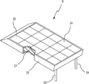
前記一方の目地プレート7は、平面視長方形状で金属材製の一方の目地プレート本体17と、この一方の目地プレート本体17の後端両側部内に設けられ、前記枢支ピン挿入孔10に挿入し一方の目地プレート7を一方の路面2に取り付ける枢支ピン9、9と、一方の目地プレート本体17内へ充填されたモルタルあるいはコンクリート18と、このモルタルあるいはコンクリート18の上面に貼り付けられた大理石等のタイルやレンガ等の床化粧板19と、前記一方の目地プレート本体17の先端部にヒンジ20を介して、先端部が上下方向に回動できるように取付けられたカバープレート21とで構成されている。
前記他方の目地プレート8は、平面視長方形状で、傾斜面22を有する金属材製の他方の目地プレート本体23と、他方の路面3に形成された他方の目地プレート設置凹部24に設けられた枢支ピン挿入孔25と、該枢支ピン挿入孔25に挿入される他方の目地プレート本体23の後端両側部に設けられた他方の目地プレート枢支ピン26、26と、他方の目地プレート本体23内へ充填されたモルタルあるいはコンクリート27と、このモルタルあるいはコンクリート27の上面に貼り付けられた大理石等のタイルやレンガ等の床化粧板28とで構成されている。
The one
The other
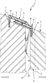
地震で目地部4が狭くなるように左右の路面2、3が揺れ動くと、図7に示すように、一方の目地プレート7は、他方の目地プレート8の後端部側に形成された傾斜面22から他方の目地プレート8上面にせり上がり、その揺れ動きを吸収する。この時支承プレート6は、他方の路面3の外壁に押され、一方の路面2の外壁側へ取付具14のアーム回動軸31を支点にアーム15が回動するとともに、支承プレート本体12がスライド支持凹部5の反目地部側へスライド移動し、境界Bを越えることなく揺れ動きを吸収する。揺れ動きが治まり、左右の路面2、3が元の位置に復帰した際には、自重および他方の目地プレート8の摩擦力により支承プレート6も元の位置に復帰する。この時、支承プレート6が目地部へ脱落しないようにアーム15の一定以上の移動を制限するストッパー16が設けられている。
When the left and
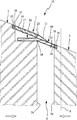
地震で目地部4が広くなるように左右の路面2、3が揺れ動くと、図8に示すように一方の目地プレート7および他方の目地プレート8は、支承プレート6上をスライド移動し、目地部4から脱落することなく、その揺れ動きを吸収する。この時支承プレート6は一方の目地プレート7と他方の目地プレート8に発生した隙間を塞ぎ、この隙間から人や物が目地部へ脱落することを防止する。
When the left and
[発明を実施するための異なる形態]
次に、図9ないし図13に示す本発明を実施するための異なる形態につき説明する。なお、これらの本発明を実施するための異なる形態の説明に当って、前記本発明を実施するための第1の形態と同一構成部分には同一符号を付して重複する説明を省略する。
[Different forms for carrying out the invention]
Next, different modes for carrying out the present invention shown in FIGS. 9 to 13 will be described. In the description of the different embodiments for carrying out the present invention, the same components as those in the first embodiment for carrying out the present invention are denoted by the same reference numerals, and redundant description is omitted.
図9ないし図13に示す本発明を実施するための第2の形態において、前記本発明を実施するための第1の形態と主に異なる点は、他方の目地プレート8Aの先端部に支承プレート6Aを一体に形成し、該一体形成した支承プレート6Aにより他方の目地プレート8Aの先端部を支持している点で、このような構成の床用目地装置1Aにしても前記本発明を実施するための第1の形態と同様な作用効果が得られる。
The second embodiment for carrying out the present invention shown in FIGS. 9 to 13 is mainly different from the first embodiment for carrying out the present invention in that a support plate is provided at the tip of the other
なお、一方の路面2には略水平のスライド支持凹部5Aを形成するとともに、スライド支持凹部5Aの後端部には一方の目地プレート設置凹部32を形成している。前記一方の目地プレート設置凹部32には一方の目地プレート設置ピン33を備えており、一方の目地プレート7Aに形成されたピン収納ボックス34に前記一方の目地プレート設置ピン33が入り込み、一方の目地プレート7Aの後端部がスライド支持凹部5Aの反目地部側に支持された状態になっている。
A substantially horizontal
また、他方の路面3の他方の目地プレート設置凹部24に他方の目地プレート設置ピン35を備えており、他方の目地プレート8Aに形成されたピン収納ボックス36に前記他方の目地プレート設置ピン35が入り込み、他方の目地プレート8Aの後端部が支持される。
Further, the other joint
本実施の形態において、地震で目地部4が狭くなるように左右の路面2、3が揺れ動くと、図12に示すように、一方の目地プレート7Aは、他方の目地プレート8Aの後端部側に一体形成された支承プレート6Aの上面をスライド移動し、その揺れ動きを吸収する。
In the present embodiment, when the left and
地震で目地部4が広くなるように左右の路面2、3が揺れ動くと、図13に示すように、一方の目地プレート7Aは、他方の目地プレート8Aの後端部側に一体形成された支承プレート6Aの上面をスライド移動し、その揺れ動きを吸収する。
When the left and
本発明は勾配路面用目地装置を製造する産業で利用される。 The present invention is used in the industry for manufacturing joint devices for graded road surfaces.
1、1A:勾配路面用目地装置、 2:一方の路面、
3:他方の路面、 4:目地部、
5、5A:スライド支持凹部、 6、6A:支承プレート、
7、7A:一方の目地プレート、 8、8A:他方の目地プレート、
9:枢支ピン、 10:枢支ピン挿入孔、
11:スペーサー、 12:支承プレート本体、
13:回動軸、 14:取付具、
15:アーム、 16:ストッパー、
17:一方の目地プレート本体、 18:モルタルあるいはコンクリート、
19:床化粧板、 20:ヒンジ部材、
21:カバープレート、 22:傾斜面、
23:他方の目地プレート本体、 24:他方の目地プレート設置凹部、
25:枢支ピン挿入孔、 26:他方の目地プレート枢支ピン、
27:モルタルあるいはコンクリート、
28:床化粧板、 29:長孔、
30:ガイドレール、 31:アーム回動軸、
32:一方の目地プレート設置凹部、33:一方の目地プレート設置ピン、
34:ピン収納ボックス、 35:他方の目地プレート設置ピン、
36:ピン収納ボックス、 B:境界。
1, 1A: joint device for slope road surface, 2: one road surface,
3: The other road surface, 4: Joint part,
5, 5A: Slide support recess, 6, 6A: Support plate,
7, 7A: one joint plate, 8, 8A: the other joint plate,
9: pivot pin, 10: pivot pin insertion hole,
11: Spacer, 12: Support plate body,
13: Rotating shaft, 14: Mounting tool,
15: Arm, 16: Stopper,
17: One joint plate body, 18: Mortar or concrete,
19: Floor decorative board, 20: Hinge member,
21: Cover plate, 22: Inclined surface,
23: The other joint plate main body, 24: The other joint plate installation recessed part,
25: pivot pin insertion hole, 26: other joint plate pivot pin,
27: Mortar or concrete,
28: Floor decorative board, 29: Slotted hole,
30: Guide rail, 31: Arm rotation shaft,
32: One joint plate installation recess, 33: One joint plate installation pin,
34: Pin storage box, 35: The other joint plate installation pin,
36: Pin storage box, B: Boundary.
Claims (3)
Priority Applications (1)
| Application Number | Priority Date | Filing Date | Title |
|---|---|---|---|
| JP2015021116A JP6058709B2 (en) | 2015-02-05 | 2015-02-05 | Inclined road joint device |
Applications Claiming Priority (1)
| Application Number | Priority Date | Filing Date | Title |
|---|---|---|---|
| JP2015021116A JP6058709B2 (en) | 2015-02-05 | 2015-02-05 | Inclined road joint device |
Publications (2)
| Publication Number | Publication Date |
|---|---|
| JP2016142114A true JP2016142114A (en) | 2016-08-08 |
| JP6058709B2 JP6058709B2 (en) | 2017-01-11 |
Family
ID=56568378
Family Applications (1)
| Application Number | Title | Priority Date | Filing Date |
|---|---|---|---|
| JP2015021116A Active JP6058709B2 (en) | 2015-02-05 | 2015-02-05 | Inclined road joint device |
Country Status (1)
| Country | Link |
|---|---|
| JP (1) | JP6058709B2 (en) |
Cited By (2)
| Publication number | Priority date | Publication date | Assignee | Title |
|---|---|---|---|---|
| JP7160405B1 (en) * | 2021-10-15 | 2022-10-25 | ドーエイ外装有限会社 | Floor joint device |
| JP7185955B1 (en) | 2021-10-11 | 2022-12-08 | ドーエイ外装有限会社 | Sloping joint plate and floor joint device |
Citations (4)
| Publication number | Priority date | Publication date | Assignee | Title |
|---|---|---|---|---|
| JP2001336222A (en) * | 2000-03-21 | 2001-12-07 | Dooei Gaiso Kk | Floor joint device |
| JP2002348973A (en) * | 2001-05-29 | 2002-12-04 | Dooei Gaiso Kk | Floor joint device |
| JP4499033B2 (en) * | 2005-12-27 | 2010-07-07 | ドーエイ外装有限会社 | Floor joint device |
| JP4907474B2 (en) * | 2007-09-10 | 2012-03-28 | ドーエイ外装有限会社 | Inclined road joint device |
-
2015
- 2015-02-05 JP JP2015021116A patent/JP6058709B2/en active Active
Patent Citations (4)
| Publication number | Priority date | Publication date | Assignee | Title |
|---|---|---|---|---|
| JP2001336222A (en) * | 2000-03-21 | 2001-12-07 | Dooei Gaiso Kk | Floor joint device |
| JP2002348973A (en) * | 2001-05-29 | 2002-12-04 | Dooei Gaiso Kk | Floor joint device |
| JP4499033B2 (en) * | 2005-12-27 | 2010-07-07 | ドーエイ外装有限会社 | Floor joint device |
| JP4907474B2 (en) * | 2007-09-10 | 2012-03-28 | ドーエイ外装有限会社 | Inclined road joint device |
Cited By (3)
| Publication number | Priority date | Publication date | Assignee | Title |
|---|---|---|---|---|
| JP7185955B1 (en) | 2021-10-11 | 2022-12-08 | ドーエイ外装有限会社 | Sloping joint plate and floor joint device |
| JP2023057189A (en) * | 2021-10-11 | 2023-04-21 | ドーエイ外装有限会社 | Ramp joint plate and floor joint device |
| JP7160405B1 (en) * | 2021-10-15 | 2022-10-25 | ドーエイ外装有限会社 | Floor joint device |
Also Published As
| Publication number | Publication date |
|---|---|
| JP6058709B2 (en) | 2017-01-11 |
Similar Documents
| Publication | Publication Date | Title |
|---|---|---|
| JP6058709B2 (en) | Inclined road joint device | |
| JP5706348B2 (en) | Ceiling joint device | |
| JP2018193824A (en) | Floor joint device | |
| JP4499033B2 (en) | Floor joint device | |
| JP5959013B2 (en) | Floor joint device | |
| JP5931476B2 (en) | Boundary joint device | |
| JP6342544B1 (en) | Floor joint device | |
| JP5943862B2 (en) | Floor joint device | |
| JP6271663B1 (en) | Joint device | |
| JP6417450B1 (en) | Ceiling joint device | |
| JP6207537B2 (en) | Ceiling joint device | |
| JP6293202B2 (en) | Joint device | |
| JP6005814B1 (en) | Floor joint device | |
| JP6239069B1 (en) | Central maintenance member for joint devices | |
| JP5862963B2 (en) | Ceiling joint cover device | |
| JP6472484B2 (en) | Central maintenance member for joint devices | |
| JP2016138421A (en) | Floor joint device | |
| JP6243463B2 (en) | Ceiling joint device | |
| JP5203156B2 (en) | Floor joint device | |
| JP5364752B2 (en) | Joint device | |
| JP6204425B2 (en) | Joint device | |
| JP5670966B2 (en) | Joint device | |
| JP6307540B2 (en) | Floor joint device | |
| JP2018131763A (en) | Joint device for floor and joint plate | |
| JP2017203326A (en) | Joint device for ceiling |
Legal Events
| Date | Code | Title | Description |
|---|---|---|---|
| A02 | Decision of refusal |
Free format text: JAPANESE INTERMEDIATE CODE: A02 Effective date: 20160906 |
|
| A521 | Request for written amendment filed |
Free format text: JAPANESE INTERMEDIATE CODE: A523 Effective date: 20161025 |
|
| A911 | Transfer to examiner for re-examination before appeal (zenchi) |
Free format text: JAPANESE INTERMEDIATE CODE: A911 Effective date: 20161101 |
|
| TRDD | Decision of grant or rejection written | ||
| A01 | Written decision to grant a patent or to grant a registration (utility model) |
Free format text: JAPANESE INTERMEDIATE CODE: A01 Effective date: 20161129 |
|
| A61 | First payment of annual fees (during grant procedure) |
Free format text: JAPANESE INTERMEDIATE CODE: A61 Effective date: 20161207 |
|
| R150 | Certificate of patent or registration of utility model |
Ref document number: 6058709 Country of ref document: JP Free format text: JAPANESE INTERMEDIATE CODE: R150 |
|
| R250 | Receipt of annual fees |
Free format text: JAPANESE INTERMEDIATE CODE: R250 |
|
| R250 | Receipt of annual fees |
Free format text: JAPANESE INTERMEDIATE CODE: R250 |