JP6338997B2 - Driving tool - Google Patents
Driving tool Download PDFInfo
- Publication number
- JP6338997B2 JP6338997B2 JP2014214475A JP2014214475A JP6338997B2 JP 6338997 B2 JP6338997 B2 JP 6338997B2 JP 2014214475 A JP2014214475 A JP 2014214475A JP 2014214475 A JP2014214475 A JP 2014214475A JP 6338997 B2 JP6338997 B2 JP 6338997B2
- Authority
- JP
- Japan
- Prior art keywords
- driving
- driving tool
- nose
- inner peripheral
- nose adapter
- Prior art date
- Legal status (The legal status is an assumption and is not a legal conclusion. Google has not performed a legal analysis and makes no representation as to the accuracy of the status listed.)
- Active
Links
Images


Description
この発明は、使用者が手に持って使用する手持ち工具であって、例えば圧縮エア駆動式の釘打ち機等の打ち込み工具に関する。 The present invention relates to a hand-held tool that a user uses in his / her hand, and relates to a driving tool such as a compressed air drive type nailing machine.
釘打ち機等の打ち込み具は、圧縮エアを動力源として往復動する打撃ピストンを内装する本体部と、本体部から打ち込み方向に延びる打ち込みノーズ部と、本体部から側方に延びるハンドル部を備えており、使用者がハンドル部を把持して打ち込みノーズ部の先端(射出口)を打ち込み部位に押し付けて狙いを定めた状態で本体部を起動させることにより、打ち込み具を打ち込み部位に打ち込むことができる。 A driving tool such as a nailing machine includes a main body portion that houses a striking piston that reciprocates using compressed air as a power source, a driving nose portion that extends in the driving direction from the main body portion, and a handle portion that extends laterally from the main body portion. The user can drive the driving tool into the driving site by activating the main body while holding the handle and pressing the tip (injection port) of the driving nose portion against the driving site and aiming. it can.
この種の打ち込み工具では、打ち込み具の長さや太さ(頭部の大きさ)について通常複数種類のものに対応している。一方、打ち込み具が打撃されて下動する打ち込み通路の径(太さ)は固定されている。このため、太い打ち込み具にも対応した打ち込み通路内において細い打ち込み具の先端位置がばらつきやすくなる。特に、短い打ち込み具ほど打ち込み通路内で傾き易く、場合によっては打ち込み具打撃用のドライバの先端に対して打ち込み具の頭部が位置ずれすることにより正しい姿勢で(ドライバの移動方向に対して真っ直ぐに)打撃されず、その結果打ち込み不良の原因になる場合があった。 In this type of driving tool, the length and thickness (size of the head) of the driving tool usually corresponds to a plurality of types. On the other hand, the diameter (thickness) of the driving path in which the driving tool is moved down by being hit is fixed. For this reason, the tip position of the thin driving tool is likely to vary in the driving path corresponding to the thick driving tool. In particular, the shorter the driving tool, the easier it is to tilt in the driving path. In some cases, the head of the driving tool is displaced with respect to the tip of the driver for driving the driving tool. B) There was a case where it was not hit, and as a result, it caused a driving failure.
従来、係る打ち込み不良を防止するために、打ち込み具の打ち込み姿勢を規制するための技術が下記の特許文献に開示されている。下記の特許文献には、主として打ち込み材の傷つき防止を目的として打ち込みノーズ部に装着するノーズアダプタの内周側に円環形状の規制部材を設け、この規制部材により打ち込み具の全周について傾きを規制する技術が開示されている。 Conventionally, in order to prevent such driving defects, techniques for regulating the driving posture of the driving tool are disclosed in the following patent documents. In the following patent document, a ring-shaped restricting member is provided on the inner peripheral side of a nose adapter to be attached to a driving nose portion mainly for the purpose of preventing the driving material from being damaged, and the restricting member is used to tilt the entire circumference of the driving tool. The technology to regulate is disclosed.
しかしながら、上記従来の規制部材は、ドライバガイドに対して上下動可能に設けられたコンタクトアームに装着するノーズアダプタに設けた構成となっていた。コンタクトアームの先端にノーズアダプタを被せるように装着すると、打ち込み部位の視認性が損なわれる問題があった。本発明は、打ち込み部位の視認性を損なうことなく、打ち込み具の打ち込み姿勢を規制部材により規制できるようにすることを目的とする。 However, the conventional restriction member has a configuration provided in a nose adapter attached to a contact arm provided to be movable up and down with respect to the driver guide. When the tip of the contact arm is mounted so as to cover the nose adapter, there is a problem that the visibility of the driving site is impaired. An object of the present invention is to make it possible to regulate the driving posture of a driving tool by a regulating member without impairing the visibility of the driving site.
上記の課題は以下の各発明により解決される。第1の発明は、ドライバガイドの打ち込み通路内に供給された打ち込み具をドライバで打撃して射出口から打ち出す打ち込み工具である。第1の発明では、ドライバガイドに、上下動可能にコンタクトアームを備えている。コンタクトアームは、ドライバガイドを内周側に位置させる円筒形状の円筒部を有している。また、コンタクトアームは、円筒部の打ち込み方向先端側に当該円筒部よりも小径となる材当接部を有している。材当接部の内周孔が打ち込み通路と同径に設定されて射出口とされている。第1の発明では、材当接部の外周側にノーズアダプタを装着可能となっている。ノーズアダプタの内周側に円環形状を有する金属製の規制部材を備えている。この規制部材の内周孔は射出口と同径に設定されている。 Said subject is solved by each following invention. 1st invention is the driving tool which drives the driving tool supplied in the driving path of a driver guide with a driver, and drives out from an injection port. In the first invention, the driver guide is provided with a contact arm that can move up and down. The contact arm has a cylindrical cylindrical portion that positions the driver guide on the inner peripheral side. Further, the contact arm has a material contact portion having a diameter smaller than that of the cylindrical portion on the distal end side in the driving direction of the cylindrical portion. An inner peripheral hole of the material abutting portion is set to have the same diameter as that of the driving passage and serves as an injection port. In the first invention, a nose adapter can be mounted on the outer peripheral side of the material contact portion. A metal regulating member having an annular shape is provided on the inner peripheral side of the nose adapter. The inner peripheral hole of the restricting member is set to have the same diameter as the injection port.
第1の発明によれば、ノーズアダプタの規制部材により打ち込み具の打ち込み姿勢が規制される。規制部材の内周孔と材当接部の内周孔がいずれも打ち込み通路と同径に設定されていることにより、材当接部を打ち込み材に当接させて相対的に上動させた状態では打ち込み通路、当該材当接部の内周孔及びノーズアダプタの内周孔が連続した状態となって打ち込み具が案内されない部位がなくなり、ドライバによる打撃後ノーズアダプタの内周孔から打ち出されるまでの間、打ち込み具の打ち込み姿勢が規制される状態となる。また、ノーズアダプタは小径の材当接部に装着され、円筒部よりも側方へはみ出さない範囲で装着されることから、打ち込み部位(打ち込み具が打ち込み材に打ち込まれる部位)の視認性が確保される。 According to the first invention, the driving posture of the driving tool is regulated by the regulating member of the nose adapter. Since both the inner peripheral hole of the regulating member and the inner peripheral hole of the material contact portion are set to have the same diameter as the driving path, the material contact portion is brought into contact with the driving material and relatively moved upward. In this state, the driving passage, the inner peripheral hole of the material abutting portion, and the inner peripheral hole of the nose adapter are in a continuous state, and there is no portion where the driving tool is not guided, and the driver is driven out from the inner peripheral hole of the nose adapter after being hit by the driver. In the meantime, the driving posture of the driving tool is regulated. In addition, since the nose adapter is attached to the small-diameter material abutting portion and attached in a range that does not protrude laterally from the cylindrical portion, the visibility of the driving site (the site where the driving tool is driven into the driving material) is improved. Secured.
第2の発明は、第1の発明において、ノーズアダプタの外径がコンタクトアームの円筒部の外径に一致している打ち込み工具である。 A second invention is a driving tool according to the first invention, wherein the outer diameter of the nose adapter matches the outer diameter of the cylindrical portion of the contact arm.
第2の発明によれば、ノーズアダプタが円筒部から側方へはみ出さない状態に装着されることにより打ち込み部位の視認性が確保される。 According to the second aspect of the invention, the nose adapter is mounted in a state that does not protrude laterally from the cylindrical portion, thereby ensuring the visibility of the driving site.
第3の発明は、第1又は第2の発明において、ノーズアダプタは打ち込み方向先端側が小径となる円錐形状を有する打ち込み工具である。 According to a third invention, in the first or second invention, the nose adapter is a driving tool having a conical shape having a small diameter on the tip side in the driving direction.
第3の発明によれば、打ち込み部位の視認性を一層高めることができる。 According to the third invention, the visibility of the driving site can be further enhanced.
第4の発明は、第1〜第3の何れか一つの発明において、コンタクトアームの材当接部にノーズアダプタの装着状態を保持する係合部を備えた打ち込み工具である。 A fourth invention is a driving tool according to any one of the first to third inventions, wherein the material abutting portion of the contact arm is provided with an engaging portion that holds the mounting state of the nose adapter.
第4の発明によれば、ノーズアダプタの装着状態を確実に保持することができ、不用意な脱落を防止することができる。 According to the fourth invention, the mounting state of the nose adapter can be reliably held, and inadvertent dropping can be prevented.
第5の発明は、第1〜第4の何れか一つの発明において、ノーズアダプタとして、規制部材の内径について異なる複数種類のノーズアダプタを選択して装着可能な打ち込み工具である。 A fifth invention is a driving tool capable of selecting and mounting a plurality of types of nose adapters different in inner diameter of the regulating member as the nose adapter in any one of the first to fourth inventions.
第5の発明によれば、打ち込む打ち込み具のサイズ(主として頭部の太さ)に合わせてノーズアダプタを交換することにより、打ち込み具の打ち込み姿勢をより確実に規制することができる。 According to the fifth aspect, by replacing the nose adapter in accordance with the size of the driving tool to be driven (mainly the thickness of the head), the driving posture of the driving tool can be more reliably regulated.
第6の発明は、第1〜第5の何れか一つの発明において、ノーズアダプタとして、規制部材の長さについて異なる複数種類のノーズアダプタを選択して装着可能な打ち込み工具である。 A sixth invention is a driving tool according to any one of the first to fifth inventions, wherein a plurality of types of nose adapters having different lengths for the restricting member can be selected and mounted as the nose adapter.
第6の発明によれば、打ち込む打ち込み具のサイズ(主として長さ)に合わせてノーズアダプタを交換することにより、打ち込み具の打ち込み姿勢をより確実に規制することができる。 According to the sixth invention, by replacing the nose adapter in accordance with the size (mainly length) of the driving tool to be driven, the driving posture of the driving tool can be more reliably regulated.
次に、本発明の実施形態を図1〜図4に基づいて説明する。図1に示すように本実施形態に係る打ち込み工具1は、圧縮エアを動力源として上下に往復動する打撃ピストン11を内装した本体部10と、本体部10から打ち込み方向(図1において下方)に延びる打ち込みノーズ部50と、本体部10の側方へ延びるハンドル部30と、多数本の打ち込み具を装填可能なマガジン40を備えている。図1において右側に位置する使用者がハンドル部30を把持して当該打ち込み工具1が用いられる。使用者から見て手前側を当該打ち込み工具1の後ろ側とする。
Next, an embodiment of the present invention will be described with reference to FIGS. As shown in FIG. 1, a driving tool 1 according to the present embodiment includes a
本体部10は、円筒形状の本体ハウジング12を備えている。本体ハウジング12の上部はトップキャップ14で気密に塞がれている。本体ハウジング12内に円筒形のシリンダ13が収容されている。シリンダ13内に上記打撃ピストン11が上下に往復動可能に収容されている。打撃ピストン11はその上室側(ピストン上室)に供給される圧縮エアにより下動して打ち込み具の打撃がなされ、下室側(ピストン下室)に供給される圧縮エアにより上動して初期位置に戻される。図1は、打撃ピストン11が上死点に戻された状態を示している。打撃ピストン11の下面中心に打ち込み具を打撃するためのドライバ15が取り付けられている。ドライバ15は、打ち込み方向に長く延びている。ドライバ15の先端部は、打ち込みノーズ部50の打ち込み通路51内に至っている。打ち込みノーズ部50は、本体部10の下面から下方へ長く延びる概ね円筒形状のドライバガイド52を主体とするもので、その内周側(打ち込み通路51)をドライバ15の先端部が上下に往復動する。
The
シリンダ13の上部外周側にヘッドバルブ16が上下動可能に設けられている。ヘッドバルブ16は圧縮ばね18によって上動方向に付勢されている。ヘッドバルブ16が圧縮ばね18に抗して下動すると、その上端部がトップキャップ14の下面に設けたシール部17から離間して打撃ピストン11の上室が蓄圧室33に対して開かれ、これによりピストン上室に圧縮エアが供給されて打撃ピストン11が下動する。
A
ヘッドバルブ16がエア圧及び圧縮ばね18の付勢力により上動すると、その上端部がシール部17に押圧されてピストン上室が蓄圧室33から気密に遮断される。こうしてヘッドバルブ16が閉じられると、ピストン上室が大気開放通路19を経て大気開放されるとともに、リターンエア室20に貯留された圧縮エアがピストン下室に流入することにより打撃ピストン11が上死点に戻される。このようにヘッドバルブ16の開閉操作によりピストン上室に対して圧縮エアが給排気されて打撃ピストン11が上下に往復動する。
When the
ヘッドバルブ16は、ハンドル部30の基部側下面に設けたトリガバルブ31のオンオフ操作によりなされる。トリガバルブ31のオンオフ操作は、その下方に設けたトリガ32の操作によりなされる。使用者がハンドル部30を把持した手の指先でトリガ32を上方へ引き操作すると、トリガバルブ31がオンしてヘッドバルブ16の下室側(バルブ下室)が大気開放され、その結果上室側(バルブ上室)に作用する圧縮エアによりヘッドバルブ16が圧縮ばね18に抗して下動する。上記したようにヘッドバルブ16が下動すると、ピストン上室に圧縮エアが供給されて打撃ピストン11が下動する。
The
使用者がトリガ32の引き操作を解除すると、トリガバルブ31がオフしてヘッドバルブ16の下室側(バルブ下室)に圧縮エアが供給され、その結果ヘッドバルブ16が上動して閉じられる。上記したようにヘッドバブルが上動すると、打撃ピストン11が上死点に戻される。
When the user releases the pulling operation of the
ハンドル部30の先端には、圧縮エア供給のエアホースを接続するための接続口34が設けられている。ハンドル部30の内部から概ねトップキャップ14の内部に至る範囲が蓄圧室33とされている。接続口34に接続したエアホース(図示省略)を経てエアコンプレッサから蓄圧室33に圧縮エアが供給される。
A
ハンドル部30と打ち込みノーズ部50の間に跨ってマガジン40が装備されている。マガジン40には、2本のワイヤを介して多数本の打ち込み具を一定間隔をおいた並列状態に仮結合してなる連結打ち込み具がコイル状に巻いた状態で装填される。マガジン40から引き出された連結打ち込み具の送り方向端部側が送り機構41に係合されている。送り機構41は送り爪を主体とするもので、この送り爪を連結打ち込み具に係合させた状態で本体部10の打ち込み動作に連動して送り方向に往復動することにより、連結打ち込み具が打ち込み通路51内に向けてピッチ送りされる。連結打ち込み具が送り機構41によりピッチ送りされることにより、打ち込みノーズ部50の打ち込み通路51内に打ち込み具が1本ずつ供給される。
A
打ち込みノーズ部50には、コンタクトアーム60が設けられている。コンタクトアーム60は、打ち込みノーズ部50のドライバガイド52に沿って上下に移動可能に設けられている。コンタクトアーム60の先端には、円筒形状の円筒部61が一体に設けられている。円筒部61の内周側にドライバガイド52が位置している。この円筒部61を打ち込み材Wに当接させた状態で、当該打ち込み工具1を下方に押し下げ操作すると、コンタクトアーム60が相対的に上動する。コンタクトアーム60が上動操作されると、トリガ32の引き操作が有効になってトリガバルブ31がオンする。これに対して、コンタクトアーム60が上動操作されていない状態では、トリガ32の引き操作は無効になってトリガバルブ31はオンせず、従って本体部10の打ち込み動作はなされない。このように、コンタクトアーム60は、トリガ32の不用意な引き操作による打ち込み動作を回避するための安全機構として機能する。
The driving
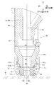
図2には、コンタクトアーム60の円筒部61及びその周辺の詳細が示されている。円筒部61の中心は、ドライバ15の中心軸(打ち込み軸線J0)に一致している。円筒部61は、ドライバガイド52の下方において打ち込み軸線J0と同軸に配置されている。
FIG. 2 shows details of the
円筒部61の下部には、打ち込み方向先端側(下部側)が小径となる円錐形にすぼまった円錐形状部61aが設けられている。円錐形状部61aの下部には、円筒部61(外径D1)よりも細い外径D0の材当接部61bが連続的に設けられている。材当接部61bは、円錐形状部61aの下部から下方へ延びている。このように円筒部61の下部において、円錐形状部61aを経てより細径(細身)の材当接部61bが設けられることにより、打ち込み部位の視認性が確保されている。
At the lower part of the
この材当接部61bの内周側が打ち込み具が打ち出される射出口62とされている。本実施形態では、射出口62はドライバガイド52の内周孔(打ち込み通路51)とほぼ同じ内径d0の円形孔に形成されており、当該打ち込み工具1が打ち込み可能な最長打ち込み具の頭部を通過させるに必要かつ十分な径の射出口に設定されている。これにより射出口62についても、ドライバガイド52の打ち込み通路51と同じく打ち込み具の案内機能を有している。
The inner peripheral side of the
上記したように本実施形態に係る打ち込み工具1は、材当接部61bを直接打ち込み材Wに当接させて本体部10を押し下げ操作することにより打ち込み動作させることができるが、材当接部61bにノーズアダプタ70を装着して用いることもできる。ノーズアダプタ70は、主として打ち込み材Wの傷つき防止、あるいは細径釘の沈み込み防止を目的として装着されるもので、金属製の材当接部61bが打ち込み材Wに直接当接されることを防止してその傷つきを防止するとともに、打ち込み材Wから射出口62を離間させて細径釘等の打ち込み過ぎを防止する機能を有している。
As described above, the driving tool 1 according to the present embodiment can be driven to operate by directly pressing the
このノーズアダプタ70は、円筒形状の本体部71と、本体部71の内周側に取り付けられた規制部材72を備えている。ノーズアダプタ70の本体部71は、適度な弾性を有するウレタンゴムを素材として概ね円筒形状に成形されている。図示するように本体部71の下部は、円錐形状部61aと同様、円錐形にすぼまったスリム形(円錐形状部71b)に形成されている。ノーズアダプタ70の下部が円錐形状をなすスリム形に形成されていることにより、当該ノーズアダプタ70を材当接部61bに装着しても打ち込み部位の良好な視認性が確保されるようになっている。
The
本体部71の内周面上部側には、係合凹部71aが設けられている。係合凹部71aは、打ち込み軸線J0周りの全周にわたって設けられている。これに対して材当接部61bの外周面には、ノーズアダプタ70を装着状態に保持するための係合部61cが設けられている。係合部61cは、打ち込み軸線J0周りの四等分位置に設けられている。本実施形態では、4箇所の係合部61cとして、それぞれ放射方向に張り出す突起部が設けられている。各係合部61cの上面は、打ち込み軸線J0に直交する平坦面に形成されている。本体部71を弾性変形させながら、材当接部61bに被せるように装着すると、係合凹部71aの上部が係合部61cに係合されて当該ノーズアダプタ70が材当接部61bに装着された状態に保持される。
An
ノーズアダプタ70の本体部71の内周側下部には、金属製の規制部材72が設けられている。規制部材72は、円環形状を有し、本体部71の成形時にその内周側下部に固定されている。規制部材72の内周孔72aは、材当接部61bの射出口62と同じ内径d0で形成されている。
A
また、図示するように、材当接部61bにノーズアダプタ70を装着した状態では、材当接部61bの下面が規制部材72の上面にほぼ当接した状態となる。このため、規制部材72の内周孔72aが射出口62に連続して連なった状態に配置される。このため、射出口62と内周孔72aが、打ち込み具の打ち込み姿勢を規制する切れ目のない規制孔として機能するようになっている。
Further, as shown in the figure, when the
以上のように構成した本実施形態の打ち込み工具1によれば、コンタクトアーム60の円筒部61は、打ち込み方向先端側により小径(外径D0)の材当接部61bを有している。また、材当接部61bの内周孔が打ち込み通路51と同じ内径d0に設定されて射出口62とされている。さらに、材当接部61bの外周側にノーズアダプタ70を装着可能となっている。ノーズアダプタ70の内周側に円環形状を有する金属製の規制部材72を備えている。この規制部材72の内周孔72aは射出口62と同じ内径d0に設定されている。
According to the driving tool 1 of the present embodiment configured as described above, the
このことから、ノーズアダプタ70を介して材当接部61bを打ち込み材Wに当接させて相対的に上動させた状態では打ち込み通路52、当該材当接部61bの内周孔(射出口62)及びノーズアダプタ70の内周孔72aが連続した状態となって打ち込み具が案内されない部位がなくなり、ドライバ15による打撃後ノーズアダプタ70の内周孔72aから打ち出されるまで間、打ち込み具の打ち込み姿勢が規制される状態となる。
Therefore, in the state in which the
しかも、本実施形態では、ノーズアダプタ70の外径が円筒部61の外径D1に一致するよう本体部71の外径が設定されている。このため、ノーズアダプタ70が円筒部61よりも側方へはみ出さない状態に装着されており、これにより打ち込み部位(ノーズアダプタ70の打ち込み材Wに対する当接部)の視認性が確保される。また、ノーズアダプタ70の打ち込み方向先端側が円錐形状のスリム形を有していることによっても打ち込み部位の視認性が高められている。
In addition, in the present embodiment, the outer diameter of the
さらに、ノーズアダプタ70は、コンタクトアーム60の材当接部61bに設けた係合部61cを係合凹部71a内に係合させた状態で当該材当接部61bに装着されている。これにより、ノーズアダプタ70の装着状態を確実に保持することができ、ひいては当該ノーズアダプタ70の不用意な脱落を防止することができる。
Further, the
以上説明した実施形態には種々変更を加えることができる。例えば、打ち込み具の長さや太さ等のサイズに合わせてノーズアダプタを交換可能な構成とすることができる。変更を要しない部材及び構成については、同位の符号を用いてその説明を省略する。図3には、第2実施形態に係るノーズアダプタ73が示されている。この第2実施形態に係るノーズアダプタ73は、第1実施形態と同様、ウレタンゴム製の本体部71と、金属製の規制部材74を備えている。規制部材74は円環形状を有し、本体部71の内周側下部に沿って一体化されている。規制部材74の内周孔74aの内径が材当接部61bの内径(射出口62の内径d0)よりも小さくなっている。内周孔74aの上部口元には、曲面形状の案内部74bが設けられている。この案内部74bを経て射出口62から内周孔74a内に打ち込み具がスムースに案内される。このため、第2実施形態に係るノーズアダプタ73によれば、より細い打ち込み具(細径釘)についてその打ち込み姿勢をより確実に規制することができる。
Various modifications can be made to the embodiment described above. For example, it can be set as the structure which can replace | exchange a nose adapter according to sizes, such as the length and thickness of a driving tool. About the member and structure which do not require a change, the description is abbreviate | omitted using a same code | symbol. FIG. 3 shows a
第2実施形態においても、本体部71の内周側上部には係合凹部71aが全周にわたって設けられている。この係合凹部71a内に、材当接部61b側の係合部61cを弾性的に嵌め込んで当該ノーズアダプタ73が当該材当接部61bに装着される。このため、ノーズアダプタ73の材当接部61bからの不用意な脱落が防止される。また、本体部71の下部が円錐形にすぼまったスリム形状(円錐形状部71b)に形成されていることにより、打ち込み部位の視認性が確保されている。
Also in the second embodiment, an engaging
図4には、第3実施形態に係るノーズアダプタ75が示されている。この第3実施形態に係るノーズアダプタ75は、規制部材76の打ち込み軸線J0方向の長さが第1実施形態の規制部材72よりも長くなっている点で第1実施形態とは異なっている。第3実施形態に係る規制部材76の内周孔76aの内径は第1実施形態と同様、射出口62の内径d0に一致している。
FIG. 4 shows a nose adapter 75 according to the third embodiment. The nose adapter 75 according to the third embodiment is different from the first embodiment in that the length of the restricting
規制部材76の内周孔76aが打ち込み軸線J0方向に長く形成されることにより、打ち込み材Wの上面に対する細い打ち込み具(細径釘)の沈み込みをより確実に防止することができる。
By forming the inner
このように、主として内径若しくは長さ等について異なる規制部材72,74,76を備える複数種類のノーズアダプタ70,73,75を、打ち込む打ち込み具のサイズ等に合わせて交換することにより、打ち込み具の打ち込み姿勢をより確実に規制することができる。
As described above, by replacing the plurality of types of
以上例示した実施形態では、ノーズアダプタ70,73,75についてのウレタンゴム製の本体部71を例示したが、硬質樹脂製の本体部としてもよい。
In the embodiment illustrated above, the urethane rubber
1…打ち込み工具
W…打ち込み材
J0…打ち込み軸線
10…本体部
11…打撃ピストン
12…本体ハウジング
13…シリンダ
14…トップキャップ
15…ドライバ
16…ヘッドバルブ
17…シール部
18…圧縮ばね
19…大気開放通路
20…リターンエア室
30…ハンドル部
31…トリガバルブ
32…トリガ
33…蓄圧室
34…接続口
40…マガジン
41…送り機構
50…打ち込みノーズ部
51…打ち込み通路
60…コンタクトアーム
61…円筒部
D0…材当接部の外径、D1…円筒部の外径
61a…円錐形状部、61b…材当接部、61c…係合部
62…射出口、d0…射出口の内径
70…ノーズアダプタ(第1実施形態)
71…本体部、71a…係合凹部
72…規制部材、72a…内周孔
73…ノーズアダプタ(第2実施形態)
74…規制部材、74a…内周孔、74b…案内部
75…ノーズアダプタ(第3実施形態)
76…規制部材、76a…内周孔
DESCRIPTION OF SYMBOLS 1 ... Driving tool W ... Driving material J0 ... Driving
71 ... Main body, 71a ... Engaging
74 ... restricting member, 74a ... inner peripheral hole, 74b ... guide portion 75 ... nose adapter (third embodiment)
76 ... restricting member, 76a ... inner peripheral hole
Claims (7)
前記ドライバガイドに、上下動可能にコンタクトアームを備えており、該コンタクトアームは、前記ドライバガイドを内周側に位置させる円筒形状の円筒部を有し、該円筒部の打ち込み方向先端側に当該円筒部よりも小径となる材当接部を有し、該材当接部の内周孔が前記打ち込み通路と同径に設定されて前記射出口とされ、
該材当接部の外周側にノーズアダプタを装着可能であり、該ノーズアダプタの内周側に円環形状を有する金属製の規制部材を備え、該規制部材の内周孔を前記射出口と同径に設定し、又は前記射出口よりも小径に設定して、
前記コンタクトアームを上動させた状態では、前記材当接部の内周孔と前記規制部材の内周孔により前記打ち込み通路に連続した案内通路が形成される構成とした打ち込み工具。 A driving tool for driving a driving tool supplied in a driving path of a driver guide with a driver and driving it from an injection port,
The driver guide is provided with a contact arm that can move up and down, and the contact arm has a cylindrical cylindrical portion that positions the driver guide on an inner peripheral side, A material abutting portion having a diameter smaller than that of the cylindrical portion, and an inner peripheral hole of the material abutting portion is set to have the same diameter as the driving path, and is the injection port;
A nose adapter can be mounted on the outer peripheral side of the material abutting portion, and a metal restricting member having an annular shape is provided on the inner peripheral side of the nose adapter, and the inner peripheral hole of the restricting member is connected to the injection port. Set to the same diameter, or set to a smaller diameter than the injection port ,
A driving tool configured such that when the contact arm is moved upward, a guide passage that is continuous with the driving path is formed by the inner peripheral hole of the material contact portion and the inner peripheral hole of the restriction member .
The driving tool according to any one of claims 1 to 6, wherein a plurality of types of nose adapters having different lengths of the restriction member can be selected and mounted as the nose adapter.
Priority Applications (1)
| Application Number | Priority Date | Filing Date | Title |
|---|---|---|---|
| JP2014214475A JP6338997B2 (en) | 2014-10-21 | 2014-10-21 | Driving tool |
Applications Claiming Priority (1)
| Application Number | Priority Date | Filing Date | Title |
|---|---|---|---|
| JP2014214475A JP6338997B2 (en) | 2014-10-21 | 2014-10-21 | Driving tool |
Publications (3)
| Publication Number | Publication Date |
|---|---|
| JP2016078200A JP2016078200A (en) | 2016-05-16 |
| JP2016078200A5 JP2016078200A5 (en) | 2017-06-29 |
| JP6338997B2 true JP6338997B2 (en) | 2018-06-06 |
Family
ID=55957209
Family Applications (1)
| Application Number | Title | Priority Date | Filing Date |
|---|---|---|---|
| JP2014214475A Active JP6338997B2 (en) | 2014-10-21 | 2014-10-21 | Driving tool |
Country Status (1)
| Country | Link |
|---|---|
| JP (1) | JP6338997B2 (en) |
Family Cites Families (3)
| Publication number | Priority date | Publication date | Assignee | Title |
|---|---|---|---|---|
| JP3655173B2 (en) * | 2000-06-29 | 2005-06-02 | 株式会社マキタ | Nailer |
| JP4577495B2 (en) * | 2004-11-26 | 2010-11-10 | マックス株式会社 | Driving guide mechanism for screw and nail driving machines |
| JP2011206856A (en) * | 2010-03-29 | 2011-10-20 | Makita Corp | Driving tool |
-
2014
- 2014-10-21 JP JP2014214475A patent/JP6338997B2/en active Active
Also Published As
| Publication number | Publication date |
|---|---|
| JP2016078200A (en) | 2016-05-16 |
Similar Documents
| Publication | Publication Date | Title |
|---|---|---|
| JP6819045B2 (en) | Driving machine | |
| JP5849920B2 (en) | Driving machine | |
| JP5055775B2 (en) | Nailer | |
| JP6338997B2 (en) | Driving tool | |
| JP2016047594A (en) | Driving machine | |
| US10639776B2 (en) | Driving tool | |
| JP6604936B2 (en) | Driving tool | |
| JP2017119330A (en) | Driving machine | |
| JP7073197B2 (en) | Driving tool | |
| JP6102524B2 (en) | Driving tool | |
| JP6369231B2 (en) | Driving machine | |
| JP5538747B2 (en) | Pneumatic tool | |
| JP6776894B2 (en) | On-off valve structure | |
| JP6301217B2 (en) | Driving tool | |
| JP2013193168A (en) | Driving machine | |
| JP6217068B2 (en) | Tool spring structure and tool | |
| JP6604068B2 (en) | Driving tool | |
| TW202120271A (en) | Driving tool | |
| JP6380740B2 (en) | Fastener driving tool | |
| JP2016120573A (en) | Implantation tool | |
| JP2014226734A (en) | Knocking in tool | |
| JP2018118322A (en) | Air pressure tool with air duster | |
| JP2017217747A (en) | Impact tool | |
| JP2011194543A (en) | Driving machine | |
| JP2005059209A (en) | Nailing machine |
Legal Events
| Date | Code | Title | Description |
|---|---|---|---|
| A521 | Request for written amendment filed |
Free format text: JAPANESE INTERMEDIATE CODE: A523 Effective date: 20170517 |
|
| A621 | Written request for application examination |
Free format text: JAPANESE INTERMEDIATE CODE: A621 Effective date: 20170517 |
|
| A131 | Notification of reasons for refusal |
Free format text: JAPANESE INTERMEDIATE CODE: A131 Effective date: 20180227 |
|
| A521 | Request for written amendment filed |
Free format text: JAPANESE INTERMEDIATE CODE: A523 Effective date: 20180411 |
|
| TRDD | Decision of grant or rejection written | ||
| A01 | Written decision to grant a patent or to grant a registration (utility model) |
Free format text: JAPANESE INTERMEDIATE CODE: A01 Effective date: 20180501 |
|
| A61 | First payment of annual fees (during grant procedure) |
Free format text: JAPANESE INTERMEDIATE CODE: A61 Effective date: 20180509 |
|
| R150 | Certificate of patent or registration of utility model |
Ref document number: 6338997 Country of ref document: JP Free format text: JAPANESE INTERMEDIATE CODE: R150 |
|
| R250 | Receipt of annual fees |
Free format text: JAPANESE INTERMEDIATE CODE: R250 |
|
| R250 | Receipt of annual fees |
Free format text: JAPANESE INTERMEDIATE CODE: R250 |
|
| R250 | Receipt of annual fees |
Free format text: JAPANESE INTERMEDIATE CODE: R250 |