JP6338261B1 - Packaging box sheet - Google Patents
Packaging box sheet Download PDFInfo
- Publication number
- JP6338261B1 JP6338261B1 JP2017164042A JP2017164042A JP6338261B1 JP 6338261 B1 JP6338261 B1 JP 6338261B1 JP 2017164042 A JP2017164042 A JP 2017164042A JP 2017164042 A JP2017164042 A JP 2017164042A JP 6338261 B1 JP6338261 B1 JP 6338261B1
- Authority
- JP
- Japan
- Prior art keywords
- side plate
- sheet
- mount
- bottom plate
- release paper
- Prior art date
- Legal status (The legal status is an assumption and is not a legal conclusion. Google has not performed a legal analysis and makes no representation as to the accuracy of the status listed.)
- Active
Links
Images


Classifications
-
- B—PERFORMING OPERATIONS; TRANSPORTING
- B65—CONVEYING; PACKING; STORING; HANDLING THIN OR FILAMENTARY MATERIAL
- B65D—CONTAINERS FOR STORAGE OR TRANSPORT OF ARTICLES OR MATERIALS, e.g. BAGS, BARRELS, BOTTLES, BOXES, CANS, CARTONS, CRATES, DRUMS, JARS, TANKS, HOPPERS, FORWARDING CONTAINERS; ACCESSORIES, CLOSURES, OR FITTINGS THEREFOR; PACKAGING ELEMENTS; PACKAGES
- B65D5/00—Rigid or semi-rigid containers of polygonal cross-section, e.g. boxes, cartons or trays, formed by folding or erecting one or more blanks made of paper
- B65D5/20—Rigid or semi-rigid containers of polygonal cross-section, e.g. boxes, cartons or trays, formed by folding or erecting one or more blanks made of paper by folding-up portions connected to a central panel from all sides to form a container body, e.g. of tray-like form
- B65D5/28—Rigid or semi-rigid containers of polygonal cross-section, e.g. boxes, cartons or trays, formed by folding or erecting one or more blanks made of paper by folding-up portions connected to a central panel from all sides to form a container body, e.g. of tray-like form with extensions of sides permanently secured to adjacent sides, with sides permanently secured together by adhesive strips, or with sides held in place solely by rigidity of material
-
- B—PERFORMING OPERATIONS; TRANSPORTING
- B65—CONVEYING; PACKING; STORING; HANDLING THIN OR FILAMENTARY MATERIAL
- B65D—CONTAINERS FOR STORAGE OR TRANSPORT OF ARTICLES OR MATERIALS, e.g. BAGS, BARRELS, BOTTLES, BOXES, CANS, CARTONS, CRATES, DRUMS, JARS, TANKS, HOPPERS, FORWARDING CONTAINERS; ACCESSORIES, CLOSURES, OR FITTINGS THEREFOR; PACKAGING ELEMENTS; PACKAGES
- B65D5/00—Rigid or semi-rigid containers of polygonal cross-section, e.g. boxes, cartons or trays, formed by folding or erecting one or more blanks made of paper
- B65D5/42—Details of containers or of foldable or erectable container blanks
- B65D5/62—External coverings or coatings
Abstract
【課題】スペースをとらずに運搬や保管することができ、使用時には容易に組み立てて貼り箱を得ることが可能であり美観に優れる包装箱用シートを提供すること。【解決手段】組み立てることによって貼り箱を得るための包装箱用シートであって、シート状の台紙10と、台紙の外側面に配置される化粧紙20を含み、台紙は、多角形の外縁を有する底板11と、底板の外縁における1つの頂点を共有する二辺の各々に接続した第1側板12a及び第2側板12bを有しており、化粧紙は、底板及び/又は第1側板と貼り合わされた第1部位20aと、第2側板に対応付けられた部位であって、第1部位と繋がって第2側板とは貼り合わされずに分離している第2部位20bと、第1部位と繋がって、第1側板の一辺から第2側板側に張り出して設けられた第3部位22を有しており、第2部位及び第3部位の各々は、接着層とこれを被覆する剥離紙30aを有している。【選択図】図1The present invention provides a packaging box sheet that can be transported and stored without taking up space, and can be easily assembled and used in use to obtain a sticky box, and is excellent in aesthetics. A packaging box sheet for obtaining a sticking box by assembling includes a sheet-like mount 10 and a decorative paper 20 disposed on an outer surface of the mount, the mount having a polygonal outer edge. And a first side plate 12a and a second side plate 12b connected to each of two sides sharing one vertex at the outer edge of the bottom plate, and the decorative paper is attached to the bottom plate and / or the first side plate. The first part 20a, the second part 20b that is associated with the second side plate and connected to the first part and separated from the second side plate without being bonded together; It has the 3rd site | part 22 which was connected and protruded from the one side of the 1st side plate to the 2nd side plate side, and each of a 2nd site | part and a 3rd site | part has an adhesive layer and the release paper 30a which covers this have. [Selection] Figure 1
Description
本発明は、貼り箱に組み立て可能な包装箱用シートに関する。 The present invention relates to a packaging box sheet that can be assembled into a box.
菓子、お茶等の商品や贈答品を収納するのに適した包装用箱として、従来から貼り箱が知られている。このような貼り箱を納品する場合、組立された状態の貼り箱を納入先まで運搬することになるので、その重量に比してスペースが多く必要となり、運搬コストが高くなりやすいという不都合がある。また、貼り箱の納品を受けた者もその貼り箱の保管に要するスペースが多く必要となる不都合がある。 A pasting box is conventionally known as a packaging box suitable for storing products such as confectionery and tea, and gifts. When such a box is delivered, since the assembled box is transported to the delivery destination, more space is required than its weight, and there is an inconvenience that the transportation cost tends to be high. . Further, there is a disadvantage that a person who receives the delivery of the sticking box needs a lot of space for storing the sticking box.
上記のような不都合に関して、例えば特開平07−061441号公報(特許文献1)には、一旦組立てられた貼り箱の側板四隅を裁断して貼り箱を偏平化することで、運搬時や保管時の貼り箱の体積を小さくし、使用時には、偏平化した貼り箱の裁断された四隅を接着剤によって接着することで元に戻すという技術が記載されている。 Regarding the inconveniences described above, for example, in Japanese Patent Application Laid-Open No. 07-061441 (Patent Document 1), the four side corners of the once assembled assembly box are cut to flatten the attachment box, so that it can be transported or stored. A technique is described in which the volume of the sticking box is reduced and, when in use, the four corners of the flattened sticking box are restored by bonding with an adhesive.
しかしながら、一旦裁断された貼り箱を再度接着剤によって接着することは、貼り箱を用いる店舗等においてその店員が販売業務の合間に行うには作業の負担が大きい。また、このようにして形成される貼り箱は、接着剤のはみ出し等により裁断前の貼り箱に比べて美観が低下する可能性がある。さらに、貼り箱に収容されるものが菓子等の食品である場合には、箱内側に接着剤が露出して菓子等に触れる可能性もあるので、そのような観点からも改良が望まれる。 However, once the pasted box that has been cut is bonded again with an adhesive, the burden on the work is large for the store clerk to perform between sales operations in a store or the like that uses the pasted box. Further, the sticking box formed in this way may be less aesthetic than the sticking box before cutting due to the protruding of the adhesive. Further, when the food contained in the sticking box is a food such as confectionery, there is a possibility that the adhesive may be exposed inside the box and touch the confectionery.
本発明に係る具体的態様は、スペースをとらずに運搬や保管をすることができ、使用時には容易に組み立てて貼り箱を得ることが可能であり美観にも優れる包装箱用シートを提供することを目的の1つとする。 A specific embodiment according to the present invention provides a packaging box sheet that can be transported and stored without taking up space, and can be easily assembled and used to obtain a sticky box at the time of use. Is one of the purposes.
本発明に係る一態様の包装箱用シートは、組み立てることによって貼り箱を得るための包装箱用シートであって、(a)シート状の台紙と、(b)前記台紙の外側面に配置される化粧紙を含み、(c)前記台紙は、平面視において四角形の外縁を有する底板と、各々が前記底板の外縁における四辺の1つに接続しており、当該底板を挟んで向かい合う2つの第1側板と、各々が前記底板の外縁における四辺の1つに接続しており、当該底板を挟んで向かい合う2つの第2側板と、を有しており、(d)前記化粧紙は、前記底板及び前記第1側板の各々と予め貼り合わされた第1部位と、前記第2側板の各々に対応付けられた部位であって、各々が前記第1部位と繋がっており当該第2側板とは貼り合わされずに分離している2つの第2部位と、各々が前記第1部位と繋がっており、前記2つの第1側板の何れかの一辺から前記第2側板の何れかの側に張り出して設けられた4つの第3部位とを有しており、(e)前記第2部位及び前記第3部位の各々は、接着層と、前記接着層を被覆する剥離紙とを有しており、(f)前記第3部位は、各々、前記剥離紙を剥がしてから、前記接着層を前記第2側板の何れかに接触させて当該第2側板に貼り合わせることによって当該第2側板とこれに隣り合う前記第1側板を連結させるためのものであり、(g)前記化粧紙の前記第2部位は、各々、前記剥離紙を剥がしてから、前記第2側板に貼り合わされた後の前記第3部位を覆って前記第2側板に貼り合わせるためのものである、包装箱用シートである。 The packaging box sheet according to one aspect of the present invention is a packaging box sheet for obtaining a sticking box by assembling, and is arranged on (a) a sheet-like mount and (b) an outer surface of the mount. (C) the mount includes a bottom plate having a quadrangular outer edge in plan view, and each of the two base plates facing each other across the bottom plate , each connected to one of the four sides on the outer edge of the bottom plate . 1 side plate , and each of the second side plates is connected to one of the four sides of the outer edge of the bottom plate and faces each other across the bottom plate, and (d) the decorative paper is the bottom plate and first and site that was previously bonded to each other with each of said first side plate, a portion associated with each of the second side plate, attached to the said each are connected to the first portion second side plate and two second portions are separated without being combined Each has connected with the first portion, has four third portion which is provided to protrude on either side of the second side plate from the two either one side of the first side plate, (E) Each of the second part and the third part has an adhesive layer and a release paper covering the adhesive layer, and (f) each of the third parts has the release paper. after peeling, it is intended for connecting the second side plate and said first side plate adjacent thereto by said adhesive layer is brought into contact with one of the second side plate bonded to the second side plate, (G) Each of the second portions of the decorative paper is for covering the third portion after being peeled off the release paper and then being pasted to the second side plate, and pasting the second portion to the second side plate. It is a sheet for a packaging box.
上記構成によれば、スペースをとらずに運搬や保管をすることができ、使用時には容易に組み立てて貼り箱を得ることが可能であり美観にも優れる包装箱用シートを提供することが可能となる。 According to the above configuration, the packaging box sheet can be transported and stored without taking up space, and can be easily assembled during use to obtain a sticky box, and can be provided with an excellent aesthetic appearance. Become.
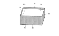
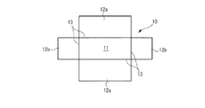
図1は、一実施形態の包装箱用シート1の斜視図であり、包装箱用シート1を台紙10側から見た斜視図を示している。図示の包装箱用シート1は、芯材となる台紙10と、この台紙10の外側面の全体と重なり合うように配置されたシート状の化粧紙20と、を備えている。図2に示すように、包装箱用シート1は、図中の上方に開口部を有する貼り箱に組み立てることが可能である。
FIG. 1 is a perspective view of a
台紙10は、例えば、数mmの厚みを有する板紙で形成されている。台紙10は、平面視において長方形状の外縁を有する底板11と、底板11の外縁の4辺のそれぞれに接続した4つの側板12a、12a、12b、12bを有する。各側板12a等と台紙10の接続する辺には、それぞれ切込溝13が設けられている。これにより、各側板12a等は、底板11に対して屈曲自在に設けられている。
The
各側板12aのうち、例えば図中において底板11よりも上側に配置されている側板12aと、底板11の左側に配置されている側板12bとの関係を見ると、これらは、底板11の外縁における図中左上の1つの頂点を共有する二辺にそれぞれ接続している。別言すれば、これらの側板12aと12bは、底板11の外縁における図中左上の1つの頂点を挟んで隣り合って配置されている。他の側板12aと側板12bとの関係も同様であり、底板11の外縁における何れかの1つの頂点を共有する二辺にそれぞれ1つの側板12aと1つの側板12bが接続されている。
Among the
本実施形態における4つの側板12a、12a、12b、12bは、組み立てた場合に、長方形状の2つの側板12a、12aが互いに向かい合って配置され、かつ、正方形状の2つの側板12b、12bが互いに向かい合って配置される(図2参照)。また、各側板12aは、各々の一面(表面ないし裏面)が互いに同じ面積であり、かつ底板11の一面の面積とも略等しい。また、底板11と各側板12aは、それぞれ、各側板12bの一面(表面ないし裏面)よりも相対的に面積が大きい。各側板12aは、各々の一面(表面ないし裏面)が互いに同じ面積である。
When the four
切込溝13は、底板11と各側板12a、12bのそれぞれが接続する箇所であって、包装箱用シート1を組み立てた後に内側面となる側に直線状に設けられている。各切込溝13は、台紙10を貫通しない溝であり、例えば断面V字型に形成されており、各側板12a、12bの内側への折り曲げを容易にする。なお、各切込溝13は組み立てた際の外側面に設けてもよい。
The
化粧紙20は、包装箱用シート1を貼り箱に組み立てた後の台紙10の外側面全体及び開口部の縁を被覆して装飾するものである(図2参照)。また、化粧紙20は、隣り合う側板12aと12bを連結できるようにする部位を有する。この化粧紙20は、包装箱用シート1を貼り箱に組み立てた場合の外側面に任意の絵柄や模様などを有する。
The
本実施形態では、化粧紙20は、底板11と各側板12aのそれぞれの外側面と対向する第1部位20aが予め位置合わせして貼り合わされている。詳細には、化粧紙20のうち、組み立てた場合に台紙10の底板11と2つの側板12aの外側面を被覆するための第1部位20aが予め底板11と2つの側板12aに位置合わせして貼り付けられている。
In the present embodiment, the
他方で、化粧紙20は、2つの側板12bに対応付けられた第2部位20bについては予め貼り合わされておらず、これらの第2部位20bが各側板12bから分離している。このため、各側板12bは、組み立て前の状態では化粧紙20とは分離独立した状態で切込溝13を軸にして自在に折り曲げることができる(図1参照)。
On the other hand, the
また、図3の部分断面図に示すように、化粧紙20の各側板12bに対応付けられた第2部位20bには、粘着剤層(接着層)30bと、その粘着剤層30bを被覆する剥離紙30aが設けられている。貼り箱を組み立てる際には、各側板12bに対応する第2部位20bに設けられた剥離紙30aを剥がし、この第2部位20bの粘着剤層30bを各側板12bの外側面に接触させることにより、各側板12bに化粧紙20の第2部位20bを容易に貼り合わせることができる。このとき、化粧紙20の各側板12bに対応する第2部位20bは、予め切込溝13の設けられた辺の近傍で化粧紙20の第1部位20aと繋がっており底板11と相対的な位置が合わせられた状態であるので、各側板12bに貼り合わせる際の位置ズレが生じにくい。
Further, as shown in the partial cross-sectional view of FIG. 3, the
化粧紙20の各側板12a、12bに対応する部位のうち、底板11側とは反対側の縁部(すなわち、組み立てた場合の開口部の縁部)には、各側板12a、12bの内側に折り込んで被覆する折込片21が設けられている。これらの折込片21は、各側板12a、12bの縁部とほぼ同じ長さを有し、かつ、折り込むのに必要十分な所定幅(例えば1cm程度)を有している。
Among the portions corresponding to the
各側板12bに対応する折込片21の面のうち、化粧紙20に粘着剤層30bが設けられている面と同じ側の面には、粘着剤層30bとこれを被覆する剥離紙30aが設けられている。本実施形態では化粧紙20の折込片21に設けられる剥離紙30aと第2部位20bに設けられる剥離紙30aが一体化している。貼り箱を組み立てる際には、各折込片21と第2部位20bにわたって設けられた剥離紙30aを剥がし、第2部位20bを側板12bに貼り合わせるとともに折込片21を側板12bの内側に折り込むことで、折込片21を各側板12bの内側に貼り合わせることができる。他方で、各側板12aに対応する折込片21は、予め側板12aの内側に折り込んで貼り合わされている。これらの折込片21により、台紙10の各側板12a、12bの縁部から内側面の一部にわたって化粧紙20で装飾することができるため、各側板12a、12bの縁部の美観を向上させることができる。
Among the surfaces of the
化粧紙20の各側板12aに対応する第1部位20aのうち、底板11側から延びる縁部(側縁部)には、貼り箱を組み立てる際に、隣接する側板12aと側板12bを連結させるための第3部位であるフラップ部22が設けられている。図1に示すように、各フラップ部22は、平面視において化粧紙20の側板12aに対応する第1部位20aと繋がっており、かつ側板12aの一辺から側板12b側に張り出して設けられており、隣り合う一対の側板12a、12bに挟まれる領域に配置されている。
Of the
各フラップ部22は、例えば図示のように台形状の外縁を有しており、その底辺が各側板12aの側縁部とほぼ同じ長さに形成され、この側縁部に対応付けて配置されている。各フラップ部22の面のうち、化粧紙20に粘着剤層30bが設けられている面と同じ側の面には、第2部位20bと同様に、粘着剤層30bとこれを被覆する剥離紙30aが設けられている(図3参照)。貼り箱を組み立てる際には、フラップ部22の剥離紙30aを剥がして、そのフラップ部22を隣接する側板12bの外側面に貼り付けることで、隣り合う一対の側板12aと側板12bを連結することができ、包装箱用シート1を容易に組み立てることができる。このため、各フラップ部22は、側板同士を連結するに必要十分な幅(例えば1cm程度)を有している。
Each
本実施形態の包装箱用シート1は上記のような構成を備えており、次にその組み立ての手順について図4を参照しながら説明する。なお、以下に示す手順は一例であり、組み立てに矛盾を生じない限りにおいて各手順を入れ替えることもできる。
The
まず、図1に示すような平坦な状態から、図4(A)に示すように、切込溝13に沿って各側板12a、12bを略90度折り曲げて底板11に対して直立させる。次に、各フラップ部22の剥離紙30aを剥ぎ、隣り合う側板12a、12bの一辺同士を接した状態にして、各フラップ部22を各側板12bの外側面に貼り合わせる。これにより、隣り合う側板12a、12b同士がそれぞれ連結される。
First, from the flat state as shown in FIG. 1, as shown in FIG. 4A, the
次に、図4(B)に示すように、化粧紙20の各側板12bに対応する第2部位20bと折込片21に対応する剥離紙30aを剥いで、各側板12bの外側面に化粧紙20を貼り合わせるとともに、各折込片21を各側板12bの内側へ折り込んで各側板12bの内側面に貼り合わせる。以上により、貼り箱が完成する(図2参照)。
Next, as shown in FIG. 4B, the
以上のような実施形態の包装箱用シート1によれば、組み立て前はシート状であるので、包装箱用シート1を省スペースかつ低コストで納入先に搬送することができる。また、納入先では、保管スペースが少なくて済み、かつ、貼り箱が必要となった際には、組立者に特別な技量や器用さがなくても、簡単に美観に優れた包装用箱(貼り箱)を組み立てることができる。詳細には、底板11と各側板12aを予め化粧紙20と貼り合わせているので、菓子店などの現場での組み立て時に化粧紙20の位置ズレを生じにくくなる。また、各側板12bと化粧紙20は予め接着されてないため、隣り合う一対の側板12aと側板12bをフラップ部22によって連結させた後に、そのフラップ部22を覆い隠すようにして化粧紙20の部位を側板12bに貼り合わせることで、フラップ部22が外観上見えない状態にすることができる。それにより、貼り箱の美観が向上する。なお、敢えてフラップ部22が外側に現れるようにして組み立てることでも通常にない趣向の外観を得られるので、そのような組み立て方も排除しない。
According to the
次に、上記した実施形態の包装箱用シート1の製造方法の一例について説明する。
Next, an example of the manufacturing method of the
まず、化粧紙20の母材となる化粧紙シート120の上面に粘着剤を塗布する等によって粘着剤層30bを形成し、その上面に、剥離紙30aの母材となる剥離紙シート130aを貼り合わせる(図5参照)。これにより、化粧紙シート120、粘着剤層30b、剥離紙シート130aの順に積層された部材が形成される。
First, the pressure-
次に、化粧紙シート120等の積層された部材の型抜きをする。ここでは、型抜き用のカッターとして2通りの深さのもの用意し、そのうち1つのカッターは積層された部材の裏まで到達する深さとし、他の1つのカッターは裏まで到達せずに剥離紙シート130a側から圧入した場合に剥離紙シート130aのみに到達し、あるいは剥離紙シート130aと粘着剤層30bには到達するが化粧紙シート120には到達しない程度の深さとする。
Next, the laminated members such as the
そして、深さの相対的に深いカッターを剥離紙シート130a側から圧入することにより、図5に示すように、包装箱用シート1の輪郭線、すなわち、台紙10の平面視における外縁形状に折込片21及びフラップ部22の外縁形状を加えた外形の輪郭線24に沿って、剥離紙シート130a、粘着剤層30b及び化粧紙シート120を切断する。
Then, by press-fitting a relatively deep cutter from the
次に、深さの相対的に浅いカッターを剥離紙30a側から圧入することにより、台紙10の底板11、各側板12aおよび各側板12aの折込片21に対応する領域である矩形領域の輪郭線26に沿って、剥離紙シート130aを切断する。
Next, a contour line of a rectangular region which is a region corresponding to the
なお、上記した深さの異なる2つのカッターを同時に圧入して裁断してもよい。 Note that two cutters having different depths described above may be simultaneously press-fitted and cut.
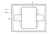
次に、図6に示すように、輪郭線26に対応して入れた切込みに沿って剥離紙30aを剥いで、この領域の粘着剤層30bを露出させる。図6では、粘着剤層30bの露出した領域が分かりやすくなるようにこの領域に模様を付して示している。
Next, as shown in FIG. 6, the
一方で、板紙シートの型抜きをすることにより台紙10を形成する(図7参照)。併せて、切込溝13も形成する。
On the other hand, the
次に、図8に示すように、上記工程で露出させた粘着剤層30bの上に、切込溝13が形成されていない面が粘着剤層30bと対向するようにして台紙10を載置し貼り合わせる。この際に、剥離紙30aを剥いで粘着剤層30bを露出させた領域と、台紙10の底板11及び各側板12aの各外側面が正確に重なり合うように位置合わせして、両者を貼り合わせる。この工程は、製造工場における専用設備を用いる等によって行うことができるので、位置合わせの精度を高くすることができる。その後、各側板12aの折込片21を各側板12aの内側面に貼り合わせることで図1に示す包装箱用シート1が完成する。
Next, as shown in FIG. 8, the
なお、本発明は上述した実施形態の内容に限定されるものではなく、本発明の要旨の範囲内において種々に変形して実施をすることが可能である。例えば、折込片21が省略されてもよい。また、底板11と側板12a、12bの平面視形状(外縁形状)は一例であり、例えば、底板11の平面視における外縁形状は、四角形以外の多角形であってもよい。
In addition, this invention is not limited to the content of embodiment mentioned above, In the range of the summary of this invention, it can change and implement variously. For example, the
また、上記した実施形態では、化粧紙20を底板11及び2つの側板12aの3面に予め貼り合わせているが、これに限定されることはなく、化粧紙20は、台紙10の少なくとも1つの板(底板11または各側板12a、12bの何れか1つ)に予め位置合わせして貼り合わされていればよい。この場合には、台紙の底板や各側板のうちで最も面積の多きものに貼り合わせることがより好ましい。台紙10と化粧紙20の位置決め精度が向上するともに、運搬時などに台紙10と化粧紙20の分離した部分がより少なくなるので包装箱用シート1を取扱いやすくなる。また、化粧紙20と貼り合わせない板については、粘着剤層30bと剥離紙30aを設けておくとよい。
In the above-described embodiment, the
化粧紙20をいずれか1つの板と貼り合わせておく場合には、例えば、底板11と貼り合わせておくことも好ましい。底板11と化粧紙20を予め貼り合わせておくことで、この底板11の4辺において、各側板12a、12bに対応付けられる化粧紙20の各部位が予め位置決めされることになるので、組み立て時に化粧紙20の各部位を各側板12a、12bに貼り合わせる際に化粧紙20の位置ズレを生じにくくなる。なお、化粧紙20を何れか1つの側板12a又は側板12bと予め貼り合わせておいてもよいし、底板11と1つの側板12aの2つと予め貼り合わせておいてもよい。
When the
また、上記した実施形態では、長方形状の底板11に対して4つの側板12a、12bを設けたが、これに限らず、3つの側板12a、12a、12b又は3つの側板12a、12b、12bのみを設け、組み立てた場合に2方向に開口部が形成されるようにしてもよい。あるいは、2つの側板12a、12bのみを設け、組み立てた場合に3方向に開口部が形成されるようにしてもよい。
In the above-described embodiment, the four
また、図9に示すように、化粧紙20について、各側板12bの一辺から側板12a側に張り出すようにして折込片42を設けてもよい。この場合の各折込片42には、粘着剤層30bとこれを被覆する剥離紙30aが設けられる。このような折込片42を設けることで、図10に示すように、1つの側板12aを開閉できるように貼り箱を得ることができる。この場合、各折込片42を各側板12bの内側へ折り込み、かつ各フラップ部22を側板12aの内側へ折り込むようにしてそれぞれ貼り合わせることで、開閉可能な側板12aの内側の美観を高めることができる。
Further, as shown in FIG. 9, the
また、上記した実施形態では、化粧紙20の各側板12bに対応する第2部位20bと折込片21に対応する剥離紙30aと各フラップ部22の剥離紙30aとを別々に設けていたが、これらは連結していてもよい。この場合には、例えば図11に示すように、1つの第2部位20bとこれに対応して両側にそれぞれ設けられている2つのフラップ部22を一体の剥離紙で覆うようにした矩形状の剥離紙230aを設けることも好ましい。この場合、図示の例のように、矩形状の剥離紙230aは、その一辺が各側板12aおよび底板11の端部と揃い、これと対向する一辺が折込片21の端部と揃うようにすることが好ましい。さらに、剥離紙230aは、これを台紙10と合わせた全体の外縁が平面視においてほぼ矩形状となるように設けられるのが好ましい。それにより、多数の包装箱用シート201を重ねたものを搬送用ボックスに収容した際に、包装箱用シート201の位置ズレを生じにくくすることができ、包装箱用シート201の破損を防ぐことができる。また、第2部位20bと各フラップ部22を覆う剥離紙230が連結して一体化しているので、貼り箱の組み立て時には一度の作業で剥離紙230を剥がすことができる。
In the above-described embodiment, the
図12は、上記した図11に示した変形例の包装箱用シートの製造方法の一例について説明するための図である。図12(A)に示すように、母材となる化粧紙シートを型抜きすることにより化粧紙20を形成する。次に、図12(B)に示すように、この形成した化粧紙20の一面全体に粘着剤層30bを設ける。次に、図12(C)に示すように、予め用意しておいた矩形状の剥離紙230aを所定位置(折込片21および第2部位20bを覆う位置)にそれぞれ貼り合わせる。次に、図12(D)に示すように、化粧紙20のうち、剥離紙230aに覆われていない矩形状の部分に位置合わせして台紙10を貼り合わせる。その後、図12(E)に示すように、折込片21を折り込んで台紙10の内面側に貼り合わせる。以上により、変形例の包装箱用シート201が完成する。
FIG. 12 is a diagram for explaining an example of a manufacturing method of the packaging box sheet of the modified example shown in FIG. 11 described above. As shown in FIG. 12A, the
この製造方法では、上記した実施形態の製造方法に比べ、型抜きの必要な工程が化粧紙20を形成する工程のみとなる点や、台紙10の底板11および側板12aに対応する部分に剥離紙を一旦設けてそれを剥ぐという工程が不要となる点などから、製造工程の省力化を実現することができるとともに、剥離紙の使用量も低減することができる。
In this manufacturing method, as compared with the manufacturing method of the above-described embodiment, the release paper is provided on the portion corresponding to the
なお、図12(F)に示すように、剥離紙230aを大きめに作っておき、図中の上下方向においてフラップ部22よりもはみ出すように設けてもよい。この場合、搬送用ボックスに収容した際に、この搬送用ボックスの内面と台紙10の折込片21に覆われた側の端部との間に隙間が生じるので、包装箱用シート201を袋などで包まずに収容した場合であっても台紙10の端部の化粧紙20の破損(擦れなど)を防ぐことができる。
As shown in FIG. 12F, the
1:包装箱用シート
10:台紙
11:底板
12a、12b:側板
13:切込溝
20:化粧紙
20a:第1部位
20b:第2部位
21:折込片
22:フラップ部(第3部位)
24、26:輪郭線
30a:剥離紙
30b:粘着剤層
1: Sheet for packaging box 10: Mount 11:
24, 26:
Claims (5)
シート状の台紙と、
前記台紙の外側面に配置される化粧紙と、
を含み、
前記台紙は、
平面視において四角形の外縁を有する底板と、
各々が前記底板の外縁における四辺の1つに接続しており、当該底板を挟んで向かい合う2つの第1側板と、
各々が前記底板の外縁における四辺の1つに接続しており、当該底板を挟んで向かい合う2つの第2側板と、
を有しており、
前記化粧紙は、
前記底板及び前記第1側板の各々と予め貼り合わされた第1部位と、
前記第2側板の各々に対応付けられた部位であって、各々が前記第1部位と繋がっており当該第2側板とは貼り合わされずに分離している2つの第2部位と、
各々が前記第1部位と繋がっており、前記2つの第1側板の何れかの一辺から前記第2側板の何れかの側に張り出して設けられた4つの第3部位と、
を有しており、
前記第2部位及び前記第3部位の各々は、接着層と、前記接着層を被覆する剥離紙とを有しており、
前記第3部位は、各々、前記剥離紙を剥がしてから、前記接着層を前記第2側板の何れかに接触させて当該第2側板に貼り合わせることによって当該第2側板とこれに隣り合う前記第1側板を連結させるためのものであり、
前記化粧紙の前記第2部位は、各々、前記剥離紙を剥がしてから、前記第2側板に貼り合わされた後の前記第3部位を覆って前記第2側板に貼り合わせるためのものである、
包装箱用シート。 A packaging box sheet for obtaining a box by assembling,
A sheet-like mount,
Decorative paper disposed on the outer surface of the mount,
Including
The mount is
A bottom plate having a rectangular outer edge in plan view;
Each connected to one of the four sides at the outer edge of the bottom plate, two first side plates facing each other across the bottom plate ;
Each connected to one of the four sides at the outer edge of the bottom plate, two second side plates facing each other across the bottom plate ,
Have
The decorative paper is
A first portion pre-bonded to each of the bottom plate and the first side plate;
A portion associated with each of the second side plate, and two second portions, each being separated without bonded to the first portion and connected and said second side plate,
Each has connected with the first portion, and four third portion which is provided to protrude on either side of the second side plate from the two either one side of the first side plate,
Have
Each of the second part and the third part has an adhesive layer and a release paper covering the adhesive layer,
Said third portion are each from peeling the release paper, adjacent thereto and the second side plate by said adhesive layer is brought into contact with one of the second side plate bonded to the second side plate wherein For connecting the first side plates ,
Each of the second portions of the decorative paper is for covering the third portion after being peeled off the release paper and then being pasted to the second side plate, and pasting the second portion to the second side plate.
Packaging box sheet.
請求項1に記載の包装箱用シート。 The release paper of each of the second parts and the release paper of each of the two third parts provided on both sides thereof are connected integral release papers .
The sheet | seat for packaging boxes of Claim 1.
請求項2に記載の包装箱用シート。 The integral release paper is provided such that the entire outer edge combined with the mount is rectangular in plan view.
The sheet | seat for packaging boxes of Claim 2.
請求項1〜3の何れか1項に記載の包装箱用シート。 The third portion has a trapezoidal outer edge having a base having the same length as the side edge of the first side plate.
The sheet | seat for packaging boxes of any one of Claims 1-3.
請求項1〜4の何れか1項に記載の包装箱用シート。
The mount has a cut groove that is V-shaped in cross section and does not penetrate the mount at a connection location between the bottom plate and the first side plate and the second side plate.
The sheet | seat for packaging boxes of any one of Claims 1-4.
Priority Applications (5)
| Application Number | Priority Date | Filing Date | Title |
|---|---|---|---|
| JP2018080435A JP6963226B2 (en) | 2017-08-08 | 2018-04-19 | Packaging box sheet |
| US16/637,738 US11167879B2 (en) | 2017-08-08 | 2018-07-27 | Packaging box sheet |
| PCT/JP2018/028303 WO2019031279A1 (en) | 2017-08-08 | 2018-07-27 | Sheet for packaging box |
| EP18836341.0A EP3480127B1 (en) | 2017-08-08 | 2018-07-27 | Sheet for packaging box |
| CN201880051628.0A CN110997505B (en) | 2017-08-08 | 2018-07-27 | Sheet for packing box |
Applications Claiming Priority (2)
| Application Number | Priority Date | Filing Date | Title |
|---|---|---|---|
| JP2017153279 | 2017-08-08 | ||
| JP2017153279 | 2017-08-08 |
Related Child Applications (1)
| Application Number | Title | Priority Date | Filing Date |
|---|---|---|---|
| JP2018080435A Division JP6963226B2 (en) | 2017-08-08 | 2018-04-19 | Packaging box sheet |
Publications (2)
| Publication Number | Publication Date |
|---|---|
| JP6338261B1 true JP6338261B1 (en) | 2018-06-06 |
| JP2019031327A JP2019031327A (en) | 2019-02-28 |
Family
ID=62487327
Family Applications (2)
| Application Number | Title | Priority Date | Filing Date |
|---|---|---|---|
| JP2017164042A Active JP6338261B1 (en) | 2017-08-08 | 2017-08-29 | Packaging box sheet |
| JP2018080435A Active JP6963226B2 (en) | 2017-08-08 | 2018-04-19 | Packaging box sheet |
Family Applications After (1)
| Application Number | Title | Priority Date | Filing Date |
|---|---|---|---|
| JP2018080435A Active JP6963226B2 (en) | 2017-08-08 | 2018-04-19 | Packaging box sheet |
Country Status (5)
| Country | Link |
|---|---|
| US (1) | US11167879B2 (en) |
| EP (1) | EP3480127B1 (en) |
| JP (2) | JP6338261B1 (en) |
| CN (1) | CN110997505B (en) |
| WO (1) | WO2019031279A1 (en) |
Families Citing this family (2)
| Publication number | Priority date | Publication date | Assignee | Title |
|---|---|---|---|---|
| JP6338261B1 (en) | 2017-08-08 | 2018-06-06 | 典之 久光 | Packaging box sheet |
| FR3118949A1 (en) * | 2021-01-18 | 2022-07-22 | La Paper Factory | Cardboard packaging box and associated manufacturing method |
Citations (7)
| Publication number | Priority date | Publication date | Assignee | Title |
|---|---|---|---|---|
| US1364896A (en) * | 1919-01-24 | 1921-01-11 | Smith Harry Bridgman | Paper-box shell |
| JPS542540U (en) * | 1977-06-06 | 1979-01-09 | ||
| JPH0644720U (en) * | 1992-11-24 | 1994-06-14 | 新地 幸二 | Pasting box |
| JP2003112788A (en) * | 2001-10-05 | 2003-04-18 | Nanwa Art:Kk | Case material, case formed thereof, and cigarette case with cigarette and lighter separately housed therein |
| JP2003341253A (en) * | 2002-05-23 | 2003-12-03 | Kokuyo Co Ltd | Case |
| JP2006131246A (en) * | 2004-11-04 | 2006-05-25 | Ryouei:Kk | Folding box, storing structure for folding box, and method for manufacturing folding box |
| CN106379603A (en) * | 2016-12-03 | 2017-02-08 | 江南大学 | Method for segmented forming and product packaging of hard paste cartons |
Family Cites Families (14)
| Publication number | Priority date | Publication date | Assignee | Title |
|---|---|---|---|---|
| JPS542540A (en) | 1977-06-08 | 1979-01-10 | Hitachi Heating Appliance Co Ltd | High frequency heating device |
| JPS5689540A (en) * | 1979-12-20 | 1981-07-20 | Daishiyouwa Shikou Sangyo Kk | Manufacture of cover for box |
| US4463893A (en) * | 1983-02-18 | 1984-08-07 | Champion International Corporation | Replaceable lid for flanged trays |
| GB8631049D0 (en) * | 1986-12-31 | 1987-02-04 | Odin Dev Ltd | Packaging |
| US4869372A (en) * | 1987-04-10 | 1989-09-26 | Minnesota Mining And Manufacturing Company | Gable-top container |
| US4813548A (en) * | 1987-04-10 | 1989-03-21 | Minnesota Mining And Manufacturing Company | Gable-top container |
| AU621639B2 (en) * | 1989-03-13 | 1992-03-19 | Amcor Limited | A container |
| JPH0761441A (en) * | 1993-08-26 | 1995-03-07 | Anzen Packs:Kk | Framing method for pasteboard box |
| US8622883B2 (en) * | 2006-10-24 | 2014-01-07 | Timothy J. Flynn | Method of making customizable gift box |
| CN201472751U (en) * | 2009-08-27 | 2010-05-19 | 陶健 | Half-finished product of papery packing box |
| JP3188708U (en) * | 2013-10-08 | 2014-02-06 | 株式会社三協 | Box |
| JP3196743U (en) * | 2015-01-19 | 2015-04-02 | 株式会社和気 | Decorative sheet |
| CN106275687B (en) * | 2016-09-28 | 2018-04-17 | 深圳市柏星龙创意包装股份有限公司 | The production method of packing box |
| JP6338261B1 (en) | 2017-08-08 | 2018-06-06 | 典之 久光 | Packaging box sheet |
-
2017
- 2017-08-29 JP JP2017164042A patent/JP6338261B1/en active Active
-
2018
- 2018-04-19 JP JP2018080435A patent/JP6963226B2/en active Active
- 2018-07-27 CN CN201880051628.0A patent/CN110997505B/en active Active
- 2018-07-27 EP EP18836341.0A patent/EP3480127B1/en active Active
- 2018-07-27 US US16/637,738 patent/US11167879B2/en active Active
- 2018-07-27 WO PCT/JP2018/028303 patent/WO2019031279A1/en unknown
Patent Citations (7)
| Publication number | Priority date | Publication date | Assignee | Title |
|---|---|---|---|---|
| US1364896A (en) * | 1919-01-24 | 1921-01-11 | Smith Harry Bridgman | Paper-box shell |
| JPS542540U (en) * | 1977-06-06 | 1979-01-09 | ||
| JPH0644720U (en) * | 1992-11-24 | 1994-06-14 | 新地 幸二 | Pasting box |
| JP2003112788A (en) * | 2001-10-05 | 2003-04-18 | Nanwa Art:Kk | Case material, case formed thereof, and cigarette case with cigarette and lighter separately housed therein |
| JP2003341253A (en) * | 2002-05-23 | 2003-12-03 | Kokuyo Co Ltd | Case |
| JP2006131246A (en) * | 2004-11-04 | 2006-05-25 | Ryouei:Kk | Folding box, storing structure for folding box, and method for manufacturing folding box |
| CN106379603A (en) * | 2016-12-03 | 2017-02-08 | 江南大学 | Method for segmented forming and product packaging of hard paste cartons |
Also Published As
| Publication number | Publication date |
|---|---|
| CN110997505A (en) | 2020-04-10 |
| JP6963226B2 (en) | 2021-11-05 |
| WO2019031279A1 (en) | 2019-02-14 |
| US11167879B2 (en) | 2021-11-09 |
| JP2019031327A (en) | 2019-02-28 |
| CN110997505B (en) | 2021-12-07 |
| US20200207509A1 (en) | 2020-07-02 |
| EP3480127A1 (en) | 2019-05-08 |
| EP3480127A4 (en) | 2020-01-08 |
| JP2019031330A (en) | 2019-02-28 |
| EP3480127B1 (en) | 2021-03-17 |
Similar Documents
| Publication | Publication Date | Title |
|---|---|---|
| JP6338261B1 (en) | Packaging box sheet | |
| WO2019230695A1 (en) | Packaging box sheet | |
| JP2011246144A (en) | Foldable sticking box and method for manufacturing the same | |
| JP2011246144A5 (en) | ||
| US20210206530A1 (en) | Packaging box sheet | |
| JP3196743U (en) | Decorative sheet | |
| JP3126783U (en) | Assembled box | |
| JP4234238B2 (en) | container | |
| JP3163315U (en) | Packaging box | |
| JP3057761U (en) | Packaging containers | |
| JP2003118730A (en) | Assembling box | |
| JP3235381U (en) | Box sheet | |
| KR200467012Y1 (en) | Packing box | |
| JP7431428B2 (en) | Cosmetic box and its board materials | |
| JPS6244948Y2 (en) | ||
| JP2000185738A (en) | Composite box | |
| JPS5937455Y2 (en) | assembly box | |
| JP3099748U (en) | Paper container | |
| JP3042805U (en) | paper box | |
| JP3153653U (en) | Laminated pad | |
| JP3093635U (en) | Integrated double box | |
| KR101359005B1 (en) | Package production process | |
| JPH0742994Y2 (en) | Box connection material | |
| JP2015214337A (en) | Manufacturing method for foldable adhering box and foldable adhering box manufactured thereby | |
| JPH024036Y2 (en) |
Legal Events
| Date | Code | Title | Description |
|---|---|---|---|
| TRDD | Decision of grant or rejection written | ||
| A01 | Written decision to grant a patent or to grant a registration (utility model) |
Free format text: JAPANESE INTERMEDIATE CODE: A01 Effective date: 20180406 |
|
| A61 | First payment of annual fees (during grant procedure) |
Free format text: JAPANESE INTERMEDIATE CODE: A61 Effective date: 20180502 |
|
| R150 | Certificate of patent or registration of utility model |
Ref document number: 6338261 Country of ref document: JP Free format text: JAPANESE INTERMEDIATE CODE: R150 |
|
| S111 | Request for change of ownership or part of ownership |
Free format text: JAPANESE INTERMEDIATE CODE: R313113 |
|
| R350 | Written notification of registration of transfer |
Free format text: JAPANESE INTERMEDIATE CODE: R350 |
|
| S531 | Written request for registration of change of domicile |
Free format text: JAPANESE INTERMEDIATE CODE: R313531 |
|
| R350 | Written notification of registration of transfer |
Free format text: JAPANESE INTERMEDIATE CODE: R350 |