JP6337724B2 - Electricity storage element - Google Patents

Electricity storage element Download PDF

Info

Publication number
JP6337724B2
JP6337724B2 JP2014197713A JP2014197713A JP6337724B2 JP 6337724 B2 JP6337724 B2 JP 6337724B2 JP 2014197713 A JP2014197713 A JP 2014197713A JP 2014197713 A JP2014197713 A JP 2014197713A JP 6337724 B2 JP6337724 B2 JP 6337724B2
Authority
JP
Japan
Prior art keywords
container
electrode
separator
fixed
axis direction
Prior art date
Legal status (The legal status is an assumption and is not a legal conclusion. Google has not performed a legal analysis and makes no representation as to the accuracy of the status listed.)
Active
Application number
JP2014197713A
Other languages
Japanese (ja)
Other versions
JP2016071975A (en
Inventor
北野 真也
真也 北野
Current Assignee (The listed assignees may be inaccurate. Google has not performed a legal analysis and makes no representation or warranty as to the accuracy of the list.)
GS Yuasa International Ltd
Original Assignee
GS Yuasa International Ltd
Priority date (The priority date is an assumption and is not a legal conclusion. Google has not performed a legal analysis and makes no representation as to the accuracy of the date listed.)
Filing date
Publication date
Application filed by GS Yuasa International Ltd filed Critical GS Yuasa International Ltd
Priority to JP2014197713A priority Critical patent/JP6337724B2/en
Publication of JP2016071975A publication Critical patent/JP2016071975A/en
Application granted granted Critical
Publication of JP6337724B2 publication Critical patent/JP6337724B2/en
Active legal-status Critical Current
Anticipated expiration legal-status Critical

Links

Images

Classifications

    • YGENERAL TAGGING OF NEW TECHNOLOGICAL DEVELOPMENTS; GENERAL TAGGING OF CROSS-SECTIONAL TECHNOLOGIES SPANNING OVER SEVERAL SECTIONS OF THE IPC; TECHNICAL SUBJECTS COVERED BY FORMER USPC CROSS-REFERENCE ART COLLECTIONS [XRACs] AND DIGESTS
    • Y02TECHNOLOGIES OR APPLICATIONS FOR MITIGATION OR ADAPTATION AGAINST CLIMATE CHANGE
    • Y02EREDUCTION OF GREENHOUSE GAS [GHG] EMISSIONS, RELATED TO ENERGY GENERATION, TRANSMISSION OR DISTRIBUTION
    • Y02E60/00Enabling technologies; Technologies with a potential or indirect contribution to GHG emissions mitigation
    • Y02E60/10Energy storage using batteries
    • YGENERAL TAGGING OF NEW TECHNOLOGICAL DEVELOPMENTS; GENERAL TAGGING OF CROSS-SECTIONAL TECHNOLOGIES SPANNING OVER SEVERAL SECTIONS OF THE IPC; TECHNICAL SUBJECTS COVERED BY FORMER USPC CROSS-REFERENCE ART COLLECTIONS [XRACs] AND DIGESTS
    • Y02TECHNOLOGIES OR APPLICATIONS FOR MITIGATION OR ADAPTATION AGAINST CLIMATE CHANGE
    • Y02PCLIMATE CHANGE MITIGATION TECHNOLOGIES IN THE PRODUCTION OR PROCESSING OF GOODS
    • Y02P70/00Climate change mitigation technologies in the production process for final industrial or consumer products
    • Y02P70/50Manufacturing or production processes characterised by the final manufactured product

Description

本発明は、容器と、容器に収容される電極体とを備える蓄電素子に関する。   The present invention relates to a power storage device including a container and an electrode body accommodated in the container.

従来、正極および負極を、セパレータを介して積層した電極群(電極体)を有する角形電池(蓄電素子)が知られている(特許文献1参照)。   Conventionally, a prismatic battery (storage element) having an electrode group (electrode body) in which a positive electrode and a negative electrode are stacked via a separator is known (see Patent Document 1).

特開平10−64506号公報JP-A-10-64506

本発明者は、上記従来の構成の蓄電素子は、電極体が容器に対して移動しやすい構成であるため、蓄電素子に振動または衝撃が加わると、特に電極体と電極端子との接続部分に応力が加わり、電極体の変形や破損のおそれがあることを見出した。このような電極体の変形や破損により、蓄電素子の性能が低下するおそれがある。また、破損した電極体の断片が電極間に混入し、内部短絡が発生するおそれがある。   The inventor of the present invention has a configuration in which the electrode element has a structure in which the electrode body easily moves with respect to the container. Therefore, when vibration or impact is applied to the energy storage element, particularly at a connection portion between the electrode body and the electrode terminal It has been found that stress is applied and the electrode body may be deformed or damaged. Due to such deformation or breakage of the electrode body, the performance of the electricity storage element may be degraded. Further, a broken piece of the electrode body may be mixed between the electrodes and an internal short circuit may occur.

そこで、本発明は、このような状況に鑑みてなされたものであり、蓄電素子の性能低下や内部短絡の発生を防ぐことができる蓄電素子を提供することを目的とする。   Therefore, the present invention has been made in view of such a situation, and an object of the present invention is to provide a power storage element that can prevent performance degradation of the power storage element and occurrence of an internal short circuit.

上記目的を達成するために、本発明の一形態に係る蓄電素子は、正極、負極、およびセパレータが積層されて形成される電極体と、前記電極体を収容する容器と、前記セパレータの一部を固定した規制部材とを備え、前記規制部材は、前記容器に対する移動が規制されている。   In order to achieve the above object, a power storage device according to one embodiment of the present invention includes an electrode body formed by stacking a positive electrode, a negative electrode, and a separator, a container that houses the electrode body, and a part of the separator The regulating member is restricted from moving relative to the container.

この構成によれば、電極体を構成するセパレータが規制部材に固定されており、かつ、容器に対する規制部材の移動が規制されているため、蓄電素子に振動や衝撃が加わった場合であっても、電極体が容器に対して動くことを抑制できる。このため、蓄電素子の性能低下や内部短絡の発生を防ぐことができる。   According to this configuration, since the separator constituting the electrode body is fixed to the regulating member and the movement of the regulating member with respect to the container is regulated, even when vibration or impact is applied to the storage element The electrode body can be prevented from moving relative to the container. For this reason, the performance degradation of an electrical storage element and generation | occurrence | production of an internal short circuit can be prevented.

また、例えば、前記規制部材は、前記容器または前記容器に設けられた部材に当接することにより、前記容器に対する移動が規制されていてもよい。   For example, the movement with respect to the said container may be regulated by contact | abutting the said regulating member to the member provided in the said container or the said container.

この構成によれば、蓄電素子に振動や衝撃が加わった場合であっても、規制部材が容器または容器内の部材に当接することで、規制部材自体の移動が制限されるため、規制部材が常に容器に当接した状態でなくても、電極体が容器に対して動くことを確実に抑制できる。   According to this configuration, even when vibration or impact is applied to the storage element, the movement of the restriction member itself is restricted by the contact of the restriction member with the container or the member in the container. Even if the electrode body is not always in contact with the container, it is possible to reliably suppress the electrode body from moving relative to the container.

また、例えば、さらに、前記容器の壁面に設けられた電極端子を備え、前記規制部材は、前記電極端子が設けられた前記容器の壁面に交差する方向において、前記容器に対する移動が規制されていてもよい。   In addition, for example, an electrode terminal provided on the wall surface of the container is further provided, and the restriction member is restricted from moving relative to the container in a direction intersecting the wall surface of the container provided with the electrode terminal. Also good.

容器と電極体との間には電極端子を形成するための空間があるため、電極体は、容器の、電極端子が設けられる壁面に交差する方向に移動しやすい。このような構成によれば、電極体の容器に対する移動を効果的に抑制できる。   Since there is a space for forming an electrode terminal between the container and the electrode body, the electrode body easily moves in a direction intersecting the wall surface of the container where the electrode terminal is provided. According to such a configuration, the movement of the electrode body relative to the container can be effectively suppressed.

また、例えば、前記規制部材は、互いに直交する2以上の方向において、前記容器に対する移動が規制されていてもよい。   For example, the movement of the restriction member relative to the container may be restricted in two or more directions orthogonal to each other.

この構成によれば、容器に対して電極体が動くことを2以上の方向において抑制できるため、電極体の容器に対する移動をより強固に抑制できる。   According to this configuration, the movement of the electrode body with respect to the container can be suppressed in two or more directions, so that the movement of the electrode body with respect to the container can be more firmly suppressed.

また、例えば、前記規制部材と前記セパレータとは、熱溶着により固定されていてもよい。   Further, for example, the regulating member and the separator may be fixed by heat welding.

この構成によれば、締結部材などの別部材を用いることなく、規制部材とセパレータの一部とを容易にかつ強固に固定することができる。また、接着剤等により固定する場合と異なり、接着成分と電解液との反応性を考慮する必要がない。   According to this configuration, the regulating member and a part of the separator can be easily and firmly fixed without using another member such as a fastening member. Further, unlike the case of fixing with an adhesive or the like, there is no need to consider the reactivity between the adhesive component and the electrolyte.

また、例えば、前記セパレータの一部は、前記正極および前記負極の端部から露出した、前記セパレータの端辺であり、複数の前記セパレータの端辺が複数の束にわけられ、前記複数の束のそれぞれが前記規制部材の異なる位置に固定されていてもよい。   Further, for example, a part of the separator is an end side of the separator exposed from end portions of the positive electrode and the negative electrode, and the end sides of the plurality of separators are divided into a plurality of bundles, and the plurality of bundles May be fixed at different positions of the restricting member.

この構成によれば、セパレータの端辺が束ごとに規制部材の異なる位置において固定されるため、規制部材の異なる位置のそれぞれにおいて積層して固定されるセパレータの数を少なくすることができる。したがって、規制部材の異なる位置のそれぞれにおけるセパレータとの固定強度を向上できる。また、複数個所に分けて固定することで、特に積層枚数が多い場合等に固定作業が容易になる。   According to this configuration, since the edge of the separator is fixed at a different position of the regulating member for each bundle, the number of separators stacked and fixed at each of the different positions of the regulating member can be reduced. Therefore, the fixing strength with the separator at each of the different positions of the regulating member can be improved. In addition, by fixing in a plurality of places, the fixing work is facilitated especially when the number of stacked sheets is large.

また、例えば、前記規制部材は、複数の部材により構成され、前記複数の部材は、互いに固定されていてもよい。   Further, for example, the restriction member may be constituted by a plurality of members, and the plurality of members may be fixed to each other.

この構成によれば、複数の部材毎に、セパレータの一部を固定すればよいため、セパレータの一部および複数の部材を容易に固定できる。また、複数の部材が互いに固定されているため、複数の部材が別々に容器に対して動くことを抑制できる。また、複数の部材が互いに固定されているため、複数の部材が別々に容器に対して動くことを抑制できる。   According to this configuration, since it is only necessary to fix a part of the separator for each of the plurality of members, a part of the separator and the plurality of members can be easily fixed. Moreover, since the several member is mutually fixed, it can suppress that a several member moves with respect to a container separately. Moreover, since the several member is mutually fixed, it can suppress that a several member moves with respect to a container separately.

本発明に係る蓄電素子によれば、例えば蓄電素子に振動や衝撃が加わった場合に、電極体が容器に対して動くことを抑制できる。したがって、電極体の変形や破損、およびこれらに起因する蓄電素子の性能低下や内部短絡の発生を防止することができる。   According to the electricity storage device according to the present invention, for example, when vibration or impact is applied to the electricity storage device, it is possible to suppress the electrode body from moving with respect to the container. Therefore, it is possible to prevent the electrode body from being deformed or damaged, and the deterioration of the performance of the power storage element and the occurrence of an internal short circuit due to these deformations.

本発明の実施の形態に係る蓄電素子の外観を模式的に示す斜視図である。It is a perspective view which shows typically the external appearance of the electrical storage element which concerns on embodiment of this invention. 本発明の実施の形態に係る蓄電素子の容器の容器本体を分離して蓄電素子が備える各構成要素を示す斜視図である。It is a perspective view which shows each component with which the container main body of the container of the electrical storage element which concerns on embodiment of this invention isolate | separates, and an electrical storage element is provided. 図1の蓄電素子のA−A断面を示す図である。It is a figure which shows the AA cross section of the electrical storage element of FIG. 電極体を構成している正極、負極、およびセパレータの分解斜視図である。It is a disassembled perspective view of the positive electrode, negative electrode, and separator which comprise the electrode body. 図1の蓄電素子のB−B断面を示す図である。It is a figure which shows the BB cross section of the electrical storage element of FIG. 積層されたセパレータの第一の端辺束と規制部材との固定方法を説明するための図である。It is a figure for demonstrating the fixing method of the 1st edge bundle | flux of a laminated separator, and a control member. 電極体をY軸方向からみた場合の平面図である。It is a top view at the time of seeing an electrode body from the Y-axis direction. 第一の端辺束と第一規制部材との固定部分の一例を示す斜視図である。It is a perspective view which shows an example of the fixing | fixed part of a 1st edge bundle and a 1st control member. 第一の端辺束と第一規制部材との固定部分の他の一例を示す斜視図である。It is a perspective view which shows another example of the fixing | fixed part of a 1st edge bundle and a 1st control member. 第一の端辺束が固定された第一規制部材と、第二の端辺束が固定された第二規制部材と、第三規制部材との固定方法を説明するための斜視図である。It is a perspective view for demonstrating the fixing method of the 1st control member to which the 1st edge bundle was fixed, the 2nd restriction member to which the 2nd edge bundle was fixed, and the 3rd restriction member. 電極体と規制部材とが固定されることにより一体化された組立体を示す斜視図である。It is a perspective view which shows the assembly integrated by fixing an electrode body and a control member. 本発明の実施の形態の変形例1に係る蓄電素子における図1のA−A断面に対応する図である。It is a figure corresponding to the AA cross section of FIG. 1 in the electrical storage element which concerns on the modification 1 of embodiment of this invention. 本発明の実施の形態の変形例1に係る電極体をY軸方向からみた場合の平面図である。It is a top view at the time of seeing the electrode body which concerns on the modification 1 of embodiment of this invention from the Y-axis direction. 本発明の実施の形態の変形例2に係る蓄電素子における図1のA−A断面に対応する図である。It is a figure corresponding to the AA cross section of FIG. 1 in the electrical storage element which concerns on the modification 2 of embodiment of this invention. 本発明の実施の形態の変形例3に係る蓄電素子における図1のB−B断面に対応する図である。It is a figure corresponding to the BB section of Drawing 1 in an electrical storage element concerning modification 3 of an embodiment of the invention. 本発明の実施の形態の変形例4に係る電極体と規制部材とが固定されることにより一体化された組立体を示す斜視図である。It is a perspective view which shows the assembly integrated by fixing the electrode body which concerns on the modification 4 of embodiment of this invention, and a control member. 本発明の実施の形態の変形例4に係る蓄電素子における図1のB−B断面に対応する図である。It is a figure corresponding to the BB cross section of FIG. 1 in the electrical storage element which concerns on the modification 4 of embodiment of this invention. 本発明の実施の形態の変形例5に係る電極体を構成している正極、負極、およびセパレータの分解斜視図である。It is a disassembled perspective view of the positive electrode which comprises the electrode body which concerns on the modification 5 of embodiment of this invention, a negative electrode, and a separator. 本発明の実施の形態の変形例6に係る電極体を構成している正極、負極、およびセパレータの分解斜視図である。It is a disassembled perspective view of the positive electrode which comprises the electrode body which concerns on the modification 6 of embodiment of this invention, a negative electrode, and a separator. その他の実施の形態に係る蓄電素子における図1のA−A断面に対応する図である。It is a figure corresponding to the AA cross section of FIG. 1 in the electrical storage element which concerns on other embodiment.

以下、図面を参照しながら、本発明の実施の形態に係る蓄電素子について説明する。なお、以下で説明する実施の形態は、いずれも包括的または具体的な例を示すものである。以下の実施の形態で示される数値、形状、材料、構成要素、構成要素の配置位置および接続形態などは、一例であり、本発明を限定する主旨ではない。また、以下の実施の形態における構成要素のうち、最上位概念を示す独立請求項に記載されていない構成要素については、任意の構成要素として説明される。   Hereinafter, a power storage device according to an embodiment of the present invention will be described with reference to the drawings. It should be noted that each of the embodiments described below shows a comprehensive or specific example. Numerical values, shapes, materials, constituent elements, arrangement positions and connection forms of the constituent elements, and the like shown in the following embodiments are merely examples, and are not intended to limit the present invention. In addition, among the constituent elements in the following embodiments, constituent elements that are not described in the independent claims indicating the highest concept are described as optional constituent elements.

なお、以下の説明および図面中において、蓄電素子の電極体の極板の積層方向をY軸方向と定義する。つまり、Y軸方向(積層方向)は、容器の長側面の対向方向でもある。また、積層方向に垂直で、かつ、容器の底部と平行な方向をX軸方向と定義する。つまり、X軸方向は、容器の短側面の対向方向でもある。また、蓄電素子のX軸方向およびY軸方向に垂直な方向をZ軸方向(上下方向)と定義する。つまり、Z軸方向は、容器の底部と蓋体が対向する方向でもある。また、これらの図における、X軸方向、Y軸方向、およびZ軸方向のそれぞれについて、矢印の先の方向をプラス側とし、その反対側の方向をマイナス側とする。   In the following description and drawings, the stacking direction of the electrode plates of the electrode element of the electricity storage element is defined as the Y-axis direction. That is, the Y-axis direction (stacking direction) is also the facing direction of the long side surface of the container. A direction perpendicular to the stacking direction and parallel to the bottom of the container is defined as the X-axis direction. That is, the X-axis direction is also the direction in which the short side surface of the container is opposed. A direction perpendicular to the X-axis direction and the Y-axis direction of the power storage element is defined as a Z-axis direction (up and down direction). In other words, the Z-axis direction is also a direction in which the bottom of the container and the lid face each other. Further, in each of the X-axis direction, the Y-axis direction, and the Z-axis direction in these drawings, the direction ahead of the arrow is the plus side, and the opposite direction is the minus side.

(実施の形態)
まず、蓄電素子10の構成について、説明する。
(Embodiment)
First, the configuration of the power storage element 10 will be described.

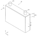
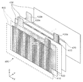
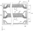
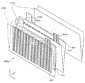
図1は、本発明の実施の形態に係る蓄電素子10の外観を模式的に示す斜視図である。図2は、本発明の実施の形態に係る蓄電素子10の容器100の容器本体111を分離して蓄電素子10が備える各構成要素を示す斜視図である。図3は、図1の蓄電素子10のA−A断面を示す図である。   FIG. 1 is a perspective view schematically showing an external appearance of a power storage device 10 according to an embodiment of the present invention. FIG. 2 is a perspective view showing components included in power storage element 10 by separating container body 111 of container 100 of power storage element 10 according to the embodiment of the present invention. FIG. 3 is a view showing an AA cross section of the electricity storage device 10 of FIG. 1.

蓄電素子10は、電気を充電し、また、電気を放電することのできる二次電池であり、より具体的には、リチウムイオン二次電池などの非水電解質二次電池である。なお、蓄電素子10は、非水電解質二次電池には限定されず、非水電解質二次電池以外の二次電池であってもよいし、キャパシタであってもよい。   The power storage element 10 is a secondary battery that can charge electricity and discharge electricity, and more specifically, is a non-aqueous electrolyte secondary battery such as a lithium ion secondary battery. In addition, the electrical storage element 10 is not limited to a nonaqueous electrolyte secondary battery, A secondary battery other than a nonaqueous electrolyte secondary battery may be sufficient, and a capacitor may be sufficient as it.

これらの図に示すように、蓄電素子10は、容器100と、正極端子200と、負極端子300とを備えている。また、容器100内方には、正極集電体120と、負極集電体130と、電極体400と、規制部材500とが収容されている。蓄電素子10の容器100の内部には電解液(非水電解質)などの液体が封入されているが、当該液体の図示は省略する。なお、容器100に封入される電解液としては、蓄電素子10の性能を損なうものでなければその種類に特に制限はなく様々なものを選択することができる。   As shown in these drawings, the electricity storage device 10 includes a container 100, a positive electrode terminal 200, and a negative electrode terminal 300. In addition, a positive electrode current collector 120, a negative electrode current collector 130, an electrode body 400, and a regulating member 500 are accommodated inside the container 100. A liquid such as an electrolytic solution (non-aqueous electrolyte) is sealed inside the container 100 of the electricity storage element 10, but the illustration of the liquid is omitted. In addition, as long as it does not impair the performance of the electrical storage element 10, as the electrolyte solution enclosed with the container 100, there is no restriction | limiting in particular and various things can be selected.

容器100は、矩形筒状で底部を備える容器本体111と、容器本体111の開口を閉塞する板状部材である蓋体110とで構成されている。ここで、容器本体111の底部と、蓋体110とは、互いに対向している。また、容器100は、電極体400および規制部材500等を内部に収容後、蓋体110と容器本体111とが溶接等されることにより、内部を密封することができるものとなっている。なお、蓋体110および容器本体111の材質は、特に限定されないが、例えばステンレス鋼、アルミニウム、アルミニウム合金など溶接可能な金属であるのが好ましい。   The container 100 includes a container body 111 having a rectangular cylindrical shape and a bottom, and a lid body 110 that is a plate-like member that closes the opening of the container body 111. Here, the bottom of the container body 111 and the lid 110 face each other. In addition, the container 100 can be hermetically sealed by welding the lid body 110 and the container main body 111 after the electrode body 400 and the regulating member 500 are accommodated therein. The material of the lid 110 and the container body 111 is not particularly limited, but is preferably a weldable metal such as stainless steel, aluminum, aluminum alloy, for example.

電極体400は、正極410と負極420とセパレータ430とを備え、電気を蓄えることができる部材である。具体的には、正極410は、アルミニウムやアルミニウム合金などからなる矩形状の金属箔である正極基材層上に正極活物質層が形成されたものである。また、負極420は、銅や銅合金などからなる矩形状の金属箔である負極基材層上に負極活物質層が形成されたものである。また、セパレータ430は、樹脂からなる矩形状の微多孔性のシートである。電極体400の具体的な構成については、図4を用いて説明する。なお、図3に示すように、一点鎖線で示す負極420は、破線で示す正極410よりも積層方向(Y軸方向)から見て平面視における面積が大きい。また、図3において実線で示すセパレータ430は、正極410および負極420が互いに短絡することを防ぐために、正極410および負極420よりも積層方向(Y軸方向)から見て平面視における面積が大きく、かつ、各端辺が、正極410および負極420の端辺(ただし正極接続部411および負極接続部421を除く)よりも外側に配置されるように積層されている。ここで、セパレータ430の端辺とは、各セパレータの端部分であり、各極板からはみ出た部分のことを指す。   The electrode body 400 includes a positive electrode 410, a negative electrode 420, and a separator 430, and is a member that can store electricity. Specifically, the positive electrode 410 is obtained by forming a positive electrode active material layer on a positive electrode base material layer that is a rectangular metal foil made of aluminum or an aluminum alloy. In addition, the negative electrode 420 is obtained by forming a negative electrode active material layer on a negative electrode base material layer that is a rectangular metal foil made of copper, a copper alloy, or the like. The separator 430 is a rectangular microporous sheet made of resin. A specific configuration of the electrode body 400 will be described with reference to FIG. Note that, as shown in FIG. 3, the negative electrode 420 indicated by the alternate long and short dash line has a larger area in plan view as viewed from the stacking direction (Y-axis direction) than the positive electrode 410 indicated by the broken line. Further, the separator 430 indicated by a solid line in FIG. 3 has a larger area in a plan view than the positive electrode 410 and the negative electrode 420 as viewed from the stacking direction (Y-axis direction) in order to prevent the positive electrode 410 and the negative electrode 420 from short-circuiting each other. And each edge is laminated | stacked so that it may arrange | position outside the edge (except for the positive electrode connection part 411 and the negative electrode connection part 421) of the positive electrode 410 and the negative electrode 420. Here, the end side of the separator 430 is an end portion of each separator, and refers to a portion protruding from each electrode plate.

図4は、電極体400の構造を説明するための図である。具体的には、図4は、電極体400を構成している正極410、負極420、およびセパレータ430の分解斜視図である。なお、図4では、正極410および負極420を図示するために、手前側(Y軸方向マイナス側)に配置される、2枚のセパレータ430を破線で示している。   FIG. 4 is a diagram for explaining the structure of the electrode body 400. Specifically, FIG. 4 is an exploded perspective view of the positive electrode 410, the negative electrode 420, and the separator 430 constituting the electrode body 400. In FIG. 4, in order to illustrate the positive electrode 410 and the negative electrode 420, two separators 430 arranged on the front side (minus side in the Y-axis direction) are indicated by broken lines.

電極体400は、図4に示すように、複数の正極410および複数の負極420が交互に積層された複数の極板のそれぞれの間に、複数のセパレータ430が配置されることにより構成される。具体的には、電極体400は、セパレータ430と、正極410と、セパレータ430と、負極420とがこの順に繰り返し積層されることにより構成される。つまり、電極体400は、複数の平板状の極板が積層された積層型(スタック型)の電極体である。   As shown in FIG. 4, the electrode body 400 is configured by disposing a plurality of separators 430 between a plurality of electrode plates in which a plurality of positive electrodes 410 and a plurality of negative electrodes 420 are alternately stacked. . Specifically, the electrode body 400 is configured by repeatedly laminating a separator 430, a positive electrode 410, a separator 430, and a negative electrode 420 in this order. That is, the electrode body 400 is a stacked (stacked) electrode body in which a plurality of flat plate plates are stacked.

正極410は、アルミニウムやアルミニウム合金などからなる矩形平板状の正極基材層の両表面に、正極活物質層が形成されたものである。なお、本発明に係る蓄電素子10に用いられる正極410は、特に従来用いられてきたものと異なるところはなく、通常用いられているものが使用できる。   The positive electrode 410 is obtained by forming a positive electrode active material layer on both surfaces of a rectangular flat plate-shaped positive electrode base material layer made of aluminum or an aluminum alloy. In addition, the positive electrode 410 used for the electrical storage element 10 according to the present invention is not particularly different from those conventionally used, and those normally used can be used.

例えば、正極活物質としては、LiMPO、LiMSiO、LiMBO(MはFe、Ni、Mn、Co等から選択される1種または2種以上の遷移金属元素)等のポリアニオン化合物、チタン酸リチウム、マンガン酸リチウム等のスピネル化合物、Li1+α1−α(0≦α<1、MはFe、Ni、Mn、Co等から選択される1種または2種以上の遷移金属元素)等のリチウム遷移金属酸化物等を用いることができる。 For example, as the positive electrode active material, polyanion compounds such as LiMPO 4 , Li 2 MSiO 4 , LiMBO 3 (M is one or more transition metal elements selected from Fe, Ni, Mn, Co, etc.), titanium, etc. Spinel compounds such as lithium oxide and lithium manganate, Li 1 + α M 1-α O 2 (0 ≦ α <1, M is one or more transition metal elements selected from Fe, Ni, Mn, Co, etc. Lithium transition metal oxides such as) can be used.

負極420は、銅や銅合金などからなる矩形平板状の負極基材の両表面に、負極活物質層が形成されたものである。なお、本発明に係る蓄電素子10に用いられる負極420は、特に従来用いられてきたものと異なるところはなく、通常用いられているものが使用できる。   The negative electrode 420 is formed by forming a negative electrode active material layer on both surfaces of a rectangular flat plate-shaped negative electrode substrate made of copper, a copper alloy, or the like. In addition, the negative electrode 420 used for the electrical storage element 10 according to the present invention is not particularly different from that conventionally used, and a commonly used one can be used.

例えば、負極活物質としては、リチウムイオンを吸蔵放出可能な負極活物質であれば、適宜公知の材料を使用できる。例えば、リチウム金属、リチウム合金(リチウム−アルミニウム、リチウム−鉛、リチウム−錫、リチウム−アルミニウム−錫、リチウム−ガリウム、およびウッド合金等のリチウム金属含有合金)の他、リチウムを吸蔵・放出可能な合金、炭素材料(例えば黒鉛、難黒鉛化炭素、易黒鉛化炭素、低温焼成炭素、非晶質カーボン等)、金属酸化物、リチウム金属酸化物(LiTi12等)、ポリリン酸化合物などが挙げられる。 For example, as the negative electrode active material, a known material can be appropriately used as long as it is a negative electrode active material capable of occluding and releasing lithium ions. For example, lithium metal and lithium alloys (lithium metal-containing alloys such as lithium-aluminum, lithium-lead, lithium-tin, lithium-aluminum-tin, lithium-gallium, and wood alloys) and lithium can be occluded / released. Alloy, carbon material (eg, graphite, non-graphitizable carbon, graphitizable carbon, low-temperature calcined carbon, amorphous carbon, etc.), metal oxide, lithium metal oxide (Li 4 Ti 5 O 12 etc.), polyphosphate compound Etc.

また、正極410には、正極410のX軸方向プラス側の一部からZ軸方向プラス側(上方)に向かって突出している正極タブ410aが形成されている。負極420には、負極420のX軸方向マイナス側の一部からZ軸方向プラス側(上方)に向かって突出している負極タブ420aが形成されている。正極タブ410aおよび負極タブ420aは、セパレータ430のZ軸方向プラス側の端部(上端)よりも上方に突出している。正極タブ410aでは、正極活物質が形成されておらず、正極基材層であるアルミニウム箔が露出している。負極タブ420aでは、負極活物質が形成されておらず、負極基材層である銅箔が露出している。つまり、電極体400の上部におけるX軸方向プラス側の一部は、電極体400の上方に向かって突出しており、かつ、正極基材のみが露出している正極接続部411である。また、電極体400の上部におけるX軸方向マイナス側の一部は、電極体400の上方に向かって突出しており、かつ、負極基材のみが露出している負極接続部421である。つまり、正極接続部411は、正極410の活物質層非形成部が積層されて束ねられた電極体400の一部である。負極接続部421は、負極420の活物質層非形成部が積層されて束ねられた電極体400の他の一部である。   Further, the positive electrode 410 is formed with a positive electrode tab 410a that protrudes from a part on the positive side of the positive side 410 in the X-axis direction plus side (upward) in the Z-axis direction. The negative electrode 420 is formed with a negative electrode tab 420a that protrudes from a part of the negative side of the negative side of the negative side 420 toward the positive side (upward) in the Z-axis direction. The positive electrode tab 410a and the negative electrode tab 420a protrude above the end (upper end) of the separator 430 on the positive side in the Z-axis direction. In the positive electrode tab 410a, the positive electrode active material is not formed, and the aluminum foil as the positive electrode base material layer is exposed. In the negative electrode tab 420a, the negative electrode active material is not formed, and the copper foil as the negative electrode base material layer is exposed. That is, a part of the upper side of the electrode body 400 on the positive side in the X-axis direction is the positive electrode connection portion 411 that protrudes upward from the electrode body 400 and that only the positive electrode base material is exposed. Further, a part of the upper side of the electrode body 400 on the minus side in the X-axis direction is a negative electrode connection portion 421 that protrudes upward from the electrode body 400 and that only the negative electrode base material is exposed. That is, the positive electrode connecting portion 411 is a part of the electrode body 400 in which the active material layer non-forming portions of the positive electrode 410 are stacked and bundled. The negative electrode connecting portion 421 is another part of the electrode body 400 in which the active material layer non-forming portions of the negative electrode 420 are stacked and bundled.

正極集電体120は、電極体400の上方の正極側に配置され、正極端子200と正極接続部411とに電気的に接続される導電性と剛性とを備えた部材である。なお、正極集電体120は、電極体400の正極基材層と同様、アルミニウムまたはアルミニウム合金などで形成されている。具体的には、正極集電体120は、電極体400の正極接続部411に溶接などによって接合されることで、電極体400の正極410と接続される。   The positive electrode current collector 120 is a member that is disposed on the positive electrode side above the electrode body 400 and has electrical conductivity and rigidity that are electrically connected to the positive electrode terminal 200 and the positive electrode connection portion 411. The positive electrode current collector 120 is made of aluminum, an aluminum alloy, or the like, like the positive electrode base material layer of the electrode body 400. Specifically, the positive electrode current collector 120 is connected to the positive electrode 410 of the electrode body 400 by being joined to the positive electrode connection portion 411 of the electrode body 400 by welding or the like.

負極集電体130は、電極体400の上方の負極側に配置され、負極端子300と負極接続部421とに電気的に接続される導電性と剛性とを備えた部材である。なお、負極集電体130は、電極体400の負極基材層と同様、銅または銅合金などで形成されている。具体的には、負極集電体130は、電極体400の負極接続部421に溶接などによって接合されることで、電極体400の負極420と接続される。   The negative electrode current collector 130 is a member that is disposed on the negative electrode side above the electrode body 400 and has electrical conductivity and rigidity that are electrically connected to the negative electrode terminal 300 and the negative electrode connection portion 421. The negative electrode current collector 130 is formed of copper, a copper alloy, or the like, like the negative electrode base material layer of the electrode body 400. Specifically, the negative electrode current collector 130 is connected to the negative electrode 420 of the electrode body 400 by being joined to the negative electrode connection portion 421 of the electrode body 400 by welding or the like.

正極端子200は、電極体400の正極410に電気的に接続された電極端子であり、負極端子300は、電極体400の負極420に電気的に接続された電極端子である。つまり、正極端子200および負極端子300は、電極体400に蓄えられている電気を蓄電素子10の外部空間に導出し、また、電極体400に電気を蓄えるために蓄電素子10の内部空間に電気を導入するための金属製の電極端子である。また、正極端子200および負極端子300は、電極体400の上方に配置された蓋体110に取り付けられている。つまり、正極端子200および負極端子300は、容器100の壁面に設けられている。   The positive electrode terminal 200 is an electrode terminal electrically connected to the positive electrode 410 of the electrode body 400, and the negative electrode terminal 300 is an electrode terminal electrically connected to the negative electrode 420 of the electrode body 400. That is, the positive electrode terminal 200 and the negative electrode terminal 300 lead the electricity stored in the electrode body 400 to the external space of the power storage element 10, and in order to store the electricity in the electrode body 400, It is an electrode terminal made of metal for introducing. Further, the positive electrode terminal 200 and the negative electrode terminal 300 are attached to the lid body 110 disposed above the electrode body 400. That is, the positive electrode terminal 200 and the negative electrode terminal 300 are provided on the wall surface of the container 100.

なお、正極集電体120および負極集電体130は、それぞれ、正極端子200および負極端子300とは別体の構造物であってもよいし、正極端子200および負極端子300の一部であってもよい。   The positive electrode current collector 120 and the negative electrode current collector 130 may be separate structures from the positive electrode terminal 200 and the negative electrode terminal 300, respectively, or may be part of the positive electrode terminal 200 and the negative electrode terminal 300. May be.

複数のセパレータ430は、端辺が規制部材500に固定されている。具体的には、複数のセパレータ430は、複数の正極410および複数の負極420とともに積層された状態(図4参照)で、互いに対向している2つの端辺(つまりここではX軸方向の両側の端辺)において規制部材500に固定されている。   The end sides of the plurality of separators 430 are fixed to the regulating member 500. Specifically, the plurality of separators 430 are stacked together with the plurality of positive electrodes 410 and the plurality of negative electrodes 420 (see FIG. 4), and two end sides facing each other (that is, both sides in the X-axis direction here). Is fixed to the restricting member 500 at the end side.

規制部材500は、セパレータ430の一部が固定された部材であって、容器100に対する移動が規制されている部材である。なお、ここで言う、セパレータ430の一部とは、具体的には、上述したように、セパレータ430のX軸方向の両側の端辺である。電極体400と規制部材500とは、固定されることにより一体化されている。また、規制部材500は、Y軸方向に分離された複数の部材により構成されている。具体的には、規制部材500は、第一規制部材510、第二規制部材520および第三規制部材530により構成されている。規制部材500は、絶縁性を有する材料により構成されており、例えば、PE(ポリエチレン)、PP(ポリプロピレン)、ABS(アクリロニトリルブタジエンスチレン)、PET(ポリエチレンテレフタレート)、PPS(ポリフェニレンスルファイド)などの樹脂を用いることができる。なかでもPE(ポリエチレン)、PP(ポリプロピレン)が好適である。また、セパレータと規制部材とを熱溶着により固定する場合には、セパレータと融点が近い材料で規制部材を構成することで、熱溶着による固定が容易になる。   The regulating member 500 is a member to which a part of the separator 430 is fixed, and the movement with respect to the container 100 is regulated. The part of the separator 430 referred to here is specifically the side edges on both sides of the separator 430 in the X-axis direction as described above. The electrode body 400 and the regulating member 500 are integrated by being fixed. The restricting member 500 is composed of a plurality of members separated in the Y-axis direction. Specifically, the restriction member 500 includes a first restriction member 510, a second restriction member 520, and a third restriction member 530. The regulating member 500 is made of an insulating material, and for example, a resin such as PE (polyethylene), PP (polypropylene), ABS (acrylonitrile butadiene styrene), PET (polyethylene terephthalate), PPS (polyphenylene sulfide), and the like. Can be used. Of these, PE (polyethylene) and PP (polypropylene) are preferred. Moreover, when fixing a separator and a control member by heat welding, fixation by heat welding becomes easy by comprising a control member with the material with melting | fusing point close | similar to a separator.

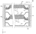
図5は、図1の蓄電素子10のB−B断面を示す図である。   FIG. 5 is a diagram showing a BB cross section of the electricity storage device 10 of FIG. 1.

同図に示すように、電極体400は、複数の正極410、複数の負極420および複数のセパレータ430が積層された第一の端辺束401および第二の端辺束402から構成される2つのの端辺束を有している。第一の端辺束401および第二の端辺束402は、それぞれ、第一規制部材510および第二規制部材520に固定されている。第一の端辺束401および第二の端辺束402は、第一規制部材510および第二規制部材520が互いに固定されることにより、一体化されている。また、規制部材500は、第一規制部材510、第二規制部材520および第三規制部材530が、複数のセパレータ430が束ねられた固定部分431、432を介して接合されることにより、構成されている。   As shown in the figure, the electrode body 400 includes a first end bundle 401 and a second end bundle 402 in which a plurality of positive electrodes 410, a plurality of negative electrodes 420, and a plurality of separators 430 are stacked. It has two edge bundles. The first edge bundle 401 and the second edge bundle 402 are fixed to the first restriction member 510 and the second restriction member 520, respectively. The first edge bundle 401 and the second edge bundle 402 are integrated by fixing the first restriction member 510 and the second restriction member 520 to each other. The restricting member 500 is configured by joining the first restricting member 510, the second restricting member 520, and the third restricting member 530 via fixed portions 431 and 432 in which a plurality of separators 430 are bundled. ing.

規制部材500は、容器100にZ軸方向およびY軸方向で当接することにより、容器100に対する移動が規制されている。具体的には、規制部材500は、容器100のX軸方向側の側面(短側面)に沿って配置される板状部材である。規制部材500は、容器100に対して少なくとも一部が当接している。   The restriction member 500 is restricted from moving with respect to the container 100 by contacting the container 100 in the Z-axis direction and the Y-axis direction. Specifically, the regulating member 500 is a plate-like member disposed along the side surface (short side surface) of the container 100 on the X axis direction side. The regulating member 500 is at least partially in contact with the container 100.

なお、規制部材500は、厳密に容器100に当接していなくてもよく、例えば、蓄電素子10に振動または衝撃が加えられたときに、容器100に当接することで、電極体400の容器100に対する移動を規制できればよい。つまり、規制部材500は、常に容器100に当接した状態でなくてもよい。具体的には、規制部材500は、容器100の内部空間のY軸方向およびZ軸方向それぞれにおける幅に対して、それぞれ95%以上の幅を有していれば容器100に対する電極体400のY軸方向およびZ軸方向に向かう移動を規制することができ、同様に98%以上の幅を有していればより好ましい。さらに言えば、規制部材500は、容器100に、Y軸方向およびZ軸方向の両端が当接した状態で収容されていることがより好ましい。なお、規制部材500は、Y軸方向およびZ軸方向のいずれか一方で容器100に当接すれば、いずれかの方向における電極体400の移動を規制することができる。特に、規制部材500は、少なくともZ軸方向に沿った移動が規制されるように、容器100の底部または蓋体110に当接する構成であることがより好ましい。本実施の形態においては、Y軸方向およびZ軸方向の両方で容器に当接しているため、電極体400の容器100に対する移動をより強固に規制することができる。   Note that the regulating member 500 may not strictly contact the container 100. For example, the container 100 of the electrode body 400 is brought into contact with the container 100 when vibration or impact is applied to the power storage element 10. What is necessary is just to be able to regulate movement with respect to. That is, the regulating member 500 may not always be in contact with the container 100. Specifically, if the regulating member 500 has a width of 95% or more with respect to the width in the Y-axis direction and the Z-axis direction of the internal space of the container 100, the Y of the electrode body 400 with respect to the container 100 Movement in the axial direction and the Z-axis direction can be restricted, and similarly, it is more preferable if it has a width of 98% or more. Furthermore, it is more preferable that the regulating member 500 is accommodated in the container 100 in a state where both ends in the Y-axis direction and the Z-axis direction are in contact. The restricting member 500 can restrict the movement of the electrode body 400 in either direction as long as it contacts the container 100 in either the Y-axis direction or the Z-axis direction. In particular, the restriction member 500 is more preferably configured to abut against the bottom of the container 100 or the lid 110 so that movement along at least the Z-axis direction is restricted. In the present embodiment, since the container is in contact with both the Y-axis direction and the Z-axis direction, the movement of the electrode body 400 relative to the container 100 can be more firmly regulated.

次に、図6〜図10を用いて、電極体400と規制部材500との固定について具体的に説明する。   Next, the fixing of the electrode body 400 and the regulating member 500 will be specifically described with reference to FIGS.

図6は、積層された電極体400の第一の端辺束401の規制部材500への固定方法を説明するための図である。図7は、電極体400をY軸方向からみた場合の平面図である。図7は、具体的には、規制部材500に固定された電極体400のうち規制部材500を省略して示した図である。図8Aは、第一の端辺束401と第一規制部材510との固定部分の一例を示す斜視図である。図8Bは、第一の端辺束401と第一規制部材510との固定部分の他の一例を示す斜視図である。図9は、第一の端辺束401が固定された第一規制部材510と、第二の端辺束402が固定された第二規制部材520と、第三規制部材530との固定方法を説明するための斜視図である。図10は、電極体400と規制部材500とが固定されることにより一体化された組立体を示す斜視図である。   FIG. 6 is a view for explaining a method of fixing the first end bundle 401 of the stacked electrode body 400 to the regulating member 500. FIG. 7 is a plan view of the electrode body 400 when viewed from the Y-axis direction. Specifically, FIG. 7 is a diagram in which the regulating member 500 is omitted from the electrode body 400 fixed to the regulating member 500. FIG. 8A is a perspective view showing an example of a fixed portion between the first edge bundle 401 and the first regulating member 510. FIG. 8B is a perspective view showing another example of a fixing portion between the first edge bundle 401 and the first regulating member 510. 9 shows a method of fixing the first regulating member 510 to which the first edge bundle 401 is fixed, the second regulating member 520 to which the second edge bundle 402 is fixed, and the third regulating member 530. It is a perspective view for demonstrating. FIG. 10 is a perspective view showing an assembly integrated by fixing the electrode body 400 and the regulating member 500.

図6に示すように、図4で説明した電極体400の一部である第一の端辺束401は、第一の端辺束401を構成している複数のセパレータ430のX軸方向の両端の固定部分431が、第一規制部材510と熱溶着されることにより、第一規制部材510と固定されている。このとき、複数のセパレータ430の間に正極410または負極420が配置された状態で、複数のセパレータ430のX軸方向の両端の固定部分431が第一規制部材510に対して熱溶着により固定されている。このため、複数の極板を含む第一の端辺束401は、第一規制部材510に対して固定されている。   As shown in FIG. 6, the first edge bundle 401 that is a part of the electrode assembly 400 described in FIG. 4 is the X-axis direction of the plurality of separators 430 constituting the first edge bundle 401. The fixing portions 431 at both ends are fixed to the first regulating member 510 by being thermally welded to the first regulating member 510. At this time, in a state where the positive electrode 410 or the negative electrode 420 is disposed between the plurality of separators 430, the fixing portions 431 at both ends in the X-axis direction of the plurality of separators 430 are fixed to the first regulating member 510 by heat welding. ing. For this reason, the first edge bundle 401 including a plurality of electrode plates is fixed to the first regulating member 510.

また、固定部分431は、図5〜7に示すように、正極410および負極420と対向していない。つまり、規制部材500を構成する第一規制部材510、第二規制部材520および第三規制部材530の間には、正極410および負極420は、配置されていない。このように、固定部分431が正極410および負極420に対向しない部分であるため、複数のセパレータ430を直接重ねた状態で規制部材500に熱溶着することができる。このため、セパレータ430の規制部材500への熱溶着をより確実にできる。   In addition, the fixed portion 431 does not face the positive electrode 410 and the negative electrode 420 as shown in FIGS. That is, the positive electrode 410 and the negative electrode 420 are not disposed between the first restriction member 510, the second restriction member 520, and the third restriction member 530 constituting the restriction member 500. As described above, since the fixed portion 431 is a portion that does not face the positive electrode 410 and the negative electrode 420, the plurality of separators 430 can be thermally welded to the regulating member 500 in a state of being directly stacked. For this reason, the thermal welding of the separator 430 to the regulating member 500 can be more reliably performed.

なお、第一の端辺束401は、図8Aに示すように、第一規制部材510のY軸方向マイナス側の面の全体にわたる被固定部511で溶着されている。また、第一の端辺束401は、図8Bに示すように、離散的に設けられる複数の被固定部511aで溶着されていてもよい。なお、上記の例の他にも、固定部は、複数の点状の溶着箇所が平面状に広がるように溶着されてもよいし、複数の線状の溶着箇所が平面状に広がるように溶着されてもよい。   As shown in FIG. 8A, the first edge bundle 401 is welded by a fixed portion 511 that covers the entire surface of the first regulating member 510 on the negative side in the Y-axis direction. Further, as shown in FIG. 8B, the first edge bundle 401 may be welded by a plurality of fixed portions 511a provided discretely. In addition to the above example, the fixing portion may be welded so that a plurality of spot-like welding locations spreads in a planar shape, or welded so that a plurality of linear welding locations spreads in a planar shape. May be.

セパレータ430の他の一部である第二の端辺束402は、第一の端辺束401と同様にして、第二の端辺束402を構成している複数のセパレータ430のX軸方向の両端の固定部分432が、第二規制部材520のY軸方向マイナス側の面と熱溶着されることにより、第二規制部材520と固定されている。   The second edge bundle 402, which is another part of the separator 430, is similar to the first edge bundle 401 in the X-axis direction of the plurality of separators 430 constituting the second edge bundle 402. The fixed portions 432 at both ends of the second fixing member 520 are fixed to the second restricting member 520 by being thermally welded to the surface on the negative side in the Y-axis direction of the second restricting member 520.

固定部分431、432が各端辺束401、402のY軸方向の中心に位置するように各端辺束401、402を構成できるように、第一規制部材510、第二規制部材520、および第三規制部材530のY軸方向の幅を設計してもよい。このような構成によれば、各端辺束401、402においてY軸方向外側に配置されるセパレータ430が各規制部材510、520に向けて緩やかに湾曲するように固定することができる。したがって、セパレータ430の、規制部材500との固定箇所付近にかかる物理的な負担を軽減することができる。   The first regulating member 510, the second regulating member 520, and the second regulating member 520, so that the respective edge bundles 401, 402 can be configured such that the fixed portions 431, 432 are positioned in the center of the respective edge bundles 401, 402 in the Y-axis direction The width of the third restriction member 530 in the Y-axis direction may be designed. According to such a configuration, the separator 430 disposed on the outer side in the Y-axis direction in each of the edge bundles 401 and 402 can be fixed so as to be gently curved toward the respective regulating members 510 and 520. Therefore, it is possible to reduce a physical burden on the vicinity of the fixed portion of the separator 430 with the restriction member 500.

図9に示すように、第一の端辺束401が溶着された第一規制部材510と、第二の端辺束402が溶着された第二規制部材520と、第三規制部材530とは、第一の端辺束401の固定部分431および第二の端辺束402の固定部分432をY軸方向で挟み込んで重ねられている。また、第一の端辺束401および第二の端辺束402の間には、正極410および負極420のうちの幅が大きい方の負極420が配置されている。   As shown in FIG. 9, the first regulating member 510 to which the first edge bundle 401 is welded, the second regulating member 520 to which the second edge bundle 402 is welded, and the third regulating member 530 are The fixed portion 431 of the first edge bundle 401 and the fixed portion 432 of the second edge bundle 402 are sandwiched and overlapped in the Y-axis direction. Further, between the first edge bundle 401 and the second edge bundle 402, the negative electrode 420 having the larger width of the positive electrode 410 and the negative electrode 420 is disposed.

また、第一規制部材510、第一の端辺束401の固定部分431、第二規制部材520、第二の端辺束402の固定部分432、および第三規制部材530は、この順に重ねられた状態で、互いに固定されている。具体的には、第一規制部材510、固定部分431、第二規制部材520、固定部分432および第三規制部材530は、X軸方向に面する側面において、複数の溶着面540(図10を参照)で熱溶着されることにより互いに固定されている。なお、この場合の複数の溶着面540のそれぞれは、第一規制部材510、第一の端辺束401の固定部分431、第二規制部材520、第二の端辺束402の固定部分432、および第三規制部材530に跨がって形成される面である。つまり、溶着面540は、第一規制部材510、第一の端辺束401の固定部分431、第二規制部材520、第二の端辺束402の固定部分431、および第三規制部材530は、それぞれが、Y軸方向にわたって溶着により溶かし込まれて、結合することにより形成されている。   The first restricting member 510, the fixed portion 431 of the first edge bundle 401, the second restricting member 520, the fixed portion 432 of the second edge bundle 402, and the third restricting member 530 are stacked in this order. Are fixed to each other. Specifically, the first restricting member 510, the fixed portion 431, the second restricting member 520, the fixed portion 432, and the third restricting member 530 have a plurality of welding surfaces 540 (see FIG. 10) on the side faces facing the X-axis direction. Are fixed to each other by heat welding. Each of the plurality of welding surfaces 540 in this case includes a first regulating member 510, a fixed portion 431 of the first edge bundle 401, a second regulating member 520, and a fixed portion 432 of the second edge bundle 402, And a surface formed across the third regulating member 530. That is, the welding surface 540 includes the first regulating member 510, the fixed portion 431 of the first edge bundle 401, the second regulating member 520, the fixed portion 431 of the second edge bundle 402, and the third regulating member 530. , Each is formed by welding and bonding over the Y-axis direction.

なお、本実施の形態においては、第一の端辺束401および第二の端辺束402は、第一規制部材510および第二規制部材520のY軸方向マイナス側の面に固定されているが、Y軸方向プラス側の面や、X軸方向の面に固定されてもよい。すなわち、規制部材に固定ができれば、固定される面の方向は問わない。また、固定部分431および432は、第一規制部材510、第二規制部材520および第三規制部材530によってY軸方向で挟み込まれていなくともよく、溶着面540に固定部分431および432が含まれなくともよい。   In the present embodiment, the first edge bundle 401 and the second edge bundle 402 are fixed to the negative side surface of the first restriction member 510 and the second restriction member 520 in the Y-axis direction. However, it may be fixed to the surface on the Y axis direction plus side or the surface in the X axis direction. That is, the direction of the surface to be fixed is not limited as long as it can be fixed to the regulating member. Further, the fixed portions 431 and 432 may not be sandwiched in the Y-axis direction by the first restricting member 510, the second restricting member 520, and the third restricting member 530, and the fixing portions 431 and 432 are included in the welding surface 540. Not necessary.

本実施の形態に係る蓄電素子10によれば、電極体400を構成するセパレータ430の一部が規制部材500に固定されており、かつ、容器100に対する規制部材500の移動が規制されているため、蓄電素子10に振動や衝撃が加わった場合であっても、電極体400が容器100に対して動くことを抑制できる。これにより、蓄電素子10の性能低下や内部短絡の発生を防ぐことができる。   According to the electricity storage device 10 according to the present exemplary embodiment, a part of the separator 430 constituting the electrode body 400 is fixed to the regulating member 500, and the movement of the regulating member 500 with respect to the container 100 is regulated. Even when the storage element 10 is subjected to vibration or impact, the electrode body 400 can be prevented from moving relative to the container 100. Thereby, the performance degradation of the electrical storage element 10 and generation | occurrence | production of an internal short circuit can be prevented.

また、本実施の形態に係る蓄電素子10によれば、規制部材500は、容器100に当接することにより、容器100に対する電極体400の移動を規制する。このため、電極体400が容器100に対して動くことを確実に抑制できる。   Further, according to the electricity storage device 10 according to the present exemplary embodiment, the regulating member 500 regulates the movement of the electrode body 400 relative to the container 100 by contacting the container 100. For this reason, it can suppress reliably that the electrode body 400 moves with respect to the container 100. FIG.

また、本実施の形態に係る蓄電素子10によれば、容器100と電極体400との間には、電極端子200、300との接続部分を形成するための空間があるため、電極体400は、容器100の、電極端子200、300が設けられる壁面に交差する方向に移動しやすい。本実施の形態に係る蓄電素子10によれば、規制部材500のように、容器100の、電極端子200、300が設けられる壁面(つまり、容器本体111の底部または蓋体110)に当接する構成の規制部材を採用することにより、電極体400の容器100に対する移動を効果的に抑制できる。なお、ここで言う、電極端子200、300が設けられる壁面に交差する方向とは、壁面に直交する方向であり、壁面に直交する方向からずれた方向であってもよい。つまり、壁面に交差する方向は、壁面に平行な方向を含まない。   Moreover, according to the electrical storage element 10 according to the present embodiment, since there is a space between the container 100 and the electrode body 400 for forming a connection portion with the electrode terminals 200 and 300, the electrode body 400 is The container 100 can easily move in a direction intersecting the wall surface on which the electrode terminals 200 and 300 are provided. According to the electricity storage device 10 according to the present embodiment, like the regulating member 500, the container 100 is in contact with the wall surface on which the electrode terminals 200 and 300 are provided (that is, the bottom of the container body 111 or the lid 110). By adopting this restriction member, the movement of the electrode body 400 relative to the container 100 can be effectively suppressed. Here, the direction intersecting the wall surface on which the electrode terminals 200 and 300 are provided is a direction orthogonal to the wall surface, and may be a direction shifted from the direction orthogonal to the wall surface. That is, the direction intersecting the wall surface does not include a direction parallel to the wall surface.

また、本実施の形態に係る蓄電素子10によれば、規制部材500に対して電極体400が固定されており、規制部材500は、電極体400のX軸方向の両側を覆うように配置されている。また、さらに、規制部材500は、容器100のY軸方向に対向する壁面に沿った形状である。このように、規制部材500は、電極体400が固定されており、かつ、容器100に沿った形状を有するため、電極体400を容器100の内方へ挿入する際のガイドとして機能することもできる。このため、容器100に対する電極体400の挿入を容易にできる。   In addition, according to power storage device 10 according to the present exemplary embodiment, electrode body 400 is fixed to regulating member 500, and regulating member 500 is disposed so as to cover both sides of electrode body 400 in the X-axis direction. ing. Furthermore, the regulating member 500 has a shape along the wall surface of the container 100 facing the Y-axis direction. Thus, since the electrode member 400 is fixed and the regulating member 500 has a shape along the container 100, the restricting member 500 may function as a guide when the electrode body 400 is inserted into the container 100. it can. For this reason, the electrode body 400 can be easily inserted into the container 100.

また、本実施の形態に係る蓄電素子10によれば、規制部材500とセパレータ430の一部とは、熱溶着により固定されている。このため、締結部材などの別部材を用いることなく、規制部材500とセパレータ430の一部とを容易に、かつ、強固に固定することができる。   Moreover, according to the electrical storage element 10 according to the present embodiment, the regulating member 500 and a part of the separator 430 are fixed by thermal welding. For this reason, the regulating member 500 and a part of the separator 430 can be easily and firmly fixed without using another member such as a fastening member.

また、本実施の形態に係る蓄電素子10によれば、セパレータ430の固定部分431、432のそれぞれが規制部材500の第一規制部材510および第二規制部材520において固定されるため、規制部材500の固定される部分における、積層して固定されるセパレータ430の数を少なくすることができる。これにより、複数のセパレータ430と規制部材500とが固定される部分における固定強度を向上できる。   In addition, according to power storage device 10 according to the present exemplary embodiment, each of fixing portions 431 and 432 of separator 430 is fixed at first restriction member 510 and second restriction member 520 of restriction member 500, and therefore, restriction member 500. It is possible to reduce the number of separators 430 that are stacked and fixed in the fixed portion. Thereby, the fixing strength in the part to which the some separator 430 and the control member 500 are fixed can be improved.

また、本実施の形態に係る蓄電素子10によれば、規制部材500は、セパレータ430の一部である固定部分431と固定される第一規制部材510および第二規制部材520を含み、第一規制部材510、第二規制部材520および第三規制部材530は、互いに熱溶着により固定されている。このように、規制部材500を構成する複数の規制部材510、520毎に、複数のセパレータ430の固定部分431を固定すればよいため、複数のセパレータ430の固定部分431および複数の規制部材510、520を容易に固定できる。また、複数の部材510、520、530が互いに固定されているため、複数の部材510、520、530が別々に容器100に対して動くことを抑制できる。   In addition, according to the electricity storage device 10 according to the present exemplary embodiment, the regulating member 500 includes the first regulating member 510 and the second regulating member 520 that are fixed to the fixing portion 431 that is a part of the separator 430, and the first The restricting member 510, the second restricting member 520, and the third restricting member 530 are fixed to each other by heat welding. In this way, since the fixing portions 431 of the plurality of separators 430 may be fixed for each of the plurality of restriction members 510 and 520 constituting the restriction member 500, the fixing portions 431 of the plurality of separators 430 and the plurality of restriction members 510, 520 can be easily fixed. In addition, since the plurality of members 510, 520, and 530 are fixed to each other, the plurality of members 510, 520, and 530 can be prevented from moving with respect to the container 100 separately.

また、本実施の形態に係る蓄電素子10によれば、電極体400は、正極410、負極420、およびセパレータ430が積層された第一の端辺束401および第二の端辺束402を有しており、第一の端辺束401および第二の端辺束402の間には、極板のうちで幅が大きい方の負極420が配置されている。このため、電極体400の第一の端辺束401および第二の端辺束402のそれぞれにおいて、第一の端辺束401および第二の端辺束402の間に配置される当該極板に隣接しているセパレータ430が規制部材500との固定箇所に向けて急激に湾曲することを低減できる。このため、当該セパレータのうちの規制部材500との固定箇所付近にかかる物理的な負担を軽減することができる。   In addition, according to power storage device 10 according to the present exemplary embodiment, electrode body 400 has first edge bundle 401 and second edge bundle 402 in which positive electrode 410, negative electrode 420, and separator 430 are stacked. The negative electrode 420 having a larger width among the electrode plates is disposed between the first end bundle 401 and the second end bundle 402. Therefore, in each of the first edge bundle 401 and the second edge bundle 402 of the electrode body 400, the electrode plate disposed between the first edge bundle 401 and the second edge bundle 402, respectively. It can reduce that the separator 430 which adjoins is curving rapidly toward the fixing | fixed location with the control member 500. FIG. For this reason, the physical burden concerning the fixed location with the control member 500 among the said separator can be reduced.

また、本実施の形態に係る蓄電素子10によれば、規制部材500は、絶縁性を有する材料により構成される。このため、容器100と電極体400との間を確実に絶縁できる。   Moreover, according to the electrical storage element 10 which concerns on this Embodiment, the control member 500 is comprised with the material which has insulation. For this reason, between the container 100 and the electrode body 400 can be insulated reliably.

(変形例1)
次に、実施の形態の変形例1について、説明する。図11は、本発明の実施の形態の変形例1に係る蓄電素子10aにおける図1のA−A断面に対応する図である。図12は、本発明の実施の形態の変形例1に係る電極体400aをY軸方向からみた場合の平面図である。実施の形態の変形例1に係る蓄電素子10aは、実施の形態の蓄電素子10と比較して、規制部材600がさらに設けられていることが異なる。つまり、図12は、具体的には、規制部材500、600に固定された電極体400aのうち規制部材500、600を省略して示した図である。なお、規制部材600がさらに設けられていること以外の構成は、実施の形態の蓄電素子10と同様であるため説明を省略する。
(Modification 1)
Next, Modification 1 of the embodiment will be described. FIG. 11 is a diagram corresponding to the AA cross section of FIG. 1 in power storage element 10a according to the first modification of the embodiment of the present invention. FIG. 12 is a plan view of an electrode body 400a according to Modification 1 of the embodiment of the present invention as viewed from the Y-axis direction. The power storage element 10a according to the first modification of the embodiment is different from the power storage element 10 of the embodiment in that a regulating member 600 is further provided. That is, FIG. 12 is a diagram in which the regulating members 500 and 600 are omitted from the electrode body 400a fixed to the regulating members 500 and 600. Note that the configuration other than the provision of the regulating member 600 is the same as that of the power storage element 10 of the embodiment, and thus the description thereof is omitted.

具体的には、規制部材600は、電極体400aの複数のセパレータ430の下方に設けられ、複数のセパレータ430の下端の固定部分433(端辺)と熱溶着により固定される。規制部材600は、規制部材500とは、複数のセパレータ430との熱溶着される端辺の位置が異なる。なお、規制部材600の複数のセパレータ430との熱溶着される固定部分433の構成は、実施の形態の規制部材500の構成を適用できるため、説明は省略する。規制部材600は、規制部材500とX軸方向で当接するように構成される。なお、規制部材500および規制部材600は、熱溶着などにより互いに固定されていてもよい。また、規制部材500とZ軸方向で当接するように構成した規制部材を採用してもよい。   Specifically, the regulating member 600 is provided below the plurality of separators 430 of the electrode body 400a, and is fixed to the fixing portions 433 (end sides) at the lower ends of the plurality of separators 430 by heat welding. The regulating member 600 is different from the regulating member 500 in the position of the end side where the plurality of separators 430 are thermally welded. The configuration of the fixing portion 433 that is thermally welded to the plurality of separators 430 of the regulating member 600 can be applied to the configuration of the regulating member 500 according to the embodiment, and thus the description thereof is omitted. The restricting member 600 is configured to contact the restricting member 500 in the X-axis direction. Note that the regulating member 500 and the regulating member 600 may be fixed to each other by heat welding or the like. Moreover, you may employ | adopt the regulating member comprised so that the regulating member 500 might contact | abut in a Z-axis direction.

つまり、実施の形態の変形例1に係る蓄電素子10aでは、規制部材500は、複数のセパレータ430の、X軸方向の両側の端辺を固定している。また、さらに、規制部材600は、複数のセパレータ430のZ軸方向の端辺のうち、正極端子200および負極端子300の反対側(つまり容器100の底部側)の端辺を固定している。このように、実施の形態の変形例1に係る蓄電素子10aでは、複数のセパレータ430が規制部材500、600により3つの端辺で固定されているため、複数のセパレータ430の間に配置される極板(正極410および負極420)が移動することを確実に規制できる。また、電極体400aの三方に配置される規制部材500、600が、それぞれZ軸方向およびX軸方向で容器100に当接するため、電極体400aの容器100に対する移動を複数の方向で規制できる。したがって、電極体400aの容器100に対する移動による、蓄電素子10aへの悪影響を確実に抑制することができる。   That is, in the electricity storage element 10a according to the first modification of the embodiment, the regulating member 500 fixes the ends of the separators 430 on both sides in the X-axis direction. Furthermore, the regulating member 600 fixes the end sides of the plurality of separators 430 in the Z-axis direction opposite to the positive electrode terminal 200 and the negative electrode terminal 300 (that is, the bottom side of the container 100). Thus, in the electrical storage element 10a according to the first modification of the embodiment, the plurality of separators 430 are fixed at the three end sides by the regulating members 500 and 600, and thus are disposed between the plurality of separators 430. It is possible to reliably regulate the movement of the electrode plates (the positive electrode 410 and the negative electrode 420). Further, since the regulating members 500 and 600 arranged on the three sides of the electrode body 400a abut against the container 100 in the Z-axis direction and the X-axis direction, respectively, the movement of the electrode body 400a with respect to the container 100 can be regulated in a plurality of directions. Therefore, it is possible to reliably suppress an adverse effect on the storage element 10a due to the movement of the electrode body 400a with respect to the container 100.

(変形例2)
次に、実施の形態の変形例2について、説明する。図13は、本発明の実施の形態の変形例2に係る蓄電素子10bにおける図1のA−A断面に対応する図である。実施の形態の変形例2に係る蓄電素子10bは、実施の形態の蓄電素子10と比較して、規制部材500がX軸方向に移動することを規制するための規制部112aが設けられた蓋体112を有する容器100aが採用されていることが異なる。なお、蓄電素子10bの蓋体112以外の構成は、実施の形態の蓄電素子10と同様であるため説明を省略する。
(Modification 2)
Next, Modification 2 of the embodiment will be described. FIG. 13 is a diagram corresponding to the AA cross section of FIG. 1 in power storage element 10b according to the second modification of the embodiment of the present invention. The electricity storage device 10b according to the second modification of the embodiment is provided with a restriction portion 112a for restricting the movement of the restriction member 500 in the X-axis direction as compared with the electricity storage device 10 of the embodiment. The difference is that a container 100a having a body 112 is employed. Note that the configuration of the power storage element 10b other than the lid 112 is the same as that of the power storage element 10 of the embodiment, and thus the description thereof is omitted.

具体的には、蓋体112に形成される規制部112aは、Z軸方向マイナス側(下方)に向けて突出し、かつ、Y軸方向に沿って突条に延びる。また、規制部112aは、容器本体111の短側面から規制部材500の厚みの分だけ離れた位置に形成される。つまり、規制部材500は、規制部112aと容器本体111の短側面との間に設けられることになるため、容器100aに対する容器本体111に対する移動が規制される。このように、蓋体112に規制部112aを設けることにより、容器100aの内方空間のうちの上部において規制部材500のX軸方向に沿った移動を規制できるため、容器100aに対する電極体400の移動を効果的に規制できる。なお、変形例1の規制部材600をさらに組み合わせれば、容器100aに対する電極体400の移動をより効果的に規制できる。   Specifically, the restricting portion 112a formed on the lid body 112 protrudes toward the minus side (downward) in the Z-axis direction and extends to the ridge along the Y-axis direction. Further, the restricting portion 112 a is formed at a position separated from the short side surface of the container main body 111 by the thickness of the restricting member 500. That is, since the restricting member 500 is provided between the restricting portion 112a and the short side surface of the container main body 111, movement of the container 100a relative to the container main body 111 is restricted. Thus, by providing the restricting portion 112a on the lid body 112, the movement of the restricting member 500 along the X-axis direction can be restricted in the upper part of the inner space of the container 100a. Movement can be regulated effectively. In addition, if the regulating member 600 of the first modification is further combined, the movement of the electrode body 400 relative to the container 100a can be more effectively regulated.

(変形例3)
次に、実施の形態の変形例3について、説明する。図14は、本発明の実施の形態の変形例3に係る蓄電素子10cにおける図1のB−B断面に対応する図である。実施の形態の変形例3に係る蓄電素子10cは、実施の形態の蓄電素子10と比較して、規制部材700の構成が異なる。なお、規制部材700以外の構成は、実施の形態の蓄電素子10の構成と同様であるため説明を省略する。
(Modification 3)
Next, Modification 3 of the embodiment will be described. FIG. 14 is a diagram corresponding to the BB cross section of FIG. 1 in power storage element 10c according to modification 3 of the embodiment of the present invention. The power storage element 10c according to the third modification of the embodiment is different in the configuration of the regulating member 700 from the power storage element 10 according to the embodiment. Since the configuration other than the regulating member 700 is the same as the configuration of the power storage element 10 of the embodiment, the description thereof is omitted.

具体的には、規制部材700は、1つの部材から構成されている点が、実施の形態の規制部材500とは異なる。規制部材700は、容器100のX軸方向側の短側面に沿って配置されている1枚の板状部材701から、容器100の内方に向かってX軸方向に突出する突出部702、703を有する。突出部702、703は、Z軸方向にわたって突条に延びるように、板状部材701に形成されている。また、突出部702、703は、Y軸方向に互いに離間した状態で形成されている。   Specifically, the restriction member 700 is different from the restriction member 500 of the embodiment in that the restriction member 700 is composed of one member. The restricting member 700 is protruded in the X-axis direction toward the inside of the container 100 from one plate-like member 701 disposed along the short side surface on the X-axis direction side of the container 100. Have The protrusions 702 and 703 are formed on the plate-like member 701 so as to extend in the protrusions over the Z-axis direction. The protrusions 702 and 703 are formed in a state of being separated from each other in the Y-axis direction.

そして、規制部材700の突出部702のY軸方向マイナス側の面に、電極体400の第一の端辺束401の固定部分431が熱溶着により固定され、突出部703のY軸方向マイナス側の面に、電極体400の第二の端辺束402の固定部分432が熱溶着により固定される。このように、Y軸方向に分離されていない規制部材700を用いても、第一の端辺束401および第二の端辺束402から構成される電極体400を固定することができる。よって、一部材により構成される剛性の大きい規制部材700を採用することができるため、第一の端辺束401および第二の端辺束402から構成される電極体400が容器100に対して移動することをより効果的に規制することができる。なお、第一の端辺束401および第二の端辺束402は、規制部材700の突出部702、703のY軸方向マイナス側の面に固定されているが、これに限らずに、Y軸方向プラス側の面や、X軸方向の面に固定されてもよい。   Then, the fixing portion 431 of the first edge bundle 401 of the electrode body 400 is fixed to the surface on the negative side in the Y-axis direction of the protruding portion 702 of the regulating member 700 by heat welding, and the negative side of the protruding portion 703 in the Y-axis direction. The fixed portion 432 of the second edge bundle 402 of the electrode body 400 is fixed to the surface by thermal welding. As described above, even when the regulating member 700 that is not separated in the Y-axis direction is used, the electrode body 400 including the first edge bundle 401 and the second edge bundle 402 can be fixed. Therefore, since the rigid restricting member 700 constituted by one member can be employed, the electrode body 400 constituted by the first edge bundle 401 and the second edge bundle 402 is attached to the container 100. The movement can be more effectively regulated. The first edge bundle 401 and the second edge bundle 402 are fixed to the surface on the minus side in the Y-axis direction of the projecting portions 702 and 703 of the regulating member 700. You may fix to the surface of an axial direction plus side, and the surface of an X-axis direction.

(変形例4)
次に、実施の形態の変形例4について、説明する。図15は、本発明の実施の形態の変形例4に係る電極体400と規制部材800とが固定されることにより一体化された組立体を示す斜視図である。図16は、本発明の実施の形態の変形例4に係る蓄電素子10dにおける図1のB−B断面に対応する図である。実施の形態の変形例4に係る蓄電素子10dは、実施の形態の蓄電素子10と比較して、規制部材800の構成が異なる。なお、規制部材800以外の構成は、実施の形態の蓄電素子10の構成と同様であるため説明を省略する。
(Modification 4)
Next, Modification 4 of the embodiment will be described. FIG. 15 is a perspective view showing an assembly integrated by fixing the electrode body 400 and the regulating member 800 according to Modification 4 of the embodiment of the present invention. FIG. 16 is a diagram corresponding to the BB cross section of FIG. 1 in the electric storage element 10d according to the fourth modification of the embodiment of the present invention. The power storage element 10d according to the fourth modification of the embodiment differs from the power storage element 10 according to the embodiment in the configuration of the regulating member 800. Note that the configuration other than the regulating member 800 is the same as the configuration of the power storage element 10 of the embodiment, and thus description thereof is omitted.

具体的には、規制部材800は、変形例3の規制部材700と同様に1つの部材から構成されている点が、実施の形態の規制部材500とは異なる。規制部材800は、容器100のX軸方向側の短側面に沿って配置されている1枚の板状部材からなる。この板状部材には、Z軸方向に延びる2本のスリット810がY軸方向に並んで形成されている。スリット810は板状部材の厚み方向に貫通している。第一の端辺束401および第二の端辺束402の各固定部分431、432が、それぞれ2本のスリット810を貫通した状態で、各スリット810の内面に熱溶着されることにより固定されている。このように、Y軸方向に分離されておらず、かつ、X軸方向に突出した突出部が設けられていない構成の規制部材800を用いても、第一の端辺束401および第二の端辺束402を固定することができる。また、規制部材800を一部材により構成し、かつ、X軸方向に突出した突出部を設けない構成とすることで、より剛性を大きくしつつ、容器100の内方空間に占める体積を少なくすることができる。このため、電極体400が容器100に対して移動することをより効果的に規制しつつ、蓄電素子10dの容量を大きくすることができる。   Specifically, the restricting member 800 differs from the restricting member 500 of the embodiment in that the restricting member 800 is configured by a single member, similarly to the restricting member 700 of the third modification. The regulating member 800 is composed of a single plate-like member disposed along the short side surface of the container 100 on the X-axis direction side. In this plate-like member, two slits 810 extending in the Z-axis direction are formed side by side in the Y-axis direction. The slit 810 penetrates in the thickness direction of the plate member. The fixed portions 431 and 432 of the first edge bundle 401 and the second edge bundle 402 are fixed by being thermally welded to the inner surface of each slit 810 in a state of passing through the two slits 810, respectively. ing. As described above, even when the restriction member 800 having a configuration that is not separated in the Y-axis direction and is not provided with a protruding portion that protrudes in the X-axis direction, the first edge bundle 401 and the second edge bundle 401 The edge bundle 402 can be fixed. Further, the restricting member 800 is formed of a single member and does not include a protruding portion that protrudes in the X-axis direction, thereby reducing the volume occupied in the inner space of the container 100 while increasing the rigidity. be able to. For this reason, the capacity | capacitance of the electrical storage element 10d can be enlarged, restrict | limiting more effectively that the electrode body 400 moves with respect to the container 100. FIG.

(変形例5)
次に、実施の形態の変形例5について、説明する。図17は、本発明の実施の形態の変形例5に係る電極体400bを構成している正極410、負極420、およびセパレータ430aの分解斜視図である。実施の形態の変形例5に係る電極体400bは、実施の形態の電極体400と比較して、セパレータ430aの構成が異なる。なお、セパレータ430a以外の構成は、実施の形態の電極体400の構成と同様であるため説明を省略する。
(Modification 5)
Next, Modification Example 5 of the embodiment will be described. FIG. 17 is an exploded perspective view of positive electrode 410, negative electrode 420, and separator 430a constituting electrode body 400b according to Modification 5 of the embodiment of the present invention. The electrode body 400b according to the modification 5 of the embodiment is different in the configuration of the separator 430a from the electrode body 400 of the embodiment. Since the configuration other than the separator 430a is the same as the configuration of the electrode body 400 of the embodiment, the description thereof is omitted.

具体的には、セパレータ430aは、1枚の帯状のセパレータがX軸方向に繰り返し蛇腹状に折り返されることにより形成されている。電極体400bは、正極410および負極420のそれぞれが、折り返されたセパレータ430aの間に配置されることにより積層されることにより構成されている。このように構成された電極体400bであっても、図7に示す電極体400と同様に、電極体400bのX軸方向の両側の端辺においてセパレータの固定部分が規制部材に固定されることになる。つまり、電極体400bでは、セパレータ430aの折り返されている折り目の部分がセパレータの端辺を構成し、この端辺が規制部材に固定される。さらに、言い換えると、この場合の規制部材に固定されるセパレータの一部は、セパレータ430aの折り返されている折り目の部分である。なお、セパレータ430aの折り目の部分は、複数が重なり合った状態で規制部材に固定される。   Specifically, the separator 430a is formed by repeatedly folding a strip-shaped separator in the X-axis direction into a bellows shape. The electrode body 400b is configured by laminating each of the positive electrode 410 and the negative electrode 420 by being disposed between the folded separators 430a. Even in the electrode body 400b configured as described above, as in the electrode body 400 shown in FIG. 7, the fixing portion of the separator is fixed to the regulating member at both ends in the X-axis direction of the electrode body 400b. become. That is, in the electrode body 400b, the folded portion of the separator 430a constitutes the end side of the separator, and this end side is fixed to the regulating member. Furthermore, in other words, a part of the separator fixed to the regulating member in this case is a fold portion where the separator 430a is folded. In addition, the crease | fold part of the separator 430a is fixed to a control member in the state in which the plurality overlapped.

また、電極体400bでも、電極体400と同様に、固定部分には、正極410および負極420が配置されない構成である。つまり、正極410および負極420からX軸方向にセパレータ430aがはみ出した部分が規制部材に固定される。もちろん、正極410、負極420およびセパレータ430aが重なった状態では、正極410および負極420が直接接触しないようにセパレータ430aが正極410および負極420よりもX軸方向およびZ軸方向にはみ出している。   Similarly to the electrode body 400, the electrode body 400b is configured such that the positive electrode 410 and the negative electrode 420 are not disposed in the fixed portion. That is, the portion where the separator 430a protrudes from the positive electrode 410 and the negative electrode 420 in the X-axis direction is fixed to the regulating member. Of course, in a state where the positive electrode 410, the negative electrode 420, and the separator 430a overlap, the separator 430a protrudes from the positive electrode 410 and the negative electrode 420 in the X-axis direction and the Z-axis direction so that the positive electrode 410 and the negative electrode 420 do not directly contact each other.

なお、図17では、セパレータ430aの折り目側に正極410の正極タブ410aまたは負極420の負極タブ420aが配置される構成であるが、これに限らずに、セパレータ430aの折り目とは反対側に正極410の正極タブ410aまたは負極420の負極タブ420aが配置される構成(図17において正極タブ410aがX軸方向マイナス側、負極タブ420aがX軸方向プラス側に配置されている構成)であってもよい。   In FIG. 17, the positive electrode tab 410a of the positive electrode 410 or the negative electrode tab 420a of the negative electrode 420 is disposed on the fold side of the separator 430a. 410 has a configuration in which the positive electrode tab 410a or the negative electrode tab 420a of the negative electrode 420 is disposed (a configuration in which the positive electrode tab 410a is disposed on the negative side in the X-axis direction and the negative electrode tab 420a is disposed on the positive side in the X-axis direction in FIG. 17). Also good.

(変形例6)
次に、実施の形態の変形例6について、説明する。図18は、本発明の実施の形態の変形例6に係る電極体400cを構成している正極410、負極420およびセパレータ430bの分解斜視図である。実施の形態の変形例6に係る電極体400cは、実施の形態の電極体400と比較して、セパレータ430bの構成が異なる。なお、セパレータ430b以外の構成は、実施の形態の電極体400の構成と同様であるため説明を省略する。
(Modification 6)
Next, Modification 6 of the embodiment will be described. FIG. 18 is an exploded perspective view of positive electrode 410, negative electrode 420, and separator 430b constituting electrode body 400c according to Modification 6 of the embodiment of the present invention. The electrode body 400c according to the modification 6 of the embodiment is different in the configuration of the separator 430b from the electrode body 400 of the embodiment. Since the configuration other than the separator 430b is the same as the configuration of the electrode body 400 of the embodiment, the description thereof is omitted.

具体的には、図18に示すように、セパレータ430bは、複数枚から構成されており、複数のセパレータ430bのそれぞれについて、2つ折りにされた当該セパレータ430bが、複数の正極410のそれぞれのZ軸方向のマイナス側に折り目が配置されるように、複数枚の正極410のそれぞれを挟み込んで構成されている。このように構成された電極体400cであっても、図7に示す電極体400と同様に、電極体400cのX軸方向の両側の端辺においてセパレータの固定部分が規制部材に固定されることになる。つまり、電極体400cでは、セパレータ430bの、X軸方向の両側の端辺が固定されることになる。さらに、言い換えると、この場合の規制部材に固定されるセパレータの一部は、セパレータ430bの、X軸方向の両側の端辺である。これにより、セパレータ430bは、袋状に形成されることになり、正極410は、袋状のセパレータ430bに内包されるように配置される。   Specifically, as illustrated in FIG. 18, the separator 430b is configured by a plurality of sheets, and each of the plurality of separators 430b includes the separator 430b that is folded in half. Each of the plurality of positive electrodes 410 is sandwiched so that a crease is arranged on the negative side in the axial direction. Even in the electrode body 400c configured as described above, the fixing portion of the separator is fixed to the regulating member at both ends in the X-axis direction of the electrode body 400c, similarly to the electrode body 400 shown in FIG. become. That is, in the electrode body 400c, the both sides of the separator 430b in the X-axis direction are fixed. Furthermore, in other words, a part of the separator fixed to the regulating member in this case is the end sides on both sides in the X-axis direction of the separator 430b. Thus, the separator 430b is formed in a bag shape, and the positive electrode 410 is disposed so as to be included in the bag-shaped separator 430b.

また、電極体400cでも、電極体400と同様に、固定部分には、正極410および負極420が配置されない構成である。つまり、正極410および負極420からX軸方向にセパレータ430bがはみ出した部分が規制部材に固定される。もちろん、正極410、負極420およびセパレータ430bが重なった状態では、正極410および負極420が直接接触しないようにセパレータ430bが正極410および負極420よりもX軸方向およびZ軸方向にはみ出している。   Similarly to the electrode body 400, the electrode body 400c is configured such that the positive electrode 410 and the negative electrode 420 are not disposed in the fixed portion. That is, the part where the separator 430b protrudes from the positive electrode 410 and the negative electrode 420 in the X-axis direction is fixed to the regulating member. Of course, in a state where the positive electrode 410, the negative electrode 420, and the separator 430b overlap, the separator 430b protrudes from the positive electrode 410 and the negative electrode 420 in the X-axis direction and the Z-axis direction so that the positive electrode 410 and the negative electrode 420 do not directly contact each other.

なお、図18では、セパレータ430bは、1枚のセパレータ430bが正極410を挟み込むように構成されているが、負極420を挟み込むように構成してもよい。   In FIG. 18, the separator 430b is configured such that one separator 430b sandwiches the positive electrode 410, but may be configured to sandwich the negative electrode 420.

(その他の実施の形態)
上記実施の形態に係る蓄電素子10では、第一規制部材510、第二規制部材520および第三規制部材530は、第一の端辺束401の固定部分431および第二の端辺束の固定部分432を介して固定される構成であるが、これに限らずに、第一規制部材、第二規制部材および第三規制部材が直接接するように構成してもよい。具体的には、第一の端辺束401の固定部分431のY軸方向の幅の分だけX軸方向の側方を覆うように、Y軸方向マイナス側に突出している突出部が形成された第一規制部材を採用してもよい。このように第一規制部材に突出部を形成することにより、第一の端辺束401の固定部分431が第一規制部材および第二規制部材の間に配置されていても、当該突出部と第二規制部材とを直接接触させることができる。
(Other embodiments)
In the electricity storage device 10 according to the above embodiment, the first regulating member 510, the second regulating member 520, and the third regulating member 530 are fixed to the fixed portion 431 of the first edge bundle 401 and the second edge bundle. Although it is the structure fixed via the part 432, you may comprise so that not only this but a 1st control member, a 2nd control member, and a 3rd control member may contact | connect directly. Specifically, a protruding portion that protrudes to the Y-axis direction minus side is formed so as to cover the side in the X-axis direction by the width of the fixed portion 431 of the first edge bundle 401 in the Y-axis direction. The first regulating member may be adopted. Thus, even if the fixed part 431 of the first edge bundle 401 is disposed between the first restricting member and the second restricting member by forming the projecting portion on the first restricting member, The second regulating member can be brought into direct contact.

上記実施の形態およびその変形例1〜6に係る蓄電素子10、10a〜10dでは、規制部材500、600、700、800は、樹脂などの絶縁性を有する材料で構成されているが、これに限らずに、その他の材料で構成されていてもよい。具体的には、金属などの剛性の高い材料により構成される規制部材が採用されてもよい。   In power storage elements 10, 10 a to 10 d according to the above-described embodiment and modifications 1 to 6 thereof, restriction members 500, 600, 700, and 800 are made of an insulating material such as resin. It is not limited and may be made of other materials. Specifically, a restricting member made of a highly rigid material such as metal may be employed.

上記実施の形態およびその変形例1〜6に係る蓄電素子10、10a〜10dでは、規制部材500、600、700、800は、板状部材から構成されているが、これに限らずに、棒状の部材で構成されてもよい。なお、規制部材が棒状の部材で構成される場合には、当該棒状部材が延びている方向で容器と当接するように構成すれば、当該方向で容器に対する電極体の移動を規制することができる。また、容器に、棒状部材が嵌まり込む溝部などの、棒状部材が延びる方向に棒状部材が移動することをさらに規制する構造を形成すれば、棒状部材が延びる方向に交差する方向に対しても、容器に対する電極体の移動を規制することができる。もちろん、規制部材が棒状の部材で構成される場合であっても、規制部材は、電極体400の複数のセパレータ430と固定されることになる。   In the electricity storage elements 10, 10 a to 10 d according to the above embodiment and the modifications 1 to 6 thereof, the regulation members 500, 600, 700, and 800 are configured by plate-like members, but are not limited thereto, and are rod-shaped You may be comprised with the member of. When the restricting member is formed of a rod-shaped member, the movement of the electrode body relative to the container can be restricted in that direction if the restricting member is configured to contact the container in the extending direction of the rod-shaped member. . In addition, if a structure that further restricts the movement of the rod-shaped member in the direction in which the rod-shaped member extends, such as a groove portion into which the rod-shaped member fits, is formed in the container, even in the direction intersecting the direction in which the rod-shaped member extends. The movement of the electrode body relative to the container can be restricted. Of course, even if the restricting member is a rod-shaped member, the restricting member is fixed to the plurality of separators 430 of the electrode body 400.

上記実施の形態およびその変形例1〜6に係る蓄電素子10、10a〜10dでは、電極体400、400a〜400cの複数のセパレータ430、430a、430bと規制部材500、600、700、800とは、固定部分431、432において熱溶着により固定されているが、これに限らずに、例えば、締結部材を用いて固定してもよいし、接着剤を用いて固定してもよい。   In the electricity storage elements 10, 10 a to 10 d according to the embodiment and the modifications 1 to 6 thereof, the separators 430, 430 a, 430 b of the electrode bodies 400, 400 a to 400 c and the regulating members 500, 600, 700, 800 are The fixing portions 431 and 432 are fixed by heat welding. However, the fixing portions 431 and 432 may be fixed using, for example, a fastening member or an adhesive.

上記実施の形態およびその変形例1〜6に係る蓄電素子10、10a〜10dでは、固定部分431、432において、電極体400、400a〜400cの複数のセパレータ430、430a、430bと規制部材500、600、700、800とが熱溶着により固定された後に、容器100、100a、100bに挿入される構成として説明したが、電極体400、400a〜400cおよび規制部材500、600、700、800を容器100、100a、100bに挿入した後に、容器100、100a、100bのX軸方向の両側の端辺(または、Z軸方向のマイナス側の端辺)を、固定部分431、432で溶着されるように加熱してもよい。   In the electricity storage devices 10, 10 a to 10 d according to the above embodiment and the modifications 1 to 6 thereof, the fixed portions 431 and 432 include the plurality of separators 430, 430 a and 430 b of the electrode bodies 400 and 400 a to 400 c and the regulating member 500, Although 600, 700, and 800 are fixed to each other by thermal welding and described as a configuration that is inserted into the containers 100, 100a, and 100b, the electrode bodies 400, 400a to 400c and the regulating members 500, 600, 700, and 800 are used as containers. After inserting into the 100, 100a, 100b, the side edges of the containers 100, 100a, 100b on both sides in the X-axis direction (or the negative side edges in the Z-axis direction) are welded by the fixing portions 431, 432. You may heat to.

上記実施の形態およびその変形例1〜6に係る蓄電素子10、10a〜10dでは、セパレータ430は、第一の端辺束401および第二の端辺束402の2つの束にわけられて固定されているが、これに限らずに、3つ以上の束にわけられてもよく、または、複数の束にわけることなく、第一の端辺束のみにより構成してもよい。また、規制部材に固定されない束または端辺部が含まれていてもよい。   In power storage devices 10, 10 a to 10 d according to the above embodiment and modifications 1 to 6 thereof, separator 430 is fixed in two bundles of first edge bundle 401 and second edge bundle 402. However, the present invention is not limited to this, and it may be divided into three or more bundles, or may be constituted only by the first edge bundle without being divided into a plurality of bundles. Moreover, the bundle | flux or edge part which is not fixed to a control member may be contained.

上記実施の形態およびその変形例1〜6に係る蓄電素子10、10a〜10dでは、規制部材500、600、700、800は、容器100、100aのいずれかの壁面に交差する方向で当該壁面に当接することにより移動が規制されているが、当該壁面に当接することで規制されることに限らない。例えば、図19に示す蓄電素子10eのように、容器100bの壁面に形成された凸部113(つまり、容器100bに設けられた部材)と、凸部113に当接することよって当該壁面に沿った方向への移動が規制される規制部材900とを有する蓄電素子10eの構成を採用してもよい。なお、図19は、その他の実施の形態に係る蓄電素子10eにおける図1のA−A断面に対応する図である。   In power storage elements 10, 10 a to 10 d according to the above embodiment and modifications 1 to 6 thereof, regulating members 500, 600, 700, and 800 are arranged on the wall surface in a direction that intersects any wall surface of containers 100 and 100 a. Although movement is restricted by contacting, it is not restricted to being controlled by contacting the wall surface. For example, like the power storage element 10e shown in FIG. 19, the convex portion 113 (that is, a member provided on the container 100b) formed on the wall surface of the container 100b and the convex portion 113 are brought into contact with the convex portion 113. You may employ | adopt the structure of the electrical storage element 10e which has the control member 900 in which the movement to a direction is controlled. FIG. 19 is a diagram corresponding to the AA cross section of FIG. 1 in power storage element 10e according to another embodiment.

この場合、規制部材900は、凸部113と容器本体111aの底部とに当接するように構成される。なお、この場合の凸部113は、電極体400および規制部材900を容器本体111aに挿入できるように、容器本体111aとは別部材で構成される。つまり、凸部113は、容器本体111aに電極体400および規制部材900が挿入された後に、容器本体111aに取り付けられる構成である。なお、凸部113は、容器本体111aのX軸方向の両側の壁面のZ軸方向のプラス側に配置される構成であるが、配置される壁面や当該壁面のどちら側に配置されるかなどは上記に限らずに、どの壁面であってもどちら側で規制部材を規制する構成としてもよい。また、電極体400および規制部材の容器への挿入が容易である構成であれば、凸部は別部材としなくてもよく、容器本体と一体であってもよい。   In this case, the restricting member 900 is configured to contact the convex portion 113 and the bottom portion of the container main body 111a. In addition, the convex part 113 in this case is comprised with a different member from the container main body 111a so that the electrode body 400 and the control member 900 can be inserted in the container main body 111a. That is, the convex 113 is configured to be attached to the container body 111a after the electrode body 400 and the regulating member 900 are inserted into the container body 111a. In addition, although the convex part 113 is the structure arrange | positioned on the plus side of the Z-axis direction of the wall surface of the both sides of the X-axis direction of the container main body 111a, it is arrange | positioned on the wall surface arrange | positioned or the said wall surface, etc. However, the present invention is not limited to the above, and any wall surface may be configured to restrict the regulating member on either side. Further, as long as the electrode body 400 and the regulating member can be easily inserted into the container, the convex portion may not be a separate member and may be integrated with the container body.

上記実施の形態およびその変形例1〜6に係る蓄電素子10、10a〜10dでは、電極体400の第一の端辺束401に係る部分および第二の端辺束402に係る部分の間に、負極420が挟まれて設けられる構成であるが、負極420が配置されていなくてもよい。また、正極の幅が負極よりも大きい構成である場合には、正極が第一の端辺束にかかる部分および第二の端辺束に係る部分の間に挟まれる構成であってもよい。   In the electricity storage devices 10, 10 a to 10 d according to the embodiment and the modifications 1 to 6 thereof, between the portion related to the first edge bundle 401 and the portion related to the second edge bundle 402 of the electrode body 400. The negative electrode 420 is sandwiched and provided, but the negative electrode 420 may not be disposed. Moreover, when the width | variety of a positive electrode is a structure larger than a negative electrode, the structure by which a positive electrode is pinched | interposed between the part concerning a 1st edge bundle, and the part concerning a 2nd edge bundle may be sufficient.

上記実施の形態およびその変形例1〜4、6に係る蓄電素子10、10a〜10dでは、複数のセパレータ430、430bの全てが規制部材500、600、700、800に固定される構成であるが、これに限らずに、複数のセパレータ430、430bのうちの一部(1以上)のセパレータ430、430bが規制部材500、600、700、800に固定される構成であってもよい。なお、複数のセパレータ430の寸法はそれぞれ異なっていてもよく、例えば、第一の端辺束401および第二の端辺束402の外側に向かうほど、固定される端辺方向におけるセパレータ430の幅を大きくすることで、セパレータ430の、規制部材500との固定箇所付近にかかる物理的な負担を軽減することができる。また、上記実施の形態の変形例5に係る蓄電素子では、1枚のセパレータ430aの複数の折り目の全てが規制部材に固定される構成であるが、複数の折り目のうちの一部(1以上)の折り目が規制部材500、600、700、800に固定される構成であってもよい。   In the electricity storage elements 10, 10 a to 10 d according to the embodiment and the modifications 1 to 4 and 6 thereof, all the separators 430 and 430 b are fixed to the regulating members 500, 600, 700, and 800. Not limited to this, a configuration in which a part (one or more) of separators 430 and 430b among the plurality of separators 430 and 430b is fixed to the regulating members 500, 600, 700, and 800 may be employed. Note that the dimensions of the plurality of separators 430 may be different from each other. For example, the width of the separator 430 in the fixed edge direction increases toward the outside of the first edge bundle 401 and the second edge bundle 402. By enlarging, it is possible to reduce the physical burden on the separator 430 in the vicinity of the place where the separator 430 is fixed to the regulating member 500. Moreover, in the electrical storage element which concerns on the modification 5 of the said embodiment, although all the several creases | folds of one separator 430a are the structures fixed to a control member, some (one or more) of some creases | folds ) May be fixed to the regulating members 500, 600, 700, and 800.

本発明は、容器と、容器に収容される電極体とを備える蓄電素子などに適用できる。   The present invention can be applied to an electricity storage device including a container and an electrode body accommodated in the container.

10、10a〜10e 蓄電素子
100、100a、100b 容器
110、112 蓋体
111、111a 容器本体
112a 規制部
113 凸部
120 正極集電体
130 負極集電体
200 正極端子
300 負極端子
400、400a〜400c 電極体
401 第一の端辺束
402 第二の端辺束
410 正極
410a 正極タブ
411 正極接続部
420 負極
420a 負極タブ
421 負極接続部
430、430a、430b セパレータ
431、432、433 固定部分
500、600、700、800、900 規制部材
510 第一規制部材
511、511a 被固定部
520 第二規制部材
530 第三規制部材
540 溶着面
701 板状部材
702、703 突出部
810 スリット
10, 10a to 10e Power storage elements 100, 100a, 100b Container 110, 112 Lid 111, 111a Container body 112a Restricting portion 113 Protruding portion 120 Positive electrode current collector 130 Negative electrode current collector 200 Positive electrode terminal 300 Negative electrode terminal 400, 400a to 400c Electrode 401 First edge bundle 402 Second edge bundle 410 Positive electrode 410a Positive electrode tab 411 Positive electrode connection portion 420 Negative electrode 420a Negative electrode tab 421 Negative electrode connection portion 430, 430a, 430b Separator 431, 432, 433 Fixed portion 500, 600 , 700, 800, 900 Restriction member 510 First restriction member 511, 511a Fixed portion 520 Second restriction member 530 Third restriction member 540 Welding surface 701 Plate-like members 702, 703 Protruding portion 810 Slit

Claims (6)

正極、負極、およびセパレータが積層されて形成される積層型の電極体と、
前記電極体を収容する容器と、
前記セパレータの一部を固定した規制部材とを備え、
前記規制部材は、前記容器に対する移動が規制されており、
前記セパレータの一部は、前記正極および前記負極の端部から露出した、前記セパレータの端辺であり、
複数の前記セパレータの端辺が複数の束にわけられ、
前記複数の束のそれぞれが前記規制部材の異なる位置に固定されている
蓄電素子。
A laminated electrode body formed by laminating a positive electrode, a negative electrode, and a separator;
A container for housing the electrode body;
A regulating member that fixes a part of the separator,
The restriction member is restricted from moving relative to the container ,
A part of the separator is an end side of the separator exposed from end portions of the positive electrode and the negative electrode,
The end sides of the plurality of separators are divided into a plurality of bundles,
An electricity storage element in which each of the plurality of bundles is fixed at a different position of the regulating member .
前記規制部材は、前記容器または前記容器に設けられた部材に当接することにより、前記容器に対する移動が規制されている
請求項1に記載の蓄電素子。
The power storage device according to claim 1, wherein movement of the restriction member with respect to the container is restricted by contacting the container or a member provided on the container.
さらに、
前記容器の壁面に設けられた電極端子を備え、
前記規制部材は、前記電極端子が設けられた前記容器の壁面に交差する方向において、前記容器に対する移動が規制されている
請求項2に記載の蓄電素子。
further,
An electrode terminal provided on the wall of the container;
The electric storage element according to claim 2, wherein movement of the regulating member relative to the container is regulated in a direction intersecting a wall surface of the container provided with the electrode terminal.
前記規制部材は、互いに直交する2以上の方向において、前記容器に対する移動が規制されている
請求項1から3のいずれか1項に記載の蓄電素子。
The electric storage element according to any one of claims 1 to 3, wherein the restricting member is restricted from moving relative to the container in two or more directions orthogonal to each other.
前記規制部材と前記セパレータとは、熱溶着により固定されている
請求項1から4のいずれか1項に記載の蓄電素子。
The electric storage element according to claim 1, wherein the regulating member and the separator are fixed by heat welding.
前記規制部材は、複数の部材により構成され、
前記複数の部材は、互いに固定されている
請求項1からのいずれか1項に記載の蓄電素子。
The restriction member is composed of a plurality of members,
Wherein the plurality of members, the electric storage device according to any one of claims 1 to 5 which are fixed to each other.
JP2014197713A 2014-09-29 2014-09-29 Electricity storage element Active JP6337724B2 (en)

Priority Applications (1)

Application Number Priority Date Filing Date Title
JP2014197713A JP6337724B2 (en) 2014-09-29 2014-09-29 Electricity storage element

Applications Claiming Priority (1)

Application Number Priority Date Filing Date Title
JP2014197713A JP6337724B2 (en) 2014-09-29 2014-09-29 Electricity storage element

Publications (2)

Publication Number Publication Date
JP2016071975A JP2016071975A (en) 2016-05-09
JP6337724B2 true JP6337724B2 (en) 2018-06-06

Family

ID=55867065

Family Applications (1)

Application Number Title Priority Date Filing Date
JP2014197713A Active JP6337724B2 (en) 2014-09-29 2014-09-29 Electricity storage element

Country Status (1)

Country Link
JP (1) JP6337724B2 (en)

Families Citing this family (2)

* Cited by examiner, † Cited by third party
Publication number Priority date Publication date Assignee Title
JP2019053917A (en) * 2017-09-15 2019-04-04 マクセルホールディングス株式会社 Electrochemical element
JP7201482B2 (en) * 2019-03-04 2023-01-10 積水化学工業株式会社 Storage element and method for manufacturing storage element

Family Cites Families (7)

* Cited by examiner, † Cited by third party
Publication number Priority date Publication date Assignee Title
US6743546B1 (en) * 1999-03-26 2004-06-01 Matsushita Electric Industrial Co., Ltd. Laminate sheath type battery
JP2003086234A (en) * 2001-09-13 2003-03-20 Mitsubishi Electric Corp Battery
JP4449658B2 (en) * 2004-08-30 2010-04-14 新神戸電機株式会社 Secondary battery
JP5896552B2 (en) * 2011-10-21 2016-03-30 株式会社Gsユアサ Electricity storage element
JP5838853B2 (en) * 2012-02-23 2016-01-06 株式会社豊田自動織機 Power storage device and vehicle
JP5962276B2 (en) * 2012-07-11 2016-08-03 株式会社豊田自動織機 Power storage device
JP2014038706A (en) * 2012-08-10 2014-02-27 Toyota Industries Corp Power storage device

Also Published As

Publication number Publication date
JP2016071975A (en) 2016-05-09

Similar Documents

Publication Publication Date Title
JP6269383B2 (en) Power storage device
JP6739522B2 (en) Storage element
JP6519161B2 (en) Storage element
JP6701211B2 (en) Electric storage element and method for manufacturing electric storage element
JP5742869B2 (en) Power storage device
JP2018534726A (en) Power storage device and method for manufacturing power storage device
JP6269092B2 (en) Electricity storage element
JP6535982B2 (en) Storage element
JP2015185470A (en) Power storage element
JP6950406B2 (en) Power storage element
JP6701210B2 (en) Electric storage element and method for manufacturing electric storage element
JP6337724B2 (en) Electricity storage element
JP2020071898A (en) Power storage element
JP7008461B2 (en) Power storage element and manufacturing method of power storage element
JP7009884B2 (en) Power storage element
JP6311323B2 (en) Electricity storage element
JP6726738B2 (en) Storage element
JP2019046592A (en) Power storage element
JP7024286B2 (en) Power storage element
JP6502609B2 (en) Storage element
JP2019061893A (en) Power storage element
JP7059548B2 (en) Power storage element
JP6171395B2 (en) Power storage device and method for manufacturing power storage device
JP7024288B2 (en) Power storage element
JP6926899B2 (en) Power storage element

Legal Events

Date Code Title Description
A621 Written request for application examination

Free format text: JAPANESE INTERMEDIATE CODE: A621

Effective date: 20161202

A977 Report on retrieval

Free format text: JAPANESE INTERMEDIATE CODE: A971007

Effective date: 20170913

A131 Notification of reasons for refusal

Free format text: JAPANESE INTERMEDIATE CODE: A131

Effective date: 20170919

A521 Request for written amendment filed

Free format text: JAPANESE INTERMEDIATE CODE: A523

Effective date: 20171113

TRDD Decision of grant or rejection written
A01 Written decision to grant a patent or to grant a registration (utility model)

Free format text: JAPANESE INTERMEDIATE CODE: A01

Effective date: 20180410

A61 First payment of annual fees (during grant procedure)

Free format text: JAPANESE INTERMEDIATE CODE: A61

Effective date: 20180423

R150 Certificate of patent or registration of utility model

Ref document number: 6337724

Country of ref document: JP

Free format text: JAPANESE INTERMEDIATE CODE: R150