JP6336801B2 - Substrate dryer - Google Patents
Substrate dryer Download PDFInfo
- Publication number
- JP6336801B2 JP6336801B2 JP2014070942A JP2014070942A JP6336801B2 JP 6336801 B2 JP6336801 B2 JP 6336801B2 JP 2014070942 A JP2014070942 A JP 2014070942A JP 2014070942 A JP2014070942 A JP 2014070942A JP 6336801 B2 JP6336801 B2 JP 6336801B2
- Authority
- JP
- Japan
- Prior art keywords
- substrate
- gas
- air
- air knife
- drying apparatus
- Prior art date
- Legal status (The legal status is an assumption and is not a legal conclusion. Google has not performed a legal analysis and makes no representation as to the accuracy of the status listed.)
- Active
Links
- 239000000758 substrate Substances 0.000 title claims description 234
- 238000001035 drying Methods 0.000 claims description 61
- 238000002347 injection Methods 0.000 claims description 12
- 239000007924 injection Substances 0.000 claims description 12
- 238000011144 upstream manufacturing Methods 0.000 claims description 7
- 238000005507 spraying Methods 0.000 claims description 2
- 238000005406 washing Methods 0.000 claims description 2
- 239000007788 liquid Substances 0.000 description 27
- 238000004140 cleaning Methods 0.000 description 20
- 238000000034 method Methods 0.000 description 9
- 238000012986 modification Methods 0.000 description 8
- 230000004048 modification Effects 0.000 description 8
- 238000007664 blowing Methods 0.000 description 5
- 238000010586 diagram Methods 0.000 description 4
- 238000003475 lamination Methods 0.000 description 3
- 230000000694 effects Effects 0.000 description 2
- 239000000126 substance Substances 0.000 description 2
- XLYOFNOQVPJJNP-UHFFFAOYSA-N water Substances O XLYOFNOQVPJJNP-UHFFFAOYSA-N 0.000 description 2
- 238000005530 etching Methods 0.000 description 1
- 239000011521 glass Substances 0.000 description 1
- 239000004973 liquid crystal related substance Substances 0.000 description 1
- 230000002093 peripheral effect Effects 0.000 description 1
- 239000004065 semiconductor Substances 0.000 description 1
- 239000000243 solution Substances 0.000 description 1
Images


Description
本発明は、基板乾燥装置に関する。 The present invention relates to apparatus for drying a substrate.
例えば、半導体基板や液晶ガラス基板の一連の処理工程には、前工程で付着した異物等の除去を水又は薬液等を用いて行う洗浄工程が設けられており、この洗浄工程で洗浄された基板は、基板に付着している液滴を除去すべく乾燥工程に送られる。乾燥工程では、洗浄後の基板を搬送させ、例えば、エアーナイフのスリットから基板の表面に向けてカーテン状の気体を噴き出し、基板上の液滴を除去する方法が採られている(例えば、特許文献1参照)。 For example, a series of processing steps for a semiconductor substrate or a liquid crystal glass substrate is provided with a cleaning step for removing foreign matter adhering to the previous step using water or a chemical solution, and the substrate cleaned in this cleaning step Is sent to a drying process to remove droplets adhering to the substrate. In the drying process, a substrate after cleaning is transported, and for example, a curtain-like gas is ejected from the slit of an air knife toward the surface of the substrate, and a droplet on the substrate is removed (for example, a patent) Reference 1).
上記特許文献1に記載のエアーナイフを使用する基板乾燥工程では、エアーナイフに気体を供給する気体供給配管に自動流量調整バルブを設け、基板の乾燥に最適な圧力の気体をエアーナイフに供給し、エアーナイフのスリットから気体を基板に噴射して基板の乾燥を行っている。 In the substrate drying process using the air knife described in Patent Document 1, an automatic flow rate adjusting valve is provided in a gas supply pipe for supplying gas to the air knife, and a gas having an optimum pressure for drying the substrate is supplied to the air knife. The substrate is dried by jetting gas onto the substrate from the slit of the air knife.
ところで、乾燥工程に搬送される基板には、図6A及び図6Bに示すように、一方の面から他方の面を貫通する孔部101が形成された基板102、あるいは図7A及び図7Bに示すように、複数の基板104a、104bの積層による段差103が形成された積層基板104などもある。このような基板に対して、上記したエアーナイフによる基板102、104の乾燥では、基板102の孔部101の内側、基板104の段差103の角103aに液滴106が残留する場合がある。エアーナイフにより基板上の液滴を効率良く除去するために、エアーナイフを基板の搬送方向上流側に所定の角度に傾斜させ、斜め方向から気体を噴射して液滴を吹き飛ばして除去するが、上記のような基板102、104に対しては気体の噴射が及ばない部分が生じ、液滴の残留が生じてしまう場合がある。乾燥が不十分な基板102、104は品質の低下を招くばかりでなく、後工程での基板処理に支障を及ぼすおそれがあるので、基板上の液滴の残留を極力回避しなければならない。
By the way, as shown in FIGS. 6A and 6B, the substrate transported to the drying process is a
本発明は、このような事情を鑑みてなされたもので、エアーナイフによる乾燥処理後に基板上に残留する液滴を極力減らすことを可能とする基板乾燥装置の提供を目的とする。 The present invention has been made in view of such circumstances, and an object of the present invention is to provide a substrate drying apparatus that can reduce as much as possible the droplets remaining on the substrate after the drying process with an air knife.
本発明に係る基板乾燥装置は、
洗浄後の搬送される基板の面に対し、エアーナイフのスリットより気体を、前記基板の搬送方向上流側に向けて吹き付けることにより前記基板を乾燥させる基板乾燥装置であって、前記基板には、搬送される前記基板の搬送方向とは直交する幅方向の一方寄りに孔部を有する基板乾燥装置において、
前記エアーナイフが配置された位置よりも前記基板の搬送方向下流側に、前記基板の少なくとも一方の面に向けて気体を噴射する気体噴射手段を有し、
前記気体噴射手段は、前記エアーナイフから噴射される前記気体が前記基板の面となす角度とは異なる角度で気体を前記基板の前記孔部に向けて噴射するとともに、
前記エアーナイフは、平面視で、搬送される前記基板の前記孔部に近い側の一端を中心に前記基板の搬送方向下流側に傾斜するように設けられることを特徴とする。
The substrate drying apparatus according to the present invention comprises:
Surface of the substrate to be conveyed after washing hand, the gas from the slits of an air knife, a substrate drying apparatus for drying the substrate by spraying toward the upstream side of the substrate, the substrate, In the substrate drying apparatus having a hole on one side of the width direction orthogonal to the transport direction of the substrate to be transported ,
Gas injection means for injecting gas toward at least one surface of the substrate on the downstream side in the transport direction of the substrate from the position where the air knife is disposed,
The gas jetting unit jets the gas toward the hole of the substrate at an angle different from an angle formed by the gas jetted from the air knife with the surface of the substrate ,
The air knife is provided so as to incline toward the downstream side in the transport direction of the substrate around one end of the substrate being transported near the hole portion in plan view.
本発明によれば、エアーナイフによる基板上への気体噴出による乾燥処理を行った後に当該基板上に残留する液滴を極力減らすことができる。 According to the present invention, it is possible to reduce droplets remaining on the substrate as much as possible after performing a drying process by jetting gas onto the substrate using an air knife.
以下、本発明の実施の形態について図面を用いて説明する。 Hereinafter, embodiments of the present invention will be described with reference to the drawings.
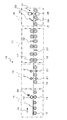
本発明の第1の実施の形態に係る基板乾燥装置と、この基板乾燥装置を使用する基板乾燥工程を含む基板処理の各工程を図1に示す。図1に示す基板処理工程10は、搬送ローラ12に載置されて搬送される基板11をブラシ13によりその表面を洗浄するブラシ洗浄工程15、ブラシ洗浄された基板11の表面にリンス液を供給するリンス工程16、リンス処理された基板11の表面を高圧液体の噴射により洗浄する高圧液体洗浄工程17、高圧液体の噴射により洗浄された基板11を乾燥させる基板乾燥工程18を有する。
FIG. 1 shows each step of substrate processing including a substrate drying apparatus according to the first embodiment of the present invention and a substrate drying process using the substrate drying apparatus. A
ブラシ洗浄工程15は、下面を搬送ローラ12に載置されて搬送される基板11の表面(上下両面)に、上下の回転ブラシ13、13を当接させて洗浄する工程である。このとき、基板上面側に当接する回転ブラシ13には、洗浄液供給装置20により洗浄液が供給される。
The
ブラシ洗浄工程15での洗浄後に基板11を処理するリンス工程16は、リンス液供給装置21から基板11の表面にリンス液を供給して、基板11に付着した洗浄用の処理液、エッチング液等をリンス処理する工程である。
A
リンス工程16の後に設けた高圧液体洗浄工程17は、高圧ツール22により高圧の液体(水、薬液等)を基板11の表面に噴射して洗浄を行う工程である。
The high-pressure
そして、高圧液体洗浄工程17で洗浄された基板11は、基板乾燥工程18に搬送される。基板乾燥工程18は、搬送中の基板11の表面に気体を噴射して基板11上の液滴を除去する工程である。
Then, the
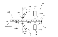
ここで、図2A及び図2Bを用いて、乾燥工程18の構成を説明する。
図1、図2A及び図2Bに示すように、基板乾燥工程18で使用される、本実施形態に係る基板乾燥装置31は、搬送ローラ12に載置されて搬送される基板11の両面(上面、下面)に向けてそれぞれ気体を噴射する一対のエアーナイフ33、34と、エアーナイフ33、34が配置された位置よりも基板11の搬送方向(矢印14の示す方向)の下流側に、基板11の両面(上面、下面)に向けてそれぞれ気体を噴射する気体噴射手段である一対のエアーブローノズル35、36と、を有する。基板乾燥装置31に搬送される基板11の一部には、基板11の上面と下面とを貫通する孔部38が形成されている。
Here, the structure of the
As shown in FIG. 1, FIG. 2A and FIG. 2B, the
エアーナイフ33、34は、先細り形状の先端に気体噴出口であるスリット33a、34aが形成された気体噴射装置で、このスリット33a、34aから高圧のカーテン状(層状)の気体を基板11に噴射して、基板11上の液滴を吹き飛ばす機能を有する。エアーナイフ33、34はそれぞれ高圧気体供給源(図示せず)と配管(図示せず)により接続されている。
The
基板乾燥装置31の概略側面図である図2Aに示すように、エアーナイフ33は、基板11の上面側に設けられ、スリット33aを下側に向けて、基板11の上面に対する垂直方向より基板11の搬送方向(矢印14の示す方向)下流側に傾斜(傾斜角A度)して配置されている。傾斜した位置に配置するのは、傾斜した方向から気体を吹き出すことで、液滴を後方に押しやり、基板上から吹き飛ばすためである。
As shown in FIG. 2A, which is a schematic side view of the
エアーナイフ34は、基板11の下面側に設けられ、スリット34aを上側に向けて、基板11の下面に対する垂直方向より基板11の搬送方向(矢印14の示す方向)下流側に傾斜(傾斜角度A度)した位置に配置されている。このように、基板11の表面(上面、下面)から液滴を排除するために、エアーナイフ33、34が基板11の上面側、下面側にそれぞれ配置されている。
The
エアーナイフ33、34は、スリット33a、33bから噴射される高圧のカーテン状(層状)の気体が基板11の幅方向(基板11の搬送方向と直交する方向)全体を覆うように、基板11の幅方向に延び、少なくとも基板11の幅方向の寸法よりも長くなっている。
The
エアーブローノズル35、36は、先端に複数のノズル35a、36aが形成された気体噴射装置で、複数のノズル35a、36aから高圧気体を噴射して液滴を直接吹き飛ばす機能を有する。本実施の形態において、エアーブローノズル35、36は、搬送される基板11を挟んで互いに上下に対向配置され、図2Bに示すように、基板11の搬送方向(矢印14の示す方向)に沿ってノズル35a、36aが2列設けられる。各列は、基板11の搬送方向と直交する方向(基板11の幅方向)に延びる4個のノズルからなる。従って、各エアーブローノズル35、36は8個のノズルを有していて、搬送ローラ12によって搬送される基板に形成される孔部38を少なくとも覆う領域(孔部38及びその周辺領域)に対し、高圧気体を噴射する。なお、エアーノズル35、36は、エアーナイフ33、34と同様に、それぞれ高圧気体供給源(図示せず)と配管(図示せず)により接続されている。
The
図2Aに示すように、エアーブローノズル35は、基板11の上面側で、ノズル35aの先端を基板11の上面側に向けて(下向きにして)、垂直方向に配置されており、ノズル35aから基板11の上面に垂直に気体が噴射されるように設定されている。また図2Bに示すように、エアーブローノズル35は、基板11に形成された孔部38の移動経路に対向するように配置される。
As shown in FIG. 2A, the
また、図2Aに示すように、エアーブローノズル36は、基板11の下面側で、ノズル36aの先端を基板11の下面側に向けて(上向きにして)、垂直方向に配置されており、ノズル36aから基板11の下面に垂直に気体が噴射されるように設定されている。また、上記したエアーブローノズル35と同様に、基板11に形成された孔部38の移動経路に対向するように配置される。
As shown in FIG. 2A, the
次に、本実施形態に係る基板乾燥装置31の動作について、図1、図2A及び図2Bを参照して説明する。
Next, the operation of the
高圧液体の噴射により洗浄する高圧液体洗浄工程17で洗浄された基板11は、搬送ローラ12に載置されて、基板乾燥工程18に搬送される。基板乾燥工程18では、基板乾燥装置31により、搬送ローラ12により搬送される基板11に対して、エアーナイフ33、34と、エアーブローノズル35、36により気体を噴射し、基板11の両面(上面、下面)に付着した液滴を吹き飛ばして、基板11を乾燥させる。具体的な内容を以下に説明する。
The
搬送ローラ12に載置されて搬送される基板11の上面には、エアーナイフ33のスリット33aより、搬送方向から吹き付ける気体が傾斜した向きで当たり、基板11上面の液滴が搬送方向上流側に押しやられて、吹き飛ばされる。また、上記同様に、搬送ローラ12に載置されて搬送される基板11の下面には、エアーナイフ34のスリット34aより、搬送方向から吹き付ける気体が傾斜した向きで当たり、基板11下面の液滴が搬送方向上流側に押しやられて、吹き飛ばされる。
The gas blown from the transport direction is inclined from the
このように、基板11の両面(上面、下面)に付着した液滴は、上記したようにエアーナイフ33、34のスリット33a、34aから噴射される気体により、両面(上面、下面)の搬送方向上流側に押しやられ、吹き飛ばされて除去される。しかしながら、エアーナイフ33、34のスリット33a、34aから噴射される気体は、上述したように両面(上面、下面)に対して傾斜した方向から吹き付けるため、基板11に形成された貫通穴である孔部38の内側には、液滴を吹き飛ばすだけの十分な量の気体が吹き付けられない。さらに、基板11の搬送方向14の下流側表面に付着した液滴が、エアーナイフ33、34から噴射される気体によって吹き飛ばされ、孔部38に入り込んでしまう。そのため、エアーナイフ33、34による気体の噴射後に、孔部38の内側に液滴が残留する場合も生じることがある。
As described above, the droplets adhering to both surfaces (upper surface and lower surface) of the
このとき、エアーナイフ33、34による気体の噴射を受けた基板11は、エアーナイフ33、34よりも基板11の搬送方向下流側に設けたエアーブローノズル35、36による気体の噴射をその両面(上面、下面)に垂直方向からそれぞれ受ける。これにより、基板11上の孔部38の内側にもエアーブローノズル35、36から噴射された気体が十分に入り込むので、孔部38に残留した液滴は吹き飛ばされ、孔部38から除去されることになる。
At this time, the
このように、基板11の両面(上面、下面)の表面上に付着した液滴をエアーナイフ33、34による表面に対して傾斜した噴射気体により効果的に除去することができると共に、エアーナイフ33、34により除去が十分に行えない孔部38の内側に付着した液滴は、エアーブローノズル35、36の複数のノズル35a、36aから垂直に噴射された気体により除去することができるので、孔部38が形成された基板11の乾燥を十分に行うことができる。
As described above, the droplets adhering to the surfaces of the both surfaces (upper surface and lower surface) of the
上記したように、本実施形態では、エアーブローノズル35、36からの気体を基板11に対して垂直方向から噴射したが、基板11の厚さ、孔部38の径サイズにより、傾斜角度を設ける方が孔部38の内側の液滴を吹き飛ばすのに効果的な場合があるときは、エアーブローノズル35、36からの噴射気体を垂直方向から傾斜させるべく、エアーブーノズル35、36を垂直方向から所定角度傾けるように設定位置を調整しても良い。
As described above, in the present embodiment, the gas from the
以上述べた実施態様によれば、エアーナイフ33、34が配置された位置よりも基板11の搬送方向下流側に基板に向けて気体を噴射するエアーブローノズル35、36を有し、エアーナイフ33、34とは異なる角度で気体を基板に噴射するので、エアーナイフ33,34により除去できない液滴に気体を噴射して除去することができる。
According to the embodiment described above, the
また、基板乾燥工程18において、エアーブローノズル35、36は、基板11の面に対して垂直方向から気体を噴射する構成であるので、エアーナイフ33、34による気体の噴射が及ばない部分に対しても、気体の噴射が及び、基板11の液滴除去の向上を図ることができる。
In the
次に、第1の実施形態の変形例について図3を参照して説明する。図3に示すように、本変形例の基板乾燥装置32では、第1の実施形態と同様の機構を有するエアーナイフ33(34)が、さらに基板11の搬送方向(矢印14の示す方向)と直交する方向に対して、エアーナイフ33(34)の一端を中心に傾斜(傾斜角B度)して配置されている(図示されないエアーナイフ34も同様)。なお、エアーナイフ33(34)の上記配置以外は第1の実施形態と同様の内容である。
Next, a modification of the first embodiment will be described with reference to FIG. As shown in FIG. 3, in the
上記エアーナイフ33(34)の両端のうち、上記の例の一端とは別の他端を中心として傾斜させることも選択できるが、基板11上の液滴を効果的に排除するためには、基板11の孔部38に近い側を上記の一端を中心に傾斜させることが好ましい。このとき、図3に示すように、エアーナイフ33(34)は基板11の孔部38寄りの一端を中心に基板11の搬送方向下流側に傾斜した配置となるので、エアーナイフ33の下を通過した基板11の液滴は、基板の隅部(基板11の幅方向で孔部38と反対側)に集められて吹き飛ばされる。
Of the two ends of the air knife 33 (34), it is possible to select to incline around the other end different from the one end of the above example, but in order to effectively eliminate the droplets on the
本変形例では、エアーナイフ33、34を平面上においても傾斜した向きに配置するので、エアーナイフ33、34による基板11上の液滴を隅部に寄せ集めて排除できるので、エアーブローノズル35、36と合わせた基板乾燥装置32による基板11の乾燥効果が向上する。
In this modification, since the
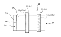
次に、本発明に係る第2の実施形態について、図4A及び図4Bを参照して説明する。なお、第1の実施形態と相違する点を中心に説明し、第1の実施形態と同一形状で同一の機能を有する構成要素については、同一名称、同一符号を付して説明する。 Next, a second embodiment according to the present invention will be described with reference to FIGS. 4A and 4B. In addition, it demonstrates centering on a different point from 1st Embodiment, and attaches | subjects and demonstrates the same name and the same code | symbol about the component which has the same function as 1st Embodiment.
本実施形態の基板乾燥装置50は、エアーブローノズル55、56が基板51の幅方向全体に気体を噴射できるように幅方向の長さが基板の長さよりも長くなるように設定されていることが(図4B参照)、第1の実施形態と相違する点である。上記以外の点は第1の実施形態と同様の構成である。
The
本実施形態では、基板乾燥工程18に搬送される基板51は、基板51aと51bが積層された積層基板であり、基板51aと基板51bとで段差53が形成されている。この段差53の基板11の幅方向(基板の搬送方向と直交する方向)に伸びる角部54は、エアーナイフ33、34により気体が十分に噴射されない範囲であり、さらにエアーナイフ33により上側の基板51aの表面上から集められた液滴が溜まり易く、エアーナイフ33、34による液滴の除去が十分に行えない範囲である。
In the present embodiment, the
基板51に形成される段差53は、基板51の幅方向(搬送方向と直交する方法)全体に形成されるので、エアーブローノズル55、56の先端部に設けられるノズル55a、56aは、基板51の搬送方向(矢印14の示す方向)に2列に配置され、基板51の搬送方向と直交する方向(基板51の幅方向)に亘って所定間隔で配置される。基板51の幅方向全体にノズル55a、56aから気体が噴射されるように、ノズルの数を適宜設定、配置する。
Since the
次に、本実施形態の動作について説明する。高圧液体の噴射により洗浄する高圧液体洗浄工程17で洗浄された基板51は、搬送ローラ12に載置されて、基板乾燥工程18に搬送される。基板乾燥工程18では、基板乾燥装置50により、搬送ローラ12により搬送される基板11に対して、エアーナイフ33、34と、エアーブローノズル55、56により気体を噴射し、基板11の両面(上面、下面)に付着した液滴を吹き飛ばして、基板11を乾燥させる。具体的な内容を以下に説明する。
Next, the operation of this embodiment will be described. The
搬送ローラ12に載置されて搬送される基板51の上側基板51aの上面には、エアーナイフ33のスリット33aより、基板の搬送方向下流側から吹き付ける気体が傾斜した向きで当たり、基板51aの上面の液滴が基板の搬送方向上流側に吹き飛ばされる。しかし、段差53の角部54には、エアーナイフ33のスリット33aからの気体が直接には吹き付けられ難く、結果として角部54に液滴が残留し易い状態となる。一方、下側の基板51bの下面は平坦であることから、エアーナイフ34により噴射される気体により、液滴が十分に吹き飛ばされ、除去される。したがって、基板51は、エアーナイフ33、34による気体の噴射後に、段差53の角部54に液滴が残留する可能性が高いことになる。
The upper surface of the
このとき、エアーナイフ33、34による気体の噴射を受けた基板51は、エアーナイフ33、34よりも基板11の搬送方向下流側に設けたエアーブローノズル55,56による気体の噴射をその両面(上面、下面)に垂直方向からそれぞれ受けるので、基板51上の段差53の角部にも、噴射された気体が十分に入り込み、段差53に残留した液滴は吹き飛ばされ、段差53から液滴が除去されることになる。なお、エアーブローノズル55を単独で使用しても段差53の角部から液滴が除去されるが、エアーブローノズル55の単独使用では、下側の基板51bの下面に液滴が回り込み、液滴の残留が生じてしまう可能性があるので、基板51全体の乾燥を十分に行うには、エアーブローノズル55、56を上下位置の一対で使用することが好ましい。
At this time, the
このように、2枚の基板51a、51bの積層による段差53を有する積層の基板51について、基板51の両面の表面上に付着した液滴をエアーナイフ33、34による噴射気体により効果的に除去することができると共に、エアーナイフ33、34により除去が十分に行えない、段差53の角部54に付着した液滴ついては、エアーブローノズル55、56の複数のノズル55a、56aから垂直に噴射された気体により除去することができるので、段差53が形成された基板51の乾燥を十分に行うことができる。
As described above, with respect to the
上記したように、本実施形態では、エアーブローノズル55、56から基板51に対して垂直方向から気体を噴射したが、基板51の厚さ、段差53の形状等により、傾斜角度を少し設ける方が段差53の角部54の液滴を吹き飛ばすのに効果的な場合があるときは、エアーブローノズル55、56からの噴射気体を垂直方向から傾斜させるべく、エアーブローノズル55、56を垂直方向から所定角度傾けるように設定位置を調整する。
As described above, in this embodiment, gas is injected from the
以上述べた実施態様によれば、例えばエアーナイフ33、34による気体の噴射後も残留する積層基板51に形成された段差53の角部54の液滴を効率良く除去することができる。
According to the embodiment described above, for example, it is possible to efficiently remove the droplets at the
次に、第2の実施形態の変形例について図5を参照して説明する。図5に示すように、本変形例の基板乾燥装置61では、第2の実施形態に示すエアーナイフ33(34)が、さらに基板11の搬送方向(矢印14の示す方向)と直交する方向に対して、エアーナイフ33(34)の一端を中心に傾斜(傾斜角B度)した位置に配置されている(図示されないエアーナイフ34も同様)。なお、エアーナイフ33(34)の上記配置以外は第2の実施形態と同様の内容である。
Next, a modification of the second embodiment will be described with reference to FIG. As shown in FIG. 5, in the
図5に示すように、エアーナイフ33(34)はその一端を中心に基板11の搬送方向下流側に傾斜した配置となっているので、エアーナイフ33の下を通過した基板11の液滴は、基板の隅部(紙面左上)に集められて吹き飛ばされる。
As shown in FIG. 5, since the air knife 33 (34) is inclined to the downstream side in the transport direction of the
本変形例では、エアーナイフ33、34を平面上においても傾斜した向きに配置するので、エアーナイフ33、34により基板11上の液滴を寄せ集めて排除できるので、エアーブローノズル55、56と合わせた基板乾燥装置61による基板11の乾燥効果が向上する。
In this modification, since the
なお、上記実施の形態においては、エアーブローノズルを上下に対向配置する例を挙げて説明したが、これに限らず、上下のいずれかのエアーブローノズルを搬送方向にずらして配置しても良い。 In the above-described embodiment, an example in which the air blow nozzles are vertically opposed to each other has been described. However, the present invention is not limited thereto, and any one of the upper and lower air blow nozzles may be shifted in the transport direction. .
11 基板
12 搬送ローラ
14 矢印(基板搬送方向を示す)
33、34 エアーナイフ
33a、34b スリット
35、36 エアーブローノズル
35a、35b ノズル
38 孔部
11
33, 34
Claims (4)
前記エアーナイフが配置された位置よりも前記基板の搬送方向下流側に、前記基板の少なくとも一方の面に向けて気体を噴射する気体噴射手段を有し、
前記気体噴射手段は、前記エアーナイフから噴射される前記気体が前記基板の面となす角度とは異なる角度で気体を前記基板の前記孔部に向けて噴射するとともに、
前記エアーナイフは、平面視で、搬送される前記基板の前記孔部に近い側の一端を中心に前記基板の搬送方向下流側に傾斜するように設けられることを特徴とする基板乾燥装置。 Surface of the substrate to be conveyed after washing hand, the gas from the slits of an air knife, a substrate drying apparatus for drying the substrate by spraying toward the upstream side of the substrate, the substrate, In the substrate drying apparatus having a hole on one side of the width direction orthogonal to the transport direction of the substrate to be transported ,
Gas injection means for injecting gas toward at least one surface of the substrate on the downstream side in the transport direction of the substrate from the position where the air knife is disposed,
The gas jetting unit jets the gas toward the hole of the substrate at an angle different from an angle formed by the gas jetted from the air knife with the surface of the substrate ,
The substrate drying apparatus , wherein the air knife is provided so as to incline toward the downstream side in the transport direction of the substrate around one end of the substrate being transported near the hole portion in plan view .
Priority Applications (1)
| Application Number | Priority Date | Filing Date | Title |
|---|---|---|---|
| JP2014070942A JP6336801B2 (en) | 2014-03-31 | 2014-03-31 | Substrate dryer |
Applications Claiming Priority (1)
| Application Number | Priority Date | Filing Date | Title |
|---|---|---|---|
| JP2014070942A JP6336801B2 (en) | 2014-03-31 | 2014-03-31 | Substrate dryer |
Related Child Applications (2)
| Application Number | Title | Priority Date | Filing Date |
|---|---|---|---|
| JP2015072055A Division JP2015198254A (en) | 2015-03-31 | 2015-03-31 | substrate processing apparatus |
| JP2018031759A Division JP6580177B2 (en) | 2018-02-26 | 2018-02-26 | Substrate dryer |
Publications (3)
| Publication Number | Publication Date |
|---|---|
| JP2015192141A JP2015192141A (en) | 2015-11-02 |
| JP2015192141A5 JP2015192141A5 (en) | 2017-03-09 |
| JP6336801B2 true JP6336801B2 (en) | 2018-06-06 |
Family
ID=54426378
Family Applications (1)
| Application Number | Title | Priority Date | Filing Date |
|---|---|---|---|
| JP2014070942A Active JP6336801B2 (en) | 2014-03-31 | 2014-03-31 | Substrate dryer |
Country Status (1)
| Country | Link |
|---|---|
| JP (1) | JP6336801B2 (en) |
Cited By (5)
| Publication number | Priority date | Publication date | Assignee | Title |
|---|---|---|---|---|
| CN108499955A (en) * | 2018-04-27 | 2018-09-07 | 江山海维科技有限公司 | A kind of medicinal cleaning device of medium-height grass based on cleaning showers technology |
| CN109396080A (en) * | 2018-12-24 | 2019-03-01 | 东莞市启力致尚技术研发有限公司 | A kind of Furniture panel dry dust removal device |
| CN111141129A (en) * | 2019-12-28 | 2020-05-12 | 天长市正牧铝业科技有限公司 | Quick drying device of club |
| CN112222079A (en) * | 2020-09-24 | 2021-01-15 | 合肥维信诺科技有限公司 | Cleaning and drying system and cleaning and drying method |
| CN112742798A (en) * | 2020-12-30 | 2021-05-04 | 泰州市博泰电子有限公司 | Circuit board cleaning device |
Families Citing this family (12)
| Publication number | Priority date | Publication date | Assignee | Title |
|---|---|---|---|---|
| CN105605909B (en) * | 2016-01-15 | 2018-01-30 | 武汉华星光电技术有限公司 | Substrate-cleaning method |
| JP2019027620A (en) * | 2017-07-26 | 2019-02-21 | 春日電機株式会社 | Water removal or dust removal machine |
| CN108339769A (en) * | 2018-01-16 | 2018-07-31 | 滁州佳宏光电有限公司 | A kind of light guide plate cleaner and its application method |
| CN108655046A (en) * | 2018-06-25 | 2018-10-16 | 东莞市赛诺办公设备科技有限公司 | A kind of charging roller iron axis washes axis machine automatically |
| CN110976388A (en) * | 2019-12-27 | 2020-04-10 | 天津彗途环保科技有限公司 | High-pressure cleaning machine with double-layer cleaning structure |
| CN111151484A (en) * | 2020-01-19 | 2020-05-15 | 富士智能机电(珠海)有限公司 | Brush-grinding type automatic cleaning device |
| JP7356368B2 (en) | 2020-02-10 | 2023-10-04 | 株式会社荏原製作所 | Substrate drying equipment |
| CN112139107B (en) * | 2020-07-30 | 2023-10-31 | 福涞堡造纸技术(上海)有限公司 | Silk screen washs drying device |
| CN112207077A (en) * | 2020-09-22 | 2021-01-12 | 江西城桥复合材料有限公司 | Drying and cleaning device for copper plate |
| CN112354931A (en) * | 2020-10-16 | 2021-02-12 | 江苏东科复合材料有限公司 | Carbon fiber is washing and drying device for bonnet processing |
| CN112207070A (en) * | 2020-11-03 | 2021-01-12 | 韩静 | Building board quick dirt cleaning device in field of constructional engineering |
| WO2022116028A1 (en) * | 2020-12-02 | 2022-06-09 | 李海霞 | Drying apparatus for special glass production |
Family Cites Families (4)
| Publication number | Priority date | Publication date | Assignee | Title |
|---|---|---|---|---|
| JP3851370B2 (en) * | 1996-03-01 | 2006-11-29 | 大日本スクリーン製造株式会社 | Substrate drainer |
| JP3918401B2 (en) * | 1999-05-31 | 2007-05-23 | 株式会社日立ハイテクノロジーズ | Substrate drying apparatus, drying method, and substrate manufacturing method |
| JP3765568B2 (en) * | 2002-04-12 | 2006-04-12 | 株式会社都ローラー工業 | Substrate moisture removal method and moisture removal apparatus |
| JP2005147621A (en) * | 2003-11-19 | 2005-06-09 | Tokyo Kakoki Kk | Drier for substrate material |
-
2014
- 2014-03-31 JP JP2014070942A patent/JP6336801B2/en active Active
Cited By (7)
| Publication number | Priority date | Publication date | Assignee | Title |
|---|---|---|---|---|
| CN108499955A (en) * | 2018-04-27 | 2018-09-07 | 江山海维科技有限公司 | A kind of medicinal cleaning device of medium-height grass based on cleaning showers technology |
| CN109396080A (en) * | 2018-12-24 | 2019-03-01 | 东莞市启力致尚技术研发有限公司 | A kind of Furniture panel dry dust removal device |
| CN109396080B (en) * | 2018-12-24 | 2021-07-13 | 上海特雷通智能家居有限公司 | Dry dust collector of furniture board |
| CN111141129A (en) * | 2019-12-28 | 2020-05-12 | 天长市正牧铝业科技有限公司 | Quick drying device of club |
| CN112222079A (en) * | 2020-09-24 | 2021-01-15 | 合肥维信诺科技有限公司 | Cleaning and drying system and cleaning and drying method |
| CN112222079B (en) * | 2020-09-24 | 2022-04-12 | 合肥维信诺科技有限公司 | Cleaning and drying system and cleaning and drying method |
| CN112742798A (en) * | 2020-12-30 | 2021-05-04 | 泰州市博泰电子有限公司 | Circuit board cleaning device |
Also Published As
| Publication number | Publication date |
|---|---|
| JP2015192141A (en) | 2015-11-02 |
Similar Documents
| Publication | Publication Date | Title |
|---|---|---|
| JP6336801B2 (en) | Substrate dryer | |
| JP6580177B2 (en) | Substrate dryer | |
| US7951244B2 (en) | Liquid cleaning apparatus for cleaning printed circuit boards | |
| TWI457266B (en) | And a substrate processing device having a non-contact floating conveyance function | |
| JP2015192141A5 (en) | ||
| JP2013173231A (en) | Method and device for cleaning nozzle plate | |
| TW201713419A (en) | Dust-removing nozzle and dust-removing apparatus | |
| TWI593470B (en) | Substrate processing apparatus, substrate processing method, substrate manufacturing apparatus, and substrate manufacturing method | |
| TWI436417B (en) | Substrate cleaning apparatus and method | |
| JP2007141933A (en) | Substrate drying apparatus and substrate processing method | |
| JP2017154111A (en) | Substrate treatment apparatus and substrate treatment method | |
| JP2015198254A (en) | substrate processing apparatus | |
| KR101499681B1 (en) | Chamber structure of substrate cleaning apparatus | |
| JP6060140B2 (en) | Dry fingerprint cleaning device | |
| JP2009165968A (en) | Cleaning method and cleaning apparatus for belt-like cleaning object | |
| WO2003071594A1 (en) | Carrier type substrate processing device | |
| CN110290699B (en) | Apparatus and method for washing shell eggs | |
| JP2007317802A (en) | Apparatus and method of dry-processing substrate | |
| KR100684048B1 (en) | Apparatus for jetting fluid | |
| JP2014038914A (en) | Drying device and drying method for substrate | |
| JP2014168896A (en) | Cleaning device of liquid droplet discharge head | |
| JP2014038915A (en) | Drying device and drying method for substrate | |
| JP5083912B2 (en) | Wiring board cleaning method | |
| JP2005169356A (en) | Air knife drying device | |
| JP6260187B2 (en) | Box turning device |
Legal Events
| Date | Code | Title | Description |
|---|---|---|---|
| A521 | Request for written amendment filed |
Free format text: JAPANESE INTERMEDIATE CODE: A523 Effective date: 20170201 |
|
| A621 | Written request for application examination |
Free format text: JAPANESE INTERMEDIATE CODE: A621 Effective date: 20170201 |
|
| A977 | Report on retrieval |
Free format text: JAPANESE INTERMEDIATE CODE: A971007 Effective date: 20171218 |
|
| A131 | Notification of reasons for refusal |
Free format text: JAPANESE INTERMEDIATE CODE: A131 Effective date: 20171226 |
|
| A521 | Request for written amendment filed |
Free format text: JAPANESE INTERMEDIATE CODE: A523 Effective date: 20180226 |
|
| TRDD | Decision of grant or rejection written | ||
| A01 | Written decision to grant a patent or to grant a registration (utility model) |
Free format text: JAPANESE INTERMEDIATE CODE: A01 Effective date: 20180424 |
|
| A61 | First payment of annual fees (during grant procedure) |
Free format text: JAPANESE INTERMEDIATE CODE: A61 Effective date: 20180507 |
|
| R150 | Certificate of patent or registration of utility model |
Ref document number: 6336801 Country of ref document: JP Free format text: JAPANESE INTERMEDIATE CODE: R150 |