JP6335576B2 - Digital linearization in weighing cells - Google Patents
Digital linearization in weighing cells Download PDFInfo
- Publication number
- JP6335576B2 JP6335576B2 JP2014065641A JP2014065641A JP6335576B2 JP 6335576 B2 JP6335576 B2 JP 6335576B2 JP 2014065641 A JP2014065641 A JP 2014065641A JP 2014065641 A JP2014065641 A JP 2014065641A JP 6335576 B2 JP6335576 B2 JP 6335576B2
- Authority
- JP
- Japan
- Prior art keywords
- coil
- force
- weight
- displacement
- load
- Prior art date
- Legal status (The legal status is an assumption and is not a legal conclusion. Google has not performed a legal analysis and makes no representation as to the accuracy of the status listed.)
- Active
Links
Images


Classifications
-
- G—PHYSICS
- G01—MEASURING; TESTING
- G01G—WEIGHING
- G01G7/00—Weighing apparatus wherein the balancing is effected by magnetic, electromagnetic, or electrostatic action, or by means not provided for in the preceding groups
- G01G7/02—Weighing apparatus wherein the balancing is effected by magnetic, electromagnetic, or electrostatic action, or by means not provided for in the preceding groups by electromagnetic action
-
- G—PHYSICS
- G01—MEASURING; TESTING
- G01G—WEIGHING
- G01G3/00—Weighing apparatus characterised by the use of elastically-deformable members, e.g. spring balances
- G01G3/12—Weighing apparatus characterised by the use of elastically-deformable members, e.g. spring balances wherein the weighing element is in the form of a solid body stressed by pressure or tension during weighing
- G01G3/14—Weighing apparatus characterised by the use of elastically-deformable members, e.g. spring balances wherein the weighing element is in the form of a solid body stressed by pressure or tension during weighing measuring variations of electrical resistance
- G01G3/1414—Arrangements for correcting or for compensating for unwanted effects
-
- G—PHYSICS
- G01—MEASURING; TESTING
- G01G—WEIGHING
- G01G7/00—Weighing apparatus wherein the balancing is effected by magnetic, electromagnetic, or electrostatic action, or by means not provided for in the preceding groups
- G01G7/02—Weighing apparatus wherein the balancing is effected by magnetic, electromagnetic, or electrostatic action, or by means not provided for in the preceding groups by electromagnetic action
- G01G7/04—Weighing apparatus wherein the balancing is effected by magnetic, electromagnetic, or electrostatic action, or by means not provided for in the preceding groups by electromagnetic action with means for regulating the current to solenoids
Description
本発明は、力測定デバイスによる重量力を判定する方法に関する。 The present invention relates to a method for determining weight force by a force measuring device.
電磁力復元またはEMFRとしても知られる電磁力補償の原理により動作するタイプの秤量セルなどの力測定デバイスにおいては、秤量対象の重量力が、直接的にあるいは1つまたは複数の支点支持された力伝達梃子を介して、電気機械測定変換器に対して伝達される。この測定変換器は、秤量対象の重量力に合致する補償力を発生させ、電気信号を送り、この電気信号が、電子集計体である信号処理ユニットにより処理および表示される。 In a force measurement device such as a weighing cell of the type that operates on the principle of electromagnetic force compensation, also known as electromagnetic force restoration or EMFR, the weight force to be weighed is a force that is supported directly or by one or more fulcrums. It is transmitted to the electromechanical measurement transducer via a transmission lever. The measurement transducer generates a compensation force that matches the weight force of the object to be weighed and sends an electrical signal that is processed and displayed by a signal processing unit that is an electronic aggregate.
EMFR秤量セルは、殆どの場合、固定平行脚部と、2つの平行ガイドにより固定平行脚部に対して連結され、荷重レシーバとして機能する可動平行脚部とを有する、平行四辺形機構を備える。梃子システムを備えるEMFR秤量セルにおいては、重量力は、長さを剛体的に維持するが曲げについては可撓性を有する継手要素により、固定平行脚部上に枢支された秤竿に対して伝達される。かかる構成は、補償力を発生させる測定変換器が重量力を表す測定信号を生成することが可能となるように、印加荷重により加えられる重量力を梃子軽減によって十分な低さにすることを目的としている。最新技術によれば、高分解能秤量セルにおける各要素間の連結部は、屈曲ピボットとして設計される。屈曲ピボットは、結合される2つの要素間の回転軸を規定する。モノリシック秤量セルまたはモノブロック秤量セルとも呼ばれる、物理的連続ユニットとして構成される秤量セルにおいては、屈曲ピボットは、幅狭材料連結部分として形成され得る。 The EMFR weighing cell most often comprises a parallelogram mechanism having a fixed parallel leg and a movable parallel leg connected to the fixed parallel leg by two parallel guides and functioning as a load receiver. In an EMFR weighing cell with a lever system, the weight force is relative to a balance pivoted on a fixed parallel leg by a joint element that maintains the length rigidly but is flexible in bending. Communicated. Such a configuration is intended to reduce the weight force applied by the applied load to a sufficiently low level by lever reduction so that the measurement transducer that generates the compensation force can generate a measurement signal representing the weight force. It is said. According to the state of the art, the connection between each element in the high resolution weighing cell is designed as a bending pivot. The bending pivot defines an axis of rotation between the two elements to be joined. In weighing cells configured as physically continuous units, also called monolithic weighing cells or monoblock weighing cells, the bending pivot can be formed as a narrow material connection.
重量力が直接的にすなわち補償力の梃子軽減を伴わずに補償されるタイプのEMFR秤量セルにおいては、平行案内機構は、殆どの場合、ばね要素として、具体的には可撓性リンクまたはダイヤフラムスプリングとして構成される。直接測定システムとも呼ばれるこのタイプの秤量セルにおいては、測定変換器は、荷重の重量力を、同等規模の補償力を用いて相殺する。 In EMFR weighing cells of the type in which the weight force is compensated directly, i.e. without compensatory lever reduction, the parallel guide mechanism is almost always a spring element, in particular a flexible link or diaphragm. Configured as a spring. In this type of weighing cell, also referred to as a direct measurement system, the measurement transducer cancels the weight force of the load using a compensatory force of comparable magnitude.
最新技術のEMFR秤量セルの測定変換器は、一般的には、永久磁石の空隙内に挿入された導電コイルとして構成されるため、秤量対象の重量力は、対応する電気変数、すなわちコイル電流Iから判定され得る。重量力は、補償力に比例し、また補償力は、コイル電流Iに比例するため、コイル電流Iもまた、重量力に比例し、したがって秤量荷重物の質量に比例することになる。秤量セルが、平衡状態にある場合には、この関係は、以下の等式で表すことが可能である(温度の影響は考慮しない)。
F’=f(I)=k×I
F’:秤量対象である質量mの算出された重量力
K:伝達定数
I:コイル電流
伝達定数kは、各タイプの秤量セルごとに設計で指定され、補償力の算出を目的として処理ユニットに格納される。換言すれば、伝達定数は、秤量セルの荷重受けシステムにより決定され、測定されたコイル電流の力F’への変換を記述する。
Since the measuring transducer of state-of-the-art EMFR weighing cells is generally configured as a conductive coil inserted into the gap of a permanent magnet, the weight force to be weighed corresponds to the corresponding electrical variable, ie the coil current I Can be determined from Since the weight force is proportional to the compensation force, and the compensation force is proportional to the coil current I, the coil current I is also proportional to the weight force, and therefore proportional to the mass of the weighing load. If the weighing cell is in equilibrium, this relationship can be expressed by the following equation (without considering the effect of temperature):
F ′ = f (I) = k × I
F ′: Calculated weight force of mass m to be weighed K: Transfer constant I: Coil current The transfer constant k is specified by design for each type of weighing cell, and is applied to the processing unit for the purpose of calculating the compensation force. Stored. In other words, the transfer constant is determined by the load cell system of the weighing cell and describes the conversion of the measured coil current into a force F ′.
EMFR秤量セルにおいて通常使用されるタイプの測定変換器においては、導電コイルは、ローレンツ力、すなわちこの場合にはコイルの補償力として現れる磁場内で移動する電荷に対して作用する力の影響下において、永久磁石の空隙内を移動する。周囲の磁場の軌道に対して横軸方向に巻かれるコイルなどの電気導体内を流れる電流により、力が、この導体に対して、およびしたがって測定変換器のコイルに対して作用する。 In a measurement transducer of the type normally used in EMFR weighing cells, the conductive coil is under the influence of Lorentz force, ie a force acting on the charge moving in the magnetic field that appears in this case as the compensating force of the coil. , Move in the gap of the permanent magnet. Due to the current flowing in an electrical conductor such as a coil wound transversely to the surrounding magnetic field trajectory, a force acts on this conductor and thus on the coil of the measuring transducer.
永久磁石の磁場は、理想的には均質であるべきだが、この条件は、実際には殆どの場合において満たされない。磁場は、永久磁石に対するコイルの異なる位置ごとに幾分か変化し得る。換言すれば、所与の規模の電流に関して、コイルにより発生する補償力は、位置依存する。これは、秤量結果の算出において考慮される必要がある。秤竿が、伝達定数kを決定した均衡位置になく、若干上方または下方に位置する場合には、格納された伝達定数は、実際の伝達定数から逸脱する。秤量セルが、衝撃および振動等々にさらされると、伝達定数の逸脱は、秤量結果の高速かつ正確な判定に影響を及ぼし、ゼロ点の逸脱が生じ得る。特に動的重量選別機においては、この問題は、高い度合いで発生する。 The field of the permanent magnet should ideally be homogeneous, but this condition is not met in most cases in practice. The magnetic field can vary somewhat for different positions of the coil relative to the permanent magnet. In other words, for a given magnitude of current, the compensation force generated by the coil is position dependent. This needs to be taken into account in calculating the weighing result. If the balance is not at the equilibrium position where the transmission constant k is determined, but slightly above or below, the stored transmission constant deviates from the actual transmission constant. When the weighing cell is exposed to shocks, vibrations, etc., the deviation of the transfer constant affects the fast and accurate determination of the weighing result and zero point deviation can occur. Especially in dynamic weight sorters, this problem occurs to a high degree.
この問題を緩和するために、最新技術の力測定デバイスにおいては、補償力を表す信号に対して作用する電子フィルタが使用される。力測定デバイスの動作状態において、補償力の算出は、磁石のおよび屈曲ピボットのばね定数の温度依存性に基づき補正を加えることによって、周囲条件に対して適合化される。また、デバイスをオンに切り替えることと秤量荷重の変化とに付随する動的効果も、考慮される。さらに、時間依存性現象もまた、この補償に含まれる。荷重レシーバに対する質量の重量力の計算は、以下の関数で数学的に表すことができる。
F’=f(I、T、t)
伝達関数とも呼ばれるこの関数は、コイル電流の信号および種々の温度センサの信号を、ディスプレイ上に表示される時間依存性出力値へと変換する役割を果たす。したがって、伝達定数は、伝達関数の一部となる。コイル電流は、以下の関数に従って位置制御ユニットにより調整される。
I=f(F、z、T、t)
これは、温度効果(T)および動的効果(t)に加えて、可能である干渉パラメータ(z)をさらに考慮に入れる。
To alleviate this problem, state-of-the-art force measurement devices use electronic filters that act on the signal representing the compensation force. In the operating state of the force measuring device, the calculation of the compensation force is adapted to the ambient conditions by applying corrections based on the temperature dependence of the spring constant of the magnet and of the bending pivot. The dynamic effects associated with switching on the device and changing the weighing load are also taken into account. Furthermore, time dependent phenomena are also included in this compensation. The calculation of the mass gravimetric force on the load receiver can be expressed mathematically with the following function:
F ′ = f (I, T, t)
This function, also called the transfer function, serves to convert the coil current signal and various temperature sensor signals into time-dependent output values that are displayed on the display. Therefore, the transfer constant becomes a part of the transfer function. The coil current is adjusted by the position control unit according to the following function.
I = f (F, z, T, t)
This further takes into account possible interference parameters (z) in addition to temperature effects (T) and dynamic effects (t).
動的重量選別機は、製品がこの選別機上を移動している間に生産ライン中の製品を秤量する、これらの製品を所与の重量クラスに分類する、および/または重量クラスに応じて製品を仕分および/または除外する役割を果たす、システムである。重量選別機は、例えば
重量超過製品および重量不足製品を検査すること、
包装された商品の正味内容量に関する法的要件に準拠すること、
重量選別機により収集された重量データを使用して充填マシンの設定を調節することにより、製品廃棄を削減すること、
重量により製品を分類すること、
生産施設または生産ラインの性能を測定および記録すること、
重量に基づきピース総数を確認すること
などを含む、多様な用途において使用される。
A dynamic weight sorter weighs products in a production line while products are moving on the sorter, classifies these products into a given weight class, and / or depending on the weight class A system that serves to sort and / or exclude products. The weight sorter, for example, inspects overweight and underweight products,
Comply with the legal requirements for the net content of the packaged goods,
Reduce product disposal by adjusting the filling machine settings using the weight data collected by the weight sorter,
Classifying products by weight,
Measuring and recording the performance of production facilities or production lines;
Used in a variety of applications, including checking the total number of pieces based on weight.
重量選別機は、製品ラインの全ての製品を秤量することを目的とする。その結果、総生産量についてのデータが収集されることにより、生産されたユニット数が算出され、生産ロットが追跡可能となり、または生産統計が得られる。 The weight sorter is intended to weigh all products in the product line. As a result, by collecting data on the total production volume, the number of units produced can be calculated, the production lot can be traced, or production statistics can be obtained.
重量選別システムは、一般的には、送込みコンベヤ、秤量コンベヤ、仕分デバイスを有する送出しコンベヤ、およびユーザインターフェースを有する秤量端末から構成される。送込みコンベヤと送出しコンベヤとの間に配置される秤量コンベヤは、製品が秤量コンベヤ上を移動する際にこの製品を秤量する秤量セルによって支持される。 A weight sorting system generally consists of an infeed conveyor, a weighing conveyor, a delivery conveyor with a sorting device, and a weighing terminal with a user interface. A weighing conveyor disposed between the infeed conveyor and the delivery conveyor is supported by a weighing cell that weighs the product as it moves over the weighing conveyor.
動的重量選別機の動作において、製品は、送込みコンベヤベルトから秤量コンベヤベルトまで移動し、その移動中に秤量され、次いで、送出しコンベヤを経由して進む。秤量結果を判定するために使用し得る時間は、秤量コンベヤの長さおよび輸送速度により決定される。秤量セルにより支持される秤量コンベヤベルトは、製品が送込みコンベヤから到着した際にこの製品の重量を受け、製品が送出しコンベヤへと移ると、この重量から再び解放される。したがって、製品の連続秤量においては、秤量セルは、荷重および荷重解除を交互に受ける。この交互の荷重は、コンベヤベルトを動揺させ、この動揺は、製品がコンベヤベルト上に完全に載置される期間が非常に短くなることにより、秤量結果に対して顕著な影響をもたらす。 In operation of the dynamic weight sorter, the product moves from the infeed conveyor belt to the weighing conveyor belt, is weighed during the movement, and then proceeds through the delivery conveyor. The time that can be used to determine the weighing result is determined by the length of the weighing conveyor and the transport speed. The weighing conveyor belt supported by the weighing cell receives the weight of the product as it arrives from the infeed conveyor and is released again from this weight as the product moves to the delivery conveyor. Thus, in continuous weighing of products, the weighing cell is alternately subjected to loading and unloading. This alternating load causes the conveyor belt to sway, and this sway has a significant effect on the weighing result due to the very short period during which the product is completely placed on the conveyor belt.
動揺または振動の存在下において秤量結果をより迅速に得るために、EP0430695A2においては、2つの秤量セルを同時に使用するコンセプトが提案されている。第1の秤量セルは、秤量荷重を受け、発生した補償力に基づき対応する信号を処理ユニットに送出する。第2の秤量セルは、基準重量による同一の動揺または振動下における第1の秤量セルの挙動を反映した信号を、処理ユニットへと送出する機能を有する。処理ユニットは、第1の秤量セルの信号から第2の秤量セルの信号を減算し、このようにして第1の秤量セルの信号における動揺および振動を消去することにより、秤量結果が生成される。このコンセプトは、2つの秤量セルが各秤量ステーションごとに必要となるために、製造コストが大幅に増加するという欠点を有する。また、2つの荷重セルが厳密に均等な慣性量を有さない場合があり、したがって動揺および振動に対する応答が2つの秤量セルで異なる場合があるため、秤量結果が完全には補正され得ない点に留意する必要もある。 In order to obtain the weighing result more quickly in the presence of shaking or vibration, EP0430695A2 proposes the concept of using two weighing cells simultaneously. The first weighing cell receives a weighing load and sends a corresponding signal to the processing unit based on the generated compensation force. The second weighing cell has a function of sending a signal reflecting the behavior of the first weighing cell under the same fluctuation or vibration based on the reference weight to the processing unit. The processing unit subtracts the signal of the second weighing cell from the signal of the first weighing cell and thus eliminates the shaking and vibration in the signal of the first weighing cell, thereby producing a weighing result. . This concept has the disadvantage that production costs are greatly increased since two weighing cells are required for each weighing station. Also, the two load cells may not have strictly equal inertial amounts, and therefore the response to shaking and vibration may be different between the two weighing cells, so that the weighing result cannot be completely corrected. It is also necessary to pay attention to.
また、電磁力補償の原理により動作する力測定セルをその大半が有する微量天秤においては、ゼロ点の逸脱が見受けられ得る。これらの秤は、0.001ミリグラムの測定分解能で、すなわち1000万分の1の精度で、10グラムの秤量荷重を測定することが可能である。したがって、例えば建築物内のエレベータなどの環境由来の最小振動でさえもが、ゼロ点の逸脱を生じさせるのに十分なものとなる。ゼロ点の逸脱は、ユーザに対しては、示される表示値の増加として現れ、この増加は、擾乱の整定後に徐々にのみ正常に戻る。長期間にわたる測定では、この種の事象は、測定全体を深刻な使用不能に陥らせる恐れがある。 Further, in a microbalance having a majority of force measuring cells that operate according to the principle of electromagnetic force compensation, a deviation from the zero point can be observed. These scales are capable of measuring 10 grams of weighing load with a measurement resolution of 0.001 milligrams, that is, with a precision of 1 / 10,000,000. Thus, even minimal vibrations from the environment, such as elevators in buildings, are sufficient to cause a zero point deviation. The zero point deviation appears to the user as an increase in the displayed value shown, and this increase only gradually returns to normal after disturbance settling. In long-term measurements, this type of event can make the entire measurement seriously unusable.
動揺または振動が秤量結果に対して有する影響を低減させるための別のアプローチは、弾性減衰システムを用いて、高重量の台または支持構造体の上に秤を設置することを伴う。この方法は、微量天秤が使用される位置または秤量ステーションにおいて、好ましい。この解決策もまた、秤量ステーションを設置するための調達コストを増加させる。 Another approach to reduce the impact of shaking or vibration on the weighing result involves placing the scale on a heavy platform or support structure using an elastic damping system. This method is preferred at the location where the microbalance is used or at the weighing station. This solution also increases the procurement costs for installing the weighing station.
例えばEP0359978A3などに記載されているような、秤量結果を算出するための基礎としてコイル電流のみを使用する現行技術による解決策は、秤量結果がコイル電流から算出されるときに、秤がその整定位置に、またはより具体的には線形化された秤量結果が測定されたコイル電流に適合する位置に、到達していることが必要となるという欠点を有する。例えば動揺または振動などの擾乱が存在する場合にはその度に、力測定デバイスは、その正確な整定位置からの不安定化を被り、これが、ゼロ点の逸脱を生じさせ得る。
Current state-of-the-art solutions that use only the coil current as the basis for calculating the weighing result, for example as described in
本明細書においては、「動揺(oscillations)」という用語は、変動(fluctuations)とも呼ばれ、平均値からのシステムの状態変数の動的逸脱を指す。本コンテクストにおける「振動(vibration)」という用語は、システムの周期的な交互に生じる動きを指し、この動きは、大抵は中〜高振動数の範囲内の、かつ低振幅のものである。 As used herein, the term “oscillations”, also referred to as fluctuations, refers to the dynamic deviation of system state variables from the mean value. The term “vibration” in this context refers to the periodic alternating movement of the system, which is mostly in the mid-high frequency range and of low amplitude.
米国特許出願公開第2003/0229600A1号においては、秤量セルを備えるプラットフォームがアナログ/デジタル変換器に出力信号を送達する、対象を高速秤量するための方法が開示される。結果的に得られるデジタル出力信号は、ローパスフィルタにより処理され、プラットフォーム上の対象の重量を判定するためにマイクロプロセッサにより分析される。適切な電子フィルタによる測定されたコイル電流の平滑化は、算出されることとなる秤量結果を安定化するための手段として公知である。この場合の欠点は、この方法の速度および精度が、フィルタパラメータに依存し、殆どの場合において相互に排他的であるため、秤量結果の正確な判定にはより多くの時間が必要となる点、および対照的に、秤量結果の迅速な判定では精度がより低くなる点である。 In US 2003/0229600 A1, a method for fast weighing a subject is disclosed in which a platform with a weighing cell delivers an output signal to an analog / digital converter. The resulting digital output signal is processed by a low pass filter and analyzed by a microprocessor to determine the weight of the object on the platform. Smoothing the measured coil current with a suitable electronic filter is known as a means for stabilizing the weighing results to be calculated. The disadvantage here is that the speed and accuracy of this method depends on the filter parameters and in most cases are mutually exclusive, so that more accurate determination of the weighing result requires more time, And in contrast, a quick determination of the weighing result is less accurate.
本発明の目的は、秤量結果が迅速におよび同時に正確に判定され得る方法を提供することである。
さらに、本発明の目的は、強力な振動および/または周囲環境に由来する振動の存在下において正確な秤量結果を迅速に得ることを可能にすることである。
It is an object of the present invention to provide a method by which weighing results can be determined quickly and accurately at the same time.
Furthermore, it is an object of the present invention to make it possible to quickly obtain accurate weighing results in the presence of strong vibrations and / or vibrations originating from the surrounding environment.
本発明によれば、これらの課題は、請求項1に記載されるような、電磁力補償の原理に基づく力測定デバイスを用いて重量力を判定する方法により解決される。
印加荷重の重量を判定するこの方法は、電磁力補償の原理により動作し、磁石システム内に可動的に挿入され電流を帯びることが可能であるコイルを備える測定変換器を備える、力測定デバイスにおいて実施されるように設計される。この力測定デバイスは、荷重受け部と測定変換器のコイルまたは磁石システムとの間の力伝達機械連結部と、荷重受け部上に荷重を加えた結果として発生する、磁石システムに対する整定位置からのコイルの変位を判定する役割を果たす位置センサとをさらに備える。コイルを流れる電流は、コイルと磁石システムとの間に電磁力を発生させる機能を有し、これにより、コイルおよびコイルまたは磁石システムに対して連結された荷重受け部は、整定位置へと戻されるおよび/または整定位置に保持される。電流の規模および整定位置からのコイルの変位量が、印加荷重の重量力を判定するために使用される。
According to the invention, these problems are solved by a method for determining gravitational force using a force measuring device based on the principle of electromagnetic force compensation as claimed in
This method of determining the weight of an applied load operates in a force measurement device comprising a measurement transducer comprising a coil that operates according to the principle of electromagnetic force compensation and is movably inserted into a magnet system and can carry a current. Designed to be implemented. This force measuring device is a force transmission mechanical connection between the load receiver and the coil or magnet system of the measuring transducer, and from a settling position relative to the magnet system that occurs as a result of applying a load on the load receiver. And a position sensor for determining the displacement of the coil. The current flowing through the coil has the function of generating an electromagnetic force between the coil and the magnet system, whereby the coil and the load receiver connected to the coil or magnet system are returned to the settling position. And / or held in a settling position. The magnitude of the current and the amount of coil displacement from the settling position are used to determine the weight force of the applied load.
本発明の1つの結果として、整定位置からのコイルの変位が、追加的な入力として処理ユニットに送出されることにより、力測定デバイスは、表示値の算出において整定位置からのコイルの変位量を考慮に入れることが可能となる。これにより、例えば磁石システムの不均質性、および位置測定の、平行案内リンク装置の、具体的には屈曲ピボットまたは弾性リンクの、またはダイヤフラムスプリングの非線形性、および力測定デバイスが梃子システムを備える場合には梃子伝達比の非線形性などの非線形性を、秤量結果の算出に含むことも可能となる。 As a result of the present invention, the displacement of the coil from the settling position is sent as an additional input to the processing unit so that the force measuring device can determine the amount of coil displacement from the settling position in calculating the display value. Can be taken into account. This allows, for example, inhomogeneity of the magnet system and position measurement, of the parallel guide link device, in particular of the bending pivot or elastic link, or of the diaphragm spring, and when the force measuring device comprises an insulator system It is possible to include non-linearity such as non-linearity of the insulator transmission ratio in the calculation of the weighing result.
測定変換器は、力測定デバイス内に様々な様式で配置され得る。コイルは、可動平行脚部に対して装着されるかまたは可動平行脚部に対する連結を有し、磁石システムは、固定平行脚部に対して装着されるかまたは固定平行脚部に対する連結を有する。あるいは、コイルは、固定平行脚部に対して装着されるかまたは固定平行脚部に対する連結を有し、磁石システムは、可動平行脚部に対して装着されるかまたは可動平行脚部に対する連結を有する。いずれの場合においても、コイルおよび磁石システムは、相互に対して移動可能である。殆どの場合ではPID制御ループにより調整される、コイルを流れる電流は、いずれの場合でも、コイルと磁石システムとの間に電磁力を発生させ、これにより、コイルは、荷重が荷重受け部に加えられた場合に、磁石システムに対する整定位置へと戻る、または整定位置に保持される。磁石システムに対して可動に配置されたコイルは、1つまたは複数のコイル巻線を有することが可能である。磁石システム自体は、永久磁石または電流により励磁される電磁石であることが可能である。最も一般的な構成は、固定部に対して磁石システムを装着すること、および荷重受け部に対して直接的にまたは1つまたは複数の梃子を介してコイルを連結することである。この構成は、コイルのより低い慣性質量により、コイルが整定位置により迅速に戻ることが可能となり、整定位置により安定的に留まることが可能となるため、殆どの場合に勧められる。しかし、磁石システムが、例えばコイルに対する電流の送達を単純化するようになど、可動部上に永久磁石として配置される力測定デバイスも存在する。 The measurement transducer can be arranged in various ways within the force measurement device. The coil is attached to or has a connection to the movable parallel leg, and the magnet system is attached to or has a connection to the fixed parallel leg. Alternatively, the coil is attached to or has a connection to the fixed parallel leg, and the magnet system is attached to or has a connection to the movable parallel leg. Have. In either case, the coil and magnet system are movable relative to each other. In most cases, the current flowing through the coil, regulated by the PID control loop, in any case generates an electromagnetic force between the coil and the magnet system, which causes the coil to add a load to the load receiver. If so, it returns to the settling position for the magnet system or is held in the settling position. A coil that is movably disposed with respect to the magnet system may have one or more coil windings. The magnet system itself can be a permanent magnet or an electromagnet excited by an electric current. The most common configuration is to attach the magnet system to the fixed part and to connect the coil directly to the load receiving part or via one or more insulators. This configuration is recommended in most cases because the lower inertial mass of the coil allows the coil to return more quickly to the settling position and remain stable at the settling position. However, there are also force measurement devices where the magnet system is arranged as a permanent magnet on the moving part, for example to simplify the delivery of current to the coil.
整定位置は、システムに対して作用する全ての力が相互に平衡状態になる、磁石システムに対するコイルの位置である。また、梃子システムにおいては、これは、秤竿のゼロ位置でもある。コイルが、秤竿に対して連結されることにより、整定位置からの秤竿の逸脱は、整定位置からのコイルの逸脱と一致する。これと同じことが、コイルの代わりに磁石システムが秤竿に連結された場合にも当てはまる。力伝達機械連結部のコンテクストにおいて本明細書で使用される場合の「秤竿」という用語は、位置センサにより整定位置がモニタリングされる、単アーム梃子または両アーム梃子を指す。好ましくは、秤竿の支点軸、秤竿の重力の質量中心、継手部材に対する第1の梃子アームの連結、および測定変換器により発生される力の印加点は、共通平面内に位置する。この条件が満たされる場合には、秤量荷重が不在である秤竿は、いかなるトルクも受けず、支持ベースの非水平条件とは無関係に常に平衡状態に置かれる。また、前述の点により画定される平面は、水平無関係面(level−indifferent plane)とも呼ばれる。 The settling position is the position of the coil relative to the magnet system where all forces acting on the system are in equilibrium with each other. In the insulator system, this is also the zero position of the balance. With the coil connected to the balance, the deviation of the balance from the settling position coincides with the deviation of the coil from the settling position. The same is true if the magnet system is connected to a balance instead of a coil. The term “balance” as used herein in the context of a force transmission mechanical connection refers to a single arm or both arm insulator whose position is monitored by a position sensor. Preferably, the fulcrum shaft of the balance, the center of gravity of the balance of the balance, the connection of the first lever arm to the joint member, and the point of application of the force generated by the measuring transducer lie in a common plane. If this condition is met, the balance without the weighing load will not receive any torque and will always be in equilibrium regardless of the non-horizontal condition of the support base. The plane defined by the aforementioned points is also called a level-independent plane.
直接測定システムにおいては、測定変換器のコイルまたは磁石システムは、荷重受け部に対して直接的に連結された力伝達ロッドに対して装着されるため、印加力を軽減するための梃子は存在しない。直接測定システムにおける整定位置からのコイルのまたは磁石システムの変位は、整定位置からの力伝達ロッドの変位と同一となる。 In the direct measurement system, the coil or magnet system of the measurement transducer is mounted on a force transmission rod that is directly connected to the load receiver, so there is no insulator to reduce the applied force . The displacement of the coil or magnet system from the settling position in the direct measurement system is the same as the displacement of the force transmission rod from the settling position.
本発明のコンセプトによる方法に対する好ましい一適用例は、微量天秤におけるものである。なぜならば、本発明により、動揺および/または振動の存在下における力測定デバイスの安定性が向上するからである。 One preferred application for the method according to the inventive concept is in a microbalance. This is because the present invention improves the stability of the force measuring device in the presence of shaking and / or vibration.
また、この方法は、重量選別機に特に非常に適する。なぜならば、この場合には、重量選別機のコンベヤベルトが、秤量される製品の送込みおよび送出しにより動揺状態および/または振動状態へと励振されることが頻繁に起こるからである。 This method is also particularly suitable for weight sorters. This is because, in this case, it frequently occurs that the conveyor belt of the weight sorter is excited into a swaying and / or oscillating state by feeding and delivering the product to be weighed.
本発明は、プッシュ原理により補償力を発生させる測定変換器と、プッシュ/プル原理により動作する測定変換器とを有する、力測定デバイスに適する。違いは、補償力を発生させる様式にある。プッシュシステムは、一方向にのみ補償力を発生させ得るが、プッシュ/プルシステムは、両方向に補償力を発生させる能力を有する。 The present invention is suitable for a force measuring device having a measuring transducer that generates a compensation force according to the push principle and a measuring transducer that operates according to the push / pull principle. The difference is in the manner in which compensation is generated. A push system can generate compensation force in only one direction, but a push / pull system has the ability to generate compensation force in both directions.
本発明の一実施形態によれば、整定位置からのコイルの変位量が、位置センサにより測定および定量化され、この位置センサは、位置制御ユニットに入力信号を供給し、位置制御ユニットは、コイルおよびコイルまたは磁石システムに対して連結された荷重受け部が、コイルと磁石システムとの間の電磁力により整定位置へと戻されるように、コイルを通る電流を調整する。代替的には、整定位置からのコイルの変位量は、追加の位置センサを用いて判定することも可能である。整定位置からのコイルの変位を測定する最も単純な方法は、位置制御ユニットの位置センサの位置信号を使用することである。しかし、秤竿の位置または磁石システム内における整定位置からのコイルの変位または整定位置からの秤竿の変位に関する同一の情報を送達する追加のセンサを使用することもまた可能である。このセンサ信号は、例えば加速度センサ、速度センサ、角度測定センサ、または位置センサなどにより、プロセッサユニットに各情報を供給するために生成され得る。 According to one embodiment of the present invention, the amount of displacement of the coil from the settling position is measured and quantified by a position sensor, which provides an input signal to the position control unit, And the load receiver connected to the coil or magnet system adjusts the current through the coil so that it is returned to the settling position by the electromagnetic force between the coil and the magnet system. Alternatively, the amount of displacement of the coil from the settling position can be determined using an additional position sensor. The simplest way to measure the coil displacement from the settling position is to use the position signal of the position sensor of the position control unit. However, it is also possible to use additional sensors that deliver the same information regarding the position of the balance or the displacement of the coil from the settling position in the magnet system or the displacement of the balance from the settling position. This sensor signal may be generated to supply each information to the processor unit by, for example, an acceleration sensor, a speed sensor, an angle measurement sensor, or a position sensor.
本発明の有利な一実施形態により印加荷重の重量力を判定するために、処理ユニットに格納され、電流の規模と整定位置からのコイルの変位規模と重量力との間の相関関係を確立する、算術命令の形態の伝達手段が使用される。本明細書においては、「伝達手段」という用語は、処理ユニットに、入手可能な入力量を表示値へと変換させるための、すなわち重量力F’の値を算出させるための、数学的命令の意味において使用される。 In order to determine the gravitational force of the applied load according to an advantageous embodiment of the present invention, a correlation is established between the magnitude of the current and the displacement magnitude of the coil from the settling position and the gravitational force to determine the gravitational force of the applied load A communication means in the form of an arithmetic instruction is used. In the present specification, the term “transmission means” is a mathematical instruction for causing a processing unit to convert an available input quantity into a display value, ie for calculating the value of weight force F ′. Used in meaning.
本発明のさらに展開される実施形態によれば、伝達手段は、整定位置からのコイルの変位量と、コイル電流の規模とが、印加荷重の重量力の値に相互に関係づけられる、伝達テーブルとして格納される。さらなる可能なものとしては、少なくとも1つのパラメータを有し、少なくとも整定位置からのコイルの変位規模とコイル電流の規模とを入力量として使用する、伝達関数として伝達手段を格納することがある。 According to a further developed embodiment of the present invention, the transmission means includes a transmission table in which the amount of displacement of the coil from the settling position and the magnitude of the coil current are correlated to the value of the weight force of the applied load. Is stored as A further possibility is to store the transfer means as a transfer function having at least one parameter and using at least the displacement magnitude of the coil from the settling position and the magnitude of the coil current as input quantities.
伝達テーブルが、算出用の命令として使用される場合には、表示値は、整定位置からのコイルの変位量および電気コイル電流の規模の関数としての表示値をリストしたテーブル内に見出される。本明細書において使用される場合の「伝達関数」という用語は、少なくとも2つの入力量および少なくとも1つのパラメータを用いた数学関数を意味する。本発明のコンテクスト内においては、伝達関数の少なくとも1つのパラメータは、整定位置からのコイルの変位規模と電気コイル電流の規模との間の関係を記述する数学関数の変数として理解される。 If the transfer table is used as a calculation command, the display value is found in a table listing the display value as a function of the amount of coil displacement from the settling position and the magnitude of the electrical coil current. The term “transfer function” as used herein means a mathematical function with at least two input quantities and at least one parameter. Within the context of the present invention, at least one parameter of the transfer function is understood as a mathematical function variable describing the relationship between the magnitude of displacement of the coil from the settling position and the magnitude of the electric coil current.
本発明のさらなる一実施形態によれば、伝達関数の少なくとも1つのパラメータは、パラメータテーブルとしておよび/またはシステムの特徴曲線として格納される。やはりこの場合にも、適切なパラメータは、コイルの変位量と電気コイル電流の規模とに応じて、またはシステムグラフの場合にはシステムグラフを記述するパラメータとして、パラメータテーブルから選択される
本発明の別の有利な実施形態においては、伝達関数の少なくとも1つのパラメータは、荷重依存性である。
According to a further embodiment of the invention, at least one parameter of the transfer function is stored as a parameter table and / or as a characteristic curve of the system. Again in this case, the appropriate parameters are selected from the parameter table depending on the amount of coil displacement and the magnitude of the electric coil current, or in the case of system graphs, as parameters describing the system graph. In another advantageous embodiment, at least one parameter of the transfer function is load dependent.
本発明の有利な一実施形態によれば、伝達テーブルの値および/または伝達関数の少なくとも1つのパラメータは、コイルの変位を変更し、実質的に同時にコイルの変位に関連付けられる電気コイル電流の規模を測定することにより、および/または、電気コイル電流の規模を変更し、実質的に同時に電気コイル電流の規模に関連付けられるコイルの変位を測定することにより、および/または、振動の存在下において電気コイル電流の規模に対するコイルの変位を分析することにより、決定される。 According to an advantageous embodiment of the invention, the value of the transfer table and / or at least one parameter of the transfer function changes the displacement of the coil and the magnitude of the electrical coil current associated with the displacement of the coil substantially simultaneously. And / or changing the magnitude of the electrical coil current and measuring the displacement of the coil associated with the magnitude of the electrical coil current substantially simultaneously and / or in the presence of vibration It is determined by analyzing the displacement of the coil with respect to the magnitude of the coil current.
振動の存在下における分析により伝達テーブルの値および/または伝達関数の少なくとも1つのパラメータを判定するこのコンセプトは、重量選別機の場合に特に優先的に使用される。 This concept of determining the value of the transfer table and / or at least one parameter of the transfer function by analysis in the presence of vibration is particularly preferentially used in the case of a weight sorter.
本発明の別の態様によれば、伝達テーブルの値の決定および/または伝達関数の少なくとも1つのパラメータの決定は、荷重受け部に加えられる重量がある状態およびない状態の両方においてなされ、重量は、外部から荷重受け部に対して加えられる重量か、または機構により内部的に加えられ得る重量のいずれかであることが可能である。異なる荷重条件下において値および/または少なくとも1つのパラメータを決定することにより、重量測定型測定デバイスの全秤量範囲にわたる出力値の精度が向上する。 According to another aspect of the invention, the determination of the value of the transfer table and / or the determination of at least one parameter of the transfer function is made both with and without the weight applied to the load receiver, the weight being It can be either the weight applied to the load receiver from the outside or the weight that can be applied internally by the mechanism. By determining the value and / or at least one parameter under different loading conditions, the accuracy of the output value over the entire weighing range of the gravimetric measuring device is improved.
本発明の特に有利な一実施形態によれば、伝達手段は、各力測定デバイスに対して個別に、または同一タイプの力測定デバイスに対して汎用的に生成される。自明ではあるが、磁石システム、屈曲ピボット、位置測定、および梃子軽減比についての製造公差により、それぞれ個々のユニットが、1つの固有の力測定デバイスに対してのみ有効となる固有の値および/またはパラメータを有する。力測定デバイスの生産においてこれらの値および/またはパラメータの決定の速度を上げるために、あらかじめ決定された伝達手段の算術平均に基づく汎用伝達手段を、処理ユニット内のメモリに格納することが可能である。 According to one particularly advantageous embodiment of the invention, the transmission means are generated individually for each force measuring device or universally for the same type of force measuring device. Obviously, due to manufacturing tolerances on the magnet system, bending pivot, position measurement, and lever reduction ratio, each individual unit has a unique value and / or value that is valid for only one unique force measurement device. Has parameters. In order to speed up the determination of these values and / or parameters in the production of force measuring devices, a universal transmission means based on the arithmetic mean of the predetermined transmission means can be stored in a memory in the processing unit. is there.
電磁力補償の原理により重量力を判定するための重量測定型力測定デバイスの力測定セルであって、磁石システム内に可動的に挿入されるコイルを備える測定変換器を備え、さらに測定変換器と荷重受け部との間の力伝達機械連結部を備え、コイルまたは磁石システムのいずれかが荷重受け部に対して連結される、力測定セルは、力測定セルが、荷重受け部に対して荷重を加えることにより発生する整定位置からのコイルの変位を検出および測定することが可能な位置センサを有し、整定位置からのコイルの変位量が、重量力の判定工程において利用し得る点によって、区別される。 A force measuring cell of a gravimetric force measuring device for determining weight force according to the principle of electromagnetic force compensation, comprising a measuring transducer comprising a coil movably inserted in a magnet system, further measuring transducer Force measuring machine connection between the load receiving part and either the coil or the magnet system is connected to the load receiving part, the force measuring cell is the force measuring cell to the load receiving part It has a position sensor that can detect and measure the displacement of the coil from the settling position generated by applying a load, and the amount of displacement of the coil from the settling position can be used in the weight force determination process Are distinguished.
電磁力補償原理により動作する力測定デバイスにより重量力を判定する方法を実装するためのコンピュータプログラムにおいては、重量力の表示値が、出力として生成される。力測定デバイスは、磁石システム内に可動的に挿入され、コイルと磁石システムとの間に相互作用力を発生させる電流を帯びることが可能な、コイルを備え、それにより、コイルおよびコイルまたは磁石システムに対して連結された荷重受け部は、整定位置へと戻されるおよび/または整定位置に保持される。この力測定デバイスは、コイルと荷重受け部との間の力伝達機械連結部をさらに備え、また、荷重受け部に対して荷重を加えることにより発生する整定位置からのコイルの変位を検出することが可能なセンサを備える。コンピュータプログラムに入力する入力量は、少なくとも電気コイル電流の規模と、整定位置からのコイルの変位量とを含む。 In a computer program for implementing a method for determining weight force by a force measuring device operating according to the principle of electromagnetic force compensation, a display value of weight force is generated as output. The force measuring device comprises a coil that is movably inserted into the magnet system and can carry an electric current that generates an interaction force between the coil and the magnet system, whereby the coil and the coil or magnet system Is connected to the settling position and / or held in the settling position. The force measuring device further includes a force transmission mechanical connecting portion between the coil and the load receiving portion, and detects a displacement of the coil from a settling position generated by applying a load to the load receiving portion. Equipped with a sensor capable of The input amount input to the computer program includes at least the magnitude of the electric coil current and the displacement amount of the coil from the settling position.
コンピュータプログラムの好ましい一実施形態は、入力量として時間信号および少なくとも1つの温度信号をさらに使用する。これにより、磁石システムの磁場に対する温度効果および/または熱膨張による梃子伝達比の変化および/または屈曲ピボットの弾性復元力の変化をさらに考慮に入れることが確実に可能となる。時間信号が、オン切替え局面においてもしくは荷重の変化時に動的効果の補償を目的として、または時間依存補償を目的として、使用される。 A preferred embodiment of the computer program further uses a time signal and at least one temperature signal as input quantities. This ensures that the temperature effect on the magnetic field of the magnet system and / or the change of the lever transmission ratio due to thermal expansion and / or the change of the elastic restoring force of the bending pivot can be further taken into account. A time signal is used in the on-switching phase or for compensation of dynamic effects during load changes or for the purpose of time-dependent compensation.
コンピュータプログラムのさらなる一実施形態においては、コンピュータプログラムは、プログラムを実行しているユニットのワーキングメモリに格納され得る伝達手段を呼び出すことが可能である。 In a further embodiment of the computer program, the computer program can call a communication means that can be stored in the working memory of the unit executing the program.
コンピュータプログラムが、秤量対象を秤に運ぶための送込みコンベヤベルトと、秤量対象を秤から運び去るための送出しコンベヤベルトと、力測定デバイスに対して連結された秤量コンベヤベルトとを備える、重量選別システムにおいて使用される場合に、重量力の判定は、コンピュータプログラムにより端末において実施される。 A computer program comprising an infeed conveyor belt for carrying a weighing object to a scale, a delivery conveyor belt for carrying the weighing object off the scale, and a weighing conveyor belt connected to a force measuring device When used in a sorting system, the determination of weight force is performed at a terminal by a computer program.
以下、本発明の対象が、添付の図面に示される好ましい実施形態の例を介してさらに説明される。 In the following, the subject of the present invention will be further illustrated through examples of preferred embodiments shown in the accompanying drawings.
以下の説明において、同一の機能および同様の構成を有する特徴は、同一の参照符号によって示される。
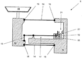
図1は、力測定デバイス1の力測定セルを側方からの断面図において概略的に示す。固定部11を介して、力測定デバイス1は、支持構造体上に取り付けられる。2つの平行ガイド14により固定部11に対して連結された荷重受け部12は、秤量荷重物が配置される秤量皿15を担持する。平行ガイド14は、屈曲ピボット16により、荷重受け部12に対しておよび固定部11に対して連結される。屈曲ピボットが、回転軸を規定するが、屈曲ピボットは、この回転軸に対する任意の横軸方向において、特に剛性の力伝達要素として挙動する。力測定デバイス1は、秤量皿が上部に位置する図示する構成には限定されず、秤量皿が下方に配置されるように、また殆どの場合においてはハンガーにより懸吊されるように、構成することも可能である。継手13は、支点により支持された秤竿17の第1の梃子アームに対して重量力を伝達する。秤竿17の第2の梃子アームの外端である他方の端部には、補償力25を発生させることにより梃子軽減された重量力を相殺する測定変換器18が配置される。ここで図示される測定変換器18は、磁石システム19内に可動的に挿入された導電コイル20として示される。測定変換器18により発生し第2の梃子アームに対して作用する補償力25が、第1の梃子アームに対して作用する重量力に対応する場合には、秤竿17は、均衡状態になり、したがって整定位置に置かれる。この整定位置は、位置センサ21によりモニタリングされる。
In the following description, features having the same function and similar configuration are denoted by the same reference numerals.
FIG. 1 schematically shows a force measuring cell of a
質量が、秤皿15に加えられる、または力が、秤皿15に対して作用する場合に、荷重受け部12は、平行ガイド14により構成される固定部11に対して平行に下方に移動する。継手部材13を介して荷重受け部12に対して連結された秤竿17は、規定の軽減比を伴う荷重受け部12の移動を、測定変換器18の方向に向く秤竿17の他方の端部に対して伝達する。位置センサ21は、整定位置からのコイル20の変位を検出すると、対応する位置信号22を発生させる。位置信号22は、位置制御ユニット23へ入力信号として送出され、この位置制御ユニット23は、コイル20および秤竿17がそれらの整定位置に戻るように、コイル20を通る電流24を発生させ制御する。コイル20が、整定位置において静止状態へと戻り整定すると、コイル電流の規模が、荷重受け部12に対して印加された質量または力の大きさに相当するものとなる。この電流24が、測定され、表示値27が、処理ユニット26により算出され、その後表示パネルに示される。
When a mass is applied to the weighing
図2は、直接測定システムとしての力測定セル100の可能な一構成を示す。固定平行脚部111は、ベース構造により支持される。可動平行脚部112は、荷重を受ける役割を果たすが、力伝達ロッド117に対して連結され、図2の例においてはダイヤフラムスプリングの形態を有する平行ガイド114により可動的に拘束される。図示する実施形態においては、測定変換器118は、力伝達ロッド117の下方端部に配置され、コイルは、可動平行脚部112に対して連結され、磁石システム119は、固定平行脚部111に対して装着される。可能な代替構成においては、測定変換器118は、平行ガイド114同士の間の空間内に配置され得る、および/または磁石システム119とコイル120との間で位置を替えることにより構成され得る。
FIG. 2 shows one possible configuration of the
ブロック図の形態を有する図3は、最新技術による力測定デバイスにおける、および本発明による力測定デバイス1における、機能シーケンスを示す。皿15上に加えられた荷重は、荷重受け部12、112に対して力Fを加え、これが、秤竿17および秤竿17に対して連結されたコイル20もしくは磁石システム19の、または力伝達ロッド117および伝達ロッド117に対して連結されたコイル120もしくは磁石システム119の、整定位置からの変位を生じさせる。換言すれば、これらの要素は、異なる位置を取る。新たな位置xは、位置センサ21により判定され、対応する位置信号22が、位置制御ユニット23へと送出される。この位置信号22に基づき、殆どの場合においてはPIDコントローラを備える位置制御ユニット23は、整定位置にシステムを戻すために必要とされるコイル電流24の規模を継続的に判定する。このコイル電流24の結果、コイル20、120は、磁場を生成し、磁石システム19、119とコイル20との間で作用する補償力25を発生させ、それにより、秤竿17または力伝達ロッド117を整定位置へとそれぞれ復帰させる。これと同じ一連の事象が、継続的にそれ自体反復され、それによりシステムは、整定位置に調整または維持される。この制御ループは、秤竿17のまたは力伝達ロッド117の変位を、動的に、すなわち例えば500Hz〜10kHzの振動数範囲内など、1秒当たりに複数回にわたって補正する。
FIG. 3, which has the form of a block diagram, shows a functional sequence in a force measuring device according to the state of the art and in a
コイル電流24が、補償力25についてのそのままの大きさを表すため、荷重レシーバに対する荷重の重量力は、コイル電流24の測定値に基づき処理ユニット26によって算出され、表示結果27として示される。また、表示値27の算出は、例えば周囲温度および磁石温度ならびに時間依存動的効果などの追加的な因子を含む。
Since the coil current 24 represents the intact magnitude of the
最新技術の力測定デバイス1においては、表示値27は、
F=f(I、T、t)
の形の等式により算出される。ここでは、コイル電流24および温度関連因子は、独立パラメータとしてこの計算に入力される。さらに、この計算は、起動局面時にまたは荷重の変化により発生する動的効果を補償するための時間依存動作を含む。この態様は、所与のタイプの力測定セルに固有である、および因子の中でもとりわけコイル20の補償力25から荷重受け部12上に配置された重量力または質量への変換に関する秤竿17の梃子比を含む、定数を有する伝達関数において対処される。秤竿17または力伝達ロッド117が整定位置に厳密に位置する場合にのみではなく継続的に、表示パネル上に表示値27を示すために、最新技術の力測定デバイスにおける表示値27は、電子的にフィルタをかけられ、すなわち、時間依存平均値が、伝達関数により形成される。コイル電流は、以下の関数、すなわち
I=f(F、z、T、t)
に従って位置制御ユニットにより調整される。また、この関数は、温度(T)および動的効果(t)の影響に加えて、起こり得る擾乱量(z)を考慮に入れる。
In the state-of-the-art
F = f (I, T, t)
Is calculated by an equation of the form Here, the coil current 24 and temperature related factors are input to this calculation as independent parameters. In addition, this calculation includes a time-dependent operation to compensate for dynamic effects that occur during the startup phase or due to load changes. This aspect is specific to a given type of force measurement cell and, among other factors, of the
According to the position control unit. This function also takes into account possible disturbances (z) in addition to the effects of temperature (T) and dynamic effects (t).
伝達関数の定数のいくつかは、力測定デバイスの組立プロセスの完了後に、工場にて処理ユニット26に格納される。これらの定数は、整定位置20、120にあるコイルの調整において固定状態のみに関して有効となる。なぜならば、前述のように、磁石システム19、119の磁場は、完全に均質ではないため、あるいは屈曲ピボット16におけるまたは弾性リンクもしくはダイヤフラムにおける位置測定が、または梃子軽減が、非線形であるためである。
Some of the transfer function constants are stored in the
力測定デバイス1の振動、動揺、または他の擾乱の存在下においては、コイル電流24のみに基づいて算出された荷重レシーバに対する荷重の重量についての表示値27は、コイル20、120の正確な整定位置に対して較正された伝達関数の定数が、もはや完全な正確性を有して適用し得ないことにより、誤差を受ける。したがって、コイル20、120が整定位置にない場合のコイル電流24の規模に基づく算出された重量力F’は、秤皿上の荷重の実重量力Fとは異なる。
In the presence of vibration, sway, or other disturbance of the
本発明による重量力を判定する方法は、秤皿上の重量の重量値に対応する表示値27を算出するために、処理ユニット26が、位置センサ21の位置信号22を、すなわち整定位置からのコイル20、120の変位量を追加的に使用するという特徴により区別される。電気コイル電流24の規模およびコイル20、120の変位量を重量の判定へと数学的に結び付けるために、伝達手段30が、算術命令として処理ユニット26に格納される。これは、図3に破線で示される。また、位置信号22の代わりに、位置x、すなわち磁石システム19、119に対するコイル20、120の位置に関する同一の情報を有する処理ユニット26に対して入力信号を送出することも可能である。これは、図3に一点鎖線で示される。例えば、加速度センサ、速度センサ、角度測定センサ、または位置センサなどの第2の追加のセンサ28を使用して、プロセッサユニット26に対して各情報を供給することが可能である。したがって、本発明の方法による表示値27の算出は、以下の公式、すなわち、
F=f(x、I、T、t)
に基づく。ここで、温度Tおよび表示値の算出タイミングは、表示値27に対する影響をやはり有する。したがって、力測定デバイス1は、整定位置からのコイル20、120の変位を表示値27の算出に入力することも可能であり、その結果、例えば磁石システム19、119の不均質性、ならびに平行ガイド14、114における、特に屈曲ピボット16におけるまたは弾性リンクもしくはダイヤフラムにおける位置測定の、あるいは梃子軽減の非線形性などの、非線形性を考慮に入れることも可能となる。これは、表示値27の算出において考慮される位置信号22、22’についての定量値を向上させるが、位置制御ユニット23により実施される調整機能には影響を及ぼさない。
In the method for determining the weight force according to the present invention, in order to calculate the display value 27 corresponding to the weight value of the weight on the weighing pan, the
F = f (x, I, T, t)
based on. Here, the calculation timing of the temperature T and the display value still has an influence on the display value 27. Therefore, the
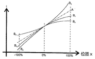
図4〜図6は、種々の力測定デバイス1についての位置・電流グラフの形態におけるシステム−特徴曲線と、それらが処理ユニット26における表示値27の算出に対して及ぼす影響とを示す。各グラフは、屈曲ピボット16または弾性リンクのおよび磁石システム19、119の理想的な挙動を伴う理想化された力測定デバイス1のシステム−特徴曲線Aと、屈曲ピボット16または弾性リンクの理想的な挙動および磁石システム19、119の現実ベースの挙動を伴う力測定デバイス1についての1つまたは複数のシステム−特徴曲線Biとを示す。水平軸上の100%および−100%に対するならびに10%および−10%に対する印が、磁石システム19、119に対するコイル20、120の変位位置を明示する。
4 to 6 show system-characteristic curves in the form of position / current graphs for various
図4においては、システム−特徴曲線Aは、直線として示されるが、これは、理想条件下において、整定位置からのコイル20、120の変位が、電流24の変化へと線形関数で変換されることを意味する。これとは対照的に、システム−特徴曲線Biは、実際に起こる状況を、すなわち磁石システム19、119の前述の不均質性を反映している。力Fが、荷重受け部12、112に対して加えられると、位置xは、変化し、位置制御ユニット23は、位置センサ21から対応する位置信号22を受領する。コイル電流IAの測定に基づき、処理ユニット26は、図4に破線矢印で示されるような表示値27を算出する。コイル20、120が、調整動作の終了時に整定位置に戻ると、その時点で測定された電流I0は、荷重受け部に対して作用する力Fに比例したものとなる。
In FIG. 4, the system-feature curve A is shown as a straight line, which means that under ideal conditions, the displacement of the
上述のように、システム−特徴曲線Aは、実際の状況を反映するには及ばず、すなわち、実際の挙動の不正確な表出に留まる。磁石システム19、119の不均質性および屈曲ピボット16または弾性リンクの非線形復元力により、図4にグラフBiで示すような少なくとも二次の伝達関数が、実際の挙動を示すためには必要となる。したがって、処理ユニットが、位置信号22、22’を受領すると、処理ユニットは、実際にはコイル電流IBに対応する表示値27を算出すべきである。システム−特徴曲線Aとシステム−特徴曲線Bとの間の不一致は、これらのシステム−特徴曲線が、整定位置周辺での磁石システム19、119の挙動に合致するため、整定位置の付近においてはより小さくなる。グラフAを使用する結果として、処理ユニット26は、表示値の算出のために不正確な電流信号を供給される。
As mentioned above, the system-feature curve A does not reflect the actual situation, i.e. it remains an inaccurate representation of the actual behavior. Due to the inhomogeneity of the
表示値の算出におけるこの問題を補正するために、本発明による処理ユニット26は、位置センサ21の位置信号22(または位置センサ28の位置信号22’)と、処理ユニット26の内部メモリに格納された伝達手段30とを、追加的にすなわちコイル電流24の規模に加えて使用する。伝達手段30は、例えば、伝達関数または伝達テーブルの形態を有し得る。すなわち、これは、本発明による伝達手段30が、秤竿17または力伝達ロッド117の全変位範囲内における複数の位置xに関する前述の伝達因子kの値を含むことを意味する。表示値27の算出においては、処理ユニット26は、処理ユニット26が受領した位置信号22、22’に基づき、および荷重受け部上の荷重に基づき、伝達因子27を選択する。換言すれば、伝達手段30は、とりわけ位置xに依存する、およびしたがって電気コイル電流24の規模と整定位置からのコイル20、120の変位量との間の相関関係を確立する、演算命令である。
In order to correct this problem in the calculation of the display value, the
上述のような伝達手段30は、秤量荷重の質量によって決定され、すなわち伝達手段30のパラメータは、秤量荷重の個々の量に関連付けられることが判明している。これは、図5において、各伝達関数B1、B2、およびB3により示される。荷重レシーバ12、112に加えられる力がより強いほど、伝達関数Biは直線グラフAからより遠く離れた曲線となる。伝達関数B3のグラフは、上方に湾曲する。この形状は、測定変換器18、118の特徴であり、力は、例えばプッシュ/プルシステムなどにおける場合のように、その方向を反転させる。したがって、伝達手段30は、伝達関数が荷重レシーバに対して作用する力と最も近く合致するか、または2つの伝達関数の各パラメータ間において補間がなされる点において、表示値27を判定するために使用される、対応するパラメータを有する少なくとも1つの伝達関数を含む。
It has been found that the transmission means 30 as described above is determined by the mass of the weighing load, ie the parameters of the transmission means 30 are related to the individual quantities of the weighing load. This is indicated in FIG. 5 by the respective transfer functions B 1 , B 2 and B 3 . The stronger the force applied to the
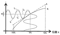
図6は、整定位置を中心とする動揺および/または振動の影響を示す。設定位置周辺のエリアが、拡大されており、そのため、x軸の可視部分は、位置xの範囲の−10%〜+10%のみに及ぶものとなっている。位置信号22、22’の動揺は、整定位置に対して対称なほぼ洞曲線として示される。システム−特徴曲線Aを有する理想化された力測定デバイス1においては、この動揺が、平均値IAmを中心として動揺する電流IAを生じさせる。実際に発生し、システム−特徴曲線Biにより図示されるような挙動では、位置xの動揺信号が、コイル電流信号IBへと変換される。実際の発生を反映したこの電流信号IBは、伝達関数により転換された非対称的に歪んだ信号であり、電流IAに対する電流IBの平均値の逸脱Mを結果的にもたらす。
FIG. 6 shows the influence of shaking and / or vibration around the settling position. The area around the set position is enlarged, so that the visible part of the x axis covers only −10% to + 10% of the range of the position x. The perturbation of the position signals 22, 22 'is shown as an approximately sinusoidal symmetry with respect to the settling position. In an idealized
電流IAおよびIBの2つの平均値を比較すると、平均値の逸脱Mが明確になる。したがって、本発明の方法を用いない場合には、表示値27は、やはり逸脱を被る。この逸脱Mは、図6において2つの相互に対向する矢印で座標軸(I軸)上に示される。 Comparing the two average values of the currents I A and I B reveals the deviation M of the average value. Therefore, if the method of the present invention is not used, the display value 27 still suffers a deviation. This deviation M is indicated on the coordinate axis (I axis) by two mutually opposite arrows in FIG.
実挙動に従った表示値27の算出を処理ユニット26が行い得るようにするために、伝達手段30が、処理ユニットのメモリに格納される。伝達手段30は、入力変数としての位置xおよびコイル電流24を用いて表示値27に対する演算命令を規定し、またパラメータも含む。前述のように、この伝達手段30は、伝達関数または伝達テーブルの形態を有し得る。
In order to enable the
伝達手段30の値および/またはパラメータは、以下のアプローチの中の1つに従って決定することが可能である。有利には、伝達手段30の値および/またはパラメータの決定は、力測定デバイス1の製造プロセスの過程で、具体的には調節局面において実施される。伝達手段30は、各力測定デバイス1に対して個別に生成することが可能であり、または、汎用伝達手段30が、同一タイプの力測定デバイス1に対して決定されてもよい。汎用伝達手段は、複数のあらかじめ決定された伝達手段30の算術平均に基づくことが可能であり、これは、後に、同一タイプの全ての力測定デバイス1に対して使用され得る。別の可能性としては、顧客の施設の設備設置場所において伝達手段30を決定するというものがある。これは、以下の説明の手順を利用することにより、短時間で完了させ得る。
The value and / or parameters of the transmission means 30 can be determined according to one of the following approaches. Advantageously, the determination of the value and / or parameter of the transmission means 30 is carried out during the manufacturing process of the
「較正」という用語は、物理的変化の発生を伴わない前述の条件下における測定量の真値からの測定値の逸脱の測定および記録の意味において使用される。この逸脱を補正するために変更を行う場合には、「調節」という用語が使用される。例えば、秤を調節する工程においては、逸脱は、熟練技術者が個別の要素の設定において変更を行うことによるその機能の手動による微調整によって、または秤の外部付属品もしくは内蔵部品である基準おもりが荷重レシーバ上に配置されることによりユーザが実施する半自動手順によって、または秤が自動作動型調節機構を備える場合には自動工程によって、補正される。 The term “calibration” is used in the sense of measuring and recording the deviation of a measured value from the true value of a measured quantity under the aforementioned conditions without the occurrence of a physical change. Where changes are made to compensate for this deviation, the term “adjustment” is used. For example, in the process of adjusting the scale, deviations may be caused by manual fine-tuning of its function by skilled technicians making changes in the settings of individual elements, or by reference weights that are external accessories or built-in parts of the scale. Is compensated by a semi-automatic procedure performed by the user by placing it on the load receiver or by an automatic process if the scale is equipped with an automatically actuated adjustment mechanism.
伝達関数30の値および/またはパラメータを決定するために可能な事柄の中でも、第1のアプローチは、コイル20、120の変位を変更し、実質的に同時に、コイル20、120の変位に関連付けられる電気コイル電流24の規模を測定することである。代替的には、第2の可能なアプローチとして、伝達関数30の値および/またはパラメータは、電気コイル電流24の規模を変更することにより、および実質的に同時に、電気コイル電流24の規模に関連付けられるコイル20、120の変位を測定することにより、決定することが可能である。
Among other things possible to determine the value and / or parameters of the
伝達関数30の値および/またはパラメータの決定の第3の可能なアプローチとしては、振動の存在下におけるコイル20、120の変位が、電気コイル電流24の規模との関連において分析される。この工程は、これを目的として特に設計された振動台に対する較正局面で、または力測定デバイス1の正常動作時に設置場所において、実施することが可能である。伝達関数30の値および/またはパラメータを決定するこの第3のアプローチは、重量選別機において優先的に使用される。
As a third possible approach for determining the value and / or parameter of the
力測定デバイス1が、荷重受け部に対して連結され、較正が必要な場合には結合および結合解除され得る、内部較正おもりを備える場合には、力測定デバイスは、前述の可能なアプローチまたはパラメータ決定の中の1つまたは複数を、メニュー制御下においてまたは自律的に実施し得る能力を有する。
If the
図7および図8のグラフは、約0.2m/s2のまたは地表での重力加速度の2%の加速度振幅で動揺する秤において梃子システム(点線)を有する最新技術の力測定デバイスとの比較において、本発明の方法により実現される表示値27(一点鎖線)の改良を示す。表示値27のこの改良は、ロバストネス(耐性)とも呼ばれる。グラフ内の横座標は、加振周波数(Hz)の単位量で目盛りが付けられ、縦軸は、荷重レシーバ上の荷重の重さに対する表示値27の逸脱の百万分率(ppm)でメモリが付けられる。図7および図8の2つのグラフは、0〜400グラムの秤量範囲を有する同一の力測定デバイス1に関する。図7は、力測定デバイスがゼロ点で、すなわち荷重受け部12上に力が加えられない状態で動作する場合の挙動を示す。図8は、400グラムの秤量荷重でのロバストネスを示す。図7および図8の両方から、この例の場合には、非常に高い最大で10倍の改良(すなわち動揺および/または振動に対する力測定デバイス1のより高度のロバストネス)が、低動揺周波数で実現され得る一方で、より高い周波数においては、一点鎖線(本発明の方法)および点線(先行技術)は、相互に漸近的に接近することが自明である。
The graphs of FIGS. 7 and 8 compare to a state-of-the-art force measurement device with a lever system (dotted line) on a scale that swings at an acceleration amplitude of about 0.2 m / s 2 or 2% of the gravitational acceleration at the surface. Fig. 5 shows an improvement of the display value 27 (dashed line) realized by the method of the present invention. This improvement of the display value 27 is also referred to as robustness. The abscissa in the graph is graduated in unit quantities of excitation frequency (Hz), and the vertical axis is the memory in parts per million (ppm) of deviation of the displayed value 27 relative to the weight of the load on the load receiver. Is attached. The two graphs of FIGS. 7 and 8 relate to the same
動的重量選別機の力測定デバイス1において本発明の方法を利用することにより、図9に図示するようなより迅速な重量測定を実現することが可能となる。秤量対象の製品は、送込みコンベヤベルトから秤量コンベヤベルトへと、および秤量コンベヤベルトから送出しコンベヤベルトへと移動する。この移動は、秤量コンベヤベルトの動揺を生じさせ、また結果的に表示値27の動揺も生じさせる。すると、位置制御ユニット23は、秤竿17または力伝達ロッド117が整定位置に戻るように、コイル電流24を調整する。先行技術の力測定デバイスを有する重量選別機の表示値の信号F’Aは、漸近曲線F’Mに倣う。この漸近曲線F’Mは、平均値の逸脱M(図6を参照)により、終値とは異なるが、動揺が鎮静化し、それと同時に平均値の逸脱Mが縮小するにつれて、終値へと徐々に整定する。本発明の方法により表示値27を決定する力測定デバイス1は、開始から終値へと整定する。この違いは、同一の電気フィルタを用いて取得され、約1.5動揺期間後に各平均値F’AおよびF’Bに到達する、2つのフィルタリングされた信号のグラフF’AmおよびF’Bmにおいて明らかである。信号F’Bmは、期間bB後には既に目標値の許容帯域内に位置するが、信号F’Amは、tBよりも長い期間tA後にようやく許容帯域内に到達する。目標値の許容帯域は、表示値27が秤量工程について必要な精度に合致し始めるしきい値を規定する。その結果、表示値27が許容帯域内により速く到達するほど、物品は秤量コンベヤベルト間をより高速で移動することが可能となる。対照的に、所要の精度を厳格化し、すなわちより狭い許容範囲を設定して、依然として同一時間tAで許容帯域内に到達することが可能である。後者のオプションでは、物品のスループットは、同一に維持され、表示値27の精度は、上昇する。
By using the method of the present invention in the
具体的な実施形態の提示により本発明を説明したが、例えば個々の実施形態の特徴を相互に組み合わせることによって、および/または個々の機能ユニットを実施形態間で交換することによってなど、本発明の教示に基づき多数のさらなる変形形態を生み出すことが可能であることは、自明である。 Although the present invention has been described by the presentation of specific embodiments, it may be possible to combine the features of the individual embodiments with each other and / or by exchanging individual functional units between the embodiments. Obviously, many additional variations can be made based on the teachings.
1 力測定デバイス
100 直接測定システムの力測定セル
11、111 固定部
12、112 荷重受け部
13 継手部材
14、114 平行ガイド
15 秤量皿
16 屈曲ピボット
17 秤竿
117 力伝達ロッド
18、118 測定変換器
19、119 磁石システム
20、120 コイル
21 位置センサ
22、22’ 位置信号
23 位置制御ユニット
24 コイル電流の規模、電流強度
25 補償力
26 処理ユニット
27 表示値
28 追加の位置センサ
30 伝達手段
A 理想化されたシステム−特徴曲線
Bi、B1、B2、B3 実際の現実ベースのシステム−特徴曲線
I0 秤竿の整定位置におけるコイル電流
IA 理想化されたシステム−特徴曲線に従って動作する際のコイル電流
IB 実際の現実ベースのシステム−特徴曲線に従って動作する際のコイル電流
IAm 理想化されたシステム−特徴曲線に従って動作する際のコイル電流の平均値
IBm 実際の現実ベースのシステム−特徴曲線に従って動作する際のコイル電流の平均値
F 荷重受け部に対して作用する力
F’ 力の算出値
x 秤竿の位置
z 擾乱量
Ti 温度信号
t 伝達関数の時間変数
M 平均値の逸脱
F’A 先行技術の重量選別機の表示値27の信号グラフ
F’B 本発明の重量選別機の表示値27の信号グラフ
F’M 目標終値から逸脱する直線セクション
F’Am 先行技術の重量選別機の表示値27のフィルタリングされた信号
F’Bm 本発明の重量選別機の表示値27のフィルタリングされた信号
tA 先行技術の重量選別機に関する許容帯域内への到達時間
tB 本発明の重量選別機に関する許容帯域内への到達時間
DESCRIPTION OF SYMBOLS 1 Force measuring device 100 Force measuring cell 11 of direct measurement system 11, 111 Fixing part 12, 112 Load receiving part 13 Joint member 14, 114 Parallel guide 15 Weighing pan 16 Bending pivot 17 Measuring rod 117 Force transmission rod 18, 118 Measuring transducer 19, 119 Magnet system 20, 120 Coil 21 Position sensor 22, 22 'Position signal 23 Position control unit 24 Coil current scale, current intensity 25 Compensation force 26 Processing unit 27 Display value 28 Additional position sensor 30 Transmission means A Idealization System-feature curve B i , B 1 , B 2 , B 3 Actual reality-based system-feature curve I 0 Coil current at settling position of I balance I A Idealized system-when operating according to feature curve coil current I B actual reality-based system - according to the characteristics curve Coil current I Am idealized system when operated - average value I Bm actual reality-based system of the coil current when operating in accordance with characteristics curve - receiving an average value F load of the coil current when operating in accordance with characteristics curve acting on parts a force F 'of the time variable M average position z disturbance amount T i temperature signal t transfer function calculated value x Hakarisao of force departing F' a prior art weight sorter display value 27 Signal graph F ′ B Signal graph of the weight sorter display value 27 of the present invention F ′ M Straight section deviating from the target closing price F ′ Am Filtered signal 27 of the prior art weight sorter display value F ′ Bm Filtered signal 27 of the weight sorter display value of the invention t A Time of arrival in tolerance band for prior art weight sorter t B Into tolerance band for weight sorter of the invention Arrival time
Claims (15)
荷重受け部(12、112)と前記測定変換器(18、118)の前記コイル(20、120)または前記磁石システム(19、119)との間の力伝達機械連結部と、
前記荷重受け部(12、112)上に荷重を加えた結果として発生する、前記磁石システム(19、119)に対する整定位置からの前記コイル(20、120)の変位を判定する役割を果たす位置センサ(21、28)であって、前記コイル(20、120)を流れる前記電流(24)は、前記コイル(20、120)と前記磁石システム(19、119)との間に電磁力を発生させる機能を有し、これにより、前記コイル(20、120)および前記コイル(20、120)または前記磁石システム(19、119)に対して連結された前記荷重受け部(12、112)は、前記整定位置へと戻されるおよび/または前記整定位置に保持される、位置センサ(21、28)と
を備える、電磁力補償の原理により作動する力測定デバイス(1)上に、荷重により印加される重量力を測定する方法において、
前記電流(24)の規模および前記整定位置からの前記コイル(20、120)の変位量が、前記印加される荷重により加えられる前記重量力を判定するために使用されることを特徴とする、方法。 Measuring transducer comprising a coil (20, 120) arranged in said magnet system (19, 119) so as to be movable relative to the magnet system (19, 119) and capable of carrying a current (24) (18, 118),
A force transmission mechanical connection between a load receiver (12, 112) and the coil (20, 120) or the magnet system (19, 119) of the measurement transducer (18, 118);
A position sensor serving to determine the displacement of the coil (20, 120) from a settling position relative to the magnet system (19, 119) generated as a result of applying a load on the load receiver (12, 112) (21, 28), and the current (24) flowing through the coil (20, 120) generates an electromagnetic force between the coil (20, 120) and the magnet system (19, 119). The load receiver (12, 112) connected to the coil (20, 120) and the coil (20, 120) or the magnet system (19, 119) A force measuring device operating according to the principle of electromagnetic force compensation comprising a position sensor (21, 28) which is returned to a settling position and / or held in said settling position. ) On a method of measuring the weight force applied by the load,
The magnitude of the current (24) and the amount of displacement of the coil (20, 120) from the settling position are used to determine the weight force applied by the applied load, Method.
前記整定位置からの前記コイル(20、120)の前記変位量は、位置制御ユニット(23)に対して入力信号を供給する前記同一の位置センサ(21)により判定され、前記位置制御ユニット(23)は、前記コイル(20、120)および前記コイル(20、120)または前記磁石システム(19、119)に対して連結された前記荷重受け部(12、112)が、前記コイル(20、120)と前記磁石システム(19、119)との間の前記電磁力により前記整定位置へと戻されるように、前記コイル(20、120)を通る前記電流(24)を調整することを特徴とする、方法。 The method for determining weight force according to claim 1,
The amount of displacement of the coil (20, 120) from the settling position is determined by the same position sensor (21) that supplies an input signal to the position control unit (23), and the position control unit (23 ), The coil (20, 120) and the load receiver (12, 112) connected to the coil (20, 120) or the magnet system (19, 119) are connected to the coil (20, 120). ) And the magnet system (19, 119), the current (24) through the coil (20, 120) is adjusted so that it is returned to the settling position by the electromagnetic force. ,Method.
前記整定位置からの前記コイル(20、120)の前記変位量は、追加の位置センサ(28)により判定されることを特徴とする、方法。 The method for determining weight force according to claim 1,
Method according to claim 1, characterized in that the amount of displacement of the coil (20, 120) from the settling position is determined by an additional position sensor (28).
前記荷重により加えられる前記重量力を判定するために、処理ユニット(26)に格納され、前記電流(24)の前記規模および前記整定位置からの前記コイル(20、120)の前記変位量を前記重量力の判定に結び付ける、算術命令を含む、伝達手段(30)が使用されることを特徴とする、方法。 In the method for determining the weight force according to any one of claims 1 to 3,
In order to determine the weight force applied by the load, the processing unit (26) stores the magnitude of the current (24) and the amount of displacement of the coil (20, 120) from the settling position. Method, characterized in that a transmission means (30) is used, including an arithmetic instruction, linked to the determination of weight force.
前記伝達手段(30)は、前記整定位置からの前記コイル(20、120)の前記変位量の値と、前記電気コイル電流(24)の前記規模の値とが、前記印加される荷重の前記重量力の値に相互に関係づけられる、伝達テーブルとして格納される、および/または、前記伝達手段(30)は、少なくとも1つのパラメータを有し、少なくとも前記電気コイル電流(24)の前記規模と前記整定位置からの前記コイル(20、120)の前記変位量とを入力量として使用する、伝達関数として格納されることを特徴とする、方法。 The method for determining weight force according to claim 4,
The transmission means (30) is configured so that a value of the displacement amount of the coil (20, 120) from the settling position and a value of the scale of the electric coil current (24) correspond to the applied load. Correlated to a value of weight force, stored as a transmission table, and / or the transmission means (30) has at least one parameter and at least the magnitude of the electric coil current (24) and Method stored as a transfer function, using as an input quantity the amount of displacement of the coil (20, 120) from the settling position.
前記伝達関数の前記少なくとも1つのパラメータは、パラメータテーブルとしておよび/またはシステム−特徴曲線として格納されることを特徴とする、方法。 The method for determining weight force according to claim 5,
Method according to claim 1, characterized in that the at least one parameter of the transfer function is stored as a parameter table and / or as a system-feature curve.
前記伝達関数の前記少なくとも1つのパラメータは、荷重依存性であることを特徴とする、方法。 The method for determining weight force according to claim 5 or 6,
The method, wherein the at least one parameter of the transfer function is load dependent.
前記伝達テーブルの前記値および/または前記伝達関数の前記少なくとも1つのパラメータは、前記コイル(20、120)の前記変位を変更し、実質的に同時に前記コイルの前記変位に関連付けられる前記電気コイル電流(24)の前記規模を測定することにより、および/または、前記電気コイル電流(24)の前記規模を変更し、実質的に同時に前記電気コイル電流(24)の前記規模に関連付けられる前記コイル(20、120)の前記変位を測定することにより、および/または、振動の存在下において前記電気コイル電流(24)の前記規模に対する前記コイル(20、120)の前記変位を分析することにより、決定されることを特徴とする、方法。 In the method for determining weight force according to any one of claims 5 to 7,
The value of the transfer table and / or the at least one parameter of the transfer function changes the displacement of the coil (20, 120) and is substantially simultaneously associated with the displacement of the coil. Measuring said magnitude of (24) and / or changing said magnitude of said electric coil current (24) and substantially simultaneously said coil associated with said magnitude of said electric coil current (24) ( 20), 120) and / or by analyzing the displacement of the coil (20, 120) relative to the magnitude of the electrical coil current (24) in the presence of vibration. A method, characterized in that
前記伝達テーブルの前記値の前記決定および/または前記伝達関数の前記少なくとも1つのパラメータの前記決定は、前記荷重受け部(12、112)に加えられる重量がある状態およびない状態の両方においてなされ、前記重量は、外部から前記荷重受け部(12、112)に対して加えられる重量か、または機構により内部的に加えられ得る重量のいずれかであることが可能であることを特徴とする、方法。 The method for determining weight force according to claim 8,
The determination of the value of the transfer table and / or the determination of the at least one parameter of the transfer function is made both with and without weight applied to the load receiver (12, 112); The method can be characterized in that the weight can be either externally applied to the load receiver (12, 112) or weight that can be applied internally by a mechanism. .
前記伝達手段(30)は、各力測定デバイス(1)に対して個別に、または同一タイプの力測定デバイス(1)に対して汎用的に生成されることを特徴とする、方法。 The method for determining weight force according to any one of claims 4 to 9,
Method, characterized in that the transmission means (30) are generated individually for each force measuring device (1) or universally for the same type of force measuring device (1).
時間信号および少なくとも1つの温度信号が、入力量として追加的に使用されることを特徴とする、コンピュータプログラム。 The computer program according to claim 12, for implementing the method for determining weight force.
A computer program, characterized in that a time signal and at least one temperature signal are additionally used as input quantities.
前記コンピュータプログラムは、請求項3から10のいずれか一項に記載の伝達手段(30)を呼び出すことを特徴とする、コンピュータプログラム。 14. A computer program according to claim 12 or 13 for implementing the method for determining weight force.
Computer program, characterized in that the computer program calls the transmission means (30) according to any one of claims 3 to 10.
重量力の判定が、請求項12から14のいずれか一項に記載のコンピュータプログラムにより端末において実施されることを特徴とする、重量選別システム。 Weighing an object comprising an infeed conveyor belt for carrying in a weighing object, a feeding conveyor belt for carrying out the weighing object, and a weighing conveyor belt connected to a force measuring device (1) In the weight sorting system that plays a role,
A weight selection system, wherein the determination of weight force is performed at a terminal by the computer program according to any one of claims 12 to 14.
Applications Claiming Priority (2)
| Application Number | Priority Date | Filing Date | Title |
|---|---|---|---|
| EP13161569.2A EP2784453B1 (en) | 2013-03-28 | 2013-03-28 | Digital weighing cell linearization |
| EP13161569.2 | 2013-03-28 |
Publications (2)
| Publication Number | Publication Date |
|---|---|
| JP2014197001A JP2014197001A (en) | 2014-10-16 |
| JP6335576B2 true JP6335576B2 (en) | 2018-05-30 |
Family
ID=48013828
Family Applications (1)
| Application Number | Title | Priority Date | Filing Date |
|---|---|---|---|
| JP2014065641A Active JP6335576B2 (en) | 2013-03-28 | 2014-03-27 | Digital linearization in weighing cells |
Country Status (5)
| Country | Link |
|---|---|
| US (1) | US20140291040A1 (en) |
| EP (1) | EP2784453B1 (en) |
| JP (1) | JP6335576B2 (en) |
| CN (1) | CN104075783B (en) |
| PL (1) | PL2784453T3 (en) |
Families Citing this family (7)
| Publication number | Priority date | Publication date | Assignee | Title |
|---|---|---|---|---|
| CN104697614A (en) * | 2015-03-12 | 2015-06-10 | 南车株洲电力机车有限公司 | Magnetically levitated train load information generating system |
| EP3203180B1 (en) * | 2016-02-04 | 2018-12-05 | Mettler-Toledo GmbH | Apparatus and methods for dimensioning an object carried by a vehicle moving in a field of measurement |
| WO2017135892A1 (en) * | 2016-02-04 | 2017-08-10 | Nanyang Technological University | Method and arrangement for determining at least one pore-related parameter of a porous structure |
| DE102017127690B4 (en) * | 2017-11-23 | 2023-03-02 | Sartorius Lab Instruments Gmbh & Co. Kg | Method for generating a result value in an electromagnetically compensating weighing device |
| CN110702194A (en) * | 2019-07-29 | 2020-01-17 | 辽宁维森信息技术股份有限公司 | High-speed weighing controller with automatic compensation function and control method |
| CN114543955B (en) * | 2020-11-25 | 2024-04-09 | 菜鸟智能物流控股有限公司 | Weighing device, weighing processing method, device, equipment and machine-readable medium |
| CN117075568B (en) * | 2023-10-18 | 2024-01-05 | 绵阳沃思测控技术有限公司 | Batching control system based on continuous monitoring |
Family Cites Families (14)
| Publication number | Priority date | Publication date | Assignee | Title |
|---|---|---|---|---|
| JPS5723825A (en) * | 1980-07-17 | 1982-02-08 | Shimadzu Corp | Electronic direct indication balance |
| JPS62133321A (en) * | 1985-12-05 | 1987-06-16 | Yamato Scale Co Ltd | Correcting device for dynamic metered value of metering conveyor |
| JPS62193528U (en) * | 1986-05-30 | 1987-12-09 | ||
| US4802541A (en) * | 1988-03-11 | 1989-02-07 | Pitney Bowes Inc. | Weighing scale with voice coil |
| DE3829637C1 (en) | 1988-09-01 | 1990-04-12 | Sartorius Gmbh, 3400 Goettingen, De | |
| JP3312626B2 (en) | 1989-12-01 | 2002-08-12 | 株式会社石田衡器製作所 | Load cell type weight measuring device |
| JP2518125B2 (en) * | 1992-05-28 | 1996-07-24 | 株式会社島津製作所 | Electronic balance |
| JP3620168B2 (en) * | 1996-09-30 | 2005-02-16 | 株式会社島津製作所 | Electronic balance |
| DE10046205C2 (en) * | 2000-09-13 | 2002-09-12 | Francotyp Postalia Ag | Process for controlling a fast dynamic balance |
| US6759602B2 (en) * | 2001-05-08 | 2004-07-06 | Pitney Bowes Inc. | Apparatus and method for weighing mailpieces in motion |
| US7247801B2 (en) | 2002-06-07 | 2007-07-24 | Pitney Bowes Inc. | System and method for fast weighing of items such as mailpieces |
| DE102004054999B3 (en) * | 2004-11-15 | 2006-03-30 | Francotyp-Postalia Gmbh | Weighing machine for moving postal packages has short conveyer belt with end rollers on weighing platform and has entry and exit sensors noting passage of front and rear end of each passage |
| DE102010009431A1 (en) * | 2010-02-24 | 2011-08-25 | Francotyp-Postalia GmbH, 16547 | Fast dynamic balance and method for controlling a fast dynamic balance |
| JP5658594B2 (en) * | 2011-02-24 | 2015-01-28 | アンリツ産機システム株式会社 | Weighing device |
-
2013
- 2013-03-28 EP EP13161569.2A patent/EP2784453B1/en active Active
- 2013-03-28 PL PL13161569T patent/PL2784453T3/en unknown
-
2014
- 2014-03-27 JP JP2014065641A patent/JP6335576B2/en active Active
- 2014-03-27 CN CN201410119771.2A patent/CN104075783B/en active Active
- 2014-03-28 US US14/228,861 patent/US20140291040A1/en not_active Abandoned
Also Published As
| Publication number | Publication date |
|---|---|
| CN104075783A (en) | 2014-10-01 |
| EP2784453A1 (en) | 2014-10-01 |
| CN104075783B (en) | 2019-06-18 |
| EP2784453B1 (en) | 2018-10-10 |
| PL2784453T3 (en) | 2019-04-30 |
| US20140291040A1 (en) | 2014-10-02 |
| JP2014197001A (en) | 2014-10-16 |
Similar Documents
| Publication | Publication Date | Title |
|---|---|---|
| JP6335576B2 (en) | Digital linearization in weighing cells | |
| US10132672B2 (en) | Digital linearization in a weighing cell | |
| JP6212313B2 (en) | Force measuring device with feeding weight | |
| US7906737B2 (en) | Electronic scale comprising an inclinometer and corresponding signal evaluation method | |
| US7282655B2 (en) | Electronic balance having a position control mechanism | |
| US7964806B2 (en) | Electronic scale comprising a bubble level | |
| EP1531134A1 (en) | Vibrating transport apparatus and method of detecting vibration characteristic | |
| US20060161386A1 (en) | Weighing system using electromagnetic force compensation | |
| US2793026A (en) | Spring balance for rapid continuous dosing or controlling | |
| US4129189A (en) | Weight control system | |
| JPH0568645B2 (en) | ||
| US3142349A (en) | Dynamically compensated weighing scales | |
| CN104121970B (en) | A kind of signal processing method of belted electronic balance | |
| CN107091677B (en) | Error compensation method and belt scale based on error compensation | |
| JP3834141B2 (en) | Vibratory conveying device for goods | |
| JP3836969B2 (en) | Vibratory conveying device for goods | |
| US11274960B2 (en) | Calibration and support platform for calibration weights on a conveyor and metering device | |
| USRE28303E (en) | Iiynamically compensated weighing scales | |
| EP1194754B1 (en) | Conveyor scale for controlling rock wool surface density | |
| JPH07294317A (en) | Electronic balance | |
| US559374A (en) | Price-scale | |
| US1339759A (en) | Scale | |
| JPH0577969B2 (en) | ||
| US1251016A (en) | Automatic weight-indicating attachment for beam-scales. | |
| JP2002174545A (en) | Force balance |
Legal Events
| Date | Code | Title | Description |
|---|---|---|---|
| A621 | Written request for application examination |
Free format text: JAPANESE INTERMEDIATE CODE: A621 Effective date: 20170202 |
|
| A977 | Report on retrieval |
Free format text: JAPANESE INTERMEDIATE CODE: A971007 Effective date: 20171011 |
|
| A131 | Notification of reasons for refusal |
Free format text: JAPANESE INTERMEDIATE CODE: A131 Effective date: 20171016 |
|
| TRDD | Decision of grant or rejection written | ||
| A01 | Written decision to grant a patent or to grant a registration (utility model) |
Free format text: JAPANESE INTERMEDIATE CODE: A01 Effective date: 20180402 |
|
| A61 | First payment of annual fees (during grant procedure) |
Free format text: JAPANESE INTERMEDIATE CODE: A61 Effective date: 20180501 |
|
| R150 | Certificate of patent or registration of utility model |
Ref document number: 6335576 Country of ref document: JP Free format text: JAPANESE INTERMEDIATE CODE: R150 |
|
| R250 | Receipt of annual fees |
Free format text: JAPANESE INTERMEDIATE CODE: R250 |
|
| R250 | Receipt of annual fees |
Free format text: JAPANESE INTERMEDIATE CODE: R250 |
|
| R250 | Receipt of annual fees |
Free format text: JAPANESE INTERMEDIATE CODE: R250 |