JP6335171B2 - Concentrator - Google Patents
Concentrator Download PDFInfo
- Publication number
- JP6335171B2 JP6335171B2 JP2015528692A JP2015528692A JP6335171B2 JP 6335171 B2 JP6335171 B2 JP 6335171B2 JP 2015528692 A JP2015528692 A JP 2015528692A JP 2015528692 A JP2015528692 A JP 2015528692A JP 6335171 B2 JP6335171 B2 JP 6335171B2
- Authority
- JP
- Japan
- Prior art keywords
- gas flow
- hair
- air
- nozzle
- conduit
- Prior art date
- Legal status (The legal status is an assumption and is not a legal conclusion. Google has not performed a legal analysis and makes no representation as to the accuracy of the status listed.)
- Active
Links
Images


Classifications
-
- A—HUMAN NECESSITIES
- A45—HAND OR TRAVELLING ARTICLES
- A45D—HAIRDRESSING OR SHAVING EQUIPMENT; EQUIPMENT FOR COSMETICS OR COSMETIC TREATMENTS, e.g. FOR MANICURING OR PEDICURING
- A45D20/00—Hair drying devices; Accessories therefor
-
- A—HUMAN NECESSITIES
- A45—HAND OR TRAVELLING ARTICLES
- A45D—HAIRDRESSING OR SHAVING EQUIPMENT; EQUIPMENT FOR COSMETICS OR COSMETIC TREATMENTS, e.g. FOR MANICURING OR PEDICURING
- A45D20/00—Hair drying devices; Accessories therefor
- A45D20/04—Hot-air producers
- A45D20/08—Hot-air producers heated electrically
- A45D20/10—Hand-held drying devices, e.g. air douches
- A45D20/12—Details thereof or accessories therefor, e.g. nozzles, stands
- A45D20/122—Diffusers, e.g. for variable air flow
Description
関連出願の相互参照
本国際特許出願は、2012年8月24日付けで出願された「コンセントレータ」と題する米国仮特許出願第61/693,136号明細書および2012年11月9日付けで出願された「コンセントレータ」と題する米国特許出願第12/673,706号明細書に関し、それらの利益を主張するものであり、それらの全内容は参照により本明細書に援用される。
CROSS REFERENCE TO RELATED APPLICATIONS This international patent application is filed on US Provisional Patent Application No. 61 / 693,136 entitled “Concentrator” filed on August 24, 2012 and November 9, 2012. No. 12 / 673,706, entitled “Concentrator”, which claims the benefit thereof, the entire contents of which are hereby incorporated by reference.
毛髪乾燥装置は、毛髪を乾燥させ、所望のスタイルに形作るための温風の流れを送り出す。毛髪乾燥装置からの気流を分散させ、それによってカール、縮れのない毛髪本体および毛髪の質感を作るために、ディフューザが一般に使用される。特定の状況下では、特定のヘアスタイルを得るために毛髪乾燥もしくはスタイリング装置、またはそのアタッチメントの設計を修正することが望ましい。 The hair drying device delivers a stream of warm air to dry the hair and shape it into the desired style. Diffusers are commonly used to disperse the airflow from the hair drying device, thereby creating a curled, non-curly hair body and hair texture. Under certain circumstances, it may be desirable to modify the design of the hair drying or styling device, or its attachment, to obtain a specific hairstyle.
消費者はしばしば、自分の毛髪をプロにブロー乾燥してもらい、サロンスタイルの仕上がりを手に入れるために高いお金を払う。美容師は、毛髪の特定の部分を一度で乾燥およびスタイリングすることによって、入念に施術を行う。毛髪を乾燥させる際、美容師はブラシを使用し、毛髪の小さい部分を選択して、繰り返し毛髪に熱を当てる。特定の部分に熱を集中させ、同時に所望の方向にブラシを引くことによって、乾燥工程においてボリュームおよび光沢も作りながら毛髪を形作る。例えば、ドライヤーからの加熱空気を当て、ブラシを毛髪の端部に向かって下方に引くと、滑らかな仕上がりが得られる。 Consumers often pay high money to get their hair professionally blow-dried and get a salon-style finish. The hairdresser carefully performs the procedure by drying and styling certain parts of the hair at once. When drying the hair, the hairdresser uses a brush to select small portions of the hair and repeatedly heat the hair. By concentrating heat on a specific part and simultaneously brushing in the desired direction, the hair is shaped while also creating volume and gloss in the drying process. For example, by applying heated air from a dryer and pulling the brush downward toward the end of the hair, a smooth finish can be obtained.
性能を改善するための毛髪乾燥装置への修正を、米国特許第3,563,250号明細書、第5,956,863号明細書、第3,939,850号明細書、第6,199,295号明細書および第5,316,025号明細書に見ることができる。しかしながら、これらの修正のそれぞれには、複雑さ、高コストおよび限られた有効性などの1つまたは複数の欠点がある。例えば、ほとんどのヘアドライヤーの修正物は扱いにくい構造を有し、乾燥工程が、ユーザにとってさらに一層困難になり、面倒で苛立たしくなり得る。 Modifications to the hair drying device to improve performance are described in US Pat. Nos. 3,563,250, 5,956,863, 3,939,850, 6,199. , 295 and 5,316,025. However, each of these modifications has one or more drawbacks such as complexity, high cost and limited effectiveness. For example, most hair dryer modifications have a cumbersome structure, and the drying process can become even more difficult, cumbersome and frustrating for the user.
典型的には、ヘアドライヤーは、空気吸込口および空気吹出口を画定する送風機を収容する管状本体を有する。環境から空気吸込口に空気を吸い込む内部ファンを運転するために、電気モータが設けられる。空気は一般に、加熱要素を横切って空気吹出口の方へ送り込まれる。加熱空気は、空気吹出口を通って、空気吹出口を囲む本体から流れ出る。円形断面により、毛髪の表面は乾燥し、平らになるが、毛髪の下部はより長い時間濡れたままである。 Typically, a hair dryer has a tubular body that houses a blower that defines an air inlet and an air outlet. An electric motor is provided to operate an internal fan that draws air from the environment into the air inlet. Air is generally fed across the heating element toward the air outlet. The heated air flows out of the body surrounding the air outlet through the air outlet. Due to the circular cross section, the surface of the hair dries and flattens, but the lower part of the hair remains wet for a longer time.
付属品が取り付けられていない従来の毛髪乾燥装置は、円形断面の流れパターンを有する。付属品は、ヘアドライヤーの空気吹出口を囲む本体に取り付けることができる。加熱空気は本体を通って流れ、空気吹出口から出て、空気の流れパターンを変える付属品を通る。ヘアドライヤーからの空気の流れパターンを変えるものとして、米国特許第D426674号明細書、同第4538362号明細書、同第71521610号明細書、同第D440354号明細書および仏国特許第2888095号明細書に記載のものなどの様々な付属品が知られている。しかしながら、これらのそれぞれには、効率が悪く、ボリュームを出したり、滑らかな仕上がりのヘアスタイルを作ったりすることができないという1つまたは複数の欠点がある。 Conventional hair drying devices without attachments have a circular cross-sectional flow pattern. The accessory can be attached to the body surrounding the air outlet of the hair dryer. Heated air flows through the body, exits the air outlet, and passes through accessories that change the air flow pattern. US Pat. Nos. 4,426,674, 4,538,362, 7,152,610, 4,440,354 and French Patent 2,888,095 are examples of changing the air flow pattern from a hair dryer. Various accessories are known such as those described in. However, each of these has one or more disadvantages of being inefficient and incapable of producing a volume or creating a smooth finished hairstyle.
先の理由により、従来の装置の欠点を克服する毛髪処理装置が必要とされている。 For the foregoing reasons, there is a need for a hair treatment device that overcomes the shortcomings of conventional devices.
本発明の特徴を有する毛髪処理装置は、上記のニーズを満たす。例示的装置は、本体と、本体によって支持された、空気を吹き出す送風機とを有する。送風機に分離可能に連結された、または送風機と一体化されたコンセントレータが、送風機と気体流連通する少なくとも1つの気体流導管を備える。ノズルが、導管の遠位部と気体流連通し、第1の導管の遠位部から本体の方へ空気を吹き戻すように配向している。 The hair treatment apparatus having the features of the present invention satisfies the above needs. An exemplary device has a main body and a blower that blows air supported by the main body. A concentrator detachably coupled to or integrated with the blower includes at least one gas flow conduit in gas flow communication with the blower. A nozzle is in gas flow communication with the distal portion of the conduit and is oriented to blow air back from the distal portion of the first conduit toward the body.
有利なことには、気体流導管は長手軸を有し、ノズルは、毛髪の外表面上に空気を方向付けるように、長手軸に対して100度を超える角度で気体流導管の遠位部から本体の方へ空気を方向付ける。 Advantageously, the gas flow conduit has a longitudinal axis and the nozzle is at a distal portion of the gas flow conduit at an angle greater than 100 degrees relative to the longitudinal axis so as to direct air onto the outer surface of the hair. Direct the air from the head toward the body.
本体は、そのような気体流導管を2つの備え、各気体流導管は、それぞれの導管と気体流連通するノズルを有し、両ノズルは、それぞれの導管の遠位部から本体の方へ空気を吹き出すように配向している。好ましくは、導管の長手軸は互いに平行である。ノズル吹出口の直径は、空気を集中させてその速度を増加させるために、気体流導管の直径より小さくなり得る。 The body comprises two such gas flow conduits, each gas flow conduit having a nozzle in gas flow communication with the respective conduit, both nozzles air from the distal portion of the respective conduit toward the body. Oriented to blow out. Preferably, the longitudinal axes of the conduits are parallel to each other. The diameter of the nozzle outlet can be smaller than the diameter of the gas flow conduit in order to concentrate air and increase its velocity.
毛髪処理装置は、任意選択でバーを有することができ、バーは、2つの気体流導管の間に位置決めされた突出剛毛を任意選択で有する。突出剛毛を備えたバーは装置上に位置決めされているため、ノズルから出る空気は、装置の剛毛部と交差する。剛毛部は、ユーザの毛髪と係合するように使用することができる。バーは、装置に永久的に取り付けることができ、またはユーザがバーを外すことができるように挿入可能であり得る。脱着可能な特徴により、様々な寸法または剛毛特性のバーを毛髪処理装置に挿入することができる。例えば、剛毛部はブラシのような構造または櫛のような構造をより多く有し得る。バーは、空気がバーの中を移動しないように中実構造であり得、またはバーの内部が、装置を通る追加の空気流路を作る中空であり得る。バーが中空構造を有する場合、ノズルと同様に装置の剛毛部からも空気が出るように、バーは任意選択でアパーチャを有し得る。 The hair treatment device can optionally have a bar, and the bar optionally has protruding bristles positioned between two gas flow conduits. Since the bar with protruding bristles is positioned on the device, the air exiting the nozzle intersects the bristles of the device. The bristles can be used to engage the user's hair. The bar can be permanently attached to the device or can be insertable so that the user can remove the bar. The removable feature allows bars of various sizes or bristle properties to be inserted into the hair treatment device. For example, the bristles may have more brush-like structures or comb-like structures. The bar may be solid so that air does not move through the bar, or the interior of the bar may be hollow creating an additional air flow path through the device. If the bar has a hollow structure, the bar may optionally have an aperture so that air exits the bristles of the device as well as the nozzle.
本体は、筒状に形作られ、本体の一端部には位置決めされた気体導管部と、他端部にはユーザの手に収まるように寸法が合わされた把持部とが備えられてもよい。あるいは、筒状に形作られた本体がある場合、装置はその本体に実質的に垂直に位置決めされた把持部を有することができ、スイッチはその把持部上に位置決めされ得る。 The main body may be formed in a cylindrical shape, and may be provided with a gas conduit portion positioned at one end portion of the main body and a grip portion having a dimension adjusted to fit in a user's hand at the other end portion. Alternatively, if there is a cylindrically shaped body, the device can have a gripping portion positioned substantially perpendicular to the body and the switch can be positioned on the gripping portion.
装置の使用時には、ユーザは毛髪処理装置を把持し、送風機を作動させ、それによって空気が任意選択の加熱アセンブリを通って、続いて1つまたは複数の気体流導管、および1つまたは複数のノズルを通って送られる。ノズルは、空気を本体の方へ方向付ける。ユーザは、方向付けられた空気が剛毛部と共に毛髪と係合する場所に毛髪を配置し、それによって毛髪を乾燥させ、スタイリングする。 In use of the device, the user grips the hair treatment device and activates the blower, whereby air passes through the optional heating assembly, followed by one or more gas flow conduits, and one or more nozzles Sent through. The nozzle directs air toward the body. The user places the hair where directed air engages the hair along with the bristles, thereby drying and styling the hair.
コンセントレータが送風機と一体化されていない場合、コンセントレータは、(a)コンセントレータの吸込口を毛髪器具の吹出口に被せるステップ、b)空気がノズルから吹き出す場所に毛髪を配置するステップ、およびc)ステップ(b)の前または後に、毛髪器具を作動させて、コンセントレータを通して加熱空気を吹き出すステップによって使用することができる。 If the concentrator is not integrated with the blower, the concentrator (a) covers the air outlet of the concentrator over the outlet of the hair appliance, b) places the hair where air blows out of the nozzle, and c) step. Before or after (b), the hair device can be activated and used by blowing heated air through a concentrator.
本発明のこれらならびに他の特徴、態様および利点は、以下の説明、添付の特許請求の範囲、および添付図面を参照してよりよく理解される。 These and other features, aspects and advantages of the present invention will be better understood with reference to the following description, appended claims, and accompanying drawings.
本発明は、毛髪を乾燥させ、スタイリングすることができる毛髪処理装置、およびそれを行うための方法を対象とする。以下の説明では、本発明の実施形態をより完全に説明するために、多くの具体的な詳細について述べる。しかしながら、これらの具体的な詳細がなくても本発明の実施形態を実施し得ることは、当業者に明らかである。他の例では、本発明を不明瞭にしないように、よく知られている特徴については詳細に説明していない。 The present invention is directed to a hair treatment device capable of drying and styling hair and a method for doing so. In the following description, numerous specific details are set forth in order to provide a more thorough explanation of embodiments of the present invention. However, it will be apparent to those skilled in the art that embodiments of the present invention may be practiced without these specific details. In other instances, well-known features have not been described in detail so as not to obscure the present invention.
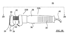
図1Aおよび図2Aを参照すると、毛髪処理装置20は、本体部22Aおよびコンセントレータ部22Bを有する本体22と、内部空洞24とを備える。本体22によって支持された送風機26は、空胴24内にある。コンセントレータ部22Bは、少なくとも1つ、好ましくは2つの気体流導管28を備え、各気体流導管28は、送風機26と気体流連通する近位部30と、それぞれの導管28と気体流連通する少なくとも1つのノズル34を有する遠位部32とを有する。ノズル34は、導管28の遠位部32から本体22の方へ空気を方向付けるように配向している。毛髪処理装置20の加熱および/または動作速度を制御するために、スイッチ36が本体部22A上、または別の適切な場所に位置し得る。本体部22Aの外部には、装置20を使用しやすいように把持突出部38を設けることができる。任意選択で突出剛毛42を備えた任意のバー40が、ユーザの毛髪と係合するように、導管28間の装置20上に位置し得る。
1A and 2A, the
気体導管28部は、管状本体22の軸方向の一端部に位置し、強制空気の気流を所望のパターンに方向付けており、一方ユーザのための把持突出部38は、本体22の軸方向の他端部に位置する。
The
図1に示すような装置20は、馬蹄型構造の2つの平行な気体導管28を備えた好ましい実施形態を示す。それら気体導管28はそれぞれ、平行な長手軸を有する。2つの平行な気体流導管28は、協働して空気を共通点の方へ方向付ける。2つ以上の気体導管28を有することによって、ノズル34から出る空気が共通点で集中する。2つの気体導管28間の距離は、約1インチ〜約6インチであり得る。
A
好ましくは、導管28の長手軸に対して100度を超える角度でノズル34によって空気が本体22の方へ方向付けられるように、ノズル34が配向している。好ましい実施形態では、ノズル34の内径は、気体流導管28の内径より小さい。ノズル34の開口部は、毛髪が開口部に吸い込まれないように、任意選択によりスクリーンまたはメッシュで覆うことができる。
Preferably, the
バー40は、ノズル34から出る空気が剛毛42と交差する場所に位置し得る。突出剛毛42を備えたバー40は、装置20の本体22に永久的に固定することができ、または様々な寸法および異なる剛毛特性のバー40を使用することができるように脱着可能であり得る。バー40の断面は、正方形、矩形、円形、または装置の設計に適した任意の形状であり得る。様々な寸法または剛毛特性を備えたバー40を有することによって、得られるヘアスタイル能力を変えることができる。剛毛42は、雄豚剛毛、ナイロンもしくは他のプラスチック剛毛を含むヘアブラシ剛毛のタイプ、または雄豚およびプラスチック剛毛などの剛毛タイプの組合せであり得る。雄豚およびプラスチック剛毛は、薄いまたは細い毛髪には柔らかい剛毛、濃いまたは硬い毛髪には堅い剛毛など、異なるブラッシング用途に対して堅さを変えることができる。ナイロンまたはプラスチック剛毛は、頭皮を引っ掻かないように、丸みを帯びた、または球状の端部を有し得、さらに他のヘアブラッシング用途に対して、雄豚剛毛と、プラスチックまたはナイロン剛毛とを1つのブラシの中に組み合わせてもよい。突出部には、トルマリン剛毛、シリコン剛毛もしくはシリコンコーティング剛毛、または、縮れを低減し、毛髪の滑らかさおよびもつれを改善する他の剛毛コーティングなどの他の選択肢も使用してよい。突出剛毛42を備えたバー40は、中実構造であり得、または内部中空空胴を有し得る。任意選択で、バー40が内部中空空胴を有する場合、バー40は、空気がバー40から出て、剛毛42を通って流れ得るアパーチャを有し得る。
The
図1Bは、突出剛毛42を備えたより大きい寸法のバー40を収容することができる代替本体22の設計を有する毛髪処理装置の別の変形例を示す。この変形例では、突出剛毛42を備えたバー40は中空であり、送風機26からの強制空気が遠位の気体流導管28およびノズル34に入るように流路を作る。
FIG. 1B shows another variation of a hair treatment device having an
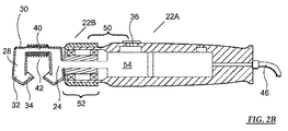
図2Aおよび図2Bに示すように、外気が本体部22Aの内部空洞24に引き込まれ、内部空洞24を通って気体連通路へ入り、その結果、送風機26によって装置20の本体22を通って圧力下で空気が送られる。
As shown in FIGS. 2A and 2B, the outside air is drawn into the
ヘアドライヤーで典型的であるように、本体部22Aは送風機26およびその構造要素を収容する。送風機26は一般に、電源コード46によってAC電源などの電源と電気的に接続されている、本体22の内部に位置するファンを運転するためのモータを備える。本体22の中を通って移動する気流を加熱するためのヒータが、典型的には本体22内にある。この変形例によれば、ヒータアセンブリ52およびファンアセンブリ54を含む加熱送風機50が使用される。一例示的変形例では、ヒータアセンブリ52が、電源コード46または他の手段を介して電流が供給される抵抗器の役目を果たす。加熱要素を有するヘアスタイリング器具の他の例が、米国特許第7,631,646号明細書および第7,481,228号明細書に見られ得、それらの全開示が参照によって本明細書に援用される。
As is typical for a hair dryer, the
ここで図3を参照すると、コンセントレータ60を毛髪送風機26と一体化させるのではなく、コンセントレータ60は、送風機26を有する毛髪器具70に取り外し可能に取り付けることができる単独のユニットであり得る。好ましい実施形態では、毛髪器具70はヘアドライヤーである。一般に、ヘアドライヤーの空気吹出口62は管状すなわち円形開口部を有し、同様に、コンセントレータ60の吸込口64部は管状であり、断面が円形である。毛髪器具70を作動させる前または後に、コンセントレータ60を毛髪器具70に被せることができる。
Referring now to FIG. 3, rather than integrating the
この変形例では、コンセントレータ60の本体22は、中央円錐部66および排出端部68を有し、中央円錐部66は、吸込口64部と排出端部68との間にあり、中を通る気体流路を画定している。好ましい実施形態では、コンセントレータ60の本体22は、馬蹄型構造の2つの平行な気体導管28を画定する。本体22は、金属、もしくはプラスチックすなわちポリプロピレン、またはそれらの組合せなどの、毛髪器具70、ヘアドライヤーおよびヘアドライヤーアタッチメントに従来使用されている様々な材料からなり得る。
In this modification, the
図4から見てわかるように、本体22の内部空洞24を通って流れる空気は、本体22と気体流連通している気体導管28に分流される。次いで、空気は気体導管28を通過し、続いて図3に示すようなノズル34を通過して共通点に向かう。突出剛毛42を備えたバー40は、共通点に位置する。
As can be seen from FIG. 4, the air flowing through the
図5では、コンセントレータ60の底面図により、コンセントレータ60の内部空洞24が示される。空気は、送風機26から気体流導管28に方向付けられ、図3に示すようなノズル34を通ることによって、空気を集中させる。ノズル34の内径が気体流導管28の内径より小さい場合、空気はノズル34から出る前にさらに集中する。
In FIG. 5, the bottom view of the
図6は、毛髪器具70に取り付けられたコンセントレータ60を示す。この図では、コンセントレータ60は、毛髪器具70に取り外し可能に取り付けることができるアタッチメントとして構成される。コンセントレータ60が取り付けられると、毛髪器具70における他の従来の気流が集中する。プロのセッティング時または家庭での使用には、分離可能なアダプタとして構成される場合、乾燥が完了したらコンセントレータ60を外すことがしばしば望ましい。コンセントレータ60を外すと、ここで代替の毛髪乾燥アタッチメントを毛髪器具70と共に使用することができる。
FIG. 6 shows the
本発明の特徴が、毛髪器具70へのアタッチメントとして構成されるか、それとも送風機26と一体化されるかにかかわらず、ユーザは、処理すべき毛髪の部分を選択しながら、片手で装置20または毛髪器具70を保持するだけでよい。毛髪の一部と係合したら、集中した空気を当てながら、毛髪をユーザから遠ざかるように引く。
Regardless of whether the features of the present invention are configured as an attachment to the
装置20が送風機26と一体化されている場合、ユーザに非常に便利なヘアドライヤーを使用することなく毛髪を加熱し、同時にスタイリングしてもよい。装置20を作動させると、突出剛毛42を備えたバー40は、ユーザの毛髪と係合し得る。突出剛毛42を備えたバー40と共に、集中した空気がユーザの毛髪と係合することによって、毛髪をユーザの頭皮から遠ざかるように持ち上げる。その結果、毛髪の係合された部分が、1つまたは複数のノズル34から出る空気によって乾燥する。ユーザがさらに、自分の頭から遠ざかるように装置20を引くと、毛髪は持ち上げられ、ブラシのような方法で剛毛部42上を滑るように進む。その結果、空気が毛髪の中を一様に移動し、滑らかなに毛髪を乾燥させる。この方法を用いて毛髪を乾燥させることによって、ボリュームのある滑らかな仕上がりが得られる。
If the
コンセントレータ60が、毛髪を乾燥させ、スタイリングするためのアタッチメントとして使用される際、ユーザは、上で説明したようなコンセントレータ60を、吹出口62を有する毛髪器具70に被せる。コンセントレータ60の吸込口64部は、毛髪器具70の吹出口62に近接しており、毛髪器具70が作動して、通常加熱される空気を、コンセントレータ60を通して吹き出す。
When the
さらに、様々な実施形態の態様を全体的または部分的に交換してもよいことを理解されたい。さらに当業者であれば、先の記述は単なる例としてのものであり、添付の特許請求の範囲にさらに記載する本発明を限定するものではないことを理解する。 Further, it should be understood that aspects of the various embodiments may be interchanged in whole or in part. Furthermore, those skilled in the art will appreciate that the foregoing description is by way of example only and is not intended to limit the invention as further described in the appended claims.
Claims (12)
(b)前記本体によって支持された送風機と、
(c)前記送風機と気体流連通する第1の気体流導管において、長手軸、前記本体によって支持された近位部、および前記本体から離れた遠位部を有する第1の気体流導管と、
(d)前記第1の気体流導管の前記遠位部と気体流連通し、前記長手軸に対して100度を超える角度で前記第1の気体流導管の前記遠位部から前記本体の方へ空気を吹き出すように配向した第1のノズルと、
(e)前記送風機と気体流連通する第2の気体流導管において、長手軸、前記本体によって支持された近位部、および前記本体から離れた遠位部を有する第2の気体流導管と、
(f)前記第2の気体流導管の前記遠位部と気体流連通し、前記長手軸に対して100度を超える角度で前記第2の気体流導管の前記遠位部から前記本体の方へ空気を吹き出すように配向した第2のノズルと、
(g)前記第1の気体流導管と前記第2の気体流導管との間に位置する突出剛毛を備えたバーにおいて、前記第1のノズルおよび前記第2のノズルから前記バーの表面上に横断して空気が吹き出すように位置決めされ、毛髪を前記バーに被せてとかすと前記毛髪が滑らかになり、艶が出るバーと
を備えることを特徴とする毛髪処理装置。 (A) a main body;
(B) a blower supported by the main body;
(C) a first gas flow conduit in gas flow communication with the blower having a longitudinal axis, a proximal portion supported by the body, and a distal portion remote from the body;
(D) in gas flow communication with the distal portion of the first gas flow conduit and from the distal portion of the first gas flow conduit toward the body at an angle greater than 100 degrees with respect to the longitudinal axis; A first nozzle oriented to blow out air;
(E) a second gas flow conduit in gas flow communication with the blower having a longitudinal axis, a proximal portion supported by the body, and a distal portion remote from the body;
(F) in gas flow communication with the distal portion of the second gas flow conduit and from the distal portion of the second gas flow conduit toward the body at an angle greater than 100 degrees with respect to the longitudinal axis; A second nozzle oriented to blow out air;
(G) In a bar with protruding bristles located between the first gas flow conduit and the second gas flow conduit, from the first nozzle and the second nozzle onto the surface of the bar A hair treatment apparatus comprising: a bar which is positioned so that air is blown out across the bar, and the hair becomes smooth and glossy when the hair is covered with the bar and combed.
a)本体において、
(i)毛髪処理装置の前記吹出口に外嵌するように寸法付けされた、前記毛髪処理装置によって出力された空気を受け取るための吸込口、
(ii)前記吸込口と対向する排出端部、および
(iii)前記吸込口と前記排出端部との間の気体流路
を有する本体と、
b)前記本体の前記排出端部と気体流連通する第1の気体流導管において、第1の長手軸、前記本体によって支持された近位部、および前記本体から離れた遠位部を有する第1の気体流導管と、
c)前記第1の導管と気体流連通し、前記第1の長手軸に対して100度を超える角度で前記第1の導管の前記遠位部から前記本体の方へ空気を吹き出すように配向した第1のノズルと、
d)第2の長手軸と、前記第2の導管と気体流連通し、かつ前記第2の長手軸に対して100度を超える角度で前記第2の導管の前記遠位部から前記本体の方へ空気を吹き出すように配向した第2のノズルとを有する第2の気体流導管と、
e)前記第2の導管と気体流連通し、前記第2の導管の前記遠位部から空気を吹き出すように配向した第2のノズルと、
f)前記第1の気体流導管と前記第2の気体流導管との間に位置する突出剛毛を備えたバーにおいて、前記第1のノズルおよび前記第2のノズルから前記バーの表面上に横断して空気が吹き出すように位置決めされ、毛髪を前記バーに被せてとかすと前記毛髪が滑らかになり、艶が出るバーと
を備えることを特徴とするコンセントレータ。 In a concentrator for use with a hair appliance that outputs air through an air outlet,
a) In the body,
(I) an inlet for receiving air output by the hair treatment device, dimensioned to fit over the outlet of the hair treatment device;
(Ii) a discharge end facing the suction port; and (iii) a main body having a gas flow path between the suction port and the discharge end;
b) a first gas flow conduit in gas flow communication with the discharge end of the body having a first longitudinal axis, a proximal portion supported by the body, and a distal portion remote from the body; One gas flow conduit;
c) in gas flow communication with the first conduit and oriented to blow air from the distal portion of the first conduit toward the body at an angle greater than 100 degrees with respect to the first longitudinal axis. A first nozzle;
d) a second longitudinal axis, in gas flow communication with the second conduit, and from the distal portion of the second conduit toward the body at an angle greater than 100 degrees relative to the second longitudinal axis. A second gas flow conduit having a second nozzle oriented to blow air into the
e) a second nozzle in gas flow communication with the second conduit and oriented to blow air out of the distal portion of the second conduit ;
f) A bar with protruding bristles located between the first gas flow conduit and the second gas flow conduit, traversing from the first nozzle and the second nozzle onto the surface of the bar A concentrator comprising a bar positioned so that air is blown out, and the hair becomes smooth and glossy when the hair is covered with the bar and combed.
b)請求項6に記載のコンセントレータにおいて、前記コンセントレータの前記吸込口が前記毛髪器具の前記吹出口に外嵌されているコンセントレータと
を備えることを特徴とする毛髪器具。 a) a hair device for outputting heated air through the outlet;
b) The concentrator according to claim 6, wherein the suction port of the concentrator includes a concentrator that is externally fitted to the air outlet of the hair device.
a)前記毛髪処理装置を把持するステップにおいて、前記毛髪処理装置が
i)本体、
ii)前記本体によって支持された送風機、
iii)前記送風機と気体流連通する第1の気体流導管において、長手軸、前記本体によって支持された近位部、および前記本体から離れた遠位部を有する第1の気体流導管、
iv)前記第1の気体流導管の前記遠位部と気体流連通し、前記長手軸に対して100度を超える角度で前記第1の気体流導管の前記遠位部から前記本体の方へ空気を吹き出すように配向した第1のノズル、
v)前記送風機と気体流連通する第2の気体流導管において、長手軸、前記本体によって支持された近位部、および前記本体から離れた遠位部を有する第2の気体流導管、
vi)前記第2の気体流導管の前記遠位部と気体流連通し、前記長手軸に対して100度を超える角度で前記第2の気体流導管の前記遠位部から前記本体の方へ空気を吹き出すように配向した第2のノズル、および
vii)前記第1の気体流導管と前記第2の気体流導管との間に位置する突出剛毛を備えたバーにおいて、前記第1のノズルおよび前記第2のノズルから前記バーの表面上に横断して空気が吹き出すように位置決めされたバー
を備えるステップと、
b)前記空気が前記第1のノズルおよび前記第2のノズルから吹き出す場所に前記毛髪の一部を配置するステップと、
c)ステップ(b)の前または後に、前記送風機を作動させて、前記毛髪の一部を乾燥させるステップと、
d)前記空気が前記第1のノズルおよび前記第2のノズルから吹き出す間、前記毛髪を前記バーでとかすステップと
を含むことを特徴とする方法。 In a method of drying a part of hair,
a) in the step of gripping the hair treatment device, the hair treatment device comprises: i) a main body,
ii) a blower supported by the body;
iii) a first gas flow conduit in gas flow communication with the blower having a longitudinal axis, a proximal portion supported by the body, and a distal portion remote from the body;
iv) in gas communication with the distal portion of the first gas flow conduit and air from the distal portion of the first gas flow conduit toward the body at an angle greater than 100 degrees relative to the longitudinal axis. A first nozzle oriented to blow out
v) a second gas flow conduit in gas flow communication with the blower having a longitudinal axis, a proximal portion supported by the body, and a distal portion remote from the body;
vi) passing the distal portion and the gas flow communication of said second gas flow conduit, the air from the distal portion of the an angle of greater than 100 degrees relative to the longitudinal axis second gas flow conduit towards the body Vii) a bar with protruding bristles positioned between the first gas flow conduit and the second gas flow conduit; and vii) a bar having protruding bristles located between the first gas flow conduit and the second gas flow conduit Providing a bar positioned to blow air across a surface of the bar from a second nozzle;
b) placing a portion of the hair where the air blows from the first nozzle and the second nozzle;
c) before or after step (b), operating the blower to dry a portion of the hair;
d) combing the hair with the bar while the air is blown out of the first nozzle and the second nozzle.
a)吹出口を通して空気を出力する毛髪器具と共に使用するためのコンセントレータを配置するステップにおいて、前記コンセントレータの前記吸込口が前記毛髪器具の前記吹出口に外嵌され、前記コンセントレータが、
i)(i)毛髪処理装置の前記吹出口に外嵌するように寸法付けされた、前記毛髪処理装置によって出力された空気を受け取るための吸込口と、(ii)前記吸込口と対向する排出端部と、(iii)前記吸込口と前記排出端部との間の気体流路とを有する本体、
ii)前記本体の前記排出端部と気体流連通する第1の気体流導管において、第1の長手軸、前記本体によって支持された近位部、および前記本体から離れた遠位部を有する第1の導管、
iii)前記第1の導管と気体流連通し、前記長手軸に対して100度を超える角度で前記第1の導管の前記遠位部から前記本体の方へ空気を吹き出すように配向した第1のノズル、
iv)第2の気体流導管において、第2の長手軸と、前記第2の導管と気体流連通し、かつ前記第2の長手軸に対して100度を超える角度で前記第2の導管の前記遠位部から前記本体の方へ空気を吹き出すように配向した第2のノズルとを有する第2の気体流導管、
v)前記第2の気体流導管の前記遠位部と気体流連通し、前記長手軸に対して100度を超える角度で前記第2の気体流導管の前記遠位部から前記本体の方へ空気を吹き出すように配向した第2のノズル、および
vi)前記第1の気体流導管と前記第2の気体流導管との間に位置する突出剛毛を備えたバーにおいて、前記第1のノズルおよび前記第2のノズルから前記バーの表面上に横断して空気が吹き出すように位置決めされたバーを備えるステップと、
b)前記バーに隣接し、前記空気が前記ノズルから吹き出す場所に、前記毛髪の一部を配置するステップと、
c)ステップ(b)の前または後に、前記毛髪器具を作動させて、前記コンセントレータを通して加熱空気を吹き出すステップと、
d)前記空気が前記第1のノズルおよび前記第2のノズルから吹き出す間、前記毛髪を前記バーでとかすステップと
を含むことを特徴とする方法。 In a method of drying a part of hair,
a) in the step of disposing a concentrator for use with a hair appliance that outputs air through the air outlet, the inlet of the concentrator is externally fitted to the air outlet of the hair appliance;
i) (i) a suction port dimensioned to fit over the outlet of the hair treatment device for receiving air output by the hair treatment device; and (ii) a discharge facing the suction port. A body having an end, and (iii) a gas flow path between the suction port and the discharge end,
ii) a first gas flow conduit in gas flow communication with the discharge end of the body having a first longitudinal axis, a proximal portion supported by the body, and a distal portion remote from the body; One conduit,
iii) a first in fluid communication with the first conduit and oriented to blow air from the distal portion of the first conduit toward the body at an angle greater than 100 degrees relative to the longitudinal axis; nozzle,
iv) in a second gas flow conduit, the second longitudinal axis, the gas flow communication with the second conduit, and the angle of the second conduit at an angle greater than 100 degrees with respect to the second longitudinal axis; A second gas flow conduit having a second nozzle oriented to blow air from the distal portion toward the body;
v) Gas flow communication with the distal portion of the second gas flow conduit and air from the distal portion of the second gas flow conduit toward the body at an angle greater than 100 degrees relative to the longitudinal axis. Vi) a second nozzle oriented to blow out; and vi) a bar with protruding bristles located between the first gas flow conduit and the second gas flow conduit, wherein the first nozzle and the Providing a bar positioned to blow air across a surface of the bar from a second nozzle;
b) placing a portion of the hair adjacent to the bar and where the air blows out of the nozzle;
c) before or after step (b), activating the hair device and blowing heated air through the concentrator;
d) combing the hair with the bar while the air is blown out of the first nozzle and the second nozzle.
Applications Claiming Priority (5)
| Application Number | Priority Date | Filing Date | Title |
|---|---|---|---|
| US201261693136P | 2012-08-24 | 2012-08-24 | |
| US61/693,136 | 2012-08-24 | ||
| US13/673,706 | 2012-11-09 | ||
| US13/673,706 US8881423B2 (en) | 2012-08-24 | 2012-11-09 | Concentrator |
| PCT/US2013/056427 WO2014031978A1 (en) | 2012-08-24 | 2013-08-23 | Concentrator |
Publications (3)
| Publication Number | Publication Date |
|---|---|
| JP2015526207A JP2015526207A (en) | 2015-09-10 |
| JP2015526207A5 JP2015526207A5 (en) | 2016-09-01 |
| JP6335171B2 true JP6335171B2 (en) | 2018-05-30 |
Family
ID=50146749
Family Applications (1)
| Application Number | Title | Priority Date | Filing Date |
|---|---|---|---|
| JP2015528692A Active JP6335171B2 (en) | 2012-08-24 | 2013-08-23 | Concentrator |
Country Status (12)
| Country | Link |
|---|---|
| US (1) | US8881423B2 (en) |
| JP (1) | JP6335171B2 (en) |
| CN (1) | CN104640474B (en) |
| AU (1) | AU2013305583B9 (en) |
| BR (1) | BR112015003657B1 (en) |
| CA (1) | CA2883350C (en) |
| DE (1) | DE112013004159B4 (en) |
| GB (1) | GB2520459B (en) |
| HK (2) | HK1204888A1 (en) |
| MX (1) | MX356319B (en) |
| NZ (1) | NZ705141A (en) |
| WO (1) | WO2014031978A1 (en) |
Families Citing this family (18)
| Publication number | Priority date | Publication date | Assignee | Title |
|---|---|---|---|---|
| US8881423B2 (en) | 2012-08-24 | 2014-11-11 | M. M. & R. Products, Inc. | Concentrator |
| US9149101B2 (en) * | 2013-09-17 | 2015-10-06 | Trade Box, Llc | Hair styling device with grip-tip |
| FR3026927B1 (en) * | 2014-10-13 | 2018-01-26 | Seb S.A. | OPEN HAIR ACCESSORY AND HAIRSTUFF EQUIPPED WITH SUCH AN ACCESSORY |
| FR3026926B1 (en) * | 2014-10-13 | 2016-12-23 | Seb Sa | HAIRSTYLE HAIR ACCESSORY AND HAIRSTYLE EQUIPMENT EQUIPPED WITH SUCH AN ACCESSORY |
| CN105361399B (en) * | 2015-11-30 | 2018-10-16 | 浙江美森电器有限公司 | Tuyere and hair-dryer |
| FR3049830B1 (en) * | 2016-04-07 | 2019-08-02 | Seb S.A. | OPEN HAIR ACCESSORY AND HAIRSTUFF EQUIPPED WITH SUCH AN ACCESSORY |
| US20180140070A1 (en) * | 2016-11-21 | 2018-05-24 | Helen Of Troy Limited | Split Nozzle Hair Dryer |
| CN107041617A (en) * | 2017-02-24 | 2017-08-15 | 安徽师范大学 | Hair-dryer with curling functions |
| USD959053S1 (en) | 2018-03-09 | 2022-07-26 | M. M. & R. Products, Inc. | Hair styling apparatus |
| USD900391S1 (en) | 2018-03-09 | 2020-10-27 | M.M. & R. Products, Inc. | Hair styling apparatus |
| WO2019217092A1 (en) | 2018-05-08 | 2019-11-14 | Helen Of Troy Limited | Hair styling appliance with directional air flow valve and compressed gas |
| JP7450208B2 (en) * | 2020-01-08 | 2024-03-15 | パナソニックIpマネジメント株式会社 | hair care device |
| WO2021167652A1 (en) | 2020-02-18 | 2021-08-26 | Spectrum Brands, Inc. | Hair dryer assembly having hair receiving channel |
| KR200492975Y1 (en) * | 2020-06-06 | 2021-01-11 | 주식회사 로이테크 | Nozzle device of hair drier for long hair |
| KR102200617B1 (en) * | 2020-06-06 | 2021-01-08 | 주식회사 로이테크 | Nozzle device for hair drier |
| KR20220002809A (en) * | 2020-06-30 | 2022-01-07 | 주식회사 로이테크 | Hair Dryer of Digital Touch Screen Type and High Efficiency Power Supply Unit |
| KR102569535B1 (en) * | 2021-07-06 | 2023-08-21 | 방서진 | Curved cap for hair dryer |
| USD1021238S1 (en) | 2022-06-02 | 2024-04-02 | Sharkninja Operating Llc | Hair care appliance |
Family Cites Families (27)
| Publication number | Priority date | Publication date | Assignee | Title |
|---|---|---|---|---|
| US3563250A (en) | 1967-07-12 | 1971-02-16 | Phillippe Defalandre | Device for the evacuation of air for apparatus of the type of brush or comb with bellows |
| JPS4620347Y1 (en) * | 1968-03-18 | 1971-07-14 | ||
| US3939850A (en) | 1973-12-10 | 1976-02-24 | Wahl Clipper Corporation | Hair comb and dryer device |
| US4205221A (en) * | 1978-05-26 | 1980-05-27 | Meyer Hugo G | Electrically heated soldering tool having work gripping jaws |
| CH635238A5 (en) * | 1980-02-13 | 1983-03-31 | Jose Giordano | NOZZLE FOR HAIR DRYER. |
| JPS5720904U (en) * | 1980-07-11 | 1982-02-03 | ||
| US4538362A (en) | 1983-10-31 | 1985-09-03 | Andis Company | Hair dryer and concentrator with releasable connecting means |
| ATE52172T1 (en) | 1984-03-02 | 1990-05-15 | Zufferey Guy Claude | UNIT FOR CUTTING AND SHAPING A HAIRSTYLE ALSO FOR DRYING ANIMAL HAIR. |
| CH681848A5 (en) | 1991-01-28 | 1993-06-15 | Juergen E Sahm | |
| WO1998027842A1 (en) * | 1996-12-23 | 1998-07-02 | Koninklijke Philips Electronics N.V. | Instrument for styling hair |
| US5956863A (en) | 1999-01-08 | 1999-09-28 | Allen; Donavan J. | Hair dryer apparatus and method |
| USD426674S (en) | 1999-07-06 | 2000-06-13 | Cheung Kwong | Hair dryer nozzle |
| USD440354S1 (en) | 1999-11-23 | 2001-04-10 | Cheung Kwong | Drying nozzle |
| US6199295B1 (en) | 1999-12-06 | 2001-03-13 | Conair Corporation | Variable-configuration hair dryer and nozzle |
| KR100446050B1 (en) | 2001-06-14 | 2004-08-30 | 마츠시다 덴코 가부시키가이샤 | Hair dryer |
| US6601316B2 (en) * | 2001-09-04 | 2003-08-05 | Shaw, Ii James Malcomb | Selectively joined hair drying apparatus and method for drying hair |
| AUPR815401A0 (en) | 2001-10-08 | 2001-11-01 | Owling Pty Limited | A personal grooming aid and method |
| ITPS20020025A1 (en) | 2002-11-21 | 2004-05-22 | Arteplastica Di Maestrini Vittorio | CONVEYOR DEVICE FOR PHON |
| US7040037B2 (en) | 2004-05-21 | 2006-05-09 | Kenford Industrial Company Limited | Hairdryer diffuser |
| FR2888095B1 (en) | 2005-07-05 | 2007-09-07 | Seb Sa | HAIR TREATMENT DEVICE AND HAIR TREATMENT APPARATUS COMPRISING SUCH A DEVICE |
| US7481228B2 (en) | 2006-02-24 | 2009-01-27 | M.M. & R Products, Inc. | Hair styling tool with rotatable cylinder |
| US7631646B2 (en) | 2006-02-24 | 2009-12-15 | Mm&R Products, Inc. | Hair styling tool with rotatable cylinder |
| JP4420059B2 (en) * | 2007-04-24 | 2010-02-24 | パナソニック電工株式会社 | Hair dryer |
| BRPI1000458A2 (en) * | 2010-02-05 | 2011-09-27 | Da Silva Denivaldo Goncalves | hair dryer with directional jet airflow by coupling an electric hair dryer and directional jet airflow hair dryer |
| US9237789B2 (en) * | 2010-03-11 | 2016-01-19 | Barry V Prehodka | Hair dryer systems and methods and attachments for such hair dryer systems |
| CN202341168U (en) * | 2011-06-13 | 2012-07-25 | 尤汉贤 | Wind nozzle for hair dryers |
| US8881423B2 (en) | 2012-08-24 | 2014-11-11 | M. M. & R. Products, Inc. | Concentrator |
-
2012
- 2012-11-09 US US13/673,706 patent/US8881423B2/en active Active
-
2013
- 2013-08-23 JP JP2015528692A patent/JP6335171B2/en active Active
- 2013-08-23 CA CA2883350A patent/CA2883350C/en active Active
- 2013-08-23 BR BR112015003657-0A patent/BR112015003657B1/en not_active IP Right Cessation
- 2013-08-23 NZ NZ705141A patent/NZ705141A/en unknown
- 2013-08-23 DE DE112013004159.6T patent/DE112013004159B4/en active Active
- 2013-08-23 WO PCT/US2013/056427 patent/WO2014031978A1/en active Application Filing
- 2013-08-23 GB GB1504573.5A patent/GB2520459B/en active Active
- 2013-08-23 MX MX2015002257A patent/MX356319B/en active IP Right Grant
- 2013-08-23 AU AU2013305583A patent/AU2013305583B9/en active Active
- 2013-08-23 CN CN201380048191.2A patent/CN104640474B/en active Active
-
2015
- 2015-06-10 HK HK15105519.4A patent/HK1204888A1/en unknown
- 2015-10-15 HK HK15110142.9A patent/HK1209295A1/en unknown
Also Published As
| Publication number | Publication date |
|---|---|
| BR112015003657A2 (en) | 2017-07-04 |
| MX2015002257A (en) | 2015-10-09 |
| BR112015003657B1 (en) | 2021-07-06 |
| NZ705141A (en) | 2017-06-30 |
| AU2013305583A1 (en) | 2015-03-05 |
| CA2883350C (en) | 2018-12-04 |
| MX356319B (en) | 2018-05-21 |
| CN104640474A (en) | 2015-05-20 |
| AU2013305583B9 (en) | 2017-06-01 |
| GB201504573D0 (en) | 2015-05-06 |
| DE112013004159T5 (en) | 2015-05-13 |
| CN104640474B (en) | 2016-11-16 |
| CA2883350A1 (en) | 2014-02-27 |
| US20140053426A1 (en) | 2014-02-27 |
| WO2014031978A1 (en) | 2014-02-27 |
| AU2013305583B2 (en) | 2017-05-04 |
| HK1204888A1 (en) | 2015-12-11 |
| HK1209295A1 (en) | 2016-04-01 |
| GB2520459B (en) | 2017-08-16 |
| US8881423B2 (en) | 2014-11-11 |
| JP2015526207A (en) | 2015-09-10 |
| GB2520459A (en) | 2015-05-20 |
| DE112013004159B4 (en) | 2020-08-06 |
Similar Documents
| Publication | Publication Date | Title |
|---|---|---|
| JP6335171B2 (en) | Concentrator | |
| CN107257637B (en) | Vacuum assist system and method for hair cutting | |
| EP2611329B1 (en) | Hair styling device | |
| US20130269205A1 (en) | Hair dryer and smoother | |
| US10820677B2 (en) | Cordless hair dryer with ionizing solution | |
| US20100263223A1 (en) | Compact hair dryer with replaceable styling attachments | |
| US20220408895A1 (en) | Haircare unit | |
| JP2023501790A (en) | Hair Dryer | |
| US8066017B1 (en) | Hair dryer attachment | |
| US20020092196A1 (en) | Hair Straightening device | |
| KR100788324B1 (en) | exhaust-absorb type hair styling dryer | |
| WO2014064520A1 (en) | Hair styling device | |
| WO2004045334A1 (en) | Nozzle device for hairdryer and treatment method | |
| US4721122A (en) | Brushing and drying apparatus for hair | |
| CN220369635U (en) | Device for drying hair and styling hair | |
| AU2002234155B2 (en) | Hair straightening device | |
| KR20240050814A (en) | Hair dryer | |
| AU2002234155A1 (en) | Hair straightening device | |
| AU2003204961A1 (en) | A hair drying and straightening device |
Legal Events
| Date | Code | Title | Description |
|---|---|---|---|
| A529 | Written submission of copy of amendment under article 34 pct |
Free format text: JAPANESE INTERMEDIATE CODE: A529 Effective date: 20150323 |
|
| A521 | Request for written amendment filed |
Free format text: JAPANESE INTERMEDIATE CODE: A523 Effective date: 20160713 |
|
| A621 | Written request for application examination |
Free format text: JAPANESE INTERMEDIATE CODE: A621 Effective date: 20160713 |
|
| A977 | Report on retrieval |
Free format text: JAPANESE INTERMEDIATE CODE: A971007 Effective date: 20170628 |
|
| A131 | Notification of reasons for refusal |
Free format text: JAPANESE INTERMEDIATE CODE: A131 Effective date: 20170704 |
|
| A521 | Request for written amendment filed |
Free format text: JAPANESE INTERMEDIATE CODE: A523 Effective date: 20171004 |
|
| TRDD | Decision of grant or rejection written | ||
| A01 | Written decision to grant a patent or to grant a registration (utility model) |
Free format text: JAPANESE INTERMEDIATE CODE: A01 Effective date: 20180403 |
|
| A61 | First payment of annual fees (during grant procedure) |
Free format text: JAPANESE INTERMEDIATE CODE: A61 Effective date: 20180427 |
|
| R150 | Certificate of patent or registration of utility model |
Ref document number: 6335171 Country of ref document: JP Free format text: JAPANESE INTERMEDIATE CODE: R150 |
|
| R250 | Receipt of annual fees |
Free format text: JAPANESE INTERMEDIATE CODE: R250 |
|
| R250 | Receipt of annual fees |
Free format text: JAPANESE INTERMEDIATE CODE: R250 |
|
| R250 | Receipt of annual fees |
Free format text: JAPANESE INTERMEDIATE CODE: R250 |