JP6333963B2 - Medium time based USB frame counter synchronization for Wi-Fi serial bus - Google Patents
Medium time based USB frame counter synchronization for Wi-Fi serial bus Download PDFInfo
- Publication number
- JP6333963B2 JP6333963B2 JP2016513982A JP2016513982A JP6333963B2 JP 6333963 B2 JP6333963 B2 JP 6333963B2 JP 2016513982 A JP2016513982 A JP 2016513982A JP 2016513982 A JP2016513982 A JP 2016513982A JP 6333963 B2 JP6333963 B2 JP 6333963B2
- Authority
- JP
- Japan
- Prior art keywords
- usb
- host device
- frames
- clock signal
- frame
- Prior art date
- Legal status (The legal status is an assumption and is not a legal conclusion. Google has not performed a legal analysis and makes no representation as to the accuracy of the status listed.)
- Active
Links
Images


Classifications
-
- G—PHYSICS
- G06—COMPUTING; CALCULATING OR COUNTING
- G06F—ELECTRIC DIGITAL DATA PROCESSING
- G06F13/00—Interconnection of, or transfer of information or other signals between, memories, input/output devices or central processing units
- G06F13/38—Information transfer, e.g. on bus
- G06F13/42—Bus transfer protocol, e.g. handshake; Synchronisation
- G06F13/4282—Bus transfer protocol, e.g. handshake; Synchronisation on a serial bus, e.g. I2C bus, SPI bus
- G06F13/4286—Bus transfer protocol, e.g. handshake; Synchronisation on a serial bus, e.g. I2C bus, SPI bus using a handshaking protocol, e.g. RS232C link
-
- G—PHYSICS
- G06—COMPUTING; CALCULATING OR COUNTING
- G06F—ELECTRIC DIGITAL DATA PROCESSING
- G06F13/00—Interconnection of, or transfer of information or other signals between, memories, input/output devices or central processing units
- G06F13/38—Information transfer, e.g. on bus
- G06F13/42—Bus transfer protocol, e.g. handshake; Synchronisation
- G06F13/4282—Bus transfer protocol, e.g. handshake; Synchronisation on a serial bus, e.g. I2C bus, SPI bus
-
- H—ELECTRICITY
- H04—ELECTRIC COMMUNICATION TECHNIQUE
- H04J—MULTIPLEX COMMUNICATION
- H04J3/00—Time-division multiplex systems
- H04J3/02—Details
- H04J3/06—Synchronising arrangements
-
- G—PHYSICS
- G06—COMPUTING; CALCULATING OR COUNTING
- G06F—ELECTRIC DIGITAL DATA PROCESSING
- G06F2213/00—Indexing scheme relating to interconnection of, or transfer of information or other signals between, memories, input/output devices or central processing units
- G06F2213/0042—Universal serial bus [USB]
Description
本実施形態は、一般に通信システムに関し、詳細には、Wi-Fiチャネルを介してユニバーサルシリアルバス(USB)プロトコルパケットを送ることに関する。 This embodiment relates generally to communication systems, and in particular, to sending Universal Serial Bus (USB) protocol packets over a Wi-Fi channel.
コンピュータ、外部周辺機器、およびネットワークを接続するための様々なインターフェース規格が、単純な接続性を高速で提供するために採用されている。たとえば、ユニバーサルシリアルバス(USB)は、PCやラップトップなどのコンピュータをマウス、キーボード、プリンタ、フラッシュドライブ、スピーカなどの実に様々な周辺デバイスに接続するのに一般に使用される高速シリアルバスプロトコルである。より具体的には、USBプロトコルは、信じられないほどに多様な範囲の周辺機器をそれらのコンピュータにプラグアンドプレイ式に接続するための機能強化された、使いやすいインターフェースをユーザに提供するために開発された。 Various interface standards for connecting computers, external peripherals, and networks have been adopted to provide simple connectivity at high speed. For example, Universal Serial Bus (USB) is a high-speed serial bus protocol commonly used to connect computers such as PCs and laptops to a wide variety of peripheral devices such as mice, keyboards, printers, flash drives, and speakers. . More specifically, the USB protocol is intended to provide users with an enhanced, easy-to-use interface for plugging in and playing an incredibly diverse range of peripherals to their computers. It has been developed.
最近になって、PC、ラップトップ、タブレットおよびスマートフォンなどの通信デバイスが物理的配線やケーブルなしで他の通信デバイスに接続することを可能にするためにワイヤレス通信プロトコルが開発された。たとえば、IEEE802.11規格は、RF信号を使用したワイヤレス通信を可能にする様々なWi-Fiプロトコルを定義している。たとえば、Wi-Fiアクセスポイントは、移動局(STA)などの1つまたは複数のクライアントデバイスが互いに通信するおよび/またはインターネットなどの外部ワイヤードネットワークに接続することを可能にするワイヤレスローカルエリアネットワーク(WLAN)を提供することができる。 More recently, wireless communication protocols have been developed to allow communication devices such as PCs, laptops, tablets and smartphones to connect to other communication devices without physical wiring or cables. For example, the IEEE 802.11 standard defines various Wi-Fi protocols that enable wireless communication using RF signals. For example, a Wi-Fi access point is a wireless local area network (WLAN) that allows one or more client devices such as mobile stations (STAs) to communicate with each other and / or connect to an external wired network such as the Internet. ) Can be provided.
したがって、ホストデバイス(たとえば、コンピュータ、ラップトップ、タブレット、スマートフォン)が、関連するWLANを使用していくつかのクライアントデバイス(たとえば、マウス、キーボード、プリンタ、フラッシュドライブ、スピーカ)とUSBデータを交換して、たとえば、ホストデバイスとクライアントデバイスとの間にケーブルを敷設する必要がなくなることは、望ましいことである。Bluetooth(登録商標)技術により、ホストデバイスとクライアントデバイスとの間でワイヤレス通信が可能となり得るが、WLAN通信はBluetooth(登録商標)通信よりもずっと範囲が広い。 Thus, the host device (e.g. computer, laptop, tablet, smartphone) exchanges USB data with some client devices (e.g. mouse, keyboard, printer, flash drive, speaker) using the associated WLAN. Thus, for example, it is desirable that a cable need not be laid between the host device and the client device. Although Bluetooth® technology may allow wireless communication between the host device and the client device, WLAN communication is much broader than Bluetooth® communication.
本概要は以下の発明を実施するための形態においてさらに説明する選択された概念を簡略化した形で紹介するために提供される。本概要は、特許請求される主題の主要な特徴または不可欠な特徴を識別することが意図されていないし、特許請求される主題の範囲を限定することも意図されていない。 This summary is provided to introduce a selection of concepts in a simplified form that are further described below in the Detailed Description. This summary is not intended to identify key features or essential features of the claimed subject matter, nor is it intended to limit the scope of the claimed subject matter.
ネットワークを介してユニバーサルシリアルバス(USB)フレームを送信する方法が開示される。USBデバイスは、1つまたは複数のUSBフレームをホストデバイスからネットワークを介して受信し、1つまたは複数のUSBフレームは、ネットワークに関連付けられた通信プロトコルに基づいて1つまたは複数のデータパケット内にカプセル化される。USBデバイスは、通信プロトコルのクロック同期機構を使用して、ローカルクロック信号をホストデバイスのクロック信号とさらに同期させる。たとえば、通信プロトコルは、IEEE802.11ワイヤレスプロトコルに対応することができる。したがって、USBデバイスは、ホストデバイスから受信したタイミング同期機能(TSF)に基づいて(たとえば、1つまたは複数のビーコンフレームで)、そのローカルクロック信号を調整することができる。USBデバイスは、次いで、ホストデバイスによって送信されたUSBフレームの数を決定し、少なくとも部分的に、同期させたローカルクロック信号に基づいて、1つまたは複数のUSBフレームを処理する。 A method for transmitting a universal serial bus (USB) frame over a network is disclosed. The USB device receives one or more USB frames from the host device over the network, and the one or more USB frames are in one or more data packets based on the communication protocol associated with the network. Encapsulated. The USB device further synchronizes the local clock signal with the clock signal of the host device using the clock synchronization mechanism of the communication protocol. For example, the communication protocol can correspond to the IEEE 802.11 wireless protocol. Thus, the USB device can adjust its local clock signal based on a timing synchronization function (TSF) received from the host device (eg, in one or more beacon frames). The USB device then determines the number of USB frames transmitted by the host device and processes one or more USB frames based at least in part on the synchronized local clock signal.
USBデバイスは、ホストデバイスから受信した1つまたは複数のUSBフレームを一時的に記憶するデータバッファを含むことができる。USBデバイスは、部分的に、データバッファに記憶されたUSBフレームの数に基づいて、ローカルフレームカウンタをさらに更新することができる。したがって、USBデバイスは、ローカルフレームカウンタに基づいて、ホストデバイスによって送信されたUSBフレームの数を決定することができる。USBデバイスは、次いで、ローカルフレームカウンタが第1の閾値に達したとき、データバッファに記憶されたUSBフレームの処理を開始することができる。 The USB device may include a data buffer that temporarily stores one or more USB frames received from the host device. The USB device may further update the local frame counter based in part on the number of USB frames stored in the data buffer. Thus, the USB device can determine the number of USB frames transmitted by the host device based on the local frame counter. The USB device can then begin processing the USB frame stored in the data buffer when the local frame counter reaches the first threshold.
いくつかの実施形態では、USBデバイスは、ホストデバイスによって送信されたUSBフレームの数を示すフレームカウント値をホストデバイスから受信することができる。USBデバイスは、フレームカウント値が記録される時間を示す、フレームカウント値に関連した媒体時間値を受信することもできる。たとえば、フレームカウント値および媒体時間値は、USBフレームのうちの少なくとも1つにおいて共に受信することができる。USBデバイスは、部分的にローカルクロック信号、フレームカウント値、および媒体時間値に基づいて、そのローカルフレームカウンタをホストデバイス内のUSBフレームカウンタとさらに同期させることができる。 In some embodiments, the USB device may receive a frame count value indicating the number of USB frames transmitted by the host device from the host device. The USB device may also receive a media time value associated with the frame count value indicating the time at which the frame count value is recorded. For example, the frame count value and the media time value can be received together in at least one of the USB frames. The USB device can further synchronize its local frame counter with the USB frame counter in the host device based in part on the local clock signal, frame count value, and media time value.
他の実施形態では、コンピューティングデバイスは、ネットワークに関連付けられた通信プロトコルに基づいて、1つまたは複数のUSBフレームを1つまたは複数のデータパケット内にカプセル化することができる。コンピューティングデバイスは、次いで、カプセル化されたUSBフレームを含む、1つまたは複数のデータパケットを1つまたは複数のデバイスにネットワークを介して送信することができる。コンピューティングデバイスは、同期データの組を1つまたは複数のデバイスにさらに送信して、1つまたは複数のデバイスの各々が1つまたは複数のUSBフレームを処理することを可能にすることができる。 In other embodiments, the computing device may encapsulate one or more USB frames in one or more data packets based on a communication protocol associated with the network. The computing device can then transmit one or more data packets, including the encapsulated USB frame, to the one or more devices over the network. The computing device can further transmit the set of synchronization data to one or more devices to allow each of the one or more devices to process one or more USB frames.
同期データは、1つまたは複数のデバイスの各々が、それぞれのローカルクロック信号をコンピューティングデバイスのクロック信号と同期させることを可能にするクロック同期データを含むことができる。たとえば、通信プロトコルは、802.11ワイヤレスプロトコルに対応することができる。したがって、コンピューティングデバイスは、1つまたは複数のビーコンフレームとともにクロック同期データをブロードキャストすることができ、クロック同期データはTSF値を含む。 The synchronization data can include clock synchronization data that enables each of the one or more devices to synchronize their respective local clock signals with the computing device clock signals. For example, the communication protocol can correspond to the 802.11 wireless protocol. Accordingly, a computing device can broadcast clock synchronization data with one or more beacon frames, where the clock synchronization data includes a TSF value.
同期データは、フレームカウント値と、フレームカウント値に関連付けられた媒体時間値とをさらに含むことができる。たとえば、コンピューティングデバイスは、1つまたは複数のデバイスに送信されたUSBフレームの数に基づいて、USBフレームカウンタを更新することができる。フレームカウント値は、USBフレームカウンタの現在の値を示すことができ、一方、媒体時間値は、フレームカウント値が記録される時間を示すことができる。いくつかの実施形態では、フレームカウント値および媒体時間値は、共に、1つまたは複数のUSBフレームのうちの少なくとも1つのフレーム内にカプセル化することができる。 The synchronization data may further include a frame count value and a media time value associated with the frame count value. For example, the computing device can update a USB frame counter based on the number of USB frames transmitted to one or more devices. The frame count value can indicate the current value of the USB frame counter, while the media time value can indicate the time at which the frame count value is recorded. In some embodiments, both the frame count value and the media time value can be encapsulated within at least one frame of one or more USB frames.
いくつかの実施形態では、コンピューティングデバイスは、1つまたは複数のデバイスに処理要求をさらに送信することができる。処理要求は、1つまたは複数のUSBフレームの処理を開始させる命令を含むことができる。たとえば、処理要求は、フレームカウント閾値を含むことができる。1つまたは複数のデバイスは、コンピューティングデバイスによって送信されたUSBフレームの数がフレームカウント閾値に等しいとき、1つまたは複数のUSBフレームの処理を開始することになっている。 In some embodiments, the computing device may further send a processing request to one or more devices. The processing request can include an instruction to initiate processing of one or more USB frames. For example, the processing request can include a frame count threshold. The one or more devices are to begin processing one or more USB frames when the number of USB frames transmitted by the computing device is equal to the frame count threshold.
本実施形態は、例として示され、添付の図面の図によって限定されることは意図されていない。 This embodiment is shown by way of example and is not intended to be limited by the figures of the accompanying drawings.
図面の図全体を通して同じ参照番号は対応する部分を表す。 Like reference numerals refer to corresponding parts throughout the drawings.
本実施形態は、簡単にするだけのために、WLAN通信プロトコルを使用してUSBデータを交換する文脈で以下に説明する。本実施形態は、他の適切なワイヤレス規格にわたってUSBデータの交換に等しく適用可能であると理解されたい。本明細書では、WLANおよびWi-Fiという用語は、IEEE802.11規格、Bluetooth(登録商標)、HiperLAN(主にヨーロッパで使用されるIEEE802.11規格に匹敵するワイヤレス規格の組)および相対的に狭い無線伝搬範囲を有する他の技術によって支配される通信を含むことができる。本明細書では、「ホストデバイス」という用語は、USBデータを他のUSB使用可能デバイスに送信することができる(たとえば、ワイヤレス通信チャネルを介して)任意のUSB使用可能デバイスを表すのに本明細書では使用することができる。さらに、「クライアントデバイス」という用語は、USBデータをホストデバイスから受信することができる(たとえば、ワイヤレス通信チャネルを介して)任意のUSB使用可能デバイスを表すのに本明細書では使用することができる。いくつかの実施形態では、ホストデバイスは、クライアントデバイスとして動作可能でもあり得、逆も同様であることに留意されたい。 This embodiment is described below in the context of exchanging USB data using the WLAN communication protocol for simplicity only. It should be understood that this embodiment is equally applicable to the exchange of USB data across other suitable wireless standards. As used herein, the terms WLAN and Wi-Fi refer to the IEEE 802.11 standard, Bluetooth®, HiperLAN (a set of wireless standards comparable to the IEEE 802.11 standard used primarily in Europe) and relative. Communication governed by other technologies having a narrow radio propagation range may be included. As used herein, the term “host device” is used herein to denote any USB-enabled device that can send USB data to other USB-enabled devices (eg, via a wireless communication channel). Can be used in a calligraphy. Furthermore, the term “client device” can be used herein to refer to any USB-enabled device that can receive USB data from a host device (eg, via a wireless communication channel). . Note that in some embodiments, the host device may also be operable as a client device and vice versa.
以下の説明では、本開示の完全な理解を与えるために具体的な構成要素、回路、および処理の例など、数多くの具体的な詳細が記載される。本明細書では「結合された」という用語は、1つまたは複数の介在構成要素または回路に直接接続されるか、またはそれらを介して接続されることを意味する。また、以下の説明では、説明の目的で、本実施形態の完全な理解を与えるために具体的な名称が記載される。しかし、これらの具体的な詳細が本実施形態を実施するのに必要でなくてもよいことは当業者には明らかであろう。他の場合には、本開示が不明瞭になることを回避するために、周知の回路およびデバイスをブロック図形式で示す。本明細書で説明する様々なバスを介して与えられる信号のいずれも、他の信号で時分割多重化され、1つまたは複数の共通バスを介して与えられ得る。さらに、回路要素間またはソフトウェアブロック間の相互接続は、バスとしてまたは単一信号線として示され得る。バスの各々は代替として単一信号線であってもよく、単一信号線の各々は代替としてバスであってもよく、単一信号線またはバスは構成要素間の通信のための無数の物理的または論理的機構のうちの任意の1つまたは複数を表し得る。本実施形態は、本明細書に説明する具体的な例に限定されるものと見なしてはならず、むしろ、それらの範囲内に添付の特許請求の範囲によって定義されるすべての実施形態を含むものと見なすべきである。 In the following description, numerous specific details are set forth, such as examples of specific components, circuits, and processes, in order to provide a thorough understanding of the present disclosure. As used herein, the term “coupled” means directly connected to or connected to one or more intervening components or circuits. Also, in the following description, specific names are set forth for purposes of explanation in order to provide a thorough understanding of the present embodiment. However, it will be apparent to one skilled in the art that these specific details may not be required to practice this embodiment. In other instances, well-known circuits and devices are shown in block diagram form in order to avoid obscuring the present disclosure. Any of the signals provided over the various buses described herein can be time division multiplexed with other signals and provided over one or more common buses. Furthermore, interconnections between circuit elements or software blocks may be shown as buses or as single signal lines. Each of the buses may alternatively be a single signal line, each of the single signal lines may alternatively be a bus, and the single signal line or bus may be a myriad of physical channels for communication between components. Any one or more of a logical or logical mechanism may be represented. This embodiment should not be considered limited to the specific examples described herein, but rather includes all embodiments defined within the scope of the appended claims within their scope. Should be considered.
上述のように、ホストデバイス(たとえば、コンピュータ、ラップトップ、タブレット、スマートフォンなど)が、対応するWLANを介してUSBデータを1つまたは複数のクライアントデバイス(たとえば、スピーカ、プリンタ、キーボード、マウスなど)と交換することが望ましい。WLANを介してUSBデータを1つまたは複数のクライアントデバイスと交換することに伴う問題のうちの少なくとも1つは、ワイヤード接続の存在なしでクライアントデバイス内のクロックおよび/またはカウンタをホストデバイス内のクロックおよび/またはカウンタと同期させることである。たとえば、USB規格は、関連するUSBケーブルを介した通信プロトコルを定義しており、典型的には、USBケーブルを介したクロックおよびカウンタ情報の交換を利用して、クライアントデバイス内のクロックおよび/またはカウンタが、ホストデバイス内のクロックおよび/またはカウンタと同期したままであることを確実にする。したがって、WLAN通信は、ワイヤード接続(たとえば、USBケーブル)を使用しないので、USB規格によって定義されたクロック同期技法は、WLANに関連付けられたワイヤレスチャネルを介してUSBデータを送信しようとするとき、利用可能でない可能性がある。 As described above, the host device (e.g., computer, laptop, tablet, smartphone, etc.) can send USB data over the corresponding WLAN to one or more client devices (e.g., speaker, printer, keyboard, mouse, etc.) It is desirable to replace At least one of the problems associated with exchanging USB data with one or more client devices over a WLAN is that the clock in the client device and / or the counter in the host device without the presence of a wired connection And / or to synchronize with the counter. For example, the USB standard defines a communication protocol over an associated USB cable and typically uses an exchange of clock and counter information over the USB cable to provide a clock and / or Ensure that the counter remains synchronized with the clock and / or counter in the host device. Therefore, because WLAN communication does not use a wired connection (e.g., USB cable), the clock synchronization technique defined by the USB standard is utilized when trying to send USB data over the wireless channel associated with the WLAN. It may not be possible.
本明細書における本開示では、7つの論理層を含む開放型システム間相互接続(OSI)モデルを参照することができる。すなわち、層1は物理層、層2はデータリンク層、層3はネットワーク層、層4は輸送層、層5はセッション層、層6はプレゼンテーション層、および層7はアプリケーション層である。OSI層は、階層が高ければ高いほど、エンドユーザに近く、階層が低ければ低いほど、物理チャネルに近くなる。たとえば、OSIモデル階層の最上部にアプリケーション層があり、エンドユーザのソフトウェアアプリケーションと直接相互作用する。OSIモデル階層の最下部に物理層があり、ネットワークデバイスと物理的通信媒体との関係を定義する。
In this disclosure herein, reference may be made to an Open Systems Interconnection (OSI) model that includes seven logical layers. That is,
物理層は、物理媒体の電気および物理仕様を提供し、媒体を介して送信/受信されるべきデータを変調/復調することができるトランシーバを含む。データリンク層は、デバイス間のデータ伝送のためにアドレス指定およびチャネルアクセス制御機構などの機能的および/または手続き的詳細を提供する。データリンク層は、論理リンク制御(LLC)層と、媒体アクセス制御(MAC)層との2つの副層を含む。 The physical layer includes electrical transceivers that provide electrical and physical specifications for the physical medium and can modulate / demodulate data to be transmitted / received over the medium. The data link layer provides functional and / or procedural details such as addressing and channel access control mechanisms for data transmission between devices. The data link layer includes two sublayers: a logical link control (LLC) layer and a medium access control (MAC) layer.
MAC層とPHY層との間にインターフェースが存在して、2つの層の間の情報の交換を容易にする。このインターフェースは、MAC層がデータ伝送に使用される物理媒体に関して不可知(および、したがって、採用された特定のPHYデバイスに関して不可知)であるので、媒体独立インターフェース(MII)と呼ばれる。このようにして、MIIにより、所与のMACデバイスは実に様々なPHYデバイスに使用することが可能である。MIIという用語は、種類全体を表すことに加えて、特有のタイプの媒体独立インターフェースを表すこともできる。本明細書では、「媒体アクセスインターフェース」および「MII」という用語は、特に他の記述がない限り、そのようなインターフェースの種類全体を表す。MIIの例には、接続機構インターフェース(AUI)、MII、低減されたMII、ギガビットMII(GMII)、低減されたGMII、シリアルGMII(SGMII)、クアッドSGMII(QSGMII)、10GMII、およびソース同期シリアルMII(S3MII)が含まれる。 An interface exists between the MAC layer and the PHY layer to facilitate the exchange of information between the two layers. This interface is called a media independent interface (MII) because the MAC layer is ignorant (and therefore ignorable for the particular PHY device employed) for the physical medium used for data transmission. In this way, MII allows a given MAC device to be used for a very wide variety of PHY devices. In addition to representing the whole type, the term MII can also represent a specific type of media independent interface. As used herein, the terms “media access interface” and “MII” refer to the entire type of such interface, unless specifically stated otherwise. Examples of MII include attachment interface (AUI), MII, reduced MII, gigabit MII (GMII), reduced GMII, serial GMII (SGMII), quad SGMII (QSGMII), 10GMII, and source synchronous serial MII (S3MII) is included.
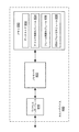
図1は、いくつかの実施形態による、ネットワークデバイス100のブロック図である。具体的には、ネットワークデバイス100は、媒体M1(たとえば、ワイヤレスチャネル)を介して別のデバイス(簡単にするために図示せず)と通信することができ得る。ネットワークデバイス100は、プロセッサ110と、メモリ120と、PHYデバイス130と、MACデバイス140とを含む。PHYデバイス130は、ワイヤレス媒体M1に結合されたトランシーバ135を含む。トランシーバ135はPHYデバイス130に含まれるものとして図1に示すが、トランシーバ135は独立型のデバイスまたは集積回路でもよい。メモリ120は、たとえば、EEPROMまたはフラッシュメモリを含む、任意の適切なメモリ素子またはデバイスでよい。プロセッサ110は、たとえば、メモリ120に記憶された1つまたは複数のソフトウェアプログラムのスクリプトまたは命令を実行することができる任意の適切なプロセッサでよい。
FIG. 1 is a block diagram of a network device 100 according to some embodiments. Specifically, network device 100 may be able to communicate with another device (not shown for simplicity) via medium M1 (eg, a wireless channel). The network device 100 includes a
PHYデバイス130およびMACデバイス140は各々、信号路160の組を介して、それぞれ、2つのデバイスの間で信号を送信するための媒体独立インターフェース(MII)150-1および150-2を含む。いくつかの実施形態では、MII150-1は、それぞれ、MACデバイス140との間でデータを送信および受信するための第1および第2のPHY側差動トランジスタ対(簡単にするために図示せず)を含むことができ、MII150-2は、それぞれ、PHYデバイス130との間でデータを送信および受信するための第1および第2のMAC側差動トランジスタ対(簡単にするために図示せず)を含むことができる。したがって、MII150-1は本明細書ではPHY側MIIと呼ぶことができ、MII150-2は本明細書ではMAC側MIIと呼ぶことができる。
PHY device 130 and MAC device 140 each include media independent interfaces (MII) 150-1 and 150-2 for transmitting signals between the two devices via a set of
MACデバイス140は、OSIMAC副層の機能を実装する任意のデバイスまたは集積回路でもよく、独立型のデバイスでもよく、またはネットワークデバイス100中に統合されてもよい。同様に、PHYデバイス130は、OSI物理層の機能を実装する任意のデバイスまたは集積回路でもよく、独立型のデバイスでもよく、またはネットワークデバイス100中に統合されてもよい。 The MAC device 140 may be any device or integrated circuit that implements the functions of the OSIMAC sublayer, may be a stand-alone device, or may be integrated into the network device 100. Similarly, PHY device 130 may be any device or integrated circuit that implements the functionality of the OSI physical layer, may be a stand-alone device, or may be integrated into network device 100.
データ送信動作の間、ネットワークデバイス100上のエンドユーザソフトウェアアプリケーションが媒体M1を介してデータを別のデバイスに送信するとき、プロセッサ110はOSIモデルの最上層に従ってデータを処理し、次いで、データをMACデバイス140を通じてPHYデバイス130に送信する。次いで、PHYデバイス130は、トランシーバ135を介してデータを媒体M1上に送信する。
During the data transmission operation, when an end user software application on the network device 100 transmits data to another device via the medium M1, the
図2は、いくつかの実施形態による、通信システム200を示す。システム200は、通信チャネル230を使用して互いに通信することができるホストデバイス210と3つのクライアントデバイス220(1)〜220(3)とを含むように示される。いくつかの実施形態では、通信チャネル230は、他の適切なワイヤレス通信プロトコルが使用され得るが、IEEE802.11規格により通信を容易にするワイヤレス(たとえば、WLANまたはWi-Fi)チャネルでよい。他の実施形態では、通信チャネル230は、ワイヤードリンク(たとえば、10GBASE-T Ethernet(登録商標)チャネル)でよい。さらに、簡単にするために、3つのクライアントデバイス220(1)〜220(3)が図2に示されるが、システム200は通信チャネル230を介してホストデバイス210に接続された任意の数のクライアントデバイス220を含み得る。
FIG. 2 shows a
コンピュータ、ラップトップ、タブレット、スマートフォン、または他の適切なコンピューティングまたは通信デバイスであり得るホストデバイス210は、プロセッサ211と、USBコントローラ212と、プロトコル適応層(PAL)ステーション管理エンティティ(SME)213とWLANインターフェース214とを含む。プロセッサ211は、USBコントローラ212に結合され、USBコントローラ212および/またはホストデバイス210の他の構成要素の動作を制御することができる。USBコントローラ212は、プロセッサ211とPAL SME213との間のUSB通信を容易にすることができる任意の適切なUSBコントローラでよい。少なくともいくつかの実施形態では、USBコントローラ212は、USB通信の符号化機能を提供するために物理符号化副層(PCS)回路(簡単にするために図示せず)を含み得るまたはそれに関連付けられ得る。Wi-Fiギガビットアライアンス(WGA)によって定義されたプロトコルにより動作することができるPAL SME213は、ワイヤレスチャネル230を介してホストデバイス210とクライアントデバイス220(1)〜220(3)との間のUSBデータの交換を可能にすることができる。PAL SME213に結合されるWLANインターフェース214は、ワイヤレスチャネル230を介してクライアントデバイス220(1)〜220(3)との間でデータを送信および受信するためにトランシーバを含むことができる。
The
クライアントデバイス220は、任意の適切なUSB周辺デバイス(たとえば、スピーカ、プリンタ、キーボード、マウスなど)でよい。簡単にするために図2には示していないが、クライアントデバイス220(1)〜220(3)の各々は、ワイヤレスチャネル230を介してUSBデータのワイヤレス交換を容易にするために、プロセッサと、USBコントローラと、PAL SMEと、WLANインターフェースとを含むことができる。
ホストデバイス210がクライアントデバイス220(1)〜220(3)にアイソクロナスUSBデータを正確な時点で(たとえば、互いに同時に)提供(render)させる場合、ホストUSBコントローラ212内のUSBフレームカウンタは、クライアントデバイス220(1)〜220(3)内のUSBフレームカウンタと同期させなければならない。たとえば、USBデータがクライアントデバイス(たとえば、スピーカとして働く)によって再生されるべきオーディオ情報を含む場合、複数のデバイス220(1)〜220(3)から同時にオーディオ情報の再生を可能にすることが望ましいことであり得る。したがって、クライアントデバイス220(1)〜220(3)をホストデバイス210と、および/または互いに、同期させることは望ましいことであり得る。
When
いくつかの実施形態では、ホストデバイス210とクライアントデバイス220(1)〜220(3)との間の通信は、双方向でよい。たとえば、場合によっては、クライアントデバイス220(1)〜220(3)の各々は、ホストデバイスとして働くことができ、ホストデバイス210は、クライアントデバイスとして働くことができる。より具体的には、ホストデバイス210およびクライアントデバイス220(1)〜220(3)は、ワイヤレス通信チャネル(たとえば、ワイヤレスチャネル230)を介してUSBフレームを送信し受信することが両方できる実質的に同様のコンピューティングデバイスであり得る。
In some embodiments, communication between the
図3は、クライアントデバイス220(1)〜220(3)をホストデバイス210と同期させることに伴う潜在的な問題を示す例示的なタイミング図300である。図2も参照すると、USBコントローラ212がプロセッサ211からデータを受信するとき、USBコントローラ212は、タイムスタンプ(Tp)をデータに添付し、後でクライアントデバイス220(1)〜220(3)に送信するためにデータをパケット中にカプセル化することができる。しかし、ホストデバイス210のMAC層とPHY層との間(たとえば、USBコントローラ212とWLANインターフェース214との間)には伝送遅延(Td)があり得る。データパケットが異なると一定でない可能性があるこの伝送遅延により、ホストデバイス210から送信されたデータパケットを受信し、処理しおよび/または表示するクライアントデバイス220(1)〜220(3)のうちの1つまたは複数に関連付けられたタイミングエラーが起こり得る。
FIG. 3 is an exemplary timing diagram 300 illustrating potential problems associated with synchronizing client devices 220 (1) -220 (3) with
このタイミング問題の1つの解決策は、ホストデバイス210内のデータパケットを解析し、オリジナルのタイムスタンプ(Tp)を抽出し、伝送遅延(Td)を計算し、次いで、オリジナルのタイムスタンプを更新して、伝送遅延を反映することを必要とし得る。ホストデバイス210内のディープパケットインスペクション(DPI)動作が関与し得るこのプロセスは、貴重な処理資源を消費し、時間のかかるものであり得る。さらに、多くの既存のホストデバイスは、USBコントローラ212から受信したUSBデータパケット/フレーム上のDPI動作を実行することができる回路またはソフトウェアモジュールを含まない可能性がある。
One solution to this timing problem is to analyze the data packet in the
いくつかの実施形態では、ホストデバイス210および/またはクライアントデバイス220(1)〜220(3)は、クライアントデバイス220(1)〜220(3)をホストデバイス210に同期させるためにIEEE802.11規格によって定義されたWLAN動作を利用することができる。より具体的には、ホストデバイス210は、クライアントデバイス220(1)〜220(3)のカウンタおよび/またはクロックが、確実にホストデバイス210のそれぞれのカウンタおよび/またはクロックと同期化される(および同期させたままである)ようにするために、IEEE802.11規格によって具現化される技法を採用することができる。たとえば、図4A〜図4Bは、いくつかの実施形態による、例示的なワイヤレスUSB同期動作を示すシーケンス図である。
In some embodiments, the
たとえば、図4Aを参照すると、ホストデバイス210は、クライアントデバイス220(1)〜220(3)への(および/または、からの)データの送信(および/または受信)を計時するのに使用され得る内部クロック信号(ClkH)を生成する。同様に、クライアントデバイス220(1)〜220(3)の各々は、ホストデバイス210からの(および/または、への)データの受信(および/または送信)を計時するのに使用され得る、対応するローカルクロック信号(Clk1〜Clk3)を生成することができる。いくつかの実施形態では、ホストデバイス210は、ローカルクロック信号Clk1〜Clk3をホストクロック信号ClkHと同期させるために、クロック同期(Clk_Sync)データをクライアントデバイス220(1)〜220(3)の各々に送信することができる。クライアントデバイス220(1)〜220(3)の各々は、次いで、そのローカルクロックをホストクロックClkHに整合させるために(たとえば、それぞれのタイミングオフセットをローカルクロックClk1〜Clk3に適用することにより)、Clk_Syncデータを使用することができる。
For example, referring to FIG. 4A, the
いくつかの実施形態では、クロック同期動作は、通信チャネル230に関連付けられた通信プロトコルによってすでに提供されている1つまたは複数のクロック同期機構または技法を使用して実行され得る。たとえば、ホストクロック信号ClkHおよびローカルクロック信号Clk1〜Clk3は、IEEE802.11ワイヤレスプロトコルによって定義されたタイミング同期機能(TSF)に基づいて生成され得る。あるいは、および/または、さらに、ホストクロック信号ClkHは、特定の適用例に所望される精度のレベルにより、他のクロック同期技法(たとえば、802.1AS、802.11v、および/または802.11mc規格によって定義されたクロック同期技法など)を使用して、ローカルクロック信号Clk1〜Clk3と同期され得る。
In some embodiments, the clock synchronization operation may be performed using one or more clock synchronization mechanisms or techniques already provided by the communication protocol associated with
TSFタイマは、マイクロ秒単位でインクリメントする(たとえば、「時を刻む」)係数264カウンタであり得、したがって、264=102,400マイクロ秒の最大カウント値を有する(他の適切なタイマ、クロック、および/またはカウンタを使用することができるが)。いくつかの実施形態では、ホストデバイス210は、そのTSFタイマ値を1つまたは複数のビーコンフレームにおいて、クライアントデバイス220(1)〜220(3)にブロードキャストすることができる。ビーコンフレームを受信すると、クライアントデバイス220(1)〜220(3)の各々は、それ自体のローカルTSFタイマを、受信したTSFタイマ値に設定することができる。これによって、クライアントデバイス220(1)〜220(3)のローカルTSFタイマ(たとえば、Clk1〜Clk3)が確実にホストデバイス210のTSFタイマ(たとえば、ClkH)と同期されるようになる。
The TSF timer can be a factor 2 64 counter that increments in microseconds (e.g., `` ticks '') and thus has a maximum count value of 2 64 = 102,400 microseconds (other suitable timers, clocks, And / or counters can be used). In some embodiments,
いくつかの実施形態では、Clk_Syncデータは、ホストデバイス210とクライアントデバイス220(1)〜220(3)との間でクロック同期を維持するために周期的にブロードキャストおよび/または送信され得る。たとえば、通信チャネル230がWi-Fiチャネルである場合、802.11仕様は、ホストデバイス210が周期的にビーコンフレームをクライアントデバイス220(1)〜220(3)にブロードキャストする、クロック同期機構を定義している。したがって、クライアントデバイス220(1)〜220(3)およびホストデバイス210は、ビーコン間隔(たとえば、ビーコンフレーム内に設けられる)によって離隔される一連のターゲットビーコン送信時間(TBTT)を確立することができる。クライアントデバイス220(1)〜220(3)は、次いで、新たなビーコンフレームを受信するたびにそれらのローカルTSFタイマをホストデバイス210のTSFタイマと再同期させることができる。
In some embodiments, Clk_Sync data may be broadcast and / or transmitted periodically to maintain clock synchronization between the
ローカルクロック信号Clk1〜Clk3がホストクロック信号ClkHと同期すると、ホストデバイス210は、通信チャネル230を介して、カプセル化されたUSBフレームをクライアントデバイス220(1)〜220(3)に送信し始めることができる。たとえば、USBフレームは、普通ならUSBケーブルを介してクライアントデバイス220(1)〜220(2)のうちの1つまたは複数に送信されるはずのUSBデータに対応することができる。代わりに、いくつかの実施形態では、USBフレームは、ワイヤレス通信プロトコルに基づいて、通信チャネル230を介して送信されるべき1つまたは複数のデータパケット内にカプセル化され(たとえば、に書き込まれ、および/または、によって運ばれ)得る。クライアントデバイス220(1)〜220(3)は、オリジナルのUSBフレームを取り戻すために受信したデータパケットのカプセル開放を行うことができる。いくつかの実施形態では、クライアントデバイス220(1)〜220(3)の各々は、ホストデバイス210から受信したUSBフレームごとにローカルフレームカウンタ(たとえば、Cnt1〜Cnt3)を更新することができる。
When the local clock signals Clk 1 -Clk 3 are synchronized with the host clock signal Clk H , the
たとえば、図4Bを参照すると、ホストデバイス210は、ホストデバイス210のフレームカウンタCntHをクライアントデバイス220(1)〜220(3)のローカルフレームカウンタCnt1〜3と同期させるために、それぞれ、カウント値に関連付けられたフレームカウント値(F_Count)および媒体時間(M_Time)を識別する情報をクライアントデバイス220(1)〜220(3)に送信することができる。フレームカウンタCntHは、ホストデバイス210によって送信されたUSBフレームの数を示すことができる。たとえば、ホストデバイス210は、クライアントデバイス220(1)〜220(3)に送信されたUSBフレームごとにフレームカウンタCntHを更新することができる。
For example, referring to FIG. 4B, the
F_Count値は、任意の所与の時間にホストデバイス210によって送信されたUSBフレームの総数(たとえば、ホストフレームカウンタCntHに基づく)を示すことができる。より具体的には、M_Time値は、F_Count値が決定されたおよび/または発信データパケットおよび/またはUSBフレーム内に埋め込まれた特定の時間(たとえば、ホストクロック信号ClkHに基づく)を指定することができる。いくつかの実施形態では、M_Time値は、各データパケットおよび/またはホストデバイス210によって送信されたフレーム内に埋め込まれた送信タイムスタンプ(たとえば、802.11仕様によって定義された)に対応することができる。いくつかの実施形態では、F_CountおよびM_Time値は、実質的に同じ時間で符号化することができ、したがって、互いに「対にする」ことができる。たとえば、F_CountおよびM_Time値は、1つまたは複数のUSBフレーム内にカプセル化され得、他のカプセル化されたUSBデータが提供され得る。あるいは、F_CountおよびM_Time値は、USBデータとは別個に送信され得る(たとえば、独立した管理フレームの一部として)。
The F_Count value may indicate the total number of USB frames transmitted by the
ローカルフレームカウンタCnt1〜Cnt3の各々は、それぞれ、F_Count値、M_Time値、および対応するローカルクロック信号Clk1〜Clk3に基づいてホストフレームカウンタCntHと同期され得る。たとえば、フレームカウント同期動作は、以下の式に基づいて任意のクライアントデバイス220に対して実行され得る。
Each of the local frame counters Cnt 1 -Cnt 3 may be synchronized with the host frame counter Cnt H based on the F_Count value, the M_Time value, and the corresponding local clock signals Clk 1 -Clk 3 , respectively. For example, a frame count synchronization operation may be performed for any

したがって、ローカルクロック信号Clk1〜Clk3の各々をホストクロック信号ClkHと同期させた後(たとえば、図4Aに関して上に説明したように)、ホストデバイス210によるF_Count値の符号化とクライアントデバイス220(1)〜220(3)のうちの1つによるその受信との間で経過した時間の量は、F_Count値が受信される時間(たとえば、ローカルクロック信号Clk1〜Clk3に基づいて)を計り、M_Time値を減算することによって決定され得る。この経過時間の間、ホストデバイス210によって送信された可能性がある追加のUSBフレームの数は、経過時間をホストデバイス210の伝送速度(たとえば、クロックサイクル別に送信され得るUSBフレームの総数)で乗算することによって決定され得る。結果は、次いで、ホストカウンタCntHの現在のカウント値を決定するためにF_Count値に追加され得る。
Thus, after synchronizing each of the local clock signals Clk 1 -Clk 3 with the host clock signal Clk H (eg, as described above with respect to FIG. 4A), the encoding of the F_Count value by the
クライアントデバイス220(1)〜220(3)は、次いで、続いて受信したUSBフレームに基づいてそれらのそれぞれのローカルカウンタCnt1〜3を更新することができる。しかし、個々のクライアントデバイス220(1)〜220(3)がUSBフレームを受信する速度は異なり得ることに留意されたい。たとえば、ホストデバイス210によるデータの送信の遅延、通信チャネル230に沿った伝搬遅延、および/またはマルチパス状態により、クライアントデバイス220(1)〜220(3)の各々は、異なる時間にUSBフレームを受信することができる。したがって、任意の所与の時間において、クライアントデバイス220(1)〜220(3)のうちの1つによってバッファリングされたUSBフレームの数は、別のクライアントデバイスによってバッファリングされたUSBフレームの数とは異なり得る。たとえば、特定の時間Tにおいて、ホストカウンタCntHは、Nのカウント値を有することができ、ローカルカウンタCnt1は、Nのカウント値を記憶することができ、ローカルカウンタCnt2は、N-1のカウント値を記憶することができ、ローカルカウンタCnt3は、N-2のカウント値を記憶することができる。いくつかの実施形態では、ホストデバイス210は、ホストカウンタCntHとローカルカウンタCnt1〜Cnt3の各々との間の同期を維持するために、新たなF_CountおよびM_Time値をクライアントデバイス220(1)〜220(3)に周期的に送信することができる。これによって、ローカルフレームカウンタCnt1〜Cnt3の各々は、クライアントデバイス220(1)〜220(3)のそれぞれの1つによって受信されおよび/またはバッファリングされたUSBフレーム数だけでなく、ホストデバイス210によって送信されたフレームの総数のカウントを維持することが可能になる。
Client device 220 (1) -220 (3) may then be updated each local counter Cnt 1 ~ 3 of them on the basis of the subsequently USB frames received. However, it should be noted that the rate at which individual client devices 220 (1) -220 (3) receive USB frames can vary. For example, each of the client devices 220 (1) -220 (3) has a USB frame at a different time due to delays in sending data by the
いくつかの実施形態では、ホストデバイス210は、特定のフレームカウントに基づいて、受信したUSBフレームを処理し、および/または提供することを開始する命令とともに、処理要求メッセージをクライアントデバイス220(1)〜220(3)のうちの1つまたは複数に送信することができる。たとえば、クライアントデバイス220(1)〜220(3)の各々は、ホストデバイス210から受信したUSBフレームをバッファリングする内部記憶素子を含むことができる。クライアントデバイス220(1)〜220(3)は、ホストデバイス210によって、バッファリングされたUSBフレームの処理または提供を開始するように命令されるまで、USBフレームをバッファリングすることを継続することができる。いくつかの実施形態では、処理要求メッセージは、ローカルフレームカウンタが特定のフレームカウント閾値に達した後、クライアントデバイス220(1)〜220(3)にUSBフレームの処理を開始するように命令することができる。しかし、上に説明したように、ローカルフレームカウンタCnt1〜Cnt3は、ホストカウンタCntHに対してドリフトすることがある。それにもかかわらず、クライアントデバイス220(1)〜220(3)の各々が実質的に同じ時間に(たとえば、クライアントデバイス220(1)〜220(3)の各々が同じオーディオ信号を再生するように構成されたスピーカである場合のように)、記憶されたUSBフレームの処理または提供を開始することは、望ましいことであり得る。したがって、ローカルフレームカウンタCnt1〜Cnt3の各々をホストカウンタCntHと同期させることによって、複数のクライアントデバイス220(1)〜220(3)が同時にUSBの処理を開始することが可能になり得る。
In some embodiments, the
通信チャネル230用に設けられた既存のクロックプロトコルを活用することによって、システム200は、ディープパケットインスペクションを必要とせずにホストデバイス210とクライアントデバイス220(1)〜220(3)との間で同期させたUSBフレームカウントを効率的におよび正確に維持することができる。その上、本実施形態によれば、クライアントデバイス220(1)〜220(3)の各々は、クライアントデバイス220(1)〜220(3)が異なる時間においてそのような値を受信しても、F_CountおよびM_Time値を使用して、ホストデバイス210の現在のフレームカウントを決定することができる。
By leveraging the existing clock protocol provided for
図5は、いくつかの実施形態による、USBクライアントデバイスを動作させる例示的な方法500を示す例示的なフローチャートである。たとえば、方法500は、図2および図4A〜図4Bに関して上に説明したクライアントデバイス220のうちのいずれかによって実装され得る。具体的には、クライアントデバイス220は、ネットワークを介して1つまたは複数のUSBフレームをホストデバイス210から受信することができる(501)。いくつかの実施形態では、1つまたは複数のUSBフレームは、ネットワークに関連付けられた通信プロトコルに基づいて、1つまたは複数のデータパケット内にカプセル化され得る。クライアントデバイス220は、1つまたは複数のUSBフレームを取り戻すために、受信したデータパケットのカプセル開放を行うことができる。さらに、いくつかの実施形態では、クライアントデバイス220は、受信したUSBフレームをデータバッファに記憶することができる。
FIG. 5 is an exemplary flowchart illustrating an
クライアントデバイス220は、そのローカルクロック信号をホストデバイスのクロック信号とさらに同期させる(502)。具体的には、クライアントデバイス220は、通信プロトコルのクロック同期機構に基づいて、そのローカルクロック信号をホストクロック信号と同期させることができる。たとえば、ホストデバイス210は、そのローカルクロック信号を調整するためにクライアントデバイス220によって使用され得るクロック同期(Clk_Sync)データを周期的に送信またはブロードキャストすることができる。802.11ワイヤレスネットワークでは、クロック同期データは、1つまたは複数のビーコンフレームにおいて、ホストデバイス210によってブロードキャストされたTSF値に対応することができる。クライアントデバイス220は、次いで、ホストデバイス210のTSF値に一致するように(たとえば、図4Aに関して上に説明するように)それ自体のTSF値を(必要に応じ)調整することができる。
クライアントデバイス220は、次いで、ホストデバイス210によって送信されたUSBフレームの数を決定する(503)。具体的には、クライアントデバイス220は、同期させたローカルクロック信号に基づいて、ホストデバイス210によって送信されたUSBフレームの数を決定することができる。たとえば、クライアントデバイス220は、ホストデバイス210から受信したUSBフレームごとにローカルフレームカウンタを更新することができる。しかし、上に説明したように、クライアントデバイス220によって受信されたUSBフレームの数は、ホストデバイス210によって送信されたUSBフレームの数に必ずしも一致するとは限らない可能性がある(たとえば、ドリフトおよび/または中止したデータパケットにより)。したがって、いくつかの実施形態では、ローカルフレームカウンタは、ホストデバイス210によって送信された同期データに基づいて、ホストデバイス210内のUSBフレームカウンタを追跡することができる。同期データは、たとえば、フレームカウント(F_Count)値および媒体時間(M_Time)値を含むことができる。より具体的には、F_Count値は、M_Time値によって指定された時間にホストデバイス210によって送信されたUSBフレームの数を示すことができる。クライアントデバイス220は、次いで、M_Time値によって示された時間以来送信された追加のUSBフレームの数を決定するために、同期させたローカルクロック信号を使用することができる(たとえば、図4Bに関して上に説明したように)。いくつかの実施形態では、クライアントデバイス220は、そのローカルフレームカウンタをホストデバイス210のフレームカウンタと周期的に再同期させることができる。
最後に、クライアントデバイス220は、ホストデバイス210によって送信されたUSBフレームの数に基づいて、受信したUSBフレームを処理することができる(504)。たとえば、ホストデバイス210は、ローカルフレームカウンタが特定のフレームカウント閾値に達すると、クライアントデバイス220に、受信したUSBフレームの処理および/または提供を開始するように命令することができる。ローカルフレームカウンタは、ホストフレームカウンタと同期され得るので、クライアントデバイス220は、ホストデバイス210によって示されたときにいつでもUSBフレームの処理を開始することができる。これにより、複数のクライアントデバイス220が、そのときに各クライアントデバイス220によって実際に受信されたUSBフレームの数にかかわらず、実質的に同時にUSBフレームの処理を開始することが可能になり得る。
Finally, the
図6は、いくつかの実施形態による、USBホストデバイスを動作させる例示的な方法600を示す例示的なフローチャートである。たとえば、方法600は、図2および図4A〜4Bに関して上に説明したホストデバイス210によって実装され得る。具体的には、ネットワーク上のホストデバイス210は、ネットワークに関連付けられた通信プロトコルに基づいて、USBフレームをデータパケット内にカプセル化することができる(601)。上に説明したように、USBフレームは、普通であればUSBケーブルを介して1つまたは複数のクライアントデバイス220に送信されるはずのUSBデータに対応することができる。ホストデバイス210は、たとえば、対応するUSBデータを特定のタイプの通信チャネルを介して送信されるべき1つまたは複数のデータパケット内に埋め込むことによって、USBフレームをカプセル化することができる。
FIG. 6 is an exemplary flowchart illustrating an
ホストデバイス210は、次いで、ネットワークを介して、カプセル化されたUSBフレームを含むデータパケットを1つまたは複数のクライアントデバイス220に送信することができる(602)。たとえば、ネットワークは、IEEE802.11規格によって定義されたWi-Fiネットワークに対応することができる。したがって、ホストデバイス210は、1つまたは複数の802.11ワイヤレスプロトコルに基づいて、データパケットを1つまたは複数のクライアントデバイス220に送信することができる。いくつかの実施形態では、ホストデバイス210は、同時に、データパケットを複数のクライアントデバイス220に送信することができる。さらに、いくつかの実施形態では、ホストデバイス210は、1つまたは複数のクライアントデバイス220に送信されたUSBフレームの数の経過を追跡するために、USBフレームカウンタを含むことができる。たとえば、ホストデバイス210は、送信されたUSBフレームごとに、そのUSBフレームカウンタを更新することができる。
The
ホストデバイス210は、各クライアントデバイス220がUSBフレームを処理することを可能にするために、同期データの組を1つまたは複数のクライアントデバイス220にさらに送信することができる(603)。同期データは、たとえば、クロック同期(Clk_Sync)データ、フレームカウント(F_Count)値、および/または媒体時間(M_Time)値を含むことができる。より具体的には、Clk_Syncデータは、ホストデバイス210のクロック信号を1つまたは複数のクライアントデバイス220のローカルクロック信号と同期させるのに使用され得る(たとえば、図4Aに関して上に説明したように)。いくつかの実施形態では、Clk_Syncデータは、ワイヤレス通信プロトコルに関連付けられたクロック同期機構によって提供され得る。F_CountおよびM_Time値は、ホストデバイス210のUSBフレームカウンタを1つまたは複数のクライアントデバイス220のローカルフレームカウンタと同期させるのに使用され得る(たとえば、図4Bに関して上に説明したように)。上に説明したように、F_Count値は、M_Time値によって指定された時間にホストデバイス210によって送信されたUSBフレームの数を示すことができる。いくつかの実施形態では、ホストデバイス210は、1つまたは複数のクライアントデバイス220の各々との同期を維持するために、更新された同期データを周期的に送信することができる。
The
図7は、いくつかの実施形態による、ワイヤレスUSB同期動作700を示す例示的なフローチャートである。たとえば、図4A〜図4Bを参照すると、ホストデバイス210は、まず、ワイヤレス通信チャネル230を介して、クロック同期データをクライアントデバイスに送信する(たとえば、クライアントデバイス220(1))(701)。いくつかの実施形態では、クロック同期データは、ビーコンフレーム内に設けられたTSFタイマ値に対応することができる。クライアントデバイス220(1)は、ワイヤレス通信チャネル230を介してクロック同期データを受信し(702)、通信チャネル230に関連付けられたクロック同期機構を使用して、そのローカルクロック信号Clk1をホストクロック信号ClkHと同期させる(704)。たとえば、クライアントデバイス220(1)は、ホストデバイスのTSFタイマ値を使用して、そのローカルクロック信号Clk1と同期させることができる(たとえば、図4Aに関して上に説明したように)。
FIG. 7 is an exemplary flowchart illustrating a wireless
ホストデバイス210は、ワイヤレス通信チャネル230を介して送信するためにUSBフレームをカプセル化する(703)。たとえば、図2を参照すると、PAL SME213は、Wi-Fiプロトコルにより、Wi-Fiチャネルを介して送信されるべきUSBフレーム(たとえば、USBコントローラ212を介して受信した)をカプセル化することができる。いくつかの実施形態では、カプセル化は、WGAプロトコルにより実行され得る。ホストデバイス210は、現在のフレームカウントおよび媒体時間値をカプセル化されたUSBフレーム内に埋め込む(705)。たとえば、F_Count値は、ホストフレームカウンタCntHから記録され得、対応するM_Time値は、ホストクロック信号ClkHから記録され得る。いくつかの実施形態では、F_CountおよびM_Time値は、互いに対にされ、実質的に同時に記録される。最後に、ホストデバイス210は、ワイヤレス通信チャネル230を介して、カプセル化されたUSBフレームをクライアントデバイス220(1)に送信する(707)。
クライアントデバイス220(1)は、ワイヤレス通信チャネルを介して、カプセル化されたUSBフレームを受信し(706)、それとともに提供されたF_CountおよびM_Time値を解析する(708)。いくつかの実施形態では、クライアントデバイス220(1)は、USBデータのカプセル開放を行うことなく、受信したデータパケットからF_CountおよびM_Time値を解析することができる。クライアントデバイス220(1)は、次いで、受信したF_CountおよびM_Time値ならびに同期させたローカルクロック信号Clk1に基づいて、そのローカルフレームカウンタCnt1をホストフレームカウンタCntHと同期させる(710)。たとえば、クライアントデバイス220(1)は、式1に基づいて、そのローカルフレームカウンタCnt1を更新することができる(たとえば、図4Bに関して上に説明したように)。 Client device 220 (1) receives the encapsulated USB frame over the wireless communication channel (706) and analyzes the F_Count and M_Time values provided therewith (708). In some embodiments, the client device 220 (1) can analyze the F_Count and M_Time values from the received data packet without decapsulating the USB data. The client device 220 (1) then synchronizes its local frame counter Cnt 1 with the host frame counter Cnt H based on the received F_Count and M_Time values and the synchronized local clock signal Clk 1 (710). For example, client device 220 (1) may update its local frame counter Cnt 1 based on Equation 1 (eg, as described above with respect to FIG. 4B).
いくつかの実施形態では、ホストデバイス210は、続いて特定のフレームカウントから始まるUSBフレームを処理させおよび/または提供させる命令を発することができる(709)。たとえば、ホストデバイス210によって指定されたフレームカウントは、ホストフレームカウンタCntHのカウント値に対応することができる。そのような命令を受信すると、クライアントデバイス220(1)は、次に、そのローカルフレームカウンタCnt1に基づいて、バッファリングされたUSBフレームを処理しおよび/または提供する(712)。具体的には、ローカルフレームカウンタCnt1がホストフレームカウンタCntHと同期しているので、クライアントデバイス220(1)は、クライアントデバイス220(1)によって実際に受信したおよび/またはバッファリングされたUSBフレームの数にかかわらず、所望の時間にそのバッファリングされたUSBデータの処理を開始することができる。
In some embodiments, the
簡単にするためだけに、前述の同期動作700が、クライアントデバイス220(1)に関して説明されている。しかし、動作700は、ホストデバイス210とクライアントデバイス220(1)〜220(3)のうちのいずれかとの間で実質的に同様のやり方で実行され得る。さらに、同期動作700により、ワイヤレスチャネル230を介して複数のクライアントデバイス220(1)〜220(3)に送信されたUSBデータパケットは、正確な時間に(たとえば、同期して)再生されおよび/または提供される(たとえば、クライアントデバイス220(1)〜220(3)に関連付けられたスピーカから出力される)ことが確実になり得る。
For simplicity only, the
図8は、いくつかの実施形態による、USB使用可能クライアントデバイス800のブロック図である。クライアントデバイス800は、ワイヤレスインターフェース810と、USBインターフェース820と、プロセッサ830と、メモリ840とを含む。ワイヤレスインターフェース810は、プロセッサ830に結合され、ワイヤレス通信チャネルを介して、データ信号を受信および/または送信するのに使用され得る。たとえば、ワイヤレス通信チャネルは、IEEE802.11ワイヤレスチャネルに対応することができる。USBインターフェース820は、プロセッサ830にも結合され、クライアントデバイス800へのおよび/またはからUSBデータを通信するのに使用され得る(たとえば、USBケーブルを介して)。いくつかの実施形態では、ワイヤレスインターフェース810は、データパケット内にカプセル化された、普通であればUSBインターフェース820を介して受信されるはずのUSBフレームを受信することができる。
FIG. 8 is a block diagram of a USB enabled client device 800 according to some embodiments. Client device 800 includes a wireless interface 810, a USB interface 820, a
メモリ840は、デバイス800によって処理および/または再生されるべきUSBフレームをバッファリングするのに使用され得るデータストア842を含むことができる。たとえば、ワイヤレスインターフェース810を介して受信したUSBフレームは、データストア842に記憶され得る。さらに、メモリ840は、以下のソフトウェアモジュールを記憶することができる、非一時的コンピュータ可読記憶媒体(たとえば、EPROM、EEPROM、フラッシュメモリ、ハードドライブなどの1つまたは複数の不揮発性メモリ素子)も含むことができる。
ローカルクロック信号をホストデバイスのクロック信号と同期させるためのクロック同期モジュール844、
ローカルフレームカウンタをホストデバイスのUSBフレームカウンタと同期させるためのフレーム同期モジュール846、および
ローカルフレームカウンタのフレームカウント値に基づいて、受信したUSBフレームを処理するためのUSB処理モジュール848。
各ソフトウェアモジュールは、プロセッサ830によって実行されたとき、デバイス800に、対応する機能を実行させることができる命令を含むことができる。したがって、メモリ840の非一時的コンピュータ可読記憶媒体は、図5および図7に関して説明した動作の全部または一部を実行するための命令を含むことができる。
Memory 840 can include a data store 842 that can be used to buffer USB frames to be processed and / or played by device 800. For example, a USB frame received via the wireless interface 810 can be stored in the data store 842. In addition, memory 840 also includes non-transitory computer readable storage media (e.g., one or more non-volatile memory elements such as EPROM, EEPROM, flash memory, hard drive, etc.) that can store the following software modules: be able to.
A clock synchronization module 844 for synchronizing the local clock signal with the clock signal of the host device,
A frame synchronization module 846 for synchronizing the local frame counter with the USB frame counter of the host device, and a USB processing module 848 for processing the received USB frame based on the frame count value of the local frame counter.
Each software module may include instructions that, when executed by
メモリ840に結合されたプロセッサ830は、クライアントデバイス800に(たとえば、メモリ840内)に記憶された1つまたは複数のソフトウェアプログラムの命令のスクリプトを実行することができる任意の適切なプロセッサでよい。たとえば、プロセッサ830は、クロック同期モジュール844、フレーム同期モジュール846、および/またはUSB処理モジュール848を実行することができる。
The
クロック同期モジュール844は、ローカルクロック信号をホストデバイスのクロック信号と同期させるためにプロセッサ830によって実行され得る。たとえば、クライアントデバイス800は、ワイヤレスインターフェース810を介してホストデバイスからクロック同期(Clk_Sync)データを受信することができる。いくつかの実施形態では、Clk_Syncデータは、ホストデバイスによって周期的にブロードキャストされる(たとえば、ビーコンフレームにおいて)TSF値に対応することができる。クロック同期モジュール844は、プロセッサ830によって実行されたとき、それ自体のローカルTSFタイマを、受信したTSF値に設定することによって、そのローカルクロック信号をホストクロック信号と同期させることができる(たとえば、図4Aに関して上に説明したように)。
The clock synchronization module 844 may be executed by the
フレーム同期モジュール846は、ローカルフレームカウンタをホストデバイスのUSBフレームカウンタと同期させるためにプロセッサ830によって実行され得る。たとえば、クライアントデバイス800は、フレームカウント(F_Count)値および媒体時間(M_Time)値をホストデバイスからワイヤレスインターフェース810を介してさらに受信することができる。上に説明したように、F_Count値は、M_Time値によって示された特定の時間においてホストデバイスによって送信されたUSBフレームの数を示すことができる。フレーム同期モジュール846は、プロセッサ830によって実行されたとき、F_CountおよびM_Time値、ローカルクロック信号ならびにホストデバイスの伝送速度に基づいて、そのローカルフレームカウンタをホストフレームカウンタと同期させることができる(たとえば、図4Bに関して上に説明したように)。いくつかの実施形態では、プロセッサ830は、フレーム同期モジュール846を実行する際に、ホストデバイスから受信したUSBフレームごとに、ローカルフレームカウンタを連続して更新する(たとえば、インクリメントする)ことができる。
Frame synchronization module 846 may be executed by
USB処理モジュール848は、ローカルフレームカウンタのフレームカウント値に基づいて、受信したUSBフレームを処理するために、プロセッサ830によって実行され得る。たとえば、USB処理モジュール848は、プロセッサ830によって実行されたとき、ローカルフレームカウンタが特定のフレームカウント閾値に達すると、データストア842に記憶されたUSBフレームの処理を開始することができる。いくつかの実施形態では、フレームカウント閾値は、ホストデバイスによって指定され得る(たとえば、クライアントデバイス800に処理要求メッセージを送信することによって)。ローカルフレームカウンタがホストフレームカウンタと同期され得るので、プロセッサ830は、USB処理モジュール848を実行する際に、ホストデバイスによって示されるときはいつでもUSBフレームの処理を開始することができる。
The USB processing module 848 may be executed by the
図9はいくつかの実施形態による、USB使用可能ホストデバイス900のブロック図である。ホストデバイス900は、ワイヤレスインターフェース910と、プロセッサ920と、メモリ930とを含む。ワイヤレスインターフェース910は、プロセッサ920に結合され、ワイヤレス通信チャネルを介して、データ信号を送信および/または受信するのに使用され得る。たとえば、ワイヤレス通信チャネルは、IEEE802.11ワイヤレスチャネルに対応することができる。いくつかの実施形態では、ワイヤレスインターフェース910は、データパケット内にカプセル化されたUSBフレームをワイヤレスで送信することができる。
FIG. 9 is a block diagram of a USB enabled
メモリ930は、カプセル化されるべき、および1つまたは複数のクライアントデバイスに送信されるべきUSBフレームをバッファリングするのに使用され得るデータストア932を含むことができる。さらに、メモリ930は、以下のソフトウェアモジュールを記憶することができる非一時的コンピュータ可読記憶媒体(たとえば、EPROM、EEPROM、フラッシュメモリ、ハードドライブなどの1つまたは複数の不揮発性メモリ素子)も含むことができる。
ホストクロック信号をクライアントデバイスのローカルクロック信号と同期させるためのクロック同期モジュール934、
ホストフレームカウンタをクライアントデバイスのローカルフレームカウンタと同期させるためのフレーム同期モジュール936、および
ワイヤレスインターフェース910を介して送信するためにUSBフレームをデータパケット中に符号化するためのUSBカプセル化モジュール938。
各ソフトウェアモジュールは、プロセッサ920によって実行されたとき、デバイス900に、対応する機能を実行させることができる命令を含むことができる。したがって、メモリ930の非一時的コンピュータ可読記憶媒体は、図6および図7に関して説明した動作の全部または一部を実行するための命令を含むことができる。
Memory 930 can include a data store 932 that can be used to buffer USB frames to be encapsulated and to be sent to one or more client devices. In addition, the memory 930 also includes a non-transitory computer readable storage medium (e.g., one or more non-volatile memory elements such as EPROM, EEPROM, flash memory, hard drive, etc.) that can store the following software modules: Can do.
A clock synchronization module 934 for synchronizing the host clock signal with the local clock signal of the client device,
A frame synchronization module 936 for synchronizing the host frame counter with the local frame counter of the client device, and a USB encapsulation module 938 for encoding the USB frame into a data packet for transmission via the wireless interface 910.
Each software module may include instructions that, when executed by the
メモリ930に結合されたプロセッサ920は、ホストデバイス900(たとえば、メモリ930内)に記憶された1つまたは複数のソフトウェアプログラムの命令のスクリプトを実行することができる任意の適切なプロセッサでよい。たとえば、プロセッサ920は、クロック同期モジュール934、フレーム同期モジュール936、および/またはUSB処理モジュール938を実行することができる。
The
クロック同期モジュール934は、ホストクロック信号をクライアントデバイスのローカルクロック信号と同期させるために、プロセッサ920によって実行され得る。たとえば、クロック同期モジュール934は、プロセッサ920によって実行されたとき、ワイヤレスインターフェース910を介して、1つまたは複数のクライアントデバイスに送信されるべきクロック同期(Clk_Sync)データを生成することができる。いくつかの実施形態では、Clk_Syncデータは、ホストデバイス900のTSFタイマ(たとえば、IEEE802.11仕様によって定義された)に基づいてTSF値に対応することができる。1つまたは複数のクライアントデバイスの各々は、次いで、Clk_Syncデータを使用して、そのローカルクロック信号をホストクロック信号と同期させることができる(たとえば、図4Aに関して上に説明したように)。いくつかの実施形態では、プロセッサ920は、クロック同期モジュール934を実行する際に、クロック_Syncデータを周期的に(たとえば、ビーコンフレーム内で)複数のクライアントデバイスに同時にブロードキャストすることができる。
The clock synchronization module 934 may be executed by the
フレーム同期モジュール936は、ホストフレームカウンタをクライアントデバイスのローカルフレームカウンタと同期させるためにプロセッサ920によって実行され得る。たとえば、フレーム同期モジュール936は、プロセッサ920によって実行されたとき、ワイヤレスインターフェース910を介して1つまたは複数のクライアントデバイスに送信されるべきフレームカウント(F_Count)値および媒体時間(M_Time)値を生成することができる。いくつかの実施形態では、F_Count値は、M_Time値によって示される特定の時間におけるホストフレームカウンタのカウント値に対応することができる。1つまたは複数のクライアントデバイスの各々は、次いで、F_CountおよびM_Time値、ローカルクロック信号、ならびにホストデバイスの伝送速度に基づいて、そのローカルフレームカウンタをホストフレームカウンタと同期させることができる(たとえば、図4Bに関して上に説明したように)。いくつかの実施形態では、プロセッサ920は、フレーム同期モジュール936を実行する際に、1つまたは複数のクライアントデバイスに送信されたUSBフレームごとに、ホストフレームカウンタを連続的に更新する(たとえば、インクリメントする)ことができる。
A frame synchronization module 936 may be executed by the
USB処理モジュール938は、ワイヤレスインターフェース910を介して送信するためのUSBフレームをデータパケット中に符号化するためにプロセッサ920によって実行され得る。たとえば、USB処理モジュール938は、プロセッサ920によって実行されたとき、対応するUSBデータをワイヤレスで送信されるべき1つまたは複数のデータパケットに書き込むことによってUSBフレームをカプセル化することができる。いくつかの実施形態では、カプセル化は、WGAプロトコルにより実行され得る。さらに、いくつかの実施形態では、プロセッサ920は、USB処理モジュール938を実行する際に、USBフレームとともに1つまたは複数のクライアントデバイスに送信されるべき処理要求メッセージを生成することができる。上に説明したように、処理要求メッセージは、対応するUSBフレームを処理するための命令を含むことができる(たとえば、特定のUSBフレームカウントに基づいて)。
USB processing module 938 may be executed by
いくつかの実施形態では、クライアントデバイス800は、ホストデバイス900の1つまたは複数の機能を実行することができ、逆も同様であることに留意されたい。たとえば、クライアントデバイス800は、ホストデバイス900の1つまたは複数のソフトウェアモジュール(たとえば、934〜938)を含むことができる。同様に、ホストデバイス900は、クライアントデバイス800のうちの1つまたは複数のソフトウェアモジュール(たとえば、844〜848)を含むことができる。
It should be noted that in some embodiments, the client device 800 can perform one or more functions of the
上記の明細書において、本実施形態について、その特定の例示的な実施形態を参照しながら説明してきた。しかし、添付の特許請求の範囲に記載された本開示のより広い範囲から逸脱することなく、様々な修正および変更をそれに加えることができることは明らかであろう。したがって、本明細書および図面は、限定的ではなく例示的であると見なされるべきである。たとえば、図5〜図7のフローチャートに示す方法ステップは他の適切な順序で実行することができ、複数のステップは組み合わせて単一のステップにすることができ、および/またはいくつかのステップは省略することができる。 In the foregoing specification, the embodiments have been described with reference to specific exemplary embodiments thereof. However, it will be apparent that various modifications and changes may be made thereto without departing from the broader scope of the disclosure as set forth in the appended claims. The specification and drawings are accordingly to be regarded as illustrative rather than restrictive. For example, the method steps shown in the flowcharts of FIGS. 5-7 can be performed in other suitable orders, multiple steps can be combined into a single step, and / or some steps can be Can be omitted.
100 ネットワークデバイス
110 プロセッサ
120 メモリ
130 PHYデバイス
135 トランシーバ
140 MACデバイス
150-1 媒体独立インターフェース(MII)
150-2 媒体独立インターフェース(MII)
160 信号路
200 通信システム
210 ホストデバイス
211 プロセッサ
212 USBコントローラ
213 プロトコル適応層(PAL)ステーション管理エンティティ
214 WLANインターフェース
220(1) クライアントデバイス
220(2) クライアントデバイス
220(3) クライアントデバイス
230 通信チャネル
300 タイミング図
500 例示的な方法
600 例示的な方法
700 ワイヤレス同期動作
800 USB使用可能クライアントデバイス
810 ワイヤレスインターフェース
820 USBインターフェース
830 プロセッサ
840 メモリ
842 データストア
844 クロック同期モジュール
846 フレーム同期モジュール
848 USB処理モジュール
900 USB使用可能ホストデバイス
910 ワイヤレスインターフェース
920 プロセッサ
930 メモリ
932 データストア
934 クロック同期モジュール
936 フレーム同期モジュール
938 USBカプセル化モジュール
M1 ワイヤレス媒体
100 network devices
110 processor
120 memory
130 PHY devices
135 transceiver
140 MAC devices
150-1 Media Independent Interface (MII)
150-2 Media Independent Interface (MII)
160 signal path
200 Communication system
210 Host device
211 processor
212 USB controller
213 Protocol Adaptation Layer (PAL) station management entity
214 WLAN interface
220 (1) Client device
220 (2) Client device
220 (3) Client device
230 Communication channel
300 Timing diagram
500 Exemplary Method
600 Exemplary Method
700 wireless sync operation
800 USB enabled client device
810 wireless interface
820 USB interface
830 processor
840 memory
842 Data Store
844 clock synchronization module
846 Frame synchronization module
848 USB processing module
900 USB-enabled host device
910 wireless interface
920 processor
930 memory
932 Data Store
934 Clock synchronization module
936 frame synchronization module
938 USB encapsulation module
M1 wireless media
Claims (16)
前記ネットワークを介してホストデバイスから1つまたは複数のUSBフレームを受信するステップであって、前記1つまたは複数のUSBフレームが、ネットワークに関連付けられた通信プロトコルに基づいて1つまたは複数のデータパケット内にカプセル化される、受信するステップと、
前記通信プロトコルのクロック同期機構を使用して、前記USBデバイスのローカルクロック信号を前記ホストデバイスのクロック信号と同期させるステップと、
少なくとも部分的に、前記同期させたローカルクロック信号に基づいて、前記ホストデバイスによって送信されたUSBフレームの数を決定するステップと、
少なくとも部分的に、前記ホストデバイスによって送信されたUSBフレームの数に基づいて、前記1つまたは複数のUSBフレームを処理するステップと、を含む方法。 A method of operating a universal serial bus (USB) device on a network,
Receiving one or more USB frames from a host device via the network, wherein the one or more USB frames are one or more data packets based on a communication protocol associated with the network; Receiving, encapsulated in, and
Using the clock synchronization mechanism of the communication protocol to synchronize the local clock signal of the USB device with the clock signal of the host device;
Determining the number of USB frames transmitted by the host device based at least in part on the synchronized local clock signal;
Processing the one or more USB frames based at least in part on the number of USB frames transmitted by the host device.
前記ホストデバイスから1つまたは複数のビーコンフレームを受信するステップであって、前記ビーコンフレームのうちの少なくとも1つが、タイミング同期機能(TSF)値を含む、受信するステップと、
前記受信したTSF値に基づいて前記ローカルクロック信号を調整するステップとを含む、請求項1に記載の方法。 Synchronizing the local clock signal comprises:
Receiving one or more beacon frames from the host device, wherein at least one of the beacon frames includes a timing synchronization function (TSF) value; and
Adjusting the local clock signal based on the received TSF value.
少なくとも部分的に、前記データバッファに記憶された前記USBフレームの数に基づいて、ローカルフレームカウンタを更新するステップと、
前記ローカルフレームカウンタに基づいて、前記ホストデバイスによって送信されたUSBフレームの前記数を決定するステップとを含む、請求項4に記載の方法。 Determining the number of USB frames transmitted by the host device;
Updating a local frame counter based at least in part on the number of USB frames stored in the data buffer;
And determining the number of USB frames transmitted by the host device based on the local frame counter.
前記ホストデバイスから媒体時間値を受信するステップであって、前記媒体時間値が、前記フレームカウント値が記録される時間を示す、受信するステップとをさらに含む、請求項5に記載の方法。 Receiving a frame count value from the host device, wherein the frame count value indicates the number of USB frames transmitted by the host device; and
6. The method of claim 5, further comprising receiving a media time value from the host device, wherein the media time value indicates a time at which the frame count value is recorded.
少なくとも部分的に、前記ローカルクロック信号、前記フレームカウント値、および前記媒体時間値に基づいて、前記ローカルフレームカウンタを前記ホストデバイス内のUSBフレームカウンタと同期させるステップをさらに含む、請求項6に記載の方法。 Determining the number of USB frames transmitted by the host device;
7. The method of claim 6, further comprising synchronizing the local frame counter with a USB frame counter in the host device based at least in part on the local clock signal, the frame count value, and the media time value. the method of.
前記ローカルフレームカウンタが第1の閾値に達したとき、前記1つまたは複数のUSBフレームを処理するステップを含む、請求項8に記載の方法。 Processing the one or more USB frames;
9. The method of claim 8, comprising processing the one or more USB frames when the local frame counter reaches a first threshold.
前記ネットワークに関連付けられた通信プロトコルに基づいて、1つまたは複数のユニバーサルシリアルバス(USB)フレームを1つまたは複数のデータパケット内にカプセル化するステップと、
前記ネットワークを介して、前記1つまたは複数のカプセル化されたUSBフレームを含む、前記1つまたは複数のデータパケットを1つまたは複数のクライアントデバイスに送信するステップと、
前記1つまたは複数のクライアントデバイスが前記1つまたは複数のUSBフレームを処理することを可能にする同期データの組を前記1つまたは複数のクライアントデバイスに送信するステップであって、前記同期データの組が、前記1つまたは複数のクライアントデバイスがそれぞれのローカルクロック信号を前記コンピューティングデバイスのクロック信号と同期させることを可能にするクロック同期データを含む、送信するステップとを含む、方法。 A method of operating a computing device on a network, comprising:
Encapsulating one or more universal serial bus (USB) frames in one or more data packets based on a communication protocol associated with the network;
Transmitting the one or more data packets including the one or more encapsulated USB frames to one or more client devices via the network;
Transmitting to the one or more client devices a set of synchronization data that enables the one or more client devices to process the one or more USB frames, the method comprising: Transmitting a set comprising clock synchronization data that enables the one or more client devices to synchronize their local clock signal with the clock signal of the computing device.
1つまたは複数のビーコンフレーム内の前記クロック同期データをブロードキャストするステップであって、前記クロック同期データが、タイミング同期機能(TSF)値を含む、ブロードキャストするステップを含む、請求項10に記載の方法。 Transmitting the clock synchronization data comprises:
11. The method of claim 10 , comprising broadcasting the clock synchronization data in one or more beacon frames, wherein the clock synchronization data includes a timing synchronization function (TSF) value. .
前記通信プロトコルのクロック同期機構を使用して、前記USBデバイスのローカルクロック信号を前記ホストデバイスのクロック信号と同期させるための手段と、
少なくとも部分的に、前記同期させたローカルクロック信号に基づいて、前記ホストデバイスによって送信されたUSBフレームの数を決定するための手段と、
少なくとも部分的に、前記ホストデバイスによって送信されたUSBフレームの前記数に基づいて、前記1つまたは複数のUSBフレームを処理するための手段とを備える、ユニバーサルシリアルバス(USB)デバイス。 Means for receiving one or more USB frames from a host device over a network, wherein the one or more USB frames are based on a communication protocol associated with the network Means for receiving, encapsulated in a data packet of
Means for synchronizing a local clock signal of the USB device with a clock signal of the host device using a clock synchronization mechanism of the communication protocol;
Means for determining the number of USB frames transmitted by the host device based at least in part on the synchronized local clock signal;
A universal serial bus (USB) device comprising means for processing the one or more USB frames based at least in part on the number of USB frames transmitted by the host device.
ネットワークに関連付けられた通信プロトコルに基づいて、1つまたは複数のユニバーサルシリアルバス(USB)フレームを1つまたは複数のデータパケット内にカプセル化するための手段と、
ネットワークを介して、1つまたは複数のクライアントデバイスに、前記1つまたは複数のカプセル化されたUSBフレームを含む、前記1つまたは複数のデータパケットを送信するための手段と、
前記ワイヤレスネットワークを介して、前記1つまたは複数のクライアントデバイスに、前記1つまたは複数のクライアントデバイスが前記1つまたは複数のUSBフレームを処理することを可能にする同期データの組を送信するための手段であって、前記同期データの組が、前記1つまたは複数のクライアントデバイスがそれぞれのローカルクロック信号を前記コンピューティングデバイスのクロック信号と同期させることを可能にするクロック同期データを含む、送信するための手段とを備える、コンピューティングデバイス。 A computing device,
Means for encapsulating one or more Universal Serial Bus (USB) frames in one or more data packets based on a communication protocol associated with the network;
Means for transmitting the one or more data packets comprising the one or more encapsulated USB frames to one or more client devices over a network;
To send a set of synchronization data over the wireless network to the one or more client devices that allow the one or more client devices to process the one or more USB frames. Means for transmitting, wherein the set of synchronization data includes clock synchronization data that enables the one or more client devices to synchronize their local clock signal with the clock signal of the computing device. A computing device comprising: means for:
Applications Claiming Priority (5)
| Application Number | Priority Date | Filing Date | Title |
|---|---|---|---|
| US201361823805P | 2013-05-15 | 2013-05-15 | |
| US61/823,805 | 2013-05-15 | ||
| US14/270,124 | 2014-05-05 | ||
| US14/270,124 US9830298B2 (en) | 2013-05-15 | 2014-05-05 | Media time based USB frame counter synchronization for Wi-Fi serial bus |
| PCT/US2014/037035 WO2014186179A1 (en) | 2013-05-15 | 2014-05-06 | Media time based usb frame counter synchronization for wi-fi serial bus |
Publications (3)
| Publication Number | Publication Date |
|---|---|
| JP2016526325A JP2016526325A (en) | 2016-09-01 |
| JP2016526325A5 JP2016526325A5 (en) | 2017-06-08 |
| JP6333963B2 true JP6333963B2 (en) | 2018-05-30 |
Family
ID=51896736
Family Applications (1)
| Application Number | Title | Priority Date | Filing Date |
|---|---|---|---|
| JP2016513982A Active JP6333963B2 (en) | 2013-05-15 | 2014-05-06 | Medium time based USB frame counter synchronization for Wi-Fi serial bus |
Country Status (9)
| Country | Link |
|---|---|
| US (1) | US9830298B2 (en) |
| EP (1) | EP2997485B1 (en) |
| JP (1) | JP6333963B2 (en) |
| KR (1) | KR102249244B1 (en) |
| CN (1) | CN105247500B (en) |
| AR (1) | AR099254A1 (en) |
| ES (1) | ES2638212T3 (en) |
| TW (1) | TWI552558B (en) |
| WO (1) | WO2014186179A1 (en) |
Families Citing this family (15)
| Publication number | Priority date | Publication date | Assignee | Title |
|---|---|---|---|---|
| US20150026505A1 (en) * | 2013-07-17 | 2015-01-22 | Kabushiki Kaisha Toshiba | Storage device, storage system, and background processing execution method |
| US9723610B2 (en) * | 2015-04-07 | 2017-08-01 | Qualcomm Incorporated | Multi-layer timing synchronization framework |
| JP6534913B2 (en) * | 2015-11-06 | 2019-06-26 | 日立オートモティブシステムズ株式会社 | Information processing apparatus and fraudulent message detection method |
| US10095653B2 (en) * | 2016-04-02 | 2018-10-09 | Intel Corporation | Apparatuses, systems, and methods for accurately measuring packet propagation delays through USB retimers |
| SG11201900499SA (en) * | 2016-07-29 | 2019-02-27 | Razer Asia Pacific Pte Ltd | Interface devices, methods for controlling an interface device, and computer-readable media |
| US10915490B2 (en) | 2018-02-15 | 2021-02-09 | Qualcomm Incorporated | Audio streams over peripheral component interconnect (PCI) express (PCIE) links |
| KR20190119400A (en) * | 2018-04-12 | 2019-10-22 | (주)에프씨아이 | A method for efficiently estimating a reception time of a beacon signal and a receiving device there for |
| DE102018206934A1 (en) | 2018-05-04 | 2019-11-07 | Continental Automotive Gmbh | Gateway for data communication in a vehicle |
| US10896106B2 (en) | 2018-05-10 | 2021-01-19 | Teradyne, Inc. | Bus synchronization system that aggregates status |
| TWI772574B (en) * | 2018-12-07 | 2022-08-01 | 新唐科技股份有限公司 | Universal serial bus device and operation method thereof |
| CN111464252B (en) * | 2019-01-22 | 2023-01-06 | 华为技术有限公司 | Communication method and optical module |
| US11245985B2 (en) | 2019-03-27 | 2022-02-08 | Microsoft Technology Licensing, Llc | Architecture for USB-synchronized array of speakers |
| US20220100685A1 (en) * | 2019-06-18 | 2022-03-31 | Razer (Asia-Pacific) Pte. Ltd. | Method and apparatus for optimizing input latency in a wireless human interface device system |
| CN110768739B (en) * | 2019-09-27 | 2021-04-20 | 上海鹰钛智能科技有限公司 | Synchronous serial control system and method |
| CN114780469A (en) * | 2022-06-24 | 2022-07-22 | 浙江地芯引力科技有限公司 | Clock frequency calibration device, data chip and clock frequency calibration method |
Family Cites Families (37)
| Publication number | Priority date | Publication date | Assignee | Title |
|---|---|---|---|---|
| US5943328A (en) * | 1996-08-13 | 1999-08-24 | Lucent Technologies Inc. | Frame counter for synchronized communication |
| JP3045985B2 (en) * | 1997-08-07 | 2000-05-29 | インターナショナル・ビジネス・マシーンズ・コーポレイション | Connection establishment method, communication method, state change transmission method, state change execution method, wireless device, wireless device, and computer |
| US6389029B1 (en) * | 1998-11-10 | 2002-05-14 | Nortel Networks Limited | Local area network incorporating universal serial bus protocol |
| US6978412B1 (en) * | 1999-08-16 | 2005-12-20 | Advanced Micro Devices, Inc. | Method and apparatus for adaptive frame tracking |
| US6678747B2 (en) | 1999-08-23 | 2004-01-13 | Honeywell International Inc. | Scalable data collection and computing apparatus |
| US6934752B1 (en) * | 2000-03-23 | 2005-08-23 | Sharewave, Inc. | Quality of service extensions for multimedia applications in wireless computer networks |
| US7734758B1 (en) | 2000-07-19 | 2010-06-08 | Cisco Technology, Inc. | USB encapsulation for network transmission |
| US7065036B1 (en) * | 2001-03-19 | 2006-06-20 | Cisco Systems Wireless Networking (Australia) Pty Limited | Method and apparatus to reduce latency in a data network wireless radio receiver |
| US6898652B2 (en) * | 2001-08-22 | 2005-05-24 | General Atomics | Wireless device attachment and detachment system, apparatus and method |
| CN1326057C (en) | 2001-09-28 | 2007-07-11 | 皇家飞利浦电子股份有限公司 | Bus system and bus interface for connection to a bus |
| EP1901178B1 (en) | 2002-07-17 | 2010-02-24 | Chronologic Pty Ltd | Synchronized multichannel universal serial bus |
| US7284081B2 (en) | 2004-01-27 | 2007-10-16 | Atmel Corporation | Method and system for routing data between USB ports |
| US7668243B2 (en) * | 2004-05-18 | 2010-02-23 | Texas Instruments Incorporated | Audio and video clock synchronization in a wireless network |
| US7149839B2 (en) * | 2004-12-03 | 2006-12-12 | Microsoft Corporation | Wireless USB hardware scheduling |
| US8560753B1 (en) * | 2005-03-30 | 2013-10-15 | Teradici Corporation | Method and apparatus for remote input/output in a computer system |
| US7406476B1 (en) * | 2005-04-04 | 2008-07-29 | Apple Inc. | Updating a data structure |
| US7539889B2 (en) * | 2005-12-30 | 2009-05-26 | Avega Systems Pty Ltd | Media data synchronization in a wireless network |
| JP2007194791A (en) * | 2006-01-18 | 2007-08-02 | Kawasaki Microelectronics Kk | Data transfer device |
| US8069294B2 (en) * | 2006-03-30 | 2011-11-29 | Intel Corporation | Power-optimized frame synchronization for multiple USB controllers with non-uniform frame rates |
| US20070294456A1 (en) * | 2006-06-16 | 2007-12-20 | Hong Kong Applied Science And Technology Research Institute Co., Ltd. | Data communication interface and communication devices incorporating same |
| JP4835345B2 (en) * | 2006-09-19 | 2011-12-14 | ソニー株式会社 | Wireless communication apparatus, wireless communication method, wireless communication system, and computer program |
| US7697522B2 (en) * | 2006-11-20 | 2010-04-13 | Broadcom Corporation | Systems and methods for aggregation of packets for transmission through a communications network |
| JP4935345B2 (en) * | 2006-12-25 | 2012-05-23 | ソニー株式会社 | Content reproduction system, reproduction apparatus, reproduction control method, and program |
| AU2008251024B2 (en) * | 2007-05-15 | 2013-01-24 | Chronologic Pty Ltd | USB based synchronization and timing system |
| KR101141276B1 (en) * | 2007-06-04 | 2012-05-04 | 삼성전자주식회사 | Communication method of host apparatus capable of connecting with device using WUSB and system including the host apparatus and the device |
| JP2009003677A (en) * | 2007-06-21 | 2009-01-08 | Nec Electronics Corp | Usb host, usb slave, wireless communication system, and data transfer method |
| CN102089932B (en) * | 2008-07-10 | 2015-04-22 | 马维尔国际贸易有限公司 | Systems and methods for reducing power consumption in wireless devices |
| WO2010007578A1 (en) * | 2008-07-17 | 2010-01-21 | Jungo Ltd. | Cableless usb connectivity over ieee 802.11 networks |
| US8503596B2 (en) | 2008-10-02 | 2013-08-06 | Aliphcom | Wireless clock regeneration and synchronization |
| US20140075567A1 (en) * | 2009-01-28 | 2014-03-13 | Headwater Partners I Llc | Service Processor Configurations for Enhancing or Augmenting System Software of a Mobile Communications Device |
| JP5418003B2 (en) * | 2009-06-12 | 2014-02-19 | ソニー株式会社 | Information processing apparatus, synchronization correction method, and computer program |
| US8493992B2 (en) * | 2010-02-04 | 2013-07-23 | Texas Instruments Incorporated | Interrelated WiFi and USB protocols and other application framework processes, circuits and systems |
| GB201116521D0 (en) * | 2011-09-23 | 2011-11-09 | Imagination Tech Ltd | Method and apparatus for time synchronisation in wireless networks |
| EP2608444B1 (en) * | 2011-12-19 | 2014-10-22 | GN Netcom A/S | Method and system for synchronizing isochronous usb audio data to a rf communication device clock |
| CN103918231B (en) * | 2013-03-15 | 2016-10-05 | 华为技术有限公司 | A kind of apparatus and method of Optical Channel Data Unit-k operation exchange |
| US9532043B2 (en) * | 2013-08-02 | 2016-12-27 | Blackberry Limited | Wireless transmission of real-time media |
| US9412332B2 (en) * | 2013-12-20 | 2016-08-09 | Blackberry Limited | Method for wirelessly transmitting content from a source device to a sink device |
-
2014
- 2014-05-05 US US14/270,124 patent/US9830298B2/en active Active
- 2014-05-06 WO PCT/US2014/037035 patent/WO2014186179A1/en active Application Filing
- 2014-05-06 ES ES14730016.4T patent/ES2638212T3/en active Active
- 2014-05-06 CN CN201480027932.3A patent/CN105247500B/en active Active
- 2014-05-06 JP JP2016513982A patent/JP6333963B2/en active Active
- 2014-05-06 KR KR1020157035312A patent/KR102249244B1/en active IP Right Grant
- 2014-05-06 EP EP14730016.4A patent/EP2997485B1/en active Active
- 2014-05-14 AR ARP140101947A patent/AR099254A1/en not_active Application Discontinuation
- 2014-05-14 TW TW103117039A patent/TWI552558B/en active
Also Published As
| Publication number | Publication date |
|---|---|
| KR102249244B1 (en) | 2021-05-06 |
| AR099254A1 (en) | 2016-07-13 |
| KR20160008602A (en) | 2016-01-22 |
| WO2014186179A1 (en) | 2014-11-20 |
| US9830298B2 (en) | 2017-11-28 |
| TWI552558B (en) | 2016-10-01 |
| CN105247500B (en) | 2018-04-27 |
| TW201448539A (en) | 2014-12-16 |
| CN105247500A (en) | 2016-01-13 |
| US20140344490A1 (en) | 2014-11-20 |
| EP2997485B1 (en) | 2017-06-14 |
| JP2016526325A (en) | 2016-09-01 |
| ES2638212T3 (en) | 2017-10-19 |
| EP2997485A1 (en) | 2016-03-23 |
Similar Documents
| Publication | Publication Date | Title |
|---|---|---|
| JP6333963B2 (en) | Medium time based USB frame counter synchronization for Wi-Fi serial bus | |
| EP3367733B1 (en) | Method, device, and system for synchronizing clocks of processors | |
| US8023976B2 (en) | Method and system for accurate clock synchronization for communication networks | |
| US10129839B2 (en) | Techniques for synchronizing timing of wireless streaming transmissions to multiple sink devices | |
| US11588568B2 (en) | Packet processing method and network device | |
| WO2015196685A1 (en) | Clock synchronization method and apparatus | |
| CN110401505A (en) | A kind of wireless network accurate time synchronization method | |
| EP3098987B1 (en) | Time slot synchronization training method for optical burst transport network node, node device and network | |
| JP2008527894A (en) | Method for synchronizing receiver clock to transmitter clock in less than 100 nanoseconds | |
| US20130336237A1 (en) | Adapter, base band processing unit and base station system | |
| WO2010102565A1 (en) | Method, apparatus and system for time synchronization | |
| US11064452B2 (en) | Wireless apparatus, processing method for a wireless apparatus, and program | |
| EP2774291B1 (en) | Services, systems and methods for precisely estimating a delay within a network |
Legal Events
| Date | Code | Title | Description |
|---|---|---|---|
| A521 | Request for written amendment filed |
Free format text: JAPANESE INTERMEDIATE CODE: A523 Effective date: 20170419 |
|
| A621 | Written request for application examination |
Free format text: JAPANESE INTERMEDIATE CODE: A621 Effective date: 20170419 |
|
| A977 | Report on retrieval |
Free format text: JAPANESE INTERMEDIATE CODE: A971007 Effective date: 20180326 |
|
| TRDD | Decision of grant or rejection written | ||
| A01 | Written decision to grant a patent or to grant a registration (utility model) |
Free format text: JAPANESE INTERMEDIATE CODE: A01 Effective date: 20180402 |
|
| A61 | First payment of annual fees (during grant procedure) |
Free format text: JAPANESE INTERMEDIATE CODE: A61 Effective date: 20180425 |
|
| R150 | Certificate of patent or registration of utility model |
Ref document number: 6333963 Country of ref document: JP Free format text: JAPANESE INTERMEDIATE CODE: R150 |
|
| R250 | Receipt of annual fees |
Free format text: JAPANESE INTERMEDIATE CODE: R250 |
|
| R250 | Receipt of annual fees |
Free format text: JAPANESE INTERMEDIATE CODE: R250 |
|
| R250 | Receipt of annual fees |
Free format text: JAPANESE INTERMEDIATE CODE: R250 |