JP6333196B2 - Method for generating 3D image of area and system for generating 3D image of area - Google Patents
Method for generating 3D image of area and system for generating 3D image of area Download PDFInfo
- Publication number
- JP6333196B2 JP6333196B2 JP2015034006A JP2015034006A JP6333196B2 JP 6333196 B2 JP6333196 B2 JP 6333196B2 JP 2015034006 A JP2015034006 A JP 2015034006A JP 2015034006 A JP2015034006 A JP 2015034006A JP 6333196 B2 JP6333196 B2 JP 6333196B2
- Authority
- JP
- Japan
- Prior art keywords
- image
- sar
- area
- data set
- generating
- Prior art date
- Legal status (The legal status is an assumption and is not a legal conclusion. Google has not performed a legal analysis and makes no representation as to the accuracy of the status listed.)
- Active
Links
Images


Classifications
-
- G—PHYSICS
- G01—MEASURING; TESTING
- G01S—RADIO DIRECTION-FINDING; RADIO NAVIGATION; DETERMINING DISTANCE OR VELOCITY BY USE OF RADIO WAVES; LOCATING OR PRESENCE-DETECTING BY USE OF THE REFLECTION OR RERADIATION OF RADIO WAVES; ANALOGOUS ARRANGEMENTS USING OTHER WAVES
- G01S13/00—Systems using the reflection or reradiation of radio waves, e.g. radar systems; Analogous systems using reflection or reradiation of waves whose nature or wavelength is irrelevant or unspecified
- G01S13/88—Radar or analogous systems specially adapted for specific applications
- G01S13/89—Radar or analogous systems specially adapted for specific applications for mapping or imaging
- G01S13/90—Radar or analogous systems specially adapted for specific applications for mapping or imaging using synthetic aperture techniques, e.g. synthetic aperture radar [SAR] techniques
- G01S13/904—SAR modes
-
- H—ELECTRICITY
- H03—ELECTRONIC CIRCUITRY
- H03M—CODING; DECODING; CODE CONVERSION IN GENERAL
- H03M7/00—Conversion of a code where information is represented by a given sequence or number of digits to a code where the same, similar or subset of information is represented by a different sequence or number of digits
- H03M7/30—Compression; Expansion; Suppression of unnecessary data, e.g. redundancy reduction
- H03M7/3059—Digital compression and data reduction techniques where the original information is represented by a subset or similar information, e.g. lossy compression
- H03M7/3062—Compressive sampling or sensing
-
- G—PHYSICS
- G01—MEASURING; TESTING
- G01S—RADIO DIRECTION-FINDING; RADIO NAVIGATION; DETERMINING DISTANCE OR VELOCITY BY USE OF RADIO WAVES; LOCATING OR PRESENCE-DETECTING BY USE OF THE REFLECTION OR RERADIATION OF RADIO WAVES; ANALOGOUS ARRANGEMENTS USING OTHER WAVES
- G01S13/00—Systems using the reflection or reradiation of radio waves, e.g. radar systems; Analogous systems using reflection or reradiation of waves whose nature or wavelength is irrelevant or unspecified
- G01S13/02—Systems using reflection of radio waves, e.g. primary radar systems; Analogous systems
- G01S13/06—Systems determining position data of a target
- G01S13/08—Systems for measuring distance only
- G01S13/10—Systems for measuring distance only using transmission of interrupted, pulse modulated waves
- G01S13/22—Systems for measuring distance only using transmission of interrupted, pulse modulated waves using irregular pulse repetition frequency
-
- G—PHYSICS
- G01—MEASURING; TESTING
- G01S—RADIO DIRECTION-FINDING; RADIO NAVIGATION; DETERMINING DISTANCE OR VELOCITY BY USE OF RADIO WAVES; LOCATING OR PRESENCE-DETECTING BY USE OF THE REFLECTION OR RERADIATION OF RADIO WAVES; ANALOGOUS ARRANGEMENTS USING OTHER WAVES
- G01S13/00—Systems using the reflection or reradiation of radio waves, e.g. radar systems; Analogous systems using reflection or reradiation of waves whose nature or wavelength is irrelevant or unspecified
- G01S13/02—Systems using reflection of radio waves, e.g. primary radar systems; Analogous systems
- G01S13/06—Systems determining position data of a target
- G01S13/42—Simultaneous measurement of distance and other co-ordinates
Description
本発明は、包括的には合成レーダシステムに関し、より詳細には、3次元断層イメージングシステムに関する。 The present invention relates generally to synthetic radar systems, and more particularly to three-dimensional tomographic imaging systems.
合成開口レーダ(SAR)システムは、移動プラットフォームに配置されたアンテナの動きを利用して大きな仮想開口部を合成し、結果として高分解能イメージングをもたらす。異なる空間ロケーションにおける各仮想配列は、ベースラインを形成する。単一パス(単一ベースライン)SARシステムは、対象エリアの2次元(2D)距離方位反射率を高度分解能なしでイメージングすることが可能である。しかしながら、エリアの3次元(3D)地形特徴等の3D構造は保持されない。 Synthetic Aperture Radar (SAR) systems synthesize large virtual apertures using the motion of antennas located on a mobile platform, resulting in high resolution imaging. Each virtual array at a different spatial location forms a baseline. A single pass (single baseline) SAR system is capable of imaging two-dimensional (2D) range-azimuth reflectivity of an area of interest without high resolution. However, 3D structures such as 3D (3D) terrain features of the area are not preserved.
2D画像は、本質的には3D反射率空間の2D距離方位イメージング平面への投影である。この投影によって、いくつかのアーチファクトが生じる場合がある。例えば、レイオーバアーチファクトでは、異なる仰角を有するいくつかの地形パッチが同じ距離方位分解能セルにマッピングされる。非特許文献1を参照されたい。 A 2D image is essentially a projection of a 3D reflectivity space onto a 2D distance orientation imaging plane. This projection may cause some artifacts. For example, in layover artifacts, several terrain patches with different elevation angles are mapped to the same range-azimuth resolution cell. See Non-Patent Document 1.
シャドーイングアーチファクトでは、ある特定のエリアが、照射経路に別の構造があることに起因してSARシステムにとって不可視である。これらのアーチファクトは、たとえ干渉SAR技法を用いたとしても、単一パスで解像することができない。 In shadowing artifacts, certain areas are invisible to the SAR system due to different structures in the illumination path. These artifacts cannot be resolved in a single pass, even using interferometric SAR techniques.
TerraSAR−XおよびCOSMO−Skymedの人工衛星の打ち上げによって、3Dイメージングが可能になった。これらのシステムは、異なるベースラインおよび時間において収集された複数のパスからの複素SAR画像のスタックを利用し、散乱オブジェクトの3Dロケーションおよび動き情報を捕捉する3D画像を形成する。非特許文献2を参照されたい。
The launch of TerraSAR-X and COSMO-Skymed satellites has enabled 3D imaging. These systems utilize a stack of complex SAR images from multiple passes collected at different baselines and times to form a 3D image that captures the 3D location and motion information of the scattered object. See Non-Patent
単一レーダプラットフォームに搭載されたアンテナ101の複数のベースライン配列を用いて、3D高度、距離および方位空間に関して3D画像を生成する従来の3D SARシステムが図1に示される。この図は、異なる高度の点散乱体102を示す。
A conventional 3D SAR system that generates 3D images in terms of 3D altitude, distance and orientation space using multiple baseline arrays of
図2は、図1のシステムの従来の3Dイメージングプロセスを示す。データ201は、各ベースライン(1,...,N)101で取得される。2D SARイメージング210は、各データ201に独立して適用され、2D画像(I1,I2,...,IN)215を構成する。画像は、登録および整列され(220)、その後、3D画像再構成(230)によって3D画像240が取得される。
FIG. 2 shows a conventional 3D imaging process of the system of FIG.
3D画像は、散乱体が同じ距離方位ロケーションに存在する場合でも、追加の高度次元を用いて、高度に沿って複数の散乱体を分けることができる。しかしながら、3D画像は、いくつかのトレードオフを要する。第1に、プラットフォームは、複数のベースラインにおいて画像を取得するために、対象エリアにわたっていくつかのパスを行う必要がある。これにより、データ収集は、時間および非常に高い費用を要するものとなる。第2に、高度分解能は、仰角開口の小ささに起因して、距離および方位の分解能に比べて大幅に劣る。この仰角開口は、現代のSARセンサにおいて、例えば直径約500メートルの緊密な(tight)軌道チューブ(orbital tube)として知られる。 A 3D image can separate multiple scatterers along an altitude using additional altitude dimensions even when the scatterers are at the same distance orientation location. However, 3D images require some tradeoffs. First, the platform needs to make several passes across the area of interest in order to acquire images at multiple baselines. This makes data collection time consuming and very expensive. Second, the altitude resolution is significantly inferior to the distance and azimuth resolution due to the small elevation aperture. This elevation opening is known in modern SAR sensors as, for example, a tight orbital tube having a diameter of about 500 meters.
高度分解能は、圧縮センシング(CS)に基づく手法を用いて改善することができる。非特許文献3を参照されたい。このCS手法は、複数のベースラインと、単一SARプラットフォームの単一PRFとを用いる。この方法では、2D距離方位画像は、ベースラインごとに再構成される。そして、圧縮センシングに基づく方法が高度分解能を改善するために用いられる。この方法は、2D距離方位ピクセルごとのスパース性しか考慮していない。 High resolution can be improved using approaches based on compressed sensing (CS). See Non-Patent Document 3. This CS approach uses multiple baselines and a single PRF with a single SAR platform. In this method, the 2D distance orientation image is reconstructed for each baseline. A method based on compressed sensing is then used to improve the altitude resolution. This method only considers sparseness per 2D distance orientation pixel.
本発明の実施形態は、合成開口レーダ(SAR)イメージングのための圧縮センシング(CS)に基づく方法を提供する。本方法は、取得する必要のある生データの総量を減らし、高度の分解能を上げる。特に、本実施形態は、複数の平行なベースラインにおいて収集されたSARデータを方位高度平面において用いる。高度の分解能は、従来の3D SARシステムのものと比べて実質的に高い。その増加量は約4倍である。 Embodiments of the present invention provide a method based on compressed sensing (CS) for synthetic aperture radar (SAR) imaging. The method reduces the total amount of raw data that needs to be acquired and increases the high resolution. In particular, this embodiment uses SAR data collected at a plurality of parallel baselines in the azimuth altitude plane. The high resolution is substantially higher than that of conventional 3D SAR systems. The increase is about 4 times.
各ベースラインの高度は、利用可能な高度空間においてランダムに分布する。さらに、各ベースラインにおけるアンテナ配列は、一定パルス繰り返し周波数(PRF)またはパルス繰り返しレート(PRR)を用いる。これらは、時間単位(例えば、秒)ごとのパルス数である。各ベースラインのPRFは異なる。したがって、複数のベースラインによって、データ取得に柔軟性がもたらされる。例えば、データは、単一SARプラットフォームの複数のパスにおいて取得することもできるし、様々なSARプラットフォームから取得することもできる。全てのベースラインが空間領域に整列および配置されるとすると、CSに基づく反復イメージング方法を用いることで、マルチベースラインデータを用いて高分解能3D反射率マップを生成することができる。
The altitude of each baseline is randomly distributed in the available altitude space. Furthermore, the antenna arrangement at each baseline uses a constant pulse repetition frequency (PRF) or pulse repetition rate (PRR). These are the number of pulses per time unit (eg, seconds). Each baseline PRF is different. Thus, multiple baselines provide flexibility in data acquisition. For example, data can be obtained in multiple passes of a single SAR platform or from various SAR platforms. Given that all baselines are aligned and arranged in the spatial domain, a
実施形態はいくつかの利点を提供する。特に、CSに基づく方法を用いることで、非常に少ない数のベースラインのみを用いて3D反射率を生成することができる。これにより、データ収集に要する時間および費用が削減される。第2に、異なるPRFのデータを一緒に処理することで、単一SARプラットフォームの複数のパスからのみならず、複数のレーダプラットフォームからのデータも融合することが可能になる。複数のプラットフォームによって、単一SARプラットフォームに比べてはるかに大きな仮想仰角開口を形成することが可能になる。その結果、非常に高い高度分解能、例えば、従来の3D SARシステムの4倍の高度分解能が得られる。 Embodiments provide several advantages. In particular, by using a CS-based method, 3D reflectivity can be generated using only a very small number of baselines. This reduces the time and cost required for data collection. Second, by processing data from different PRFs together, it is possible to fuse data from multiple radar platforms as well as from multiple paths of a single SAR platform. Multiple platforms allow a much larger virtual elevation opening to be created compared to a single SAR platform. The result is very high altitude resolution, for example, 4 times higher resolution than conventional 3D SAR systems.
本方法は、3D断層SARイメージングおよびCSに基づくSARイメージングに関するが、新たな寄与をなすものである。実施形態は、従来技術とは異なり、マルチベースラインデータにおいて複数の異なるPRFを可能にする。これにより、データソースが単一SARプラットフォームから複数のプラットフォームに拡張され、はるかに大きな仰角開口が可能になる。さらに、実施形態は、取得された生データに対し直接動作する、新たなCSに基づく反復イメージング方法を提供する。 The method relates to 3D tomographic SAR imaging and CS-based SAR imaging, but makes a new contribution. Embodiments allow for multiple different PRFs in multi-baseline data, unlike the prior art. This extends the data source from a single SAR platform to multiple platforms, allowing a much larger elevation opening. Furthermore, embodiments provide a new CS-based iterative imaging method that operates directly on the acquired raw data.
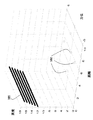
図3および図4に示すように、本発明の実施形態は、合成開口レーダ(SAR)3D画像を生成する方法を提供する。本方法は、複数のベースライン301および複数のパルス繰り返し周波数(PRF)においてデータセットを取得する。複数のベースラインは、対象エリアにわたっていくつかのパスを行う単一プラットフォーム、または同じエリアにわたってパスする複数の異なるプラットフォームを用いて確立することができる。
As shown in FIGS. 3 and 4, embodiments of the present invention provide a method for generating a synthetic aperture radar (SAR) 3D image. The method acquires a data set at
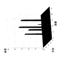
この説明において、点散乱体302とともに、3D空間に配置された3Dオブジェクトを考慮する。空間において高度方向に沿ってランダムに分布する、合計70本のベースラインを考慮する。これらのベースラインは、高度に沿って均一な間隔で置かれた281本の可能なベースラインから選択される。図3を参照されたい。ベースラインの合計本数は、従来の3D SARシステムにおけるものと比べて実質的に少ない。
In this description, a 3D object placed in 3D space is considered along with the
本シミュレーションにおいて、従来の3D SARシステムに必要とされるベースラインの全体本数の25%しか必要としない。その上で、高度分解能を約4倍に上げることができる。 In this simulation, only 25% of the total number of baselines required for a conventional 3D SAR system is required. In addition, the altitude resolution can be increased about four times.
各ベースラインにおいて、SAR生データセットは一定PRFで取得される。一方、異なるベースラインに関して、対応するPRFは、他のPRFと異なるようにランダムに選択される。特に、全てのベースラインからのデータセットは、ベースPRFから始まって、ランダム整数値によってダウンサンプリングされる。つまり、各PRFは、ベースPRFの一部であり、ダウンサンプリングレートは、セット{2,3,4,5}からランダムに選択される。全てのデータセットは完全に整列しているとみなす。 At each baseline, the SAR raw data set is acquired at a constant PRF. On the other hand, for different baselines, the corresponding PRF is randomly selected to be different from other PRFs. In particular, the data sets from all baselines are downsampled by a random integer value starting from the base PRF. That is, each PRF is a part of the base PRF, and the downsampling rate is randomly selected from the set {2, 3, 4, 5}. All datasets are considered perfectly aligned.
2つの異なる手法を比較する。第1の従来手法は、それぞれが異なるPRFを有する70本のベースラインでの削減されたデータ収集と、従来のイメージング方法とを用いる。本発明に係る手法では、削減されたデータ収集と、本発明のCSに基づくイメージング手法とを用いる。従来の3Dイメージングにおいては、データをアップサンプリングし、欠落データをゼロで補うことによって、近距離レンジマイグレーションイメージング手順(near−field range migration imaging procedure)を用いる。この手順は、取得されたデータから高速のビーム形成結果を生成し、取得演算子の逆を実施する。 Compare two different approaches. The first conventional approach uses reduced baseline data collection at 70 baselines, each with a different PRF, and conventional imaging methods. The technique according to the present invention uses reduced data collection and the CS-based imaging technique of the present invention. In conventional 3D imaging, a near-field range migration imaging procedure is used by upsampling data and compensating for missing data with zeros. This procedure generates a fast beamforming result from the acquired data and performs the inverse of the acquisition operator.
CSに基づくイメージングにおいては、シーンのスパース性を利用する反復手順を用いて欠落データを補い、その後、高速マイグレーションイメージングを行う。 In imaging based on CS, missing data is compensated by using an iterative procedure using the sparsity of the scene, and then high-speed migration imaging is performed.
図4に示されるように、データセット401は、SARシステムのセット{1,...,N}から取得される。上述したように、データセットは、単一システムの複数のパスにおいて取得することができる(405)。ここで、この説明において、各パスは独立したデータセット、または異なるSARシステムによる複数のパス、または単一システムおよび独立システムの複数のパスの何らかの組合せを生成する。
As shown in FIG. 4, the
データセット401は、登録および整列され(410)、整列したデータセット415が生成される。整列の後、整列した複数のベースライン、複数のPRFデータセット415に、CSに基づく3D画像再構成が直接適用され(420)、3D SAR画像430が取得される。
図5Aは、ダウンサンプリングに起因する方位および高度におけるエイリアシング501が見られる場合のある、従来のイメージングの点散乱体を示す。
FIG. 5A shows a conventional imaging point scatterer in which
図5Bは、本発明の実施形態に係る、CSに基づくイメージングの、エイリアシングが除かれた点散乱体を示す。 FIG. 5B shows a point scatterer with aliasing removed for CS-based imaging according to an embodiment of the present invention.
図6Aは、方位および高度の双方で大幅な劣化および低分解能を有する図5Aの再構成を示す。 FIG. 6A shows the reconstruction of FIG. 5A with significant degradation and low resolution in both orientation and altitude.
図6Bは、図5Bの再構成を示す。図示されるように、CSに基づく手法は、利用可能なデータが限られているのにかかわらず、再構成を大幅に改善する。実際、復元は全ての利用可能なデータを用いる従来のイメージングに非常に近い。 FIG. 6B shows the reconstruction of FIG. 5B. As shown, the CS-based approach greatly improves the reconstruction regardless of the limited data available. In fact, the restoration is very close to conventional imaging using all available data.
Claims (9)
前記3D画像は、合成開口レーダ(SAR)画像であり、
前記方法は、
1つまたは複数のSARシステムを用いて前記エリアから複数のデータセットを取得するステップであって、各SARシステムは、少なくともペアの平行なベースラインと、複数のパルス繰り返し周波数(PRF)とを有し、各ベースラインの所定のPRFは他のPRFと異なるように前記複数のPRFからランダムに選択される、ステップと、
前記データセットを登録するとともに整列し、整列したデータセットを作成するステップと、
前記整列したデータセットに圧縮センシングに基づく方法を適用し、前記エリアに対応する前記3D画像を生成するステップと、
を備え、
前記ステップは、プロセッサで実行される、
エリアの3D画像を生成する方法。 A method for generating a 3D image of an area,
The 3D image is a synthetic aperture radar (SAR) image;
The method
Acquiring a plurality of data sets from the area using one or more SAR systems, each SAR system having at least a pair of parallel baselines and a plurality of pulse repetition frequencies (PRFs); A predetermined PRF for each baseline is randomly selected from the plurality of PRFs to be different from other PRFs;
Registering and aligning the data set to create an aligned data set;
And generating the 3D image by applying the method based on compressed sensing the data set the alignment, corresponding to the area,
With
The steps are performed by a processor;
A method for generating a 3D image of an area.
請求項1に記載の方法。 The data set is uniformly sampled at each baseline,
The method of claim 1.
請求項1に記載の方法。 The baselines are parallel to each other;
The method of claim 1.
請求項1に記載の方法。 The data set is obtained from multiple SAR systems or multiple paths of a single SAR system.
The method of claim 1.
請求項1に記載の方法。 The plurality of baselines are randomly and spatially distributed.
The method of claim 1.
請求項1に記載の方法。 All the data sets are processed,
The method of claim 1.
請求項1に記載の方法。 The method based on compressed sensing is an iterative reconstruction method;
The method of claim 1.
前記3D画像は、合成開口レーダ(SAR)画像であり、
前記システムは、
前記エリアから複数のデータセットを取得するように構成された1つまたは複数のSARシステムであって、各SARシステムは、少なくともペアの平行なベースラインと、複数のパルス繰り返し周波数(PRF)とを有し、各ベースラインの所定のPRFは他のPRFと異なるように前記複数のPRFからランダムに選択される、1つまたは複数のSARシステムと、
前記データセットを登録するとともに整列し、整列したデータセットを作成し、前記整列したデータセットに圧縮センシングに基づく方法を適用し、前記エリアに対応する前記3D画像を生成するように構成されたプロセッサと、
を備えた、エリアの3D画像を生成するシステム。 A system for generating a 3D image of an area,
The 3D image is a synthetic aperture radar (SAR) image;
The system
One or more SAR systems configured to acquire a plurality of data sets from the area, each SAR system having at least a pair of parallel baselines and a plurality of pulse repetition frequencies (PRF). One or more SAR systems, wherein a given PRF for each baseline is randomly selected from the plurality of PRFs to be different from other PRFs;
The aligned registers the data set, creating a dataset aligned, applying the method based on the compressed sensing the data set the alignment, which is configured to generate the 3D image corresponding to the area A processor;
A system for generating a 3D image of an area, comprising:
前記3D画像は、合成開口レーダ(SAR)画像であり、
前記コンピュータプログラムは、
1つまたは複数のSARシステムを用いて前記エリアから複数のデータセットを取得するステップであって、各SARシステムは、少なくともペアの平行なベースラインと、複数のパルス繰り返し周波数(PRF)とを有し、各ベースラインの所定のPRFは他のPRFと異なるように前記複数のPRFからランダムに選択される、ステップと、
前記データセットを登録するとともに整列し、整列したデータセットを作成するステップと、
前記整列したデータセットに圧縮センシングに基づく方法を適用し、前記エリアに対応する前記3D画像を生成するステップと、
をプロセッサに実行させる命令のセットを備え、
前記ステップは、プロセッサで実行される、
非一時的なコンピュータ可読媒体。 A non-transitory computer-readable medium storing a computer program for generating a 3D image of an area,
The 3D image is a synthetic aperture radar (SAR) image;
The computer program is
Acquiring a plurality of data sets from the area using one or more SAR systems, each SAR system having at least a pair of parallel baselines and a plurality of pulse repetition frequencies (PRFs); A predetermined PRF for each baseline is randomly selected from the plurality of PRFs to be different from other PRFs;
Registering and aligning the data set to create an aligned data set;
And generating the 3D image by applying the method based on compressed sensing the data set the alignment, corresponding to the area,
With a set of instructions that cause the processor to execute
The steps are performed by a processor;
A non-transitory computer readable medium.
Applications Claiming Priority (2)
| Application Number | Priority Date | Filing Date | Title |
|---|---|---|---|
| US14/202,449 US9864054B2 (en) | 2014-03-10 | 2014-03-10 | System and method for 3D SAR imaging using compressive sensing with multi-platform, multi-baseline and multi-PRF data |
| US14/202,449 | 2014-03-10 |
Publications (3)
| Publication Number | Publication Date |
|---|---|
| JP2015169657A JP2015169657A (en) | 2015-09-28 |
| JP2015169657A5 JP2015169657A5 (en) | 2017-12-07 |
| JP6333196B2 true JP6333196B2 (en) | 2018-05-30 |
Family
ID=54017133
Family Applications (1)
| Application Number | Title | Priority Date | Filing Date |
|---|---|---|---|
| JP2015034006A Active JP6333196B2 (en) | 2014-03-10 | 2015-02-24 | Method for generating 3D image of area and system for generating 3D image of area |
Country Status (2)
| Country | Link |
|---|---|
| US (1) | US9864054B2 (en) |
| JP (1) | JP6333196B2 (en) |
Families Citing this family (27)
| Publication number | Priority date | Publication date | Assignee | Title |
|---|---|---|---|---|
| US9971031B2 (en) * | 2015-01-23 | 2018-05-15 | Mitsubishi Electric Research Laboratories, Inc. | System and method for 3D imaging using compressive sensing with hyperplane multi-baseline data |
| US10871561B2 (en) | 2015-03-25 | 2020-12-22 | Urthecast Corp. | Apparatus and methods for synthetic aperture radar with digital beamforming |
| EP3311449B1 (en) | 2015-06-16 | 2019-12-11 | King Abdulaziz City for Science and Technology | Efficient planar phased array antenna assembly |
| CN105242255B (en) * | 2015-10-28 | 2018-04-10 | 西安电子科技大学 | Dual-Channel SAR GMTI methods based on compressed sensing |
| CN105353355B (en) * | 2015-11-16 | 2017-08-25 | 乐山师范学院 | A kind of multistatic radar multi-target orientation method based on sparse reconstruct and projection imaging |
| CN106707280B (en) * | 2015-11-17 | 2019-05-03 | 上海机电工程研究所 | Synthetic aperture radar virtual base estimation method based on registration and curve matching |
| CA3044806A1 (en) | 2015-11-25 | 2017-06-01 | Urthecast Corp. | Synthetic aperture radar imaging apparatus and methods |
| CN105842695B (en) * | 2016-03-25 | 2018-05-15 | 北京理工大学 | A kind of strabismus InSAR sound target separation methods based on mixed baseline |
| CN105954750B (en) * | 2016-04-29 | 2018-02-27 | 清华大学 | The non-sparse scene imaging method of stripmap synthetic aperture radar based on compressed sensing |
| CN107843875A (en) * | 2016-09-19 | 2018-03-27 | 南京理工大学 | Bayes's compressed sensing Radar Data Fusion method based on singular value decomposition noise reduction |
| CN106530253B (en) * | 2016-11-09 | 2019-05-03 | 西南科技大学 | A kind of construction method of SAR image compressed sensing reconstruction sample |
| IT201600127152A1 (en) * | 2016-12-15 | 2018-06-15 | Ids Georadar S R L | Method and equipment for monitoring surface deformations of a scenario |
| CN106842203B (en) * | 2017-03-07 | 2019-08-23 | 湖北工业大学 | A kind of image inversion method of three-dimensional antenna array synthetic aperture radiometer |
| CA3064586A1 (en) | 2017-05-23 | 2018-11-29 | King Abdullah City Of Science And Technology | Synthetic aperture radar imaging apparatus and methods for moving targets |
| CA3064735C (en) | 2017-05-23 | 2022-06-21 | Urthecast Corp. | Synthetic aperture radar imaging apparatus and methods |
| CN107229049A (en) * | 2017-06-19 | 2017-10-03 | 南京理工大学 | Terahertz frequency modulated continuous wave radar three-dimensional imaging algorithm based on compressed sensing |
| US11525910B2 (en) | 2017-11-22 | 2022-12-13 | Spacealpha Insights Corp. | Synthetic aperture radar apparatus and methods |
| KR102100905B1 (en) * | 2018-06-20 | 2020-04-14 | 고려대학교 산학협력단 | Improved azimuth signal reconstruction method in time domain for multichannel sar systems at highy nonuniform sampling |
| IT201800006797A1 (en) * | 2018-06-29 | 2019-12-29 | GROUND-BASED SYNTHETIC OPENING RADAR (GBSAR) WITH MULTIPLE TRANSMISSION AND RECEPTION ANTENNAS (MIMO) AND EFFICIENT USE OF THE COMPRESSIVE SENSING (CS) PROCESSING TECHNIQUE. | |
| US10291251B1 (en) * | 2018-09-21 | 2019-05-14 | Semiconductor Components Industries, Llc | Imaging systems with sub-radix-2 charge sharing successive approximation register (SAR) analog-to-digital converters |
| CN109444878A (en) * | 2018-09-28 | 2019-03-08 | 中国科学院电子学研究所苏州研究院 | A kind of microwave 3-D data set construction method based on SAR image |
| CN109343057B (en) * | 2018-10-31 | 2020-05-26 | 中国科学院电子学研究所 | CS imaging method and device for nonlinear frequency modulation SAR |
| CN109886142B (en) * | 2019-01-28 | 2022-12-02 | 中科光启空间信息技术有限公司 | Crop interpretation method based on SAR technology |
| CN110133648B (en) * | 2019-05-13 | 2023-01-17 | 中国石油大学(华东) | Method for selecting ship imaging time window of inverse synthetic aperture radar |
| CN110208801B (en) * | 2019-06-28 | 2022-12-27 | 西安电子科技大学 | Universal SAR imaging PRF optimization design method |
| CN112099011B (en) * | 2020-09-21 | 2022-05-17 | 中国科学院空天信息创新研究院 | FOCUSS algorithm-based holographic SAR sub-aperture three-dimensional reconstruction method |
| CN114910911B (en) * | 2022-07-18 | 2022-09-30 | 中国科学院空天信息创新研究院 | Satellite-borne multi-base SAR imaging method based on multi-phase center reconstruction |
Family Cites Families (10)
| Publication number | Priority date | Publication date | Assignee | Title |
|---|---|---|---|---|
| US6476755B1 (en) * | 1980-04-28 | 2002-11-05 | Bae Systems Information And Electronic Systems Integration Inc. | Communications jamming receiver |
| US5659318A (en) * | 1996-05-31 | 1997-08-19 | California Institute Of Technology | Interferometric SAR processor for elevation |
| US7928893B2 (en) | 2006-04-12 | 2011-04-19 | William Marsh Rice University | Apparatus and method for compressive sensing radar imaging |
| KR101138292B1 (en) | 2010-05-18 | 2012-04-24 | 국방과학연구소 | Foward-looking 3D imaging radar and method for acquiring 3D images using the same |
| JP5787805B2 (en) * | 2011-03-31 | 2015-09-30 | ミツビシ・エレクトリック・リサーチ・ラボラトリーズ・インコーポレイテッド | High resolution SAR imaging using non-uniform pulse timing |
| US8861588B2 (en) * | 2011-04-04 | 2014-10-14 | The United States Of America As Represented By The Secretary Of The Army | Apparatus and method for sampling and reconstruction of wide bandwidth signals below Nyquist rate |
| US9335410B2 (en) * | 2013-02-19 | 2016-05-10 | Mitsubishi Electric Research Laboratories, Inc. | System and method for multiple spotlight synthetic radar imaging using random beam steering |
| US9182483B2 (en) * | 2013-03-15 | 2015-11-10 | Mitsubishi Electric Research Laboratories, Inc. | Method and system for random steerable SAR using compressive sensing |
| US9948362B2 (en) * | 2015-01-12 | 2018-04-17 | Mitsubishi Electric Research Laboratories, Inc. | System and method for 3D imaging using a moving multiple-input multiple-output (MIMO) linear antenna array |
| US9971031B2 (en) * | 2015-01-23 | 2018-05-15 | Mitsubishi Electric Research Laboratories, Inc. | System and method for 3D imaging using compressive sensing with hyperplane multi-baseline data |
-
2014
- 2014-03-10 US US14/202,449 patent/US9864054B2/en active Active
-
2015
- 2015-02-24 JP JP2015034006A patent/JP6333196B2/en active Active
Also Published As
| Publication number | Publication date |
|---|---|
| US9864054B2 (en) | 2018-01-09 |
| US20150253423A1 (en) | 2015-09-10 |
| JP2015169657A (en) | 2015-09-28 |
Similar Documents
| Publication | Publication Date | Title |
|---|---|---|
| JP6333196B2 (en) | Method for generating 3D image of area and system for generating 3D image of area | |
| JP6456312B2 (en) | Method and system for generating a three-dimensional image | |
| Zhu et al. | Tomographic SAR inversion by $ L_ {1} $-norm regularization—The compressive sensing approach | |
| US9948362B2 (en) | System and method for 3D imaging using a moving multiple-input multiple-output (MIMO) linear antenna array | |
| JP6660857B2 (en) | Method of generating image of region of interest using radar system | |
| Uḡur et al. | SAR image reconstruction and autofocus by compressed sensing | |
| JP6320577B2 (en) | Synthetic aperture radar signal processor | |
| US20170010352A1 (en) | System and Method for Radar Imaging Using Distributed Arrays and Compressive Sensing | |
| JP2015169657A5 (en) | ||
| Kelly et al. | Iterative image formation using fast (re/back)-projection for spotlight-mode SAR | |
| Ferrara et al. | Enhancement of multi-pass 3D circular SAR images using sparse reconstruction techniques | |
| US8798359B2 (en) | Systems and methods for image sharpening | |
| Tang et al. | The polar format imaging algorithm based on double chirp-Z transforms | |
| Qian et al. | DLSLA 3-D SAR imaging algorithm for off-grid targets based on pseudo-polar formatting and atomic norm minimization | |
| Wei et al. | LASAR autofocus imaging using maximum sharpness back projection via semidefinite programming | |
| Liu et al. | Compressive sensing based 3D SAR imaging with multi-PRF baselines | |
| Tian et al. | Airborne sparse flight array SAR 3D imaging based on compressed sensing in frequency domain | |
| Feng et al. | Multicircular SAR 3-D imaging based on iterative adaptive approach | |
| Jäger et al. | A Survey of novel airborne SAR signal processing techniques and applications for DLR's F-SAR sensor | |
| Focsa et al. | Mixed Compressive Sensing Back-Projection for SAR Focusing on Geocoded Grid | |
| Farhadi et al. | Distributed compressive sensing for multi-baseline circular SAR image formation | |
| Jideani et al. | Air-based synthetic aperture sonar tomography using compressive sensing | |
| Shi et al. | High quality large-scale 3-D urban mapping with multi-master TomoSAR | |
| Frey et al. | Combining time-domain back-projection and Capon beamforming for tomographic SAR processing | |
| Suzuki et al. | Fundamental study on angular resolution improvement of SAR tomography by using Khatri-Rao Product virtual array processing |
Legal Events
| Date | Code | Title | Description |
|---|---|---|---|
| A521 | Request for written amendment filed |
Free format text: JAPANESE INTERMEDIATE CODE: A523 Effective date: 20171024 |
|
| A621 | Written request for application examination |
Free format text: JAPANESE INTERMEDIATE CODE: A621 Effective date: 20171024 |
|
| A871 | Explanation of circumstances concerning accelerated examination |
Free format text: JAPANESE INTERMEDIATE CODE: A871 Effective date: 20171024 |
|
| A975 | Report on accelerated examination |
Free format text: JAPANESE INTERMEDIATE CODE: A971005 Effective date: 20171221 |
|
| A131 | Notification of reasons for refusal |
Free format text: JAPANESE INTERMEDIATE CODE: A131 Effective date: 20180109 |
|
| A521 | Request for written amendment filed |
Free format text: JAPANESE INTERMEDIATE CODE: A523 Effective date: 20180209 |
|
| TRDD | Decision of grant or rejection written | ||
| A01 | Written decision to grant a patent or to grant a registration (utility model) |
Free format text: JAPANESE INTERMEDIATE CODE: A01 Effective date: 20180327 |
|
| A61 | First payment of annual fees (during grant procedure) |
Free format text: JAPANESE INTERMEDIATE CODE: A61 Effective date: 20180424 |
|
| R150 | Certificate of patent or registration of utility model |
Ref document number: 6333196 Country of ref document: JP Free format text: JAPANESE INTERMEDIATE CODE: R150 |
|
| R250 | Receipt of annual fees |
Free format text: JAPANESE INTERMEDIATE CODE: R250 |
|
| R250 | Receipt of annual fees |
Free format text: JAPANESE INTERMEDIATE CODE: R250 |
|
| R250 | Receipt of annual fees |
Free format text: JAPANESE INTERMEDIATE CODE: R250 |