JP6332244B2 - Photovoltaic power generation system, circuit switch between solar cell modules, and solar cell module - Google Patents
Photovoltaic power generation system, circuit switch between solar cell modules, and solar cell module Download PDFInfo
- Publication number
- JP6332244B2 JP6332244B2 JP2015229540A JP2015229540A JP6332244B2 JP 6332244 B2 JP6332244 B2 JP 6332244B2 JP 2015229540 A JP2015229540 A JP 2015229540A JP 2015229540 A JP2015229540 A JP 2015229540A JP 6332244 B2 JP6332244 B2 JP 6332244B2
- Authority
- JP
- Japan
- Prior art keywords
- solar cell
- cell module
- voltage
- opening
- closing
- Prior art date
- Legal status (The legal status is an assumption and is not a legal conclusion. Google has not performed a legal analysis and makes no representation as to the accuracy of the status listed.)
- Expired - Fee Related
Links
Images


Classifications
-
- Y—GENERAL TAGGING OF NEW TECHNOLOGICAL DEVELOPMENTS; GENERAL TAGGING OF CROSS-SECTIONAL TECHNOLOGIES SPANNING OVER SEVERAL SECTIONS OF THE IPC; TECHNICAL SUBJECTS COVERED BY FORMER USPC CROSS-REFERENCE ART COLLECTIONS [XRACs] AND DIGESTS
- Y02—TECHNOLOGIES OR APPLICATIONS FOR MITIGATION OR ADAPTATION AGAINST CLIMATE CHANGE
- Y02B—CLIMATE CHANGE MITIGATION TECHNOLOGIES RELATED TO BUILDINGS, e.g. HOUSING, HOUSE APPLIANCES OR RELATED END-USER APPLICATIONS
- Y02B10/00—Integration of renewable energy sources in buildings
- Y02B10/10—Photovoltaic [PV]
-
- Y—GENERAL TAGGING OF NEW TECHNOLOGICAL DEVELOPMENTS; GENERAL TAGGING OF CROSS-SECTIONAL TECHNOLOGIES SPANNING OVER SEVERAL SECTIONS OF THE IPC; TECHNICAL SUBJECTS COVERED BY FORMER USPC CROSS-REFERENCE ART COLLECTIONS [XRACs] AND DIGESTS
- Y02—TECHNOLOGIES OR APPLICATIONS FOR MITIGATION OR ADAPTATION AGAINST CLIMATE CHANGE
- Y02E—REDUCTION OF GREENHOUSE GAS [GHG] EMISSIONS, RELATED TO ENERGY GENERATION, TRANSMISSION OR DISTRIBUTION
- Y02E10/00—Energy generation through renewable energy sources
- Y02E10/50—Photovoltaic [PV] energy
Description
本発明は、直列に接続された太陽電池モジュール間の電路を開閉する電路開閉器を用いた太陽光発電システム、およびその電路開閉器、太陽電池モジュールに関するものである。 The present invention relates to a solar power generation system using an electric circuit switch that opens and closes an electric circuit between solar cell modules connected in series, and the electric circuit switch and the solar cell module.
一般的に太陽光発電システムは、例えば工場やオフィスビル等の建物の屋上あるいは住宅の屋根上に複数の太陽電池モジュールを配置して直列に接続した太陽電池ストリングスをさらに並列にした構成の太陽電池アレイ、太陽電池ストリングスそれぞれが発電する直流電力を集電する接続箱および集電された直流電力を交流電力に変換するパワーコンディショナ等によって構成されている。パワーコンデイショナへの入力電圧は、DC数百Vから場合によってはDC1000Vを越えるレベルの高電圧となっている。
このような太陽光発電システムが設置された建物が火災にあった場合、消火活動時に建物内の交流電源すなわち商用電力系統を遮断したとしても、日中は日射を受けた太陽電池アレイが直流高電圧を発生しているため、消火活動、放水活動の際の消防士の感電等が懸念されている。
Generally, a solar power generation system is a solar cell having a configuration in which a plurality of solar cell modules are arranged in series on a roof of a building such as a factory or an office building or a roof of a house and connected in series. Each of the array and the solar cell string includes a connection box that collects DC power generated by the array, a power conditioner that converts the collected DC power into AC power, and the like. The input voltage to the power conditioner is a high voltage of a level from several hundreds of volts DC to over 1000 volts in some cases.
When a building with such a solar power generation system is in a fire, even if the AC power source in the building, that is, the commercial power system is shut off during fire extinguishing activities, Since the voltage is generated, there is a concern about firefighters' electric shocks during fire fighting and water discharge activities.
このような問題に対して、例えば、特許文献1には、太陽電池モジュール間に火災検知手段と連動したリレーを設ける太陽光発電システムが提案されている。
特許文献1における従来の太陽光発電システムでは、火災警報器とアダプタ装置からなる火災検知手段を備え、火災警報器が検知した火災検知信号をアダプタ装置を介しパワーコンディショナ経由で感電防止回路に送信することにより、感電防止回路が複数の太陽電池モジュールを直列に接続してなる太陽電池ストリングスとパワーコンディショナとの連結を解除し、かつ太陽電池ストリングスの両端に感電防止抵抗を接続して短絡電流に近い電流を流すことで太陽電池ストリングスの両端電圧を感電しないレベルの電圧に低下させるように構成されている。また、パワーコンディショナとの連結の解除および感電防止抵抗の接続は太陽電池ストリングス単位でなく個々の太陽電池モジュール単位でもよいことが開示されている。
For such a problem, for example,
The conventional photovoltaic power generation system in
このような従来の太陽光発電システムにおいては、電路の遮断を可能とするために、火災警報器と火災警報器からの火災検知信号をパワーコンディショナ経由で感電防止回路へと送信するアダプタ装置とからなる火災検知手段を備えた、専用の太陽光発電システムを構築する必要があった。
また、パワーコンディショナに設けた制御部からは太陽電池ストリングス単位に設置される感電防止回路それぞれへの配線が必要となり、配線工事に手間と時間がかかっていた。さらに感電防止回路の設置を太陽電池モジュール単位とする場合は、全体での配線数が大幅に増加するため、配線工事がより煩雑となり、さらに多くの手間と時間を必要としていた。
また、太陽電池ストリングスの両端に感電防止抵抗を接続する構成の場合、消防活動における破壊器具の使用等によって感電防止抵抗が離脱する(接続が外れる)ことも考えられ、離脱すれば太陽電池ストリングスの両端に高電圧が発生して再び感電の危険が生じる懸念があった。
In such a conventional solar power generation system, in order to enable the interruption of the electric circuit, an adapter device for transmitting a fire detection signal from the fire alarm and the fire alarm to the electric shock prevention circuit via the power conditioner; It was necessary to construct a dedicated solar power generation system equipped with a fire detection means consisting of
In addition, wiring from the control unit provided in the power conditioner to each electric shock prevention circuit installed in each solar cell string is necessary, and wiring work takes time and effort. Further, when the electric shock prevention circuit is installed in units of solar cell modules, the number of wires in the whole greatly increases, making the wiring work more complicated and requiring more labor and time.
In addition, in the case of a configuration in which an electric shock prevention resistor is connected to both ends of the solar cell string, it is possible that the electric shock prevention resistor may be disconnected (disconnected) due to the use of a destruction device in a fire fighting activity. There was a concern that a high voltage would be generated at both ends, resulting in another risk of electric shock.
この発明は、上記のような課題を解決するためになされたものであり、火災警報器等と連動して各感電防止回路を制御する専用のシステムの構築を必要とせず、また制御部からの煩雑な配線工事や感電防止抵抗を必要とせずに、消火活動における感電の懸念を回避できる太陽光発電システムを提供するものである。 The present invention has been made to solve the above-described problems, and does not require the construction of a dedicated system for controlling each electric shock prevention circuit in conjunction with a fire alarm or the like. It is an object of the present invention to provide a solar power generation system capable of avoiding the fear of electric shock in fire fighting activities without requiring complicated wiring work and electric shock prevention resistance.
この発明にかかる太陽光発電システムは、太陽電池モジュール間の電路に設置された複数の太陽電池モジュール間電路開閉器と、太陽電池ストリングスの連結を制御する連結制御手段とを備え、連結制御手段の指令により初段の太陽電池モジュール間電路開閉器を制御し、初段の太陽電池モジュール間電路開閉器の開閉制御出力により次段の太陽電池モジュール間電路開閉器を制御し、同様に以降を順次制御するように構成したことを特徴とする。 A photovoltaic power generation system according to the present invention includes a plurality of inter-solar cell module circuit switches installed in a circuit between solar cell modules, and a connection control unit that controls connection of solar cell strings. Controls the circuit switch between the solar modules in the first stage according to the command, controls the circuit switch between the solar modules in the next stage according to the switching control output of the circuit switch between the solar modules in the first stage, and sequentially controls the subsequent It is configured as described above.
この発明は上記のように構成したので、火災警報器等との連動がなくても太陽電池モジュール間の電路を遮断することが可能となり、かつ各電路開閉器への配線工事もディジーチェーン方式が採用できる構成のためより簡単に実施可能であるという効果を奏する。また、火災が発生した場合は、感電防止抵抗を用いなくても感電を回避可能な低い電圧に抑えるように電路を遮断する構成としたので、より確実に安全な消火活動が可能となるという効果も得られる。 Since the present invention is configured as described above, it is possible to cut off the electric circuit between the solar cell modules without interlocking with a fire alarm or the like, and the daisy chain system is also used for the wiring work to each electric circuit switch. Because of the configuration that can be adopted, it is possible to implement more easily. In addition, in the event of a fire, the construction is such that the electric circuit is interrupted so as to keep the voltage low enough to avoid an electric shock without using an anti-electric shock resistance, so that more effective safe fire extinguishing activities are possible. Can also be obtained.
以下、本発明にかかる太陽光発電システム、太陽電池モジュール間電路開閉器および太陽電池モジュールの実施の形態を図面に基づいて詳細に説明する。 Hereinafter, embodiments of a photovoltaic power generation system, an inter-solar cell module circuit switch and a solar cell module according to the present invention will be described in detail with reference to the drawings.
実施の形態1.
図1は太陽光発電システムの一般的な構成図、図2は太陽電池モジュールの一般的な構成図、図3は太陽電池モジュールの(a)電圧−電力特性および(b)電圧−電流特性の一例をそれぞれ示す図である。
まず、図1を用いて、太陽光発電システムについての一般的な構成および動作の概要を説明する。
一般的に、太陽光発電システムは、太陽電池アレイ1、接続箱2およびパワーコンディショナ3を備える。太陽電池アレイ1は、例えば住宅の屋根や建物の屋上あるいは地面の上等に設置されている。太陽電池アレイ1は、複数枚の太陽電池モジュール11a、11b、…、11nを直列に接続した構成の太陽電池ストリングス1−1、1−2、…、1−mをさらに並列に配置した構成が一般的であるが、太陽電池ストリングス1列だけでもよい。太陽電池ストリングス1−1、1−2、…、1−mの出力は接続箱2内の各直流開閉器21にストリングス毎にそれぞれ接続され、接続箱2の出力はパワーコンディショナ3に接続される。
1 is a general configuration diagram of a photovoltaic power generation system, FIG. 2 is a general configuration diagram of a solar cell module, and FIG. 3 is a graph of (a) voltage-power characteristics and (b) voltage-current characteristics of a solar cell module. It is a figure which shows an example, respectively.
First, the general configuration and operation outline of a photovoltaic power generation system will be described with reference to FIG.
In general, the photovoltaic power generation system includes a
太陽電池アレイ1すなわち太陽電池ストリングス1−1、1−2、…、1−mのそれぞれは、太陽光を受けて発電し、直流電力を発生する。接続箱2は各太陽電池ストリングスからの直流電力を1つの出力に集電してパワーコンディショナ3に送り、パワーコンディショナ3は、入力した直流電力を、交流電力に変換する。パワーコンディショナ3の出力は、分電盤30を介して商用電力系統31に接続されている。また、分電盤30内の分岐ブレーカー(図示せず)を経由して、住宅内の各電気機器すなわち負荷32にも接続されている。太陽光発電システムからの交流電力は、この負荷32に供給されて消費される。
曇天時や雨天時等の発電電力が少ない場合や、夜間等の発電ができない場合には、商用電力系統31から分電盤30を経由して電力が負荷32に供給される(買電)。これとは逆に、発電電力がそのときに住宅内の負荷32で消費されている全消費電力より多い場合には、その余剰電力は分電盤30を経由して商用電力系統31に逆潮流される(売電)。
Each of the
When the generated power is low during cloudy weather or rainy weather, or when power generation is not possible at night or the like, power is supplied from the
次に、図2および図3を用いて、太陽電池モジュールについての一般的な構成および特性の一例を説明する。
図2に例示する太陽電池モジュール11は、太陽電池セル11Cが60枚配置され、それらが全て直列に接続された構成となっている。また、直列に接続された太陽電池セル20枚を一組(クラスタ)とし、そのクラスタ毎にバイパスダイオード11Dが並列接続されている。バイパスダイオード11Dは、太陽電池モジュールの表面に落ち葉や影がかかって一部の太陽電池セルが発電できなくなったようなときに、他の正常な太陽電池セルでの発電電流を上記の発電不能な異常太陽電池セルを含むクラスタをバイパスさせて流す役割を有し、それによって異常太陽電池セルでの異常温度上昇を回避し、正常太陽電池セルでの発電電流を有効に活用することができる。なお、各太陽電池セルによって発電された電力は、太陽電池モジュール11の正電極(+)および負電極(−)に出力ケーブルを接続して外部に取り出すことができる。
図3(a)は太陽電池モジュールの電圧−電力特性図の一例であり、図3(b)は太陽電池モジュールの電圧−電流特性図の一例である。太陽からの日射量の大小に応じて、太陽電池モジュールの出力電力(発電電力)値、太陽電池モジュールの出力電流(発電電流)値は大きく増減するが、出力電圧(発電電圧)については低電流であれば低日射時においてもあるレベル、例えば開放電圧ならDC25V以上の値を発生していることがわかる。
Next, an example of a general configuration and characteristics of the solar cell module will be described with reference to FIGS. 2 and 3.
The
FIG. 3A is an example of a voltage-power characteristic diagram of the solar cell module, and FIG. 3B is an example of a voltage-current characteristic diagram of the solar cell module. Depending on the amount of solar radiation from the sun, the output power (generated power) value of the solar cell module and the output current (generated current) value of the solar cell module greatly increase or decrease, but the output voltage (generated voltage) is low current. Then, it can be seen that a certain level is generated even in low solar radiation, for example, a value of DC 25 V or more is generated in the case of an open voltage.
次に、本発明の実施の形態1にかかる太陽光発電システムについて説明する。
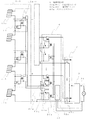
図4は、この発明の実施の形態1にかかる太陽光発電システムのシステム構成図である。図4において、太陽光発電システム100は、太陽電池アレイ1、接続箱2、パワーコンディショナ3に、太陽電池ストリングス内の各太陽電池モジュールを連結するための複数個の太陽電池モジュール間電路開閉器4および各太陽電池ストリングスに対して連結を許可するか否かの指令すなわち連結制御指令を出力する連結制御手段としての連結制御装置5を加えた構成となっている。
太陽電池アレイ1は太陽電池ストリングス1−1、…、1−mから構成されており、各太陽電池ストリングスは複数枚の太陽電池モジュール11a、11b、…、11n−1、11nが直列に接続された構成となっている。ここで、直列接続された2枚の太陽電池モジュール間の電路の途中に太陽電池モジュール間電路開閉器4がそれぞれ配置される。
Next, the solar power generation system according to
FIG. 4 is a system configuration diagram of the photovoltaic power generation system according to
The
太陽電池モジュール間電路開閉器4は、電路を開閉する開閉手段としての電路開閉リレー41、次段の太陽電池モジュール間電路開閉器への開閉制御出力を出力する出力手段としての制御出力リレー42から構成されている。
太陽電池モジュール11a、11bの間に配置される初段の太陽電池モジュール間電路開閉器4aにおいて、電路開閉リレー41aの接点は、一端が太陽電池モジュール11aの正電極(+)側からの出力ケーブルに接続、他端が太陽電池モジュール11bの負電極(−)側からの出力ケーブルに接続される。また、制御出力リレー42aの接点は、一端が電路開閉リレー41aの接点の他端側に接続され、他端が開閉制御出力端Oとして、次段の太陽電池モジュール間電路開閉器4bの開閉制御入力端Iに信号線を介して接続される。電路開閉リレー41aのコイルおよび制御出力リレー42aのコイルは並列に接続され、その一端側が電路開閉リレー41aの接点の一端に接続されて、その他端側が開閉制御入力端Iとして、連結制御装置5の開閉制御出力端Oに信号線を介して接続される。
二段目以降の太陽電池モジュール間電路開閉器4b、…、4n−1も同様に接続される。ただし、それぞれの開閉制御入力端Iは前段の太陽電池モジュール間電路開閉器の開閉制御出力端Oに接続され、最終段の太陽電池モジュール間電路開閉器4n−1の開閉制御出力端Oは次段の太陽電池モジュール間電路開閉器がないので何にも接続されない。
The
In the first-stage solar cell module circuit switch 4a disposed between the solar cell modules 11a and 11b, one end of the contact of the circuit switch relay 41a is connected to the output cable from the positive electrode (+) side of the solar cell module 11a. The other end of the connection is connected to the output cable from the negative electrode (−) side of the solar cell module 11b. Further, one end of the contact of the control output relay 42a is connected to the other end side of the contact of the electric circuit switching relay 41a, and the other end is used as the switching control output terminal O, so that the switching control of the electric circuit switch 4b between the solar cell modules in the next stage is performed. The input terminal I is connected via a signal line. The coil of the electric circuit switching relay 41a and the coil of the control output relay 42a are connected in parallel, one end side thereof is connected to one end of the contact of the electric circuit switching relay 41a, and the other end side is used as the switching control input terminal I. The switching control output terminal O is connected via a signal line.
The solar cell module circuit switches 4b,..., 4n-1 after the second stage are also connected in the same manner. However, each switching control input terminal I is connected to the switching control output terminal O of the preceding solar cell module circuit switch, and the switching control output terminal O of the final photovoltaic module switch 4n-1 is the next switching control output terminal O. Since there is no electric circuit switch between the solar cell modules of the stage, it is not connected to anything.
連結制御装置5は、系統電圧監視手段50、各太陽電池ストリングスに対応した連結指令手段としての複数の連系許可リレー52a、…、52mおよび自立運転許可手段としての複数の自立切替スイッチ51a、…、51mから構成されている。系統電圧監視手段50の入力は商用電力系統31の相間に接続され、系統電圧監視手段50の出力は連系許可リレー52a、…、52mの各コイルに接続される。また、連系許可リレー52a、…、52mの接点は、一端がそれぞれ対応する太陽電池ストリングスの最低電位側の出力端Nに、他端がそれぞれ自立切替スイッチ51a、…、51mのNC端子(連系運転側)に接続される。また、自立切替スイッチ51a、…、51mは、COM端子が開閉制御出力端Oとして、それぞれ対応する太陽電池ストリングス内の初段の太陽電池モジュール間電路開閉器4aの開閉制御入力端Iすなわち並列接続された電路開閉リレー41aコイルおよび制御出力リレー42aのコイルの他端側に、NO端子(自立運転側)がそれぞれ対応する太陽電池ストリングスの出力端Nに、NC端子(連系運転側)がそれぞれ連系許可リレー52a、…、52mの接点の他端に接続される。
また、太陽電池ストリングス1−1、…、1−mの最大電位側の出力端P、最低電位側の出力端Nはそれぞれ接続箱2内の直流開閉器21a、…、21mの入力側に接続される。
The
Further, the output terminal P on the maximum potential side and the output terminal N on the lowest potential side of the solar cell strings 1-1, ..., 1-m are connected to the input side of the DC switches 21a, ..., 21m in the
なお、本構成においては、太陽電池モジュール間の電路の途中に太陽電池モジュール間電路開閉器を配置し、制御信号を伝えるための制御線を初段から最終段までディジーチェーン的に配線することで実現しており、また、火災検知手段と連動する特別な専用装置を必要としない。したがって、既設の太陽光発電システムに対し、あとから必要な機器を追加し、簡単な配線工事を行うことで本構成への改造が簡単に実施できる。 In addition, in this configuration, it is realized by arranging the inter-solar cell module circuit switch in the middle of the electric circuit between the solar cell modules and wiring the control lines for transmitting control signals in a daisy chain from the first stage to the last stage. In addition, there is no need for a special dedicated device that works with the fire detection means. Therefore, it is possible to easily modify the present configuration by adding necessary devices to the existing photovoltaic power generation system and performing simple wiring work.
次に実施の形態1の動作について説明する。
まず、通常の連系運転時の動作を説明する。自立切替スイッチ51aはCOM端子とNC端子とが接続している状態すなわち連系運転側に切り替えられているものとする。また、連結制御装置5内の系統電圧監視手段50が商用電力系統31の相間電圧を監視していて、電圧が正常すなわち太陽光発電システムが連系可能な状態であれば連系許可リレー52aの接点をON状態に駆動するものとする。この状態は、太陽電池モジュール間電路開閉器4aから見ると開閉制御入力がON(閉路指示)状態であるということである。ここで、朝、太陽が昇って日射量が増加してくると、太陽電池ストリングス1−1の各太陽電池モジュール11a、11b、…、11nが発電動作を開始し、それぞれ発電量が増加してくる。すると、初段(最低電位側)の太陽電池モジュール11aの発電した電流が、太陽電池モジュール11aの正電極(+)から太陽電池モジュール間電路開閉器4aの電路開閉リレー41aのコイルおよび制御出力リレー42aのコイルを介し、連結制御装置5内の自立切替スイッチ51aのCOM端子からNC端子(連系運転側)、連系許可リレー52aの接点、太陽電池モジュール11aの負電極(−)へと続く経路で流れる。この電流が電路開閉リレー41a、制御出力リレー42aの動作電流以上であれば、電路開閉リレー41aの接点、制御出力リレー42aの接点がともに閉じる。すなわち、太陽電池モジュール11aと太陽電池モジュール11bとの間の電路が閉じる。
Next, the operation of the first embodiment will be described.
First, the operation during normal interconnection operation will be described. It is assumed that the self-supporting changeover switch 51a is switched to the state where the COM terminal and the NC terminal are connected, that is, to the connected operation side. Moreover, if the system voltage monitoring means 50 in the
また、制御出力リレー42aの接点が閉じることは、次段の太陽電池モジュール間電路開閉器4bへの開閉制御出力がON(閉路指示)になることを意味し、これによって太陽電池モジュール11b、太陽電池モジュール間電路開閉器4b内の電路開閉リレー41bのコイルおよび制御出力リレー42bのコイル、制御出力リレー42aの接点による閉回路が形成されて、そこに太陽電池モジュール11bの発電電流が流れる。それによって、太陽電池モジュール間電路開閉器4b内の電路開閉リレー41bの接点および制御出力リレー42bの接点が閉じる。すなわち、太陽電池モジュール11bと次段の太陽電池モジュールとの電路が閉じる。このようにして、太陽電池ストリングス内に直列配置された各太陽電池モジュール間の電路が最低電位側から順番に閉じていき、最後に最大電位側の太陽電池モジュール間の電路が閉じて、最終的に太陽電池ストリングス1−1の全太陽電池モジュール間の電路が閉じた状態すなわち太陽電池ストリングス1-1が連結状態となって、太陽電池ストリングス1-1による直流電力が接続箱2内の直流開閉器21aに入力される。
In addition, closing the contact of the control output relay 42a means that the switching control output to the next-stage solar cell module electric circuit switch 4b is turned ON (closed instruction), thereby the solar cell module 11b, the solar A closed circuit is formed by the coil of the electric circuit switching relay 41b, the coil of the control output relay 42b, and the contact of the control output relay 42a in the electric circuit switch 4b between the battery modules, and the generated current of the solar cell module 11b flows there. Thereby, the contact of the electric circuit switching relay 41b and the contact of the control output relay 42b in the electric circuit switch 4b between the solar cell modules are closed. That is, the electric circuit between the solar cell module 11b and the next-stage solar cell module is closed. In this way, the electric circuit between the solar cell modules arranged in series in the solar cell string is closed in order from the lowest potential side, and finally the electric circuit between the solar cell modules on the maximum potential side is closed and finally In the state where the electric circuit between all the solar cell modules of the solar cell string 1-1 is closed, that is, the solar cell string 1-1 is connected, and the DC power by the solar cell string 1-1 is DC open / closed in the
他の太陽電池ストリングスにおいても同様の動作となり、接続箱2は全太陽電池ストリングスからの直流電力を入力し、それらを1つに集電して太陽電池アレイ1の発電電力としてパワーコンディショナ3に送る。パワーコンディショナ3は接続箱2からの直流電力を交流電力に変換する。その交流電力は住宅内の電気機器等の負荷で消費され、余剰があれば商用電力系統31に逆潮流される。以上が連系運転時の動作である。
The operation is the same in other solar cell strings, and the
ここで、太陽電池モジュール間電路開閉器4内の電路開閉リレー41、制御出力リレー42が必要とする仕様、性能について詳しく説明する。本実施の形態で使用可能な太陽電池モジュールとして、例えば公称最大出力200W、公称最大出力動作電圧25V、公称最大出力電流8A、公称開放電圧DC32Vの太陽電池モジュールが上げられる。図3(a)(b)に示したように、一般に太陽電池モジュールは太陽からの日射量の増減によりその出力電力値、出力電流値が増減するが、出力電圧は低日射時においても出力電流が少なければ高い電圧値となり、開放電圧(出力電流=0のときの出力電圧)としてDC25V以上が可能である。したがって、電路開閉リレー41として定格コイル電圧DC24Vのリレーを使用すれば、その動作電圧は一般的にDC21V以下となるため、低日射時の太陽電池モジュール1枚の発電電圧で駆動することが可能である。また、接点定格がDC400V/DC25Aレベルのリレーであればコイル消費電力も2W以下が期待でき、太陽電池モジュールの発電電力が数Wしかない低日射時においてもリレーの駆動が可能となる。なお、制御出力リレー42は電路開閉リレー41に比べて接点開閉能力が小容量で良いことから、コイル消費電力が0.2Wクラスのさらに小型のリレーを使用することができる。
Here, the specifications and performance required by the electric
また、パワーコンディショナが起動し、太陽電池モジュールから発電電流として大きな値の電流を取り出すことで太陽電池モジュールの発電電圧が低下したとしても、リレーの特性として、接点が閉じた状態から開放状態に切り替わる復帰電圧は定格電圧の10%程度、例えば定格電圧DC24Vのリレーなら復帰電圧DC5V以上であるため、リレーが一度ON動作したならば、太陽電池ストリングスの発電電圧がパワーコンディショナが動作を停止するような低電圧例えば50V以下程度まで低下した場合でも、電路開閉リレーによる太陽電池モジュール間電路の閉路および制御出力リレーによる次段への閉路指示(開閉制御出力ON)を継続することが可能であり、安定した太陽電池ストリングスの接続すなわち連結が可能である。 Moreover, even if the power conditioner is activated and the generated voltage of the solar cell module is reduced by taking out a large current as the generated current from the solar cell module, the relay characteristics change from the closed state to the open state. The return voltage to be switched is about 10% of the rated voltage. For example, if the relay has a rated voltage of DC 24V, the return voltage is DC 5V or more. Therefore, once the relay is turned ON, the power generation voltage of the solar cell string stops the operation of the power conditioner. Even when such a low voltage drops to about 50 V or less, it is possible to continue the closing of the electric circuit between the solar cell modules by the electric circuit opening / closing relay and the closing instruction (opening / closing control output ON) to the next stage by the control output relay. A stable connection of solar cell strings is possible.
次に、連系運転中に火災が発生した場合の動作について説明する。消火活動時に商用電力系統を遮断すなわち停電状態とすることにより、連結制御装置5内の系統電圧監視手段50が商用電力系統31の相間電圧異常(停電)を検知し、連系許可リレー52aの接点をOFF状態にする。そのため、太陽電池モジュール11aの正電極(+)から太陽電池モジュール間電路開閉器4aの電路開閉リレー41aのコイルおよび制御出力リレー42aのコイルを経由し、連結制御装置5内の自立切替スイッチ51aのCOM端子からNC端子(連系運転側)、連系許可リレー52aの接点、太陽電池モジュール11aの負電極(−)へとつながる電流経路が遮断されるため、電路開閉リレー41aの接点、制御出力リレー42aの接点がともに開く。すなわち、太陽電池モジュール11aと太陽電池モジュール11bとの間の電路が開く。
Next, the operation when a fire occurs during the interconnected operation will be described. By shutting off the commercial power system at the time of fire extinguishing activity, that is, in a power failure state, the system voltage monitoring means 50 in the
また、制御出力リレー42aの接点が開くことは、次段の太陽電池モジュール間電路開閉器4bへの開閉制御出力がOFF(開路指示)になることを意味し、これによって太陽電池モジュール11b、太陽電池モジュール間電路開閉器4b内の電路開閉リレー41bのコイルおよび制御出力リレー42bのコイル、制御出力リレー42aの接点による電流経路が遮断されるため、そこに太陽電池モジュール11bの発電電流が流れなくなる。それによって、太陽電池モジュール間電路開閉器4b内の電路開閉リレー41bの接点および制御出力リレー42bの接点が開く。すなわち、太陽電池モジュール11bと次段の太陽電池モジュールとの電路が開く。このようにして、太陽電池ストリングス内で直列接続されていた各太陽電池モジュール間の電路が最低電位側から順番に開いていき、最後に最大電位側の太陽電池モジュール間の電路が開いて、短時間で太陽電池ストリングス内の各太陽電池モジュールの電路が全て開いた状態となる。 Further, the opening of the contact of the control output relay 42a means that the opening / closing control output to the next-stage solar cell module electric circuit switch 4b is turned OFF (opening instruction), thereby the solar cell module 11b, the solar Since the current path by the contact of the coil of the electric circuit switching relay 41b, the coil of the control output relay 42b and the control output relay 42a in the electric circuit switch 4b between the battery modules is interrupted, the generated current of the solar cell module 11b does not flow there. . Thereby, the contact of the electric circuit switching relay 41b and the contact of the control output relay 42b in the electric circuit switch 4b between the solar cell modules are opened. That is, the electric circuit between the solar cell module 11b and the next-stage solar cell module is opened. In this way, the electric circuit between the solar cell modules connected in series in the solar cell string sequentially opens from the lowest potential side, and finally the electric circuit between the solar cell modules on the maximum potential side opens, With time, all the electric circuits of the respective solar cell modules in the solar cell string are opened.
他の太陽電池ストリングスにおいても同様の動作となり、太陽電池アレイ1を形成する各太陽電池モジュール間の電路が全て開いた状態になる。したがって、たとえ日中すなわち日射のある状態であっても、各太陽電池モジュール毎に開放電圧としてDC32V程度の電圧が発生するだけになり、感電の恐れのある高電圧ではなくなるため、消防隊員は安全に消火活動、放水活動を行うことができる。
The same operation is performed in the other solar cell strings, and all the electric circuits between the solar cell modules forming the
なお、上記説明では、火災発生時に商用電力系統を遮断することにより、連結制御装置5内の系統電圧監視手段50が各太陽電池モジュール間の電路を遮断する指示を出す例を示したが、系統電圧監視手段50の代わりに災害監視手段としてもよい。すなわち、災害監視手段としては、建物に設置されている火災警報器等からの警報出力を取り込み、それに基づいて各太陽電池モジュール間の電路を遮断する指示を出す機能さえ有していれば、上記の説明と同様、簡単な構成の装置および簡単な配線工事によって、太陽電池ストリングスの発生する高電圧を安全な低電圧に分断して、消火活動における感電の危険性を小さくすることができる。また、系統電圧監視手段と災害監視手段の両方を備え、系統停電あるいは火災警報等の少なくとも一つが発生した際に各太陽電池モジュール間の電路を遮断する指示を出すようにしてもよい。
In the above description, an example is shown in which the system voltage monitoring means 50 in the
次に、非常時の電源として太陽光発電システムを自立運転させる場合の動作について説明する。
一般的なパワーコンディショナは非常用電源としての自立運転の機能を有しており、地震等の災害が発生して商用電力系統が長期にわたって停電するような事態になったとき、商用電力系統との連系を行わない状態でも、太陽電池ストリングスからの発電電圧の入力により、住宅内の負荷に供給する交流電力の出力を行うことが可能である。
本実施の形態における太陽光発電システム100において、通常の運転(連系運転)では系統の停電を検知した場合に各太陽電池モジュール間の連結を解除するため、パワーコンディショナ3への入力がない状態となる。このような状態の時に自立運転させたい場合は、連結制御装置5内の自立切替スイッチ51aをCOM端子とNO端子とが接続する状態すなわち自立運転側に切り替える。言い換えるならば、自立運転を許可するための第二の連結制御指令を出力する操作を行う。日射量が十分あって、太陽電池ストリングス1−1の各太陽電池モジュール11a、11b、…、11nが発電を行っているものとすると、初段(最低電位側)の太陽電池モジュール11aの発電した電流が、太陽電池モジュール11aの正電極(+)から太陽電池モジュール間電路開閉器4aの電路開閉リレー41aのコイルおよび制御出力リレー42aのコイルを経由し、連結制御装置5内の自立切替スイッチ51aのCOM端子からNO端子(自立運転側)、太陽電池モジュール11aの負電極(−)へと続く経路で流れる。これにより、電路開閉リレー41aの接点および制御出力リレー42aの接点がともに閉じる。すなわち、太陽電池モジュール11aと太陽電池モジュール11bとの間の電路が閉じるとともに次段の太陽電池モジュール間電路開閉器4bへの開閉制御出力がON(閉路指示)になる。
Next, the operation when the photovoltaic power generation system is operated independently as an emergency power source will be described.
A general power conditioner has a function of self-sustained operation as an emergency power source. When a disaster such as an earthquake occurs and the commercial power system goes out of power for a long time, Even in the state where the interconnection is not performed, it is possible to output the AC power supplied to the load in the house by the input of the generated voltage from the solar cell strings.
In the photovoltaic
以下同様にして各太陽電池モジュール間の電路が閉じられ、太陽電池ストリングス1−1において全太陽電池モジュールが連結状態となる。また、他の太陽電池ストリングスにおいても同様の動作となり、各太陽電池ストリングスのそれぞれの発電電力が接続箱2に入力されて1つに集電された後、パワーコンディショナ3に送られる。この発電電力を受けて、パワーコンディショナ3は自立運転を実施することが可能となる。
なお、本実施の形態において、各太陽電池モジュール間電路開閉器4内の電路開閉リレー41のコイルおよび制御出力リレー42のコイルを駆動する電源は、商用電力系統からではなく各太陽電池モジュールから供給される構成となっているため、日射があれば系統停電時においても各太陽電池モジュールの連結が可能であり、自立運転を実施するのに適している。
Similarly, the electric circuit between the solar cell modules is closed, and all the solar cell modules are connected in the solar cell string 1-1. The same operation is performed in other solar cell strings, and the generated power of each solar cell string is input to the
In the present embodiment, the power source for driving the coil of the electric
実施の形態1では上記のように構成されているため、簡単な構成の装置の追加および簡単な配線工事によって、通常は日射量の増加に伴い自動的に太陽電池モジュール間の電路が連結されて連系運転を行い、火災が発生した場合は太陽電池モジュール間の電路を即座に遮断して消防隊員の安全な消火活動を可能とするという効果を奏する。
さらに、抵抗器の接続で電流を増大させて電圧低下させるのではなく、太陽電池モジュール間の直列連結を十分な低電圧レベルに分断する方式としているので、より信頼性の高い感電回避が可能となっている。
また、太陽電池モジュールの特性に適合した電路開閉器の仕様を設定することにより、低日射時に太陽電池モジュールの発電電力が低下しても、電路の連結状態を維持して、安定した太陽電池ストリングスの発電出力の供給を継続することが可能である。
また、太陽電池モジュール間電路開閉器は、太陽電池モジュールの発電電力を利用して動作するため、特別な電源装置を必要とせず、安価で簡単な構成により実現することができる。
また、連結制御装置は自立運転許可手段を備えているので、災害時等の長期停電状態において、系統電圧が生じていない状態であっても太陽電池ストリングスの各太陽電池モジュールを連結させて自立運転を実施させることが可能である。
Since the first embodiment is configured as described above, an electric circuit between solar cell modules is usually automatically connected with an increase in the amount of solar radiation by adding a device with a simple configuration and a simple wiring work. In the event of a fire, there is an effect that the fireworks can be safely extinguished by immediately shutting off the electric circuit between the solar cell modules when a fire breaks out.
Furthermore, instead of increasing the current by connecting resistors to lower the voltage, the series connection between the solar cell modules is divided to a sufficiently low voltage level, so it is possible to avoid electric shock with higher reliability. It has become.
In addition, by setting the specifications of the electric circuit switch suitable for the characteristics of the solar cell module, even if the generated power of the solar cell module decreases during low solar radiation, the connection state of the electric circuit is maintained and stable solar cell strings It is possible to continue supplying the power generation output.
Moreover, since the electric circuit switch between solar cell modules operates using the generated electric power of the solar cell module, it does not require a special power supply device and can be realized with an inexpensive and simple configuration.
In addition, since the connection control device is provided with a self-sustained operation permission means, in a long-time power outage state such as a disaster, even if a system voltage is not generated, the solar cell modules of the solar cell strings are connected and operated independently. Can be implemented.
実施の形態2.
実施の形態1における太陽光発電システムでは、各太陽電池モジュール間の電路を連結して形成された太陽電池ストリングスの出力を直接接続箱に入力する構成とした。実施の形態2における太陽光発電システムでは、さらに太陽電池ストリングスと接続箱との間の電路を開閉する手段を備える構成としたものである。
図5は実施の形態2にかかる太陽光発電システムのシステム構成図である。以下、図5により実施の形態2の構成と動作を説明する。
連結制御装置6は、前述した系統電圧監視手段50、複数の連系許可リレー52a、…、複数の自立切替スイッチ51a、…に加えて、各太陽電池ストリングスと接続箱内の直流開閉器との間の電路を開閉するストリングス開閉手段としての複数のストリングスリレー63a、…、各ストリングスリレーの開閉を制御する複数のストリングス連結許可リレー62a、…および自立切替スイッチ51a、…と連動する第二の自立切替スイッチ61a、…により構成される。
In the solar power generation system in
FIG. 5 is a system configuration diagram of the photovoltaic power generation system according to the second embodiment. The configuration and operation of the second embodiment will be described below with reference to FIG.
In addition to the system voltage monitoring means 50, the plurality of interconnection permission relays 52a,..., The plurality of independent switching switches 51a,..., The
次に、上記の接続について太陽電池ストリングス1−1に関連する部分を代表として説明する。ストリングスリレー63aの接点は、一端が太陽電池ストリングス1−1の最大電位側の出力端Pに接続され、他端が接続箱2内の直流開閉器21aの入力側に接続される。すなわち、太陽電池ストリングス1−1と接続箱2との間の電路の途中に挿入されている。ストリングスリレー63aのコイルは、一端がストリングスリレー63aの接点の一端に、他端がストリングス連結許可リレー62aの接点の一端および第二の切替スイッチ61aのCOM端子に接続される。ストリングス連結許可リレー62aの接点の他端は、第二の自立切替スイッチ61aのNO端子とともに太陽電池ストリングス1−1内の最終段の太陽電池モジュール間電路開閉器4n−1の制御出力リレー42n−1の接点の他端すなわち次段への開閉制御出力端Oに接続される。ストリングス連結許可リレー62aのコイルは、連系許可リレー52aのコイルと同様に系統電圧監視手段50の出力に接続される。その他の構成は実施の形態1(図4)と同じなので説明を省略する。
Next, the above connection will be described with a portion related to the solar cell string 1-1 as a representative. One end of the contact point of the string relay 63a is connected to the output terminal P on the maximum potential side of the solar cell string 1-1, and the other end is connected to the input side of the DC switch 21a in the
次に実施の形態2の動作について説明する。
まず、通常の連系運転時の動作を説明する。自立切替スイッチ51aがCOM端子とNC端子とが接続している状態すなわち連系運転側に切り替えられていると、連動している第二の切替スイッチ61aもCOM端子とNC端子とが接続している状態すなわちCOM端子とNO端子とが開放されている状態となる。また、連結制御装置6内の系統電圧監視手段50が商用電力系統31の相間電圧を監視し、正常であれば連系許可リレー52aの接点およびストリングス連結許可リレー62aの接点をON状態に駆動する。ここで、朝、太陽が昇って日射量が増加してくると、太陽電池ストリングス1−1の各太陽電池モジュール11a、11b、…、11nが発電動作を開始し、それぞれ発電量が増加してくる。それによって、前述したように各太陽電池モジュール間電路開閉器の電路開閉リレーおよび制御出力リレーが閉じられ、太陽電池ストリングス1−1は全連結状態となる。そして最終段の太陽電池モジュール間電路開閉器4n−1の制御出力リレー42n−1も閉じた状態となる。これにより、最終段の太陽電池モジュール11n、連結制御装置6内のストリングスリレー63aのコイル、ストリングス連結許可リレー62aの接点、太陽電池モジュール間電路開閉器4n−1の制御出力リレー42n−1の接点による閉回路が形成されて、そこに太陽電池モジュール11nの発電電流が流れる。したがって、連結制御装置6内のストリングスリレー63aの接点が閉じる。すなわち、太陽電池ストリングス1−1と接続箱2との間の電路が閉じる。他の太陽電池ストリングスにおいても同様の動作となり、各太陽電池ストリングスの発電電力がそれぞれのストリングスリレー63を介して接続箱2に入力され、接続箱2で集電された後、パワーコンディショナ3に供給されて連系運転が行われる。
Next, the operation of the second embodiment will be described.
First, the operation during normal interconnection operation will be described. When the self-supporting changeover switch 51a is switched to the state where the COM terminal and the NC terminal are connected, that is, to the connected operation side, the second changeover switch 61a that is interlocked is also connected to the COM terminal and the NC terminal. In other words, the COM terminal and the NO terminal are open. Moreover, the system voltage monitoring means 50 in the
連系運転中に火災が発生した場合は、実施の形態1同様、系統電圧監視手段50により連結制御装置6の連系許可リレー52aの接点が開放されるため、太陽電池ストリングス1−1の各太陽電池モジュール間電路開閉器が次々と太陽電池モジュール間の電路を遮断し、全ての連結が解除される。したがって、日射のある状態だったとしても、各太陽電池モジュール毎に開放電圧であるDC32V程度の電圧が発生するだけの状態となり、消火活動、放水活動において消防隊員が感電する危険性を小さくすることができる。
When a fire occurs during the interconnection operation, the contact of the interconnection permission relay 52a of the
なお、非常時の電源として自立運転させる場合の動作について説明すると、自立切替スイッチ51aをCOM端子とNO端子とが接続している状態すなわち自立運転側に切り替えることにより、連動している第二の切替スイッチ61aもCOM端子とNO端子とが接続している状態に切り替わる。日射があって各太陽電池モジュールが発電できる状態であれば、自立切替スイッチ51aを介して初段の太陽電池モジュール用電路開閉器4aの電路が閉じ、それに伴って次段以降の太陽電池モジュール用電路開閉器も順次電路を閉じていき、最後に太陽電池モジュール11n、ストリングスリレー63aのコイル、第二の切替スイッチ61a、制御出力リレー42n−1の接点で形成される経路に太陽電池モジュール11nの発電電流が流れて、ストリングスリレー63aの接点が閉じる。すなわち、太陽電池ストリングス1−1が連結状態になるとともに接続箱2との電路が閉じられ、パワーコンディショナ3に直流電力が供給される。したがって、実施の形態2においても自立運転が実施可能な構成となっている。
Note that the operation in the case of performing an independent operation as an emergency power source will be described. By switching the independent switch 51a to the state where the COM terminal and the NO terminal are connected, that is, to the independent operation side, the second interlocked operation is performed. The changeover switch 61a is also switched to a state where the COM terminal and the NO terminal are connected. If there is solar radiation and each solar cell module can generate electric power, the electric circuit of the first-stage solar cell module circuit switch 4a is closed via the self-supporting changeover switch 51a. The switch also sequentially closes the electric circuit, and finally, the power generation of the solar cell module 11n in the path formed by the contact of the solar cell module 11n, the coil of the strings relay 63a, the second changeover switch 61a, and the control output relay 42n-1. A current flows, and the contacts of the strings relay 63a are closed. That is, the solar cell string 1-1 is connected and the electric circuit with the
実施の形態2においては、上記のように太陽電池ストリングス内の太陽電池モジュールの連結が完了した後にストリングスリレー63の接点をONする構成としているため、各太陽電池モジュール間電路開閉器内の電路開閉リレーが閉じていく段階では太陽電池ストリングスおよび接続箱2、パワーコンディショナ3による閉回路が形成されていないので、各電路開閉リレーの接点が大電流の流れる電路を閉じることはなく、最後のストリングスリレー63の接点が閉じる時になって閉回路が形成され電流が流れることになる。すなわち、各電路開閉リレーとしては最大開閉電流が小さいものを使用することが可能であり、また、開閉電流に起因する接点溶着や摩耗等の故障・劣化の発生を低減することができる。
また、日没時や低日射時における太陽電池ストリングスの電圧低下の際は、パワーコンディショナ3の動作可能範囲の設定によりパワーコンディショナ3を先に停止させることで、太陽電池ストリングス、接続箱2およびパワーコンディショナ3による閉回路を開いて電流の流れがなくなった後で各太陽電池モジュール間電路開閉器内の電路開閉リレーが開くように構成することが可能であるため、電路開閉リレーとしては開路動作時においても大電流を開くことがないので、最大開閉電流が小さいものを使用することが可能であるとともにその接点溶着や摩耗等の故障・劣化の発生を低減することができる。
In the second embodiment, since the contact of the strings relay 63 is turned on after the connection of the solar cell modules in the solar cell strings is completed as described above, the electric circuit switching in the electric circuit switches between the solar cell modules is performed. At the stage where the relay is closed, a closed circuit is not formed by the solar cell strings, the
In addition, when the voltage of the solar cell strings decreases during sunset or low sunlight, the solar cell strings and the
実施の形態2では上記のように構成されているため、実施の形態1と同様、簡単な構成の装置の追加および簡単な配線工事によって、通常は日射量の増加に伴い自動的に太陽電池モジュール間の電路が連結されて連系運転を行い、火災が発生した場合は太陽電池モジュール間の電路を簡単に遮断して消防隊員の安全な消火活動を可能とする等の効果を奏する。
また、起動時は各太陽電池モジュール間電路開閉器内の電路開閉リレーが全て閉じてからストリングスリレーが閉じ、日没時の電圧低下時は電路開閉リレーの開放より先にパワーコンディショナを停止させる構成が可能であるため、電路開閉リレーの接点が大電流を開閉することがなくなり、接点の最大開閉電流を下げることや故障・劣化の発生を低減することが可能となって、長期にわたる開閉動作に対して安価で高寿命な構成を実現するという効果が得られる。
Since the second embodiment is configured as described above, as in the first embodiment, a solar cell module is usually automatically added as the amount of solar radiation increases by adding a device having a simple configuration and performing a simple wiring work. In the event of a fire, the circuit between the solar cell modules can be easily interrupted to enable fire fighters to perform safe fire extinguishing activities.
Also, when starting up, the string relays close after all the circuit switching relays in the circuit switches between the solar cell modules are closed, and when the voltage drops at sunset, the power conditioner is stopped before the circuit switching relays are opened. Because it is possible to configure, the contact of the circuit switching relay does not open and close a large current, the maximum switching current of the contact can be reduced and the occurrence of failure / deterioration can be reduced. On the other hand, an effect of realizing an inexpensive and long-life configuration can be obtained.
実施の形態3.
実施の形態2における太陽光発電システムでは、太陽電池ストリングスと接続箱との電路を開閉するストリングスリレーが太陽電池ストリングスの最終段に位置する太陽電池モジュール間電路開閉器からの開閉制御出力および連系許可リレーによって開閉される構成とした。実施の形態3における太陽光発電システムでは、太陽電池ストリングスの電圧を検知し、その電圧レベルによってストリングスリレーの開閉を制御する構成としたものである。
図6は実施の形態3にかかる太陽光発電システムのシステム構成図である。以下、図6により実施の形態3の構成と動作を説明する。
連結制御装置7は、前述した系統電圧監視手段50、複数の連系許可リレー52a、…、複数の自立切替スイッチ51a、…、複数のストリングスリレー63a、…に加えて、各太陽電池ストリングスの電圧を監視し、その電圧値に基づいて各ストリングスリレーの開閉を制御するストリングス電圧検知手段としての複数の電圧監視装置71a、…により構成される。
In the photovoltaic power generation system according to the second embodiment, the string relay that opens and closes the electric path between the solar cell strings and the connection box is the open / close control output and the interconnection from the inter-solar cell electric circuit switch located at the final stage of the solar cell strings. It is configured to be opened and closed by a permission relay. In the photovoltaic power generation system according to
FIG. 6 is a system configuration diagram of the photovoltaic power generation system according to the third embodiment. The configuration and operation of the third embodiment will be described below with reference to FIG.
In addition to the system voltage monitoring means 50, the plurality of interconnection permission relays 52a,..., The plurality of independent switches 51a,..., The plurality of strings relays 63a,. And a plurality of voltage monitoring devices 71a,... As string voltage detecting means for controlling the opening and closing of each string relay based on the voltage value.
次に、上記の接続について太陽電池ストリングス1−1に関連する部分を代表として説明する。ストリングスリレー63aの接点は、実施の形態2同様、一端が太陽電池ストリングス1−1の最大電位側の出力端Pに接続され、他端が接続箱2内の直流開閉器21aの入力側に接続される。電圧監視装置71aは、入力端iが太陽電池ストリングス1−1の出力端Pに、GND端が自立切替スイッチ51aのCOM端子側に、出力端oがストリングスリレー63aのコイルの一端に接続される。ストリングスリレー63aのコイルの他端は、電圧監視装置71aのGND端側に接続される。その他の構成は実施の形態1(図4)と同じなので説明を省略する。
Next, the above connection will be described with a portion related to the solar cell string 1-1 as a representative. As with the second embodiment, one end of the string relay 63a is connected to the output terminal P on the maximum potential side of the solar cell string 1-1 and the other end is connected to the input side of the DC switch 21a in the
次に実施の形態3の動作について説明する。
まず、通常の連系運転時の動作を説明する。自立切替スイッチ51aはCOM端子とNC端子とが接続している状態すなわち連系運転側に切り替えられているものとする。また、連結制御装置7内の系統電圧監視手段50が商用電力系統31の相間電圧を監視していて、電圧が正常すなわち太陽光発電システムが連系可能な状態であれば連系許可リレー52aの接点をON状態に駆動するものとする。ここで、朝、太陽が昇って日射量が増加してくると、太陽電池ストリングス1−1の各太陽電池モジュール11a、11b、…、11nが発電動作を開始し、前述したように各太陽電池モジュール間電路開閉器の電路開閉リレーおよび制御出力リレーが順次閉じられ、太陽電池ストリングス1−1が全連結状態となる。
Next, the operation of the third embodiment will be described.
First, the operation during normal interconnection operation will be described. It is assumed that the self-supporting changeover switch 51a is switched to the state where the COM terminal and the NC terminal are connected, that is, to the connected operation side. Moreover, if the system voltage monitoring means 50 in the
太陽電池ストリングス1−1の出力端P−N間に自立切替スイッチ51a、連系許可リレー52aを介して接続された電圧監視装置71aは、太陽電池ストリングス1−1のストリングス電圧(PN間電圧)を監視し、ストリングス電圧が第一の所定値以上になったら、出力端oから閉路指令としてのリレー駆動出力を出力する。これによって、ストリングスリレー63aのコイルに駆動電流が流れ、ストリングスリレー63aの接点が閉じる。すなわち、太陽電池ストリングス1−1と接続箱2との間の電路が閉じる。なお、電圧監視装置71aの出力端oからのリレー駆動出力は太陽電池ストリングス1−1の発電電力を利用したものであり、系統停電時でも動作可能である。他の太陽電池ストリングスにおいても同様の動作となり、各太陽電池ストリングスの発電電力がそれぞれのストリングスリレーを介して接続箱2に入力され、接続箱2で集電された後、パワーコンディショナ3に供給されて連系運転が行われる。
The voltage monitoring device 71a connected between the output terminal PN of the solar cell string 1-1 via the self-supporting changeover switch 51a and the interconnection permission relay 52a is a string voltage (inter-PN voltage) of the solar cell string 1-1. When the string voltage becomes equal to or higher than the first predetermined value, a relay drive output as a closing command is output from the output terminal o. As a result, a drive current flows through the coil of the strings relay 63a, and the contacts of the strings relay 63a are closed. That is, the electric circuit between the solar cell strings 1-1 and the
連系運転中に火災が発生した場合は、実施の形態1同様、系統電圧監視手段50により連結制御装置7の連系許可リレー52aの接点が開放されるため、太陽電池ストリングス1−1の各太陽電池モジュール間電路開閉器が次々と太陽電池モジュール間の電路を遮断し、全ての連結が解除される。また、電圧監視装置71aが太陽電池ストリングス1−1の出力端P−N間から切り離されるため、ストリングスリレー63aの接点も開放される。したがって、日射のある状態だったとしても、各太陽電池モジュール毎に開放電圧であるDC32V程度の電圧が発生するだけの状態となり、消火活動、放水活動において消防隊員が感電する危険性を小さくすることができる。
When a fire occurs during the interconnection operation, the contact of the interconnection permission relay 52a of the
実施の形態3においては、上記のように太陽電池ストリングス内の太陽電池モジュールの連結が完了し、太陽電池ストリングス1−1全体での電圧が第一の所定値以上となった後にストリングスリレー63aの接点をONさせる構成としているので、各太陽電池モジュール間電路開閉器内の電路開閉リレーが閉じていく段階では太陽電池ストリングスおよび接続箱、パワーコンディショナによる閉回路がまだ形成されていないため、各電路開閉リレーの接点が大電流の流れる電路を閉じることはなく、最後のストリングスリレーの接点が閉じる時になって閉回路が形成され電流が流れることになる。すなわち、各電路開閉リレーとしては最大開閉電流が小さいものを使用することが可能であり、また、開閉電流に起因する接点溶着や摩耗等の故障・劣化の発生を低減することができる。 In the third embodiment, the connection of the solar cell modules in the solar cell strings is completed as described above, and the voltage of the string relay 63a is increased after the voltage across the solar cell strings 1-1 becomes equal to or higher than the first predetermined value. Since the contact is turned on, the closed circuit by the solar cell strings, connection box, and power conditioner is not yet formed at the stage where the electric circuit switching relay in the electric circuit switch between the solar cell modules is closed. The contact of the electric circuit switching relay does not close the electric circuit through which a large current flows, but a closed circuit is formed when the last string relay contact is closed, and current flows. That is, it is possible to use a relay with a small maximum switching current as each circuit switching relay, and it is possible to reduce the occurrence of failure / deterioration such as contact welding and wear due to the switching current.
また、日没時や低日射時における太陽電池ストリングスの電圧低下の際は、電圧監視装置71aがストリングス電圧(PN間電圧)を監視し、ストリングス電圧が第二の所定値以下になったら、開路指令として、電圧監視装置71aの出力端oからのリレー駆動出力を停止する。これによって、ストリングスリレー63aのコイルへの駆動電流が遮断され、ストリングスリレー63aの接点が開く。すなわち、太陽電池ストリングス1−1と接続箱2との間の電路が開く。なお、第二の所定値を適切に設定することにより、まずストリングスリレーを開いて太陽電池ストリングス、接続箱、パワーコンディショナの経路を流れる電流を停止させた後に、各太陽電池モジュール間電路開閉器内の電路開閉リレーが開くように構成することが可能であるため、電路開閉リレーとしては開路動作時においても大電流を開くことがないので、最大開閉電流が小さいものを使用することが可能であるとともにその接点溶着や摩耗等の故障・劣化の発生を低減することができる。
In addition, when the voltage of the solar cell string drops during sunset or low solar radiation, the voltage monitoring device 71a monitors the string voltage (inter-PN voltage), and when the string voltage falls below the second predetermined value, the circuit is opened. As a command, the relay drive output from the output end o of the voltage monitoring device 71a is stopped. As a result, the drive current to the coil of the strings relay 63a is cut off, and the contacts of the strings relay 63a are opened. That is, the electric circuit between the solar cell strings 1-1 and the
実施の形態3では上記のように構成されているため、実施の形態1と同様、簡単な構成の装置の追加および簡単な配線工事によって、通常は日射量の増加に伴い自動的に太陽電池モジュール間の電路が連結されて連系運転を行い、火災が発生した場合は太陽電池モジュール間の電路を簡単に遮断して消防隊員の安全な消火活動を可能とする等の効果を奏する。
また、起動時は各太陽電池モジュール間電路開閉器内の電路開閉リレーが全て閉じてからストリングスリレーを閉じ、日没時の電圧低下時は第二の所定値を適切に設定することによってストリングスリレーを開いてから電路開閉リレーが開く構成とすることが可能であるため、電路開閉リレーの接点が大電流を開閉することがなくなり、接点の最大開閉電流を下げることや故障・劣化の発生を低減することが可能となって、長期にわたる開閉動作に対して安価で高寿命な構成を実現するという効果が得られる。
さらに、メンテナンスにおいては主に大電流を開閉するストリングスリレーの点検、交換を行うことになり、効率のいい作業が実施できる。
Since the third embodiment is configured as described above, as in the first embodiment, a solar cell module is usually automatically added as the amount of solar radiation increases by adding a device having a simple configuration and performing a simple wiring work. In the event of a fire, the circuit between the solar cell modules can be easily interrupted to enable fire fighters to perform safe fire extinguishing activities.
In addition, when starting up, the string relays are closed after all the circuit switching relays in the circuit switch between each solar cell module are closed, and when the voltage drops at sunset, the strings relay is set by appropriately setting the second predetermined value. Since the circuit switching relay can be configured to open after opening the circuit, the contact of the circuit switching relay will not open or close a large current, reducing the maximum switching current of the contact and reducing the occurrence of failure or deterioration. Thus, an effect of realizing an inexpensive and long-life configuration for a long-time opening / closing operation can be obtained.
Furthermore, the maintenance mainly involves checking and replacing the string relay that opens and closes a large current, so that efficient work can be performed.
実施の形態4.
実施の形態1〜3における太陽光発電システムでは、太陽電池モジュール間電路開閉器内の電路開閉リレーおよび制御出力リレーを駆動する電源として太陽電池モジュールの発電する直流電力をそのまま使用する構成とした。実施の形態4における太陽光発電システムでは、太陽電池モジュールの発電する直流電力の電圧を電圧調整手段によって別の電圧値に変換し、その電圧で電路開閉リレー等を駆動する構成としたものである。
図7は実施の形態4にかかる太陽光発電システムのシステム構成図である。以下、図7により実施の形態4の構成と動作を説明する。
In the solar power generation system in Embodiments 1-3, it was set as the structure which uses the direct-current power which a solar cell module generates as it is as a power source which drives the electric circuit switching relay and control output relay in the electric circuit switch between solar cell modules. In the photovoltaic power generation system according to
FIG. 7 is a system configuration diagram of a photovoltaic power generation system according to the fourth embodiment. The configuration and operation of the fourth embodiment will be described below with reference to FIG.
太陽電池モジュール間電路開閉器8aは、電路を開閉する開閉手段としての電路開閉リレー41a、次段の太陽電池モジュール間電路開閉器への開閉制御出力を出力する出力手段としてのフォトカプラ82a、電圧調整手段としての電圧調整回路83a、バイパス防止ダイオード84a等により構成される。
電路開閉リレー41aの接点は、一端が太陽電池モジュール11aの正電極(+)側からの出力ケーブルに接続、他端が太陽電池モジュール11bの負電極(−)側からの出力ケーブルに接続される。電圧調整回路83aは、入力端iが電路開閉リレー41aの接点の一端側に接続、GND端がバイパス防止ダイオード84aのアノードに接続される。バイパス防止ダイオード84aのカソードは開閉制御入力端Iとして、連結制御装置5の開閉制御出力端Oに信号線を介して接続される。また、電圧調整回路83aの出力端oは、電路開閉リレー41aのコイルの一端および電流制限抵抗器85aの一端に接続される。電流制限抵抗器85aの他端は、フォトカプラ82aのフォトダイオードのアノードに接続される。フォトカプラ82aのフォトダイオードのカソードは、電路開閉リレー41aのコイルの他端とともに電圧調整回路83aのGND端すなわちバイパス防止ダイオード84aのアノードに接続される。フォトカプラ82aのフォトトランジスタのエミッタは電路開閉リレー41aの接点の他端側に接続され、フォトカプラ82aのフォトトランジスタのコレクタは開閉制御出力端Oとして、次段の太陽電池モジュール間電路開閉器8bの開閉制御入力端Iに信号線を介して接続される。
他の太陽電池モジュール間電路開閉器8b、…、8n−1も同様に接続される。その他の構成は実施の形態1(図4)と同じなので説明を省略する。
An inter-solar cell module circuit switch 8a includes an electric circuit switching relay 41a as an opening / closing unit that opens and closes an electric circuit, a photocoupler 82a as an output unit that outputs an opening / closing control output to an inter-solar cell module circuit switch, and a voltage. A voltage adjustment circuit 83a as an adjustment means, a bypass prevention diode 84a, and the like are included.
One end of the contact of the electric circuit switching relay 41a is connected to the output cable from the positive electrode (+) side of the solar cell module 11a, and the other end is connected to the output cable from the negative electrode (−) side of the solar cell module 11b. . The voltage adjustment circuit 83a has an input terminal i connected to one end of the contact of the electric circuit switching relay 41a, and a GND terminal connected to the anode of the bypass prevention diode 84a. The cathode of the bypass prevention diode 84a is connected as an opening / closing control input terminal I to the opening / closing control output terminal O of the
Other solar cell module electric circuit switches 8b,..., 8n-1 are also connected in the same manner. Since other configurations are the same as those of the first embodiment (FIG. 4), description thereof is omitted.
次に、通常の連系運転時において、太陽電池ストリングスが連結する動作について説明する。
連結制御装置5の自立切替スイッチ51aのCOM端子とNC端子とが接続している状態すなわち連系運転側に切り替えられていて、商用電力系統31の相間電圧が正常であって連結制御装置5内の連系許可リレー52aの接点がONしているものとする。朝日が昇って日射量が増加してくると、太陽電池ストリングス1−1の各太陽電池モジュール11a、11b、…、11nが発電動作を開始し、それぞれ発電量が増加してくる。初段(最低電位側)の太陽電池モジュール11aの発電電圧が電圧調整回路83aの入力端i−GND端に印加され、その電圧が動作可能な値以上になれば電圧調整回路83aが電圧調整動作を開始し、出力端oに所定の値の電圧を出力する。この出力は電路開閉リレー41aを駆動可能な電圧値および電流値を満たしているものとする。さらに、出力端oから電流制限抵抗器85aを介してフォトカプラ82aのフォトダイオードに流れる電流値が、フォトカプラ82aのフォトトランジスタをONさせるのに十分な値であるものとする。したがって、電圧調整回路83aが動作して出力端oに所定の値の電圧が出力されると、電路開閉リレー41aの接点が閉じ、フォトカプラ82aのフォトトランジスタがONする。すなわち、太陽電池モジュール11aと太陽電池モジュール11bとの間の電路が閉じ、次段の太陽電池モジュール間電路開閉器8bへの開閉制御出力がON(閉路指示)となる。
Next, an operation of connecting solar cell strings during normal interconnection operation will be described.
The COM terminal and the NC terminal of the self-sustained changeover switch 51a of the
この開閉制御出力のONにより、太陽電池モジュール11bの発電電力が、太陽電池モジュール間電路開閉器8b内の電圧調整回路83bに印加され、電路開閉リレー41bの接点およびフォトカプラ82bのフォトトランジスタがONする。すなわち、太陽電池モジュール11bと次段の太陽電池モジュールとの電路が閉じる。このようにして、直列接続された太陽電池モジュール間の電路が順番に閉じていき、最終的に太陽電池ストリングス1−1の全太陽電池モジュール間の電路が閉じる。すなわち、太陽電池ストリングス1-1が連結状態となって、太陽電池ストリングス1-1の全太陽電池モジュールによる直流電力が接続箱2の直流開閉器21aに入力される。
他の太陽電池ストリングスにおいても同様の動作を行い、全太陽電池ストリングスの発電電力が接続箱2を介してパワーコンディショナ3に送られ、連系運転が行われる。
By turning on this switching control output, the generated power of the solar cell module 11b is applied to the voltage adjustment circuit 83b in the inter-solar cell module circuit switch 8b, and the contact of the circuit switching relay 41b and the phototransistor of the photocoupler 82b are turned on. To do. That is, the electric circuit between the solar cell module 11b and the next-stage solar cell module is closed. Thus, the electric circuit between the solar cell modules connected in series is closed in order, and finally the electric circuit between all the solar cell modules of the solar cell string 1-1 is closed. That is, the solar cell strings 1-1 are connected, and DC power from all the solar cell modules of the solar cell strings 1-1 is input to the DC switch 21a of the
The same operation is performed in the other solar cell strings, and the generated power of all the solar cell strings is sent to the
ところで、実施の形態1〜3においては、電路開閉リレー41および制御出力リレー42のコイルを太陽電池モジュールの発電電力で直接駆動しているため、リレーの駆動電圧を任意に設定することが困難であった。本実施の形態では、電圧調整回路83によって電路開閉リレー41等を駆動する構成としており、電圧調整回路83としてDC/DC降圧スイッチング回路等を使用することにより、入力電圧範囲(太陽電池モジュールの出力電圧に対応)、出力電圧(リレー等の駆動電圧に対応)を選択しやすくしている。したがって、対象となる太陽電池モジュールが特殊な出力電圧仕様でも、太陽電池モジュール間電路開閉器8内のリレーのコイルには適切な定電圧を供給することができる。すなわち、太陽電池モジュールの発生電圧が数10Vから100V以上の広い範囲の中のいずれにあったとしても、太陽電池モジュール間電路開閉器8としては標準品で対応することが可能である。
本実施の形態においては、太陽電池ストリングスにおける全ての太陽電池モジュール間電路すなわち太陽電池モジュール1枚毎に太陽電池モジュール間電路開閉器8を配置する構成を例として説明したが、上記により、複数枚の太陽電池モジュール単位に太陽電池モジュール間電路開閉器8を配置する構成も可能になる。すなわち、太陽電池モジュール2枚分の直流電圧が電圧調整回路83の入力電圧の許容範囲内であれば、太陽電池モジュール2枚毎に太陽電池モジュール間電路開閉器8を配置することが可能となり、太陽電池アレイ全体における太陽電池モジュール間電路開閉器の使用数を削減することができる。
また、電圧調整回路83の出力電圧を例えばDC24Vのような標準的な値に設定すれば、それによって駆動する電路開閉リレー41やフォトカプラ82を多数市販されている標準的な汎用品の中から選択可能となり、太陽電池モジュール間電路開閉器8を安価に構成することができる。
By the way, in Embodiments 1-3, since the coils of the electric
In the present embodiment, the configuration in which the inter-solar cell module circuit switches 8 are arranged for every solar cell module in the solar cell string, that is, for each solar cell module, has been described as an example. A configuration in which the solar cell
Further, if the output voltage of the voltage adjusting circuit 83 is set to a standard value such as 24 VDC, for example, a large number of standard general-purpose products that are commercially available for the
また、本実施の形態では次段の太陽電池モジュール間電路開閉器への開閉制御出力を生成する手段としてフォトカプラ82を用いており、これによって太陽電池用モジュール間電路開閉器8の消費電力を低減するとともに機械的接点のない高い信頼性を有する出力手段を構成することができる。
また、バイパス防止ダイオード84は、ある太陽電池モジュールが何らかの原因で発電できなくなった場合に、その前段に位置する太陽電池モジュールの発電電流が電圧調整回路83のGND端から入力端iに逆流して後段の太陽電池モジュール側に流れることを防止、すなわちバイパス電流を防止するためのものである。太陽電池モジュールは部分的に影がかかったり、表面に落ち葉が載ることによって発電不能状態になり得るが、そのような場合でもバイパス防止ダイオード84がバイパス電流を防ぐことにより、電圧調整回路83の破壊を防止することができる。
なお、連系運転中に火災が発生した場合に太陽電池ストリングスの連結を解除する動作や、非常時の電源として太陽光発電システムを自立運転させる場合の動作については実施の形態1と同じなので説明を省略する。
Further, in this embodiment, a
Further, the
In addition, since the operation | movement which cancels | releases the connection of a solar cell string when a fire generate | occur | produces during interconnection operation, and the operation | movement in the case of making a solar power generation system operate independently as an emergency power supply, it is the same as
実施の形態4では上記のように構成されているため、実施の形態1と同様、簡単な構成の装置の追加および簡単な配線工事によって、通常は日射量の増加に伴い自動的に太陽電池モジュール間の電路が連結されて連系運転を行い、火災が発生した場合は太陽電池モジュール間の電路を簡単に遮断して消防隊員の安全な消火活動を可能とする等の効果を奏する。
また、太陽電池モジュール間電路開閉器内に電圧調整手段を備えることにより、特殊仕様の太陽電池モジュールへの標準品での対応や、太陽電池アレイ全体での太陽電池モジュール間電路開閉器の使用数削減が可能となり、安価な太陽光発電システムを構成することができる。
また、バイパス電流を防止する構成やフォトカプラ等の機械的な接触部を有さない部品の使用により、太陽電池モジュール間電路開閉器の破壊防止や劣化防止の効果が得られ、長期にわたって使用可能な高寿命システムの構築が可能である。
Since the fourth embodiment is configured as described above, as in the first embodiment, the solar cell module is usually automatically added with an increase in the amount of solar radiation by adding a device having a simple configuration and a simple wiring work. In the event of a fire, the circuit between the solar cell modules can be easily interrupted to enable fire fighters to perform safe fire extinguishing activities.
In addition, by providing voltage adjustment means in the solar cell module circuit switch, it is possible to handle standard solar cell modules as standard products, and the number of solar cell module circuit switches used in the entire solar cell array. Reduction is possible, and an inexpensive solar power generation system can be configured.
In addition, the structure that prevents bypass currents and the use of parts that do not have mechanical contact parts such as photocouplers can prevent damage and deterioration of the electric circuit switch between solar cell modules and can be used for a long time. It is possible to construct a long-life system.
実施の形態5.
実施の形態4における太陽光発電システムでは、太陽電池モジュールの発電電力を電圧調整手段によって他の電圧値に変換し、その電圧で電路開閉リレー等を駆動する構成とした。実施の形態5における太陽光発電システムでは、さらに、低日射時太陽電池モジュールの発電出力が低下した場合にも太陽電池モジュール間の連結をより安定させるための構成を加えたものである。
図8は実施の形態5にかかる太陽光発電システムのシステム構成の一部を抜粋した図である。以下、図8により実施の形態5の構成と動作を説明する。
In the photovoltaic power generation system according to
FIG. 8 is a diagram illustrating a part of the system configuration of the photovoltaic power generation system according to the fifth embodiment. The configuration and operation of the fifth embodiment will be described below with reference to FIG.
図8において、太陽電池モジュール間電路開閉器9aは、実施の形態4における太陽電池モジュール間電路開閉器8aに対し、電圧調整回路83aの入力電圧を保持するコンデンサ96aを加えた構成としている。なお、本来は電圧調整回路83a内に入力電圧保持用のコンデンサが含まれる構成であってもよいが、より理解しやすくなるように図8では電圧調整回路83aの外部にコンデンサ96aとして示した。 In FIG. 8, the inter-solar cell module circuit switch 9a has a configuration in which a capacitor 96a that holds the input voltage of the voltage adjustment circuit 83a is added to the inter-solar module circuit switch 8a in the fourth embodiment. The voltage adjustment circuit 83a may originally include a capacitor for holding the input voltage. However, in order to make it easier to understand, FIG. 8 shows the capacitor 96a outside the voltage adjustment circuit 83a.
次に動作について説明する。
各太陽電池モジュールが発電を開始し、太陽電池モジュール間電路開閉器によって各太陽電池モジュールの電路が閉じられ太陽電池ストリングスとして連結される動作については実施の形態4と同様である。
低日射状態になって各太陽電池モジュールの発電電力が低下すると、太陽電池モジュール間電路開閉器9a内の電圧調整回路83aへの十分な入力電圧が確保できなくなって出力端oからの出力が不安定になることにより、電路開閉リレー41aやフォトカプラ82aの動作状態も不安定となって、次段の太陽電池モジュールとの電路や次段以降の太陽電池モジュール間電路が短時間で開閉を繰り返す動作(チャタリング)が発生する懸念がある。チャタリングが発生すると、パワーコンディショナの直流交流変換動作が不安定になったり、電路開閉リレー41aの接点の摩耗等が進んで早期の動作不良につながりやすくなるという問題が考えられる。
したがって、太陽電池ストリングスの連結は安定した状態を保ち、チャタリングしないことが望まれるが、日射量低下時、特に朝晩の日の出、日の入りの時刻帯では太陽電池モジュールの出力が必ず電圧調整回路の必要入力電圧付近を通過するため、チャタリングの発生する機会が多くなる。
Next, the operation will be described.
The operation in which each solar cell module starts power generation, the electric circuit of each solar cell module is closed by the electric circuit switch between the solar cell modules, and is connected as a solar cell string is the same as in the fourth embodiment.
When the generated power of each solar cell module decreases due to low solar radiation, a sufficient input voltage to the voltage adjustment circuit 83a in the inter-solar cell module circuit switch 9a cannot be secured, and the output from the output terminal o is not satisfactory. By becoming stable, the operation state of the electric circuit switching relay 41a and the photocoupler 82a also becomes unstable, and the electric circuit with the solar cell module at the next stage and the electric circuit between the solar cell modules after the next stage repeat opening and closing in a short time. There is a concern that motion (chattering) may occur. When chattering occurs, the DC / AC conversion operation of the power conditioner may become unstable, and the contact of the electric circuit switching relay 41a may be worn out, which may lead to early malfunction.
Therefore, it is desirable that the connection of solar cell strings be stable and not chattered, but the output of the solar cell module is always a necessary input to the voltage regulator circuit when the amount of solar radiation is low, especially in the morning and evening sunrise and sunset times. Since it passes through the vicinity of the voltage, the chance of chattering increases.
実施の形態5においては、上記のような低日射状態になって太陽電池モジュールの発電電力が低下したとき、開路遅延手段としてのコンデンサ96aに蓄えられた電力により、電圧調整回路83aの動作を一定時間保持することができるように構成したものである。すなわち、太陽電池モジュールからの電力が低下してもすぐには電路開閉リレー41aおよびフォトカプラ82aをOFFさせず、開路動作を遅延させる。もし、その遅延動作の間に日射量が再び上昇すれば太陽電池モジュールの発電電力も回復するので、引き続き電路開閉リレー41aおよびフォトカプラ82aのON状態を継続させることができる。すなわち、日射量が低下して太陽電池モジュールの出力が閾値(電圧調整回路の必要入力電圧)付近にある場合のチャタリングを低減することができる。
また、電圧調整回路83aに昇圧機能が付加されている場合においても、太陽電池モジュールからの電圧が低下した場合の電路開閉リレー41aおよびフォトカプラ82aの動作保持に対して有効である。
In the fifth embodiment, when the generated power of the solar cell module decreases due to the low solar radiation state as described above, the operation of the voltage adjustment circuit 83a is made constant by the power stored in the capacitor 96a as the open circuit delay means. It is configured to be able to hold time. That is, even if the power from the solar cell module is reduced, the circuit opening relay 41a and the photocoupler 82a are not turned off immediately, but the circuit opening operation is delayed. If the amount of solar radiation rises again during the delay operation, the generated power of the solar cell module is also recovered, so that the ON / OFF state of the electric circuit switching relay 41a and the photocoupler 82a can be continued. That is, it is possible to reduce chattering when the amount of solar radiation decreases and the output of the solar cell module is in the vicinity of the threshold value (required input voltage of the voltage adjustment circuit).
Further, even when a voltage boosting function is added to the voltage adjustment circuit 83a, it is effective for maintaining the operation of the electric circuit switching relay 41a and the photocoupler 82a when the voltage from the solar cell module is lowered.
なお、バイパス防止ダイオード84aも開路遅延手段としての役割を有し、コンデンサ96aの蓄電電力が太陽電池モジュール11aの正電極(+)側から負電極(−)側を経て、連系許可リレー52a、自立切替スイッチ51aを経由する放電経路で放電されることを防止している。すなわち、バイパス防止ダイオード84aは本実施の形態においては放電防止ダイオードとしての機能も果たしている。なお、2段目以降の太陽電池モジュール間電路開閉器例えば9bでは、太陽電池モジュール11bと前段の太陽電池モジュール間電路開閉器9a内のフォトカプラ82aのフォトトランジスタの経路に対し、バイパス防止ダイオード84bがコンデンサ96bの放電を防止している。
さらに、本実施の形態のように出力手段としてフォトカプラ82を用いることにより、制御出力リレーを用いる場合よりも消費電力を低減できるので、開路遅延手段の効果を増すことができる。
The bypass prevention diode 84a also serves as an open circuit delay means, and the stored power of the capacitor 96a passes from the positive electrode (+) side to the negative electrode (−) side of the solar cell module 11a, and the interconnection permission relay 52a, It is prevented from being discharged through a discharge path that passes through the self-supporting changeover switch 51a. That is, the bypass prevention diode 84a also functions as a discharge prevention diode in the present embodiment. In the second-stage and subsequent solar cell module circuit switch 9b, for example, the bypass transistor 84b is connected to the solar transistor 11b and the phototransistor 82a of the photocoupler 82a in the preceding solar cell module circuit switch 9a. Prevents the capacitor 96b from discharging.
Furthermore, since the power consumption can be reduced by using the
実施の形態5では上記のように構成されているため、実施の形態1と同様、簡単な構成の装置の追加および簡単な配線工事によって、通常は日射量の増加に伴い自動的に太陽電池モジュール間の電路が連結されて連系運転を行い、火災が発生した場合は太陽電池モジュール間の電路を簡単に遮断して消防隊員の安全な消火活動を可能とする等の効果を奏する。
また、太陽電池モジュール間電路開閉器内に開路遅延手段を備えることにより、太陽電池モジュールの発電電力低下時に電路開閉リレーの開放および開閉制御出力のOFFを一定時間遅延させ、太陽電池モジュール間電路開閉器のチャタリングを防止することができるので、安定した太陽電池ストリングスの連結およびパワーコンディショナの直交変換動作が得られる。また、電路開閉リレーの接点の短期間での摩耗を防止する効果もある。
さらに、開路遅延手段は太陽電池モジュール等を経由するコンデンサの放電を防止する構成を含み、より確実な開路遅延動作が可能である。
Since the fifth embodiment is configured as described above, the solar cell module is usually automatically and automatically increased with the increase in the amount of solar radiation by the addition of a device having a simple configuration and the simple wiring work as in the first embodiment. In the event of a fire, the circuit between the solar cell modules can be easily interrupted to enable fire fighters to perform safe fire extinguishing activities.
Also, by providing an open circuit delay means in the solar cell module circuit switch, when the generated power of the solar cell module is reduced, the circuit switch relay is opened and the switching control output is turned off for a certain period of time. Therefore, stable solar cell string connection and orthogonal transformation operation of the power conditioner can be obtained. In addition, there is an effect of preventing the contact of the electric circuit switching relay from being worn in a short period of time.
Furthermore, the open circuit delay means includes a configuration that prevents discharge of the capacitor via the solar cell module or the like, and more reliable open circuit delay operation is possible.
実施の形態6.
実施の形態1〜5における太陽光発電システムは、太陽電池モジュールとは別体である太陽電池モジュール間電路開閉器を各太陽電池モジュール間の電路の途中に挿入する構成とした。実施の形態6における太陽光発電システムでは、電路開閉機能を組み込んだ太陽電池モジュールを用いて構成するようにしたものである。
図9は実施の形態6にかかる太陽電池モジュールの概略構成図であり、図10は実施の形態6にかかる太陽電池モジュールを用いた太陽光発電システムのシステム構成図である。以下、図9、図10により実施の形態6の構成と動作を説明する。
The solar power generation system in
FIG. 9 is a schematic configuration diagram of a solar cell module according to the sixth embodiment, and FIG. 10 is a system configuration diagram of a solar power generation system using the solar cell module according to the sixth embodiment. The configuration and operation of the sixth embodiment will be described below with reference to FIGS.
図9に例示する太陽電池モジュール33は、基本的な構成としては図2に示した太陽電池モジュール11と同一であるが、直列に接続された全太陽電池セルのうちの最上位セル33Czの+極側と太陽電池モジュール33の正電極(+)との間に太陽電池モジュール間電路開閉回路34が配置されている。
太陽電池モジュール間電路開閉回路34は実施の形態1で示した太陽電池モジュール間電路開閉器4aと同様の構成となっており、電路を開閉する開閉手段としての電路開閉リレー341、次段の太陽電池モジュールへの開閉制御出力を出力する出力手段としての制御出力リレー342を有している。
電路開閉リレー341の接点は、一端が最上位セル33Czの+極側に接続、他端が太陽電池モジュール33の正電極(+)に接続される。また、制御出力リレー342の接点は、一端が電路開閉リレー341の接点の他端側に接続され、他端が信号出力端としての外部信号出力端子343(次段への開閉制御出力端O)に接続される。電路開閉リレー341のコイルおよび制御出力リレー342のコイルは並列に接続され、その一端側が電路開閉リレー341の接点の一端側に接続され、その他端側が信号入力端としての外部信号入力端子344(前段からの開閉制御入力端I)に接続される。
The
The inter-solar cell module
The contact of the electric
次に、太陽電池モジュール33を用いた太陽光発電システムの構成について説明する。
図10において、太陽電池アレイ1は太陽電池ストリングス1−1、…、1−mから構成されており、各太陽電池ストリングスは複数枚の太陽電池モジュール33a、33b、…、33n−1、33nが直列に接続された構成となっている。他の部分については図4と同じなので説明を省略する。ここで、太陽電池モジュール33a、33b、…、33n−1、33nは図9に示した太陽電池モジュール間電路開閉回路34を内蔵したものを使用している。図10からわかるように、システム全体の構成としては実施の形態1と同一であるため、システム全体の機能についても同一なものとなる。なお、本実施の形態においては、太陽電池モジュール内に太陽電池モジュール間電路開閉回路を内蔵しているので、各太陽電池モジュールの配線工事において、別部品である太陽電池モジュール間電路開閉器を介して配線する必要がなく、各太陽電池モジュール同士を直接接続すればよいため、より作業性のよい工事を行うことが可能となる。
なお、本実施の形態では、太陽電池モジュールに内蔵する太陽電池モジュール間電路開閉回路34として、実施の形態1で説明した太陽電池モジュール間電路開閉器4と同一構成のものを示したが、実施の形態4あるいは5で説明した太陽電池モジュール間電路開閉器8あるいは9であってもいい。また、実施の形態2あるいは3で説明した連結制御装置6あるいは7との組み合わせで使用することも可能である。
Next, the structure of the solar power generation system using the
In FIG. 10, the
In addition, in this Embodiment, although the thing of the same structure as the
実施の形態6では上記のように構成されているため、実施の形態1と同様、簡単な構成の装置の追加および簡単な配線工事によって、通常は日射量の増加に伴い自動的に太陽電池モジュール間の電路が連結されて連系運転を行い、火災が発生した場合は太陽電池モジュール間の電路を簡単に遮断して消防隊員の安全な消火活動を可能とする等の効果を奏する。
また、太陽電池モジュールに太陽電池モジュール間電路開閉回路を内蔵する構成としたので、電路開閉機能を有する太陽電池ストリングスを構築する際、配線工事がより作業性よく実施できるという効果が得られる。
Since the configuration of the sixth embodiment is as described above, as in the first embodiment, a solar cell module is usually automatically added as the amount of solar radiation increases by adding a device having a simple configuration and a simple wiring work. In the event of a fire, the circuit between the solar cell modules can be easily interrupted to enable fire fighters to perform safe fire extinguishing activities.
Moreover, since it was set as the structure which incorporates the electric circuit switching circuit between solar cell modules in a solar cell module, when constructing | assembling the solar cell string which has an electric circuit switching function, the effect that wiring work can be implemented more efficiently is acquired.
1−1 太陽電池ストリングス
11 太陽電池モジュール
4 太陽電池モジュール間電路開閉器
41 電路開閉リレー
42 制御出力リレー
5 連結制御装置
100 太陽光発電システム
1-1
Claims (11)
前記電路の途中にそれぞれ設置され、前記電路を開閉する開閉手段と、開閉制御出力を出力する出力手段とを有する複数の太陽電池モジュール間電路開閉器と、
前記太陽電池ストリングスの連結を制御する連結制御指令を出力する連結制御手段と
を備え、
初段の太陽電池モジュール間電路開閉器は、前記連結制御手段からの連結制御指令および自己の設置された電路の前段側太陽電池モジュールの発電電力に基づいて自己の開閉手段を開閉するとともに自己の開閉制御出力を出力し、
次段以降の太陽電池モジュール間電路開閉器は、前段の太陽電池モジュール間電路開閉器からの開閉制御出力および自己の設置された電路の前段側太陽電池モジュールの発電電力に基づいて自己の開閉手段を開閉するとともに自己の開閉制御出力を出力する
ことを特徴とする太陽光発電システム。 Solar cell strings in which a plurality of solar cell modules are connected in series via an electric circuit;
A plurality of solar cell module circuit switches, each of which is installed in the middle of the circuit and has an opening / closing unit for opening / closing the circuit and an output unit for outputting an opening / closing control output;
Connection control means for outputting a connection control command for controlling the connection of the solar cell strings,
The first-stage solar cell module electric circuit switch opens and closes its own switching means based on the connection control command from the connection control means and the generated power of the front-side solar cell module of the electric circuit in which it is installed. Output control output,
The circuit switch between the solar battery modules in the next and subsequent stages is based on the switching control output from the circuit switch between the solar battery modules in the previous stage and the power generated by the solar cell module in the front stage of the self-installed circuit. And a self-opening / closing control output.
ことを特徴とする請求項1に記載の太陽光発電システム。 The connection control means is a system voltage monitoring means or a disaster occurrence detection means, and outputs a command permitting connection when the system voltage is not less than a predetermined value or a disaster occurrence is detected as a connection control command. The photovoltaic power generation system according to claim 1, wherein when the voltage is less than a predetermined value or the occurrence of a disaster is detected, a command to release the connection is output.
前記第二の連結制御指令としての連結を許可する指令は、前記連結制御指令としての連結を解除する指令に優先する
ことを特徴とする請求項1または2に記載の太陽光発電システム。 A self-sustained operation permission means for outputting a second connection control command for controlling the connection of the solar battery strings;
The photovoltaic power generation system according to claim 1 or 2, wherein a command for permitting connection as the second connection control command has priority over a command for releasing connection as the connection control command.
前記ストリングス開閉手段は、最終段の太陽電池モジュール間電路開閉器からの開閉制御出力に基づいて開閉を制御される
ことを特徴とする請求項1〜3のいずれか一項に記載の太陽光発電システム。 A string opening / closing means for opening and closing an electric path of the solar cell string;
4. The photovoltaic power generation according to claim 1, wherein the strings opening / closing means is controlled to open / close based on an opening / closing control output from an electric circuit switch between solar cell modules in a final stage. system.
前記太陽電池ストリングスのストリングス電圧を検出するストリングス電圧検知手段と
をさらに備え、
前記ストリングス電圧検知手段は、ストリングス電圧が第一の所定値以上のとき前記ストリングス開閉手段に閉路指令を出力し、ストリングス電圧が第二の所定値以下のとき前記ストリングス開閉手段に開路指令を出力する
ことを特徴とする請求項1〜3のいずれか一項に記載の太陽光発電システム。 String opening and closing means for opening and closing the electric path of the solar cell strings,
A string voltage detecting means for detecting a string voltage of the solar cell strings;
The strings voltage detecting means outputs a closing command to the strings opening / closing means when the strings voltage is equal to or higher than a first predetermined value, and outputs an opening command to the strings opening / closing means when the strings voltage is equal to or lower than a second predetermined value. The photovoltaic power generation system according to any one of claims 1 to 3, wherein
前記開閉制御入力および前記太陽電池モジュールの発電電力に基づいて、他の太陽電池モジュール間電路を開閉する他の太陽電池モジュール間電路開閉器を制御する開閉制御出力を外部に出力する出力手段と
を備えることを特徴とする太陽電池モジュール間電路開閉器。 Opening / closing means for opening / closing an electric path between the solar cell module and another solar cell module connected in series based on the open / close control input and the generated power of the solar cell module;
Based on the switching control input and the generated power of the solar cell module, output means for outputting an open / close control output for controlling other inter-solar cell module circuit switches for opening / closing other solar cell module circuits. An electric circuit switch between solar cell modules, comprising:
前記電圧調整手段は、前記第二の電圧により前記開閉手段および前記出力手段を駆動する
ことを特徴とする請求項6に記載の太陽電池モジュール間電路開閉器。 Voltage adjustment means for converting the voltage value of the generated power of the solar cell module into a second voltage;
The said voltage adjustment means drives the said switch means and the said output means with said 2nd voltage, The electrical circuit switch between solar cell modules of Claim 6 characterized by the above-mentioned.
ことを特徴とする請求項7に記載の太陽電池モジュール間電路開閉器。 A bypass prevention diode for preventing inflow of a bypass current from the solar cell module connected in the previous stage is further provided between the voltage adjusting unit and one input terminal of the generated power of the solar cell module. The electric circuit switch between solar cell modules of Claim 7.
ことを特徴とする請求項6または7に記載の太陽電池モジュール間電路開閉器。 8. The circuit according to claim 6, further comprising an open circuit delay unit that provides a delay from when the generated power of the solar cell module decreases below a closed circuit condition of the open / close unit until the open / close unit opens. Electric circuit switch between solar cell modules.
ことを特徴とする請求項9に記載の太陽電池モジュール間電路開閉器。 10. The inter-solar cell module circuit switch according to claim 9, wherein the open circuit delay means is a switching capacitor, a capacitor for maintaining a power source for driving the output means, and a discharge prevention diode. 10.
外部からの開閉制御入力を入力する信号入力端と、
外部への開閉制御出力を出力する信号出力端と、
前記開閉制御入力および前記合成発電電力に基づいて、前記複数の太陽電池セルと前記電力出力端との間の電路を開閉する開閉手段と、
前記開閉制御入力および前記合成発電電力に基づいて、他の太陽電池モジュールの開閉手段を制御する開閉制御出力を前記信号出力端に出力する出力手段と
を備えることを特徴とする太陽電池モジュール。 A solar cell module having a plurality of solar cells connected in series and a power output terminal that outputs combined generated power of the plurality of solar cells,
A signal input terminal for inputting an open / close control input from the outside;
A signal output terminal for outputting an open / close control output to the outside;
Based on the opening / closing control input and the combined generated power, opening / closing means for opening / closing an electric circuit between the plurality of solar cells and the power output end;
A solar cell module comprising: output means for outputting an open / close control output for controlling an open / close means of another solar cell module to the signal output terminal based on the open / close control input and the combined generated power.
Priority Applications (1)
| Application Number | Priority Date | Filing Date | Title |
|---|---|---|---|
| JP2015229540A JP6332244B2 (en) | 2015-11-25 | 2015-11-25 | Photovoltaic power generation system, circuit switch between solar cell modules, and solar cell module |
Applications Claiming Priority (1)
| Application Number | Priority Date | Filing Date | Title |
|---|---|---|---|
| JP2015229540A JP6332244B2 (en) | 2015-11-25 | 2015-11-25 | Photovoltaic power generation system, circuit switch between solar cell modules, and solar cell module |
Related Child Applications (1)
| Application Number | Title | Priority Date | Filing Date |
|---|---|---|---|
| JP2018080392A Division JP6575633B2 (en) | 2018-04-19 | 2018-04-19 | Photovoltaic power generation system, electric circuit connection method between solar cell modules, and electric circuit release method between solar cell modules |
Publications (2)
| Publication Number | Publication Date |
|---|---|
| JP2017099154A JP2017099154A (en) | 2017-06-01 |
| JP6332244B2 true JP6332244B2 (en) | 2018-05-30 |
Family
ID=58817492
Family Applications (1)
| Application Number | Title | Priority Date | Filing Date |
|---|---|---|---|
| JP2015229540A Expired - Fee Related JP6332244B2 (en) | 2015-11-25 | 2015-11-25 | Photovoltaic power generation system, circuit switch between solar cell modules, and solar cell module |
Country Status (1)
| Country | Link |
|---|---|
| JP (1) | JP6332244B2 (en) |
Families Citing this family (2)
| Publication number | Priority date | Publication date | Assignee | Title |
|---|---|---|---|---|
| JP6575633B2 (en) * | 2018-04-19 | 2019-09-18 | 三菱電機株式会社 | Photovoltaic power generation system, electric circuit connection method between solar cell modules, and electric circuit release method between solar cell modules |
| JP7356551B1 (en) | 2022-08-19 | 2023-10-04 | 戸田建設株式会社 | Solar power generation system and how to connect the solar power generation system |
Family Cites Families (3)
| Publication number | Priority date | Publication date | Assignee | Title |
|---|---|---|---|---|
| DE102011079074A1 (en) * | 2011-07-13 | 2013-01-17 | Robert Bosch Gmbh | Control system for a voltage-safe photovoltaic system |
| JP2013191688A (en) * | 2012-03-13 | 2013-09-26 | Sharp Corp | Photovoltaic power generation module, and mobile body |
| JP3189106U (en) * | 2013-12-12 | 2014-02-20 | ティー・エス・ビー株式会社 | Solar power system |
-
2015
- 2015-11-25 JP JP2015229540A patent/JP6332244B2/en not_active Expired - Fee Related
Also Published As
| Publication number | Publication date |
|---|---|
| JP2017099154A (en) | 2017-06-01 |
Similar Documents
| Publication | Publication Date | Title |
|---|---|---|
| EP2289162B1 (en) | Storage system that maximizes the utilization of renewable energy | |
| JP3189106U (en) | Solar power system | |
| KR101412742B1 (en) | Stand-alone Microgrid Control System and Method | |
| JP4468881B2 (en) | Power storage system, route generation device, and route generation method | |
| JP2013126339A (en) | Power supply system | |
| JP6450403B2 (en) | Power control apparatus, power control system, and power control method | |
| JP2011078215A (en) | Power distribution system | |
| JP6575633B2 (en) | Photovoltaic power generation system, electric circuit connection method between solar cell modules, and electric circuit release method between solar cell modules | |
| JP6332244B2 (en) | Photovoltaic power generation system, circuit switch between solar cell modules, and solar cell module | |
| JP2017121171A (en) | Storage battery charge-discharge system, and interconnection system | |
| CN111316531A (en) | Actuation mechanism with integral battery | |
| KR101055616B1 (en) | Solar panel with bypass unit | |
| EP3707799A1 (en) | Actuating mechanism with integral battery | |
| JP2016103915A (en) | Storage battery system and power storage method | |
| JP6095550B2 (en) | Switchgear and power control system | |
| JP6671979B2 (en) | Power supply switching device | |
| KR102155576B1 (en) | Solar power generation system with expandable connection panel | |
| US20220255500A1 (en) | Solar power generation system | |
| JP2014073052A (en) | Power supply system and power storage system | |
| KR20210043401A (en) | Connection panel for communication control of direct and parallel converter connections that track the maximum power point of the two solar modules | |
| US20220109399A1 (en) | Solar power generation system | |
| JP6208613B2 (en) | Power generation system | |
| US20220247349A1 (en) | Solar power generation system | |
| CN212162824U (en) | Quick stop device of microminiature wind-light-water multi-energy complementary distributed power generation system | |
| CN111564835B (en) | Microminiature wind-solar-water multi-energy complementary distributed power generation system and rapid shutdown control method thereof |
Legal Events
| Date | Code | Title | Description |
|---|---|---|---|
| A621 | Written request for application examination |
Free format text: JAPANESE INTERMEDIATE CODE: A621 Effective date: 20170322 |
|
| A977 | Report on retrieval |
Free format text: JAPANESE INTERMEDIATE CODE: A971007 Effective date: 20180116 |
|
| A131 | Notification of reasons for refusal |
Free format text: JAPANESE INTERMEDIATE CODE: A131 Effective date: 20180123 |
|
| A521 | Request for written amendment filed |
Free format text: JAPANESE INTERMEDIATE CODE: A523 Effective date: 20180219 |
|
| TRDD | Decision of grant or rejection written | ||
| A01 | Written decision to grant a patent or to grant a registration (utility model) |
Free format text: JAPANESE INTERMEDIATE CODE: A01 Effective date: 20180403 |
|
| A61 | First payment of annual fees (during grant procedure) |
Free format text: JAPANESE INTERMEDIATE CODE: A61 Effective date: 20180416 |
|
| R151 | Written notification of patent or utility model registration |
Ref document number: 6332244 Country of ref document: JP Free format text: JAPANESE INTERMEDIATE CODE: R151 |
|
| LAPS | Cancellation because of no payment of annual fees |