JP6331491B2 - Vacuum pump - Google Patents
Vacuum pump Download PDFInfo
- Publication number
- JP6331491B2 JP6331491B2 JP2014042494A JP2014042494A JP6331491B2 JP 6331491 B2 JP6331491 B2 JP 6331491B2 JP 2014042494 A JP2014042494 A JP 2014042494A JP 2014042494 A JP2014042494 A JP 2014042494A JP 6331491 B2 JP6331491 B2 JP 6331491B2
- Authority
- JP
- Japan
- Prior art keywords
- rotor
- exhaust
- pump
- cylindrical portion
- stator
- Prior art date
- Legal status (The legal status is an assumption and is not a legal conclusion. Google has not performed a legal analysis and makes no representation as to the accuracy of the status listed.)
- Active
Links
Images


Classifications
-
- F—MECHANICAL ENGINEERING; LIGHTING; HEATING; WEAPONS; BLASTING
- F04—POSITIVE - DISPLACEMENT MACHINES FOR LIQUIDS; PUMPS FOR LIQUIDS OR ELASTIC FLUIDS
- F04D—NON-POSITIVE-DISPLACEMENT PUMPS
- F04D19/00—Axial-flow pumps
- F04D19/02—Multi-stage pumps
- F04D19/04—Multi-stage pumps specially adapted to the production of a high vacuum, e.g. molecular pumps
- F04D19/044—Holweck-type pumps
-
- F—MECHANICAL ENGINEERING; LIGHTING; HEATING; WEAPONS; BLASTING
- F04—POSITIVE - DISPLACEMENT MACHINES FOR LIQUIDS; PUMPS FOR LIQUIDS OR ELASTIC FLUIDS
- F04D—NON-POSITIVE-DISPLACEMENT PUMPS
- F04D19/00—Axial-flow pumps
- F04D19/02—Multi-stage pumps
- F04D19/04—Multi-stage pumps specially adapted to the production of a high vacuum, e.g. molecular pumps
- F04D19/046—Combinations of two or more different types of pumps
-
- F—MECHANICAL ENGINEERING; LIGHTING; HEATING; WEAPONS; BLASTING
- F04—POSITIVE - DISPLACEMENT MACHINES FOR LIQUIDS; PUMPS FOR LIQUIDS OR ELASTIC FLUIDS
- F04D—NON-POSITIVE-DISPLACEMENT PUMPS
- F04D29/00—Details, component parts, or accessories
- F04D29/08—Sealings
- F04D29/083—Sealings especially adapted for elastic fluid pumps
Landscapes
- Engineering & Computer Science (AREA)
- Mechanical Engineering (AREA)
- General Engineering & Computer Science (AREA)
- Non-Positive Displacement Air Blowers (AREA)
Description
本発明は、真空ポンプに関する。 The present invention relates to a vacuum pump.
ターボ分子ポンプに代表される真空ポンプは、ドライエッチング装置やCVD装置などの真空チャンバに取り付けられる。ターボ分子ポンプは、ロータ翼とロータ円筒部とを有するロータと、ロータ翼と対向配置されるステータ翼と、ロータ円筒部と径方向に対向配置されるネジステータとを備えている。ロータは毎分数万回転で高速回転する。このロータの回転により、ロータ翼とステータ翼とが協働し、また、ロータ円筒部とネジステータが協働して、真空チャンバ内の気体が排気され、真空チャンバ内に高真空状態が作り出される。 A vacuum pump represented by a turbo molecular pump is attached to a vacuum chamber such as a dry etching apparatus or a CVD apparatus. The turbo molecular pump includes a rotor having a rotor blade and a rotor cylindrical portion, a stator blade disposed to face the rotor blade, and a screw stator disposed to face the rotor cylindrical portion in the radial direction. The rotor rotates at a high speed of tens of thousands of revolutions per minute. Due to the rotation of the rotor, the rotor blades and the stator blades cooperate, and the rotor cylindrical portion and the screw stator cooperate to exhaust the gas in the vacuum chamber and create a high vacuum state in the vacuum chamber.
ロータ円筒部とネジステータによって排気された気体は主に排気口に向かうが、一部の気体は、ロータの内周側に向かうことがある。排気された気体には、真空チャンバからの腐食性のプロセスガスが含まれており、このプロセスガスが、ロータ内周側に設けられたハウジング(以下、モータハウジングと呼ぶ。)内に入り、磁気軸受装置やモータなどの電気系統を腐食させる問題がある。それを防止するために、モータハウジングの外周面にネジ溝排気部が設けられることがある。 Although the gas exhausted by the rotor cylindrical portion and the screw stator is mainly directed to the exhaust port, a part of the gas may be directed to the inner peripheral side of the rotor. The exhausted gas contains a corrosive process gas from the vacuum chamber, and this process gas enters a housing (hereinafter referred to as a motor housing) provided on the inner peripheral side of the rotor, and is magnetized. There is a problem of corroding electrical systems such as bearing devices and motors. In order to prevent this, a thread groove exhaust portion may be provided on the outer peripheral surface of the motor housing.
しかし、ロータ円筒部とネジステータによって排気された気体には、各種反応生成物が含まれており、この各種反応生成物が、上述のモータハウジングの外周面に設けられたネジ溝排気部に堆積することがある。ポンプ運転中はロータが遠心力により膨張するので、ロータ円筒部とモータハウジング間のクリアランスは停止時よりも運転中のほうが大きくなっている。そのため、運転中に反応生成物が堆積し、その後、ポンプ停止してロータ膨張が元に戻った時に、ロータ円筒部の内周面とモータハウジングの外周面とが反応生成物により固着する虞があった。 However, various reaction products are included in the gas exhausted by the rotor cylindrical portion and the screw stator, and these various reaction products accumulate on the screw groove exhaust portion provided on the outer peripheral surface of the motor housing. Sometimes. Since the rotor is expanded by centrifugal force during the pump operation, the clearance between the rotor cylindrical portion and the motor housing is larger during operation than when stopped. Therefore, there is a risk that the reaction product accumulates during operation, and then the inner peripheral surface of the rotor cylindrical portion and the outer peripheral surface of the motor housing adhere to each other when the pump is stopped and the rotor expansion returns. there were.
特許文献1には、ベース底面のロータ円筒部と対向する位置に、ベース底面と一体的にネジ溝を形成することで、ロータ円筒部とネジステータによって排気された気体がロータの内周側に向かうことを防止する考案が開示されている。
In
しかし、特許文献1に記載の考案では、排気経路にネジ溝排気部が設けられており、排気性能を悪化させる可能性がある。
However, in the device described in
(1)本発明の好ましい実施形態による真空ポンプは、複数段設けられたロータ翼と、前記ロータ翼よりも下流側に設けられたロータ円筒部とを有し、回転駆動されるポンプロータと、前記複数段のロータ翼と交互に配置される複数段のステータ翼と、前記ロータ円筒部の外周側に所定隙間を介して囲むように設けられたステータとを有し、前記ポンプロータと協働して気体を排気するポンプステータと、前記ポンプロータおよび前記ポンプステータにより排気された気体が流入する排気側空間と、前記排気側空間に連通する排気口とが形成されたベースと、前記ベースの内部底面のうち、前記ロータ円筒部の前記下流側端面が対向する対向領域に、前記ポンプロータの回転軸を中心とするリング形状に設けられ、前記ポンプロータの内周側から前記排気側空間へ気体を排気する溝排気部と、を備え、前記溝排気部は、凹部である溝と凸部とが周方向の全周にわたって交互に連続的に配置されており、前記溝の形成を阻害する貫通孔が形成されておらず、前記溝排気部の外径が、前記ポンプロータの定常回転時における前記ロータ円筒部の外径以下で、かつ、前記ポンプロータの定常回転時における前記ロータ円筒部の内径よりも大きく設定されていることにより、前記溝排気部は、気体が前記排気側空間に流入し前記排気口に排気されるまでの排気経路外に位置する。
(2)さらに好ましい実施形態では、前記溝排気部を形成したリング状部材が別部材として設けられ、前記対向領域に固定されている。
(3)さらに好ましい実施形態では、前記溝排気部の外径は、前記ポンプロータの定常回転時における前記ロータ円筒部の外径とほぼ等しく、前記溝排気部の内径は、前記ポンプロータの定常回転時における前記ロータ円筒部の内径とほぼ等しい、又は、小さい。
(4)さらに好ましい実施形態では、前記ベースの内部底面のうち、前記対向領域よりも外周側には、環状溝が設けられている。
(5)本発明の好ましい実施形態による真空ポンプは、複数段設けられたロータ翼と、前記ロータ翼よりも下流側に設けられたロータ円筒部とを有し、回転駆動されるポンプロータと、前記複数段のロータ翼と交互に配置される複数段のステータ翼と、前記ロータ円筒部の外周側に所定隙間を介して囲むように設けられたステータとを有し、前記ポンプロータと協働して気体を排気するポンプステータと、前記ポンプロータおよび前記ポンプステータにより排気された気体が流入する排気側空間と、前記排気側空間に連通する排気口とが形成されたベースと、前記ロータ円筒部の下流側端面、または、前記ベースの内部底面であって前記ロータ円筒部の前記下流側端面が対向する対向領域に、前記ポンプロータの回転軸を中心とするリング形状に設けられ、前記ポンプロータの内周側から前記排気側空間へ気体を排気する溝排気部とを備え、前記溝排気部は、凹部である溝と凸部とが周方向に交互に配置されており、前記溝排気部は、気体が前記排気側空間に流入し前記排気口に排気されるまでの排気経路外に位置し、前記溝排気部を形成したリング状部材が別部材として設けられ、前記ロータ円筒部の前記下流側端面、または、前記対向領域に固定されている。
(6)本発明の好ましい実施形態による真空ポンプは、複数段設けられたロータ翼と、前記ロータ翼よりも下流側に設けられたロータ円筒部とを有し、回転駆動されるポンプロータと、前記複数段のロータ翼と交互に配置される複数段のステータ翼と、前記ロータ円筒部の外周側に所定隙間を介して囲むように設けられたステータとを有し、前記ポンプロータと協働して気体を排気するポンプステータと、前記ポンプロータおよび前記ポンプステータにより排気された気体が流入する排気側空間と、前記排気側空間に連通する排気口とが形成されたベースと、前記ロータ円筒部の下流側端面、または、前記ベースの内部底面であって前記ロータ円筒部の前記下流側端面が対向する対向領域に、前記ポンプロータの回転軸を中心とするリング形状に設けられ、前記ポンプロータの内周側から前記排気側空間へ気体を排気する溝排気部とを備え、前記溝排気部は、凹部である溝と凸部とが周方向に交互に配置されており、前記溝排気部は、気体が前記排気側空間に流入し前記排気口に排気されるまでの排気経路外に位置し、前記ベースの内部底面のうち、前記対向領域よりも外周側には、環状溝が設けられている。
(1) A vacuum pump according to a preferred embodiment of the present invention includes a rotor blade provided in a plurality of stages, and a rotor rotor that is rotationally driven and has a rotor cylindrical portion provided downstream of the rotor blade, A plurality of stages of stator blades arranged alternately with the plurality of stages of rotor blades; and a stator provided on the outer peripheral side of the rotor cylindrical portion so as to surround a predetermined gap, and cooperates with the pump rotor and a pump stator for exhausting the gas in the exhaust-side space gas exhausted by the pump rotor and the pump stator flows, a base and an exhaust port is formed that communicates with the exhaust side spaces, of the base The inner bottom surface of the pump rotor is provided in a ring shape with the rotation axis of the pump rotor as a center in an opposed region of the inner bottom surface facing the downstream end surface of the rotor cylindrical portion. Includes a groove pumping section for evacuating gas to al the exhaust side space, and the groove pumping section is continuously arranged alternately with grooves and convex portions are recesses over the entire circumference in the circumferential direction, wherein There is no through hole that inhibits the formation of the groove, the outer diameter of the groove exhaust portion is equal to or smaller than the outer diameter of the rotor cylindrical portion at the time of steady rotation of the pump rotor, and steady rotation of the pump rotor By setting the inner diameter of the rotor cylindrical portion larger than that at the time, the groove exhaust portion is located outside the exhaust path until the gas flows into the exhaust side space and is exhausted to the exhaust port.
(2) In a more preferred embodiment, a ring-shaped member in which the groove exhaust portion is formed is provided as a separate member, and is fixed to the facing region.
( 3 ) In a further preferred embodiment, the outer diameter of the groove exhaust part is substantially equal to the outer diameter of the rotor cylindrical part during steady rotation of the pump rotor, and the inner diameter of the groove exhaust part is equal to the steady state of the pump rotor. It is substantially equal to or smaller than the inner diameter of the rotor cylindrical portion during rotation.
( 4 ) In a more preferred embodiment, an annular groove is provided on the outer peripheral side of the opposed region on the inner bottom surface of the base.
(5) A vacuum pump according to a preferred embodiment of the present invention has a rotor blade provided in a plurality of stages, and a rotor rotor that is rotationally driven and has a rotor cylindrical portion provided downstream of the rotor blade, A plurality of stages of stator blades arranged alternately with the plurality of stages of rotor blades; and a stator provided on the outer peripheral side of the rotor cylindrical portion so as to surround a predetermined gap, and cooperates with the pump rotor And a base formed with an exhaust side space into which the gas exhausted by the pump rotor and the pump stator flows, an exhaust port communicating with the exhaust side space, and the rotor cylinder A ring shape centering on the rotation axis of the pump rotor in the downstream end surface of the part or the opposing bottom surface of the base that is opposed to the downstream end surface of the cylindrical portion of the rotor A groove exhaust part that exhausts gas from the inner peripheral side of the pump rotor to the exhaust side space, and the groove exhaust part has grooves and convex parts that are concave parts arranged alternately in the circumferential direction. The groove exhaust portion is located outside the exhaust path from when the gas flows into the exhaust side space and is exhausted to the exhaust port, and a ring-shaped member forming the groove exhaust portion is provided as a separate member. The rotor cylindrical portion is fixed to the downstream end face or the opposed region.
(6) A vacuum pump according to a preferred embodiment of the present invention includes a rotor blade provided in a plurality of stages, a rotor cylindrical portion provided downstream of the rotor blade, and a rotationally driven pump rotor. A plurality of stages of stator blades arranged alternately with the plurality of stages of rotor blades; and a stator provided on the outer peripheral side of the rotor cylindrical portion so as to surround a predetermined gap, and cooperates with the pump rotor And a base formed with an exhaust side space into which the gas exhausted by the pump rotor and the pump stator flows, an exhaust port communicating with the exhaust side space, and the rotor cylinder A ring shape centering on the rotation axis of the pump rotor in the downstream end surface of the part or the opposing bottom surface of the base that is opposed to the downstream end surface of the cylindrical portion of the rotor A groove exhaust part that exhausts gas from the inner peripheral side of the pump rotor to the exhaust side space, and the groove exhaust part has grooves and convex parts that are concave parts arranged alternately in the circumferential direction. The groove exhaust portion is located outside the exhaust path from when the gas flows into the exhaust side space and is exhausted to the exhaust port, and is located on the outer peripheral side of the opposed region on the inner bottom surface of the base. Is provided with an annular groove.
本発明によれば、ネジ溝排気部がロータと固着することを防止し、かつ、ネジ溝排気部が排気性能を悪化させない真空ポンプを提供できる。 According to the present invention, it is possible to provide a vacuum pump that prevents the thread groove exhaust portion from adhering to the rotor and prevents the thread groove exhaust portion from deteriorating the exhaust performance.
本発明の真空ポンプを説明するにあたり、ターボポンプ部とドラッグポンプ部を真空排気部として有するターボ分子ポンプを例に説明する。 In describing the vacuum pump of the present invention, a turbo molecular pump having a turbo pump part and a drag pump part as a vacuum exhaust part will be described as an example.
―実施形態―
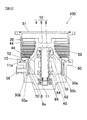
図1は、ターボ分子ポンプ100の概略構成を示す断面図である。ターボ分子ポンプ100は、真空排気部として、ターボポンプ部80と、ターボポンプ部80よりも真空排気下流側に位置するドラッグポンプ部81とを有する。ターボ分子ポンプ100のケーシング52内にはロータ組立体10が回転自在に設けられている。ロータ組立体10は、ポンプロータ4と、シャフト5と、ロータディスク6を備えている。ターボ分子ポンプ100は磁気軸受式のポンプであり、ロータ組立体10は、上部ラジアル電磁石62、下部ラジアル電磁石64、スラスト電磁石66によって非接触支持される。
-Embodiment-
FIG. 1 is a cross-sectional view showing a schematic configuration of the turbo
モータハウジング48はベース50に立設されている。モータハウジング48内には、シャフト5、上部ラジアル電磁石62、下部ラジアル電磁石64、および、後述するモータ40などが設けられている。
The
ポンプロータ4は、釣鐘形状をしており、モータハウジング48を内包するように配置されている。ポンプロータ4には、複数段のロータ翼20とロータ円筒部8とが設けられている。複数段のロータ翼20の各段の間には、それぞれステータ翼44が設けられ、これらロータ翼20とステータ翼44とによりターボポンプ部80が構成される。ロータ円筒部8の外周側にはネジステータ11が設けられ、これらの部材によりドラッグポンプ部81が構成される。ネジステータ11はアルミ合金などで形成されている。ネジステータ11は、フランジ部11aにおいてベース50にボルト15で固定されている。ネジステータ11の内周面には、ねじ溝が設けられている。一方、ロータ円筒部8の外周面には、ねじ溝が設けられていない。
The
各ステータ翼44は、スペーサ58を介してベース50上に配設されている。ケーシング52がベース50に固定されると、積層されたスペーサ58がベース50とケーシング52との間に挟持され、各ステータ翼44が位置決めされる。
Each
ベース50には排気口56が設けられている。本実施形態の排気口56およびその開口部56aは、ベース50の内部底面50aよりも吸気口31側に設けられている。そして、真空排気部に開口した、すなわち、ポンプ内部に面した排気口56の開口部56aは、ロータ円筒部8よりも外周側に位置している。この排気口56にバックポンプ(不図示)が接続される。ロータ組立体10が上部ラジアル電磁石62、下部ラジアル電磁石64、スラスト電磁石66によって磁気浮上されつつモータ40により高速回転駆動される。これにより、吸気口31から吸気した気体は、ターボポンプ部80であるロータ翼20とステータ翼44とが協働する排気動作により、また、ドラッグポンプ部81であるロータ円筒部8とネジステータ11とが協働する排気動作によりポンプ排気側空間へと移送される。ポンプ排気側空間に移送された気体は、ポンプ排気側空間に連通する排気口56に接続されたバックポンプ(不図示)により排気される。なお、ポンプ排気側空間については、図5(a)でさらに説明する。
The
ベース50の内部底面50a上には、定常回転時のロータ円筒部8の回転軸方向真空排気下流側端面(以下、単に、下流側端面という。)8aに対向する位置に、リング形状のネジ溝排気部70(図2参照)が、ネジ溝排気部70の中心をポンプロータ4の回転軸の中心に合わせるように、ネジ(不図示)で固定されている。ここで、図2(a)、(b)を用いて、ネジ溝排気部70の構造と作用について述べる。図2(a)は、ネジ溝排気部70を吸気口31側から見た図である。図2(a)には、2点鎖線でロータ円筒部8も示されている。さらに、符号8Rで示した矢印は、ロータ円筒部8の回転の向きを示している。なお、ロータ円筒部8の外周側輪郭とネジ溝排気部の外周側輪郭は対向し、ロータ円筒部8の内周側輪郭とネジ溝排気部の内周側輪郭は対向するが、見易さのため、図では、ずらして示している。ネジ溝排気部70には、複数のネジ溝71が設けられている。ネジ溝71が設けられることに伴い、凸部72も設けられる。図2(b)は、図2(a)でのA−A断面図である。図2(b)に示すように、凹部であるネジ溝71と、凸部72が周方向に交互に設けられている。ネジ溝排気部の中心から伸びる半直線78を基準にして、複数のネジ溝71のうちの一つであるネジ溝71aの傾斜について説明する。他のネジ溝71の傾斜もネジ溝71aと同様である。ネジ溝71aの外周側端部71a1は、半直線78よりもロータ円筒部8の回転の向き8R側に位置する。一方、ネジ溝71aの内周側端部71a2は半直線78よりもロータ円筒部8の回転の向き8Rと逆向きに位置している。ネジ溝71aは、外周側端部71a1と内周側端部71a2を接続する凹部である。図では、直線状に接続しているが、曲線状に接続してもよい。ネジ溝71の上をロータ円筒部8の下流側端面8aが、吸気口側から見て時計回り、すなわち、回転の向き8Rに回転することで、ポンプロータ4の外周側に気体を排気する。その結果、ポンプロータ4の内周側に気体が向かうのを防止できる。なお、このような排気機構は、シーグバーンポンプ機構と呼ばれている。
On the
図1に戻る。ネジ溝排気部70は、ベース50の内部底面50aに設けられている。ロータ円筒部8の回転時、ロータ円筒部8は、遠心力によって主に径方向に膨張する。しかし、この膨張は、回転軸方向にはほとんど影響がない。すなわち、ロータ円筒部8の回転軸方向における寸法は、ロータ円筒部8の回転時と静止時とでほとんど変化がない。よって、ロータ円筒部8の下流側端面8aとネジ溝排気部70のクリアランスは、ロータ円筒部8の回転時と静止時とで、ほとんど変化しない。そのため、たとえ、ネジ溝排気部70に反応生成物が堆積したとしても静止時のポンプロータ4(ロータ円筒部8)とネジ溝排気部70との固着は起こらない。
Returning to FIG. The thread
図5(a)を用いてさらに述べる。図5(a)は、ポンプロータ4の定常回転時におけるロータ円筒部8に対する本実施形態のネジ溝排気部70の位置を示している。なお、図5において、図示左方が外周側を示す。図5(a)に示すように、ネジ溝排気部70の外径D70aは、定常回転時のロータ円筒部8の外径D8aとほぼ等しく設定されている。
以上のようにネジ溝排気部70を設けると、ネジ溝排気部70は定常回転時のロータ円筒部8の外周側に位置しない。そして、上述したように、ポンプ内部に面した排気口56の開口部56aは、ロータ円筒部8よりも外周側に設けられている。
これによって、ロータ円筒部8とネジステータ11が協働して排気された気体が排気口56に至るまでに通過する空間であるポンプ排気側空間にネジ溝排気部70が位置することがない。そのため、ロータ円筒部8とネジステータ11が協働して排気された気体がポンプ排気側空間に流入し、排気口56に排気されるまでの排気経路P1にネジ溝排気部70が位置することがない。その結果、ネジ溝排気部70がターボ分子ポンプ100の排気性能を悪化させることがない。
This will be further described with reference to FIG. FIG. 5A shows the position of the thread
When the thread
Thus, the thread
さらに、ネジ溝排気部70の内径D70bは、定常回転時のロータ円筒部8の内径D8bと等しい。すなわち、定常回転時のロータ円筒部8の下流側端面8aとネジ溝排気部70は、正対している。これによって、ネジ溝排気部70とロータ円筒部8の下流側端面8aとで構成されるシーグバーンポンプ機構の排気性能を最大に引き出すことができる。
Furthermore, the inner diameter D70b of the thread
上述した実施形態によれば、次の作用効果が得られる。
(1)本発明によるターボ分子ポンプ100は、モータ40を有するモータハウジング48が立設されたベース50と、モータ40により回転駆動され、モータハウジング48を内包するように配置される釣鐘形状のポンプロータ4と、ポンプロータ4と協働して気体を排気するポンプステータであるステータ翼44およびネジステータ11と、を備える。ベース50は、ポンプロータ4、および、ポンプステータ(ステータ翼44およびネジステータ11)により排気された気体が流入するポンプ排気側空間と、ポンプ排気側空間に連通する排気口56と、を有する。ターボ分子ポンプ100は、釣鐘形状のポンプロータ4の回転軸方向真空排気下流側端面であるロータ円筒部8の下流側端面8aに対向するベースの内部底面50aに、回転軸を中心とするリング形状に設けられ、モータハウジング48が設けられた領域からポンプ排気側空間へ気体を排気するネジ溝71を有するネジ溝排気部70をさらに備える。ネジ溝排気部70は、ロータ円筒部8とネジステータ11によって排気された気体がポンプ排気側空間に流入し、排気口56に排気されるまでの排気経路P1外に位置している。
これによって、ネジ溝排気部70が、排気の阻害要因とならず、ターボ分子ポンプ100の排気性能を悪化させることがない。
According to the embodiment described above, the following operational effects can be obtained.
(1) A turbo-
As a result, the thread
(2)ネジ溝排気部70は、ベース50の内部底面50a上における、定常回転時のロータ円筒部8の下流側端面8aに対向する位置に、設けられている。ロータ円筒部8がネジ溝排気部70のネジ溝71の上面を回転することで、モータハウジング48側の気体が外周側に排気される排気機構が働く。
これによって、ロータ円筒部8とネジステータ11によって排気された腐食性のプロセスガスを含む気体がポンプロータ4(ロータ円筒部8)の内周側に向かわないようにすることができる。その結果、ポンプロータ4の内周側に設けられたモータハウジング48内のモータ40や磁気軸受などの腐食を防止することができる。
(2) The thread
Thereby, the gas containing the corrosive process gas exhausted by the rotor
(3)ネジ溝排気部70は、ベース50の内部底面50aに設けられている。ロータ円筒部8の回転時、ロータ円筒部8は、遠心力によって主に径方向に膨張する。しかし、この膨張は、回転軸方向にはほとんど影響がない。すなわち、ロータ円筒部8の回転軸方向における寸法は、ロータ円筒部8の回転時と静止時とでほとんど変化がない。よって、ロータ円筒部8の下流側端面8aとネジ溝排気部70のクリアランスは、ロータ円筒部8の回転時と静止時とで、ほとんど変化しない。
そのため、たとえ、ネジ溝排気部70に反応生成物が堆積したとしても静止時のポンプロータ4(ロータ円筒部8)とネジ溝排気部70との固着は起こらない。
これによって、ターボ分子ポンプ100の再起動時に、ポンプロータ4が回転できないという事態を避けることができる。
(3) The thread
Therefore, even if a reaction product accumulates on the thread
As a result, it is possible to avoid a situation in which the
(4)真空排気部に開口した排気口56の開口部56aは、ロータ円筒部8よりも外周側に設けられている。さらに、ポンプロータ4の定常回転時において、ネジ溝排気部70の外径D70aは、ロータ円筒部8の外径D8aと等しいのが好ましい。すなわち、ネジ溝排気部70は定常回転時のロータ円筒部8の外周側に位置しない。
これによって、ネジ溝排気部70は、ロータ円筒部8とネジステータ11が協働して排気された気体が排気口56に至るまでの排気経路の外に、位置することになり、ネジ溝排気部70がターボ分子ポンプ100の排気性能を悪化させることがない。
本発明と、図6に示す特許文献1に記載の発明とを対比する。図6(a)は、特許文献1の図2に相当し、図6(b)は、特許文献1の図3に相当する。符号P_refで示された経路は、気体の排気経路を示している。
特許文献1に記載の発明では、ネジ溝排気部270(特許文献1に記載の補助ネジ溝18に相当)に、貫通孔216(特許文献1に記載の排気通路16に相当)が形成されている。これによって、ネジ溝271を形成する領域が狭められてしまうので、ネジ溝排気部270の排気性能が悪化する可能性がある。
一方、本発明のターボ分子ポンプ100に設けられているネジ溝排気部70には、貫通孔216のような、ネジ溝71の形成を阻害する構成を備えない。つまり、本発明では、ネジ溝排気部70は、周方向の全周に亘って連続的にネジ溝71と凸部72とが交互に配置されている。
また、特許文献1に記載の発明では、ステータ211とロータ208によって排気された気体が排気口256に至るには、ネジ溝排気部270に設けられた貫通孔216を通過せねばならない。貫通孔216の近傍では、ロータ208(特許文献1に記載のロータ4に相当)が回転しており、ネジ溝排気部270と協働して外周側へ気体を排気している。すなわち、貫通孔216の近傍で、外周側へ気体を排気する排気機構が働いているため、貫通孔216を気体が通過するのを阻害する可能性がある。貫通孔216の外周側にはネジ溝271は形成されていないものの、内周側に形成されているネジ溝271が外周側への排気をすることは明らかであり、これが、貫通孔216を気体が通過するのを阻害する可能性がある。また、排気機構を働かせるには、ネジ溝271とロータ208が接近していなければならない。そのため、貫通孔216周辺のコンダクタンスが低下することも考えられる。
一方、本発明のターボ分子ポンプ100に設けられているネジ溝排気部70は、ロータ円筒部8とネジステータ11が協働して排気された気体がポンプ排気側空間に流入し排気口56に排気されるまでの排気経路外に位置している。その結果、外周側へ排気する排気機構が排気の阻害要因となることも、ロータ円筒部8とネジ溝排気部70とが接近していることが排気経路のコンダクタンスの低下を招くこともない。
(4) The
As a result, the screw
The present invention is compared with the invention described in
In the invention described in
On the other hand, the thread
Further, in the invention described in
On the other hand, in the thread
(5)ポンプロータ4の定常回転時において、ネジ溝排気部70の外径D70aは、ロータ円筒部8の外径D8aと等しいのが好ましく、ネジ溝排気部70の内径D70bは、定常回転時のロータ円筒部8の内径D8bと等しいことが好ましい。すなわち、定常回転時のロータ円筒部8の下流側端面8aとネジ溝排気部70は、正対しているのが好ましい。
これによって、ネジ溝排気部70とロータ円筒部8とで構成されるシーグバーンポンプ機構の排気性能を最大に引き出すことができる。
(5) At the time of steady rotation of the
Thereby, the exhaust performance of the Siegeburn pump mechanism constituted by the thread
(6)リング形状のネジ溝排気部70は、ネジでベース50の内部底面50aに固定されている。すなわち、ネジ溝排気部70は、ベース50とは別の部材である。
これによって、以下に示すように、ネジ溝の加工が容易になる。
ベース50の内部底面50aは、ベース50の内部領域に位置するため、ベース50の内部底面50aに一体的にネジ溝を形成するのは、困難である。
本実施形態では、ベース50と別の部材であるネジ溝排気部70にネジ溝71を形成するので、ベース50に一体的にネジ溝を形成するよりネジ溝の加工が容易になる。
(6) The ring-shaped thread
This facilitates the processing of the thread groove as will be described below.
Since the
In the present embodiment, since the
次のような変形も本発明の範囲内であり、変形例の一つ、もしくは複数を上述の実施形態と組み合わせることも可能である。なお、以上に示した実施形態と同様の箇所については、説明を省略する。 The following modifications are also within the scope of the present invention, and one or a plurality of modifications can be combined with the above-described embodiment. In addition, description is abbreviate | omitted about the location similar to embodiment shown above.
―変形例1―
図3を用いて、ベース50の内部底面50aの変形例について説明する。本変形例では、ロータ円筒部8の外周側に位置するベース50の内部底面50aに環状溝50bが形成されている。すなわち、ベース50の内部底面50aのうち、ロータ円筒部8とベース50の内部底面50aの対向領域よりも外周側に環状溝50bが形成されている。環状溝50bを設けることで、ロータ円筒部8とネジステータ11が協働して排気された気体が排気口56に至るまでの排気経路を拡張することになるため、コンダクタンスが向上し、ターボ分子ポンプ100の排気性能を向上することができる。
-Modification 1-
A modification of the
―変形例2―
図4を用いて、排気口56の位置の変形例について説明する。以上の実施形態では、排気口56がベース50の内部底面50aよりも吸気口31側に設けられているが、本変形例では、排気口56がベース50の内部底面50aよりもポンプ下面100a側(図示下方側)に設けられている。しかし、以上の実施形態と同様に、ポンプ内部に面した排気口56の開口部56aは、ロータ円筒部8よりも外周側に設けられている。そして、実施形態と同様に、ネジ溝排気部70は、定常回転時のロータ円筒部8の外周側に位置しない。
そのため、ネジ溝排気部70は、ロータ円筒部8とネジステータ11が協働して排気された気体が排気口56に至るまでの排気経路P2に位置することがなく、ネジ溝排気部70が排気性能を悪化させることがない。
よって、本変形例でも、以上の実施形態と同様の作用効果を奏する。
-Modification 2-
A modification of the position of the
Therefore, the thread
Therefore, this modification also has the same effects as the above embodiment.
以下に示す、変形例3と変形例4は、ネジ溝排気部70の変形例である。図5を用いて、変形例3と変形例4におけるネジ溝排気部70を、以上に示した実施形態のネジ溝排気部70と対比しながら説明する。なお、図5において、図示左方が外周側を示す。また、図5は、ポンプロータ4(ロータ円筒部8)が定常回転している時の様子を示している。
Modification 3 and
―変形例3―
図5(b)に示す本変形例のネジ溝排気部70の外径D70aは、図5(a)に示すネジ溝排気部70の外径D70aと等しい。これは、すなわち、ネジ溝排気部の外周側端部がロータ円筒部8の外周側に位置しないことを意味する。よって、ロータ円筒部8とネジステータ11が協働して排気された気体が排気口56に至るまでの排気経路P1に、ネジ溝排気部70が位置することがなく、ネジ溝排気部70がターボ分子ポンプ100の排気性能を悪化させることがない。
-Modification 3-
The outer diameter D70a of the thread
さらに、図5(b)に示す本変形例のネジ溝排気部70の内径D70bは、図5(a)に示すネジ溝排気部70の内径D70bよりも小さい。そのため、ポンプロータ4の定常回転時において、ネジ溝排気部70の内周側端部は、ロータ円筒部8の下流側端面8aの内周側端部よりも内周側に位置する。
Furthermore, the inner diameter D70b of the thread
ロータ円筒部8とネジ溝排気部70が対向しない領域は、排気する作用を有しないため、図5(b)に示すネジ溝排気部70とロータ円筒部8との排気性能は、図5(a)に示すネジ溝排気部70とロータ円筒部8との排気性能と等しくなる。
Since the region where the rotor
―変形例4―
図5(c)に示す本変形例のネジ溝排気部70の外径D70aは、図5(a)に示すネジ溝排気部70の外径D70aよりも小さい。そのため、ポンプロータ4の定常回転時において、ネジ溝排気部70の外周側端部は、ロータ円筒部8の下流側端面8aの外周側端部よりも内周側に位置する。これは、すなわち、ネジ溝排気部70の外周側端部がロータ円筒部8の外周側に位置しないことを意味する。よって、ロータ円筒部8とネジステータ11が協働して排気された気体が排気口56に至るまでの排気経路P1にネジ溝排気部70が位置することがなく、ネジ溝排気部70がターボ分子ポンプ100の排気性能を悪化させることがない。
-Modification 4-
The outer diameter D70a of the thread
さらに、図5(c)に示す本変形例のネジ溝排気部70の内径D70bは、図5(a)に示すネジ溝排気部70の内径D70bよりも大きい。そのため、ポンプロータ4の定常回転時において、ネジ溝排気部70の内周側端部は、ロータ円筒部8の下流側端面8aの内周側端部よりも外周側に位置する。
Furthermore, the inner diameter D70b of the thread
以上より、図5(c)に示すネジ溝排気部70とロータ円筒部8とが対向する面積は、図5(a)に示す対向する面積よりも小さくなるため、図5(c)に示すネジ溝排気部70とロータ円筒部8との排気性能は、図5(a)に示す以上の実施形態に示したネジ溝排気部70とロータ円筒部8との排気性能よりも低くなる。しかし、ポンプロータ4の内周側に気体が向かうことを防止できるのであれば、図5(c)に示すようなネジ溝排気部70でも問題ない。
From the above, the area where the screw
以上の実施形態および変形例3、4より、ネジ溝排気部70の外径D70aについて、以下のような条件(I)、(II)が課せられていることが理解できる。
(I)ポンプロータ4の内周側に気体が向かうのを防ぐためのネジ溝排気部70とロータ円筒部8とで排気機構を構成するには、ネジ溝排気部70とロータ円筒部8とが対向する領域が必要である。ポンプロータ4の定常回転時でネジ溝排気部70とロータ円筒部8とが対向するためには、ネジ溝排気部70の外径D70aは、ポンプロータ4の定常回転時のロータ円筒部8の内径D8bよりも大きいことが好ましい。
(II)排気口56の開口部56aがロータ円筒部8の外周側に開口されている。そのため、ポンプロータ4の定常回転時にネジ溝排気部70は、ロータ円筒部8とネジステータ11が協働して排気された気体が排気口56に至るまでの排気経路の外に位置するためには、ネジ溝排気部70の外径D70aは、ポンプロータ4の定常回転時のロータ円筒部8の外径D8a以下であることが好ましい。
From the above embodiment and
(I) In order to form an exhaust mechanism with the thread
(II) The
ネジ溝排気部70は、ベース50の内部底面50aに設けるようにしたが、ロータ円筒部8の下流側端面8aに設けるようにしてもよい。その場合、ネジ溝排気部70は、ロータ円筒部8と一体的に設けることも、ロータ円筒部8と別部材で設けることもできる。ロータ円筒部8の回転軸方向真空排気下流側端面にネジ溝排気部70を設ける場合には、以下の条件(III)、(IV)が課せられていることが理解できる。なお、これらの条件(III)、(IV)は、ポンプロータ4の定常回転時を想定している。ロータ円筒部8の下流側端面8aに設ける場合で、ポンプロータ4の定常回転時を想定するのは、ネジ溝排気部70とロータ円筒部8の膨張率の違いを考慮してのことである。
(III)ロータ円筒部8の回転軸方向真空排気下流側端面にネジ溝排気部70を設けるためには、ネジ溝排気部70の外径D70aは、ロータ円筒部8の内径D8bよりも大きく外径D8a以下であることが好ましい。
(IV)ロータ円筒部8とネジステータ11が協働して排気された気体が排気口56に至るまでの排気経路の外に位置するためには、ロータ円筒部8の下流側端面8aの外周側端部からネジ溝排気部70が突出しないようにする必要がある。すなわち、上記の(II)での結論と同様に、ネジ溝排気部70の外径D70aは、ポンプロータ4の定常回転時のロータ円筒部8の外径D8a以下であることが好ましい。
The thread
(III) In order to provide the thread
(IV) In order for the
以上で示したように、ネジ溝排気部70をベース50の内部底面50aに設ける場合でも、ロータ円筒部8の下流側端面8aに設ける場合でも、ネジ溝排気部70には、ネジ溝排気部70の外径D70aを、ポンプロータ4の定常回転時のロータ円筒部8の内径D8bよりも大きく、かつ、外径D8a以下にするのが好ましいという条件が課せられる。
As described above, the thread
ネジ溝排気部70を、ベース50の内部底面50a、および、ロータ円筒部8の下流側端面8aの両方に設けるようにしてもよい。
You may make it provide the thread
本実施形態では、ネジ溝排気部70がベース50の内部底面50aにネジで固定されているとしたが、接着剤で固定されるようにしてもよい。
In the present embodiment, the screw
本実施形態では、ネジ溝排気部70は、ベース50と別部材としたが、ベース50と一体的に設けることも可能である。
In the present embodiment, the screw
以上では、ターボポンプ部およびドラッグポンプ部を有する真空ポンプに本発明を適用したが、本発明は、以下のような真空ポンプにも適用できる。
・ターボポンプ部を有さず、ドラッグポンプ部のみを真空排気部として有する真空ポンプ、すなわち、モレキュラドラッグポンプ。
モレキュラドラッグポンプにおいては、図1に示すターボ分子ポンプ100と同様に、ネジ溝排気部を設けることができる。すなわち、ベースの内部底面のうち、ロータ円筒部の回転軸方向真空排気下流側端面に対向する領域に、ネジ溝排気部を設ければよい。
・ドラッグポンプ部を有さず、ターボポンプ部のみを真空排気部として有する真空ポンプ、すなわち、全翼タイプのターボ分子ポンプ。
図7は、全翼タイプのターボ分子ポンプ100の一部を示している。全翼タイプのターボ分子ポンプ100は、真空排気部として、複数段のロータ翼20が形成されたポンプロータ4とロータ翼20の間に配設されるステータ翼44を備えている。全翼タイプのターボ分子ポンプ100においては、ベース50の内部底面50aのうち、ポンプロータ4の回転軸方向真空排気下流側端面4aに対向する領域に、ネジ溝排気部70を設ければよい。
In the above, the present invention is applied to a vacuum pump having a turbo pump unit and a drag pump unit, but the present invention can also be applied to the following vacuum pumps.
A vacuum pump that does not have a turbo pump section and has only a drag pump section as a vacuum exhaust section, that is, a molecular drag pump.
In the molecular drag pump, a thread groove exhaust part can be provided in the same manner as the turbo
A vacuum pump that does not have a drag pump part and has only a turbo pump part as a vacuum exhaust part, that is, an all-wing type turbo molecular pump.
FIG. 7 shows a part of the all-blade type turbo
以上では、ロータ組立体を支えるための軸受として磁気軸受を備える真空ポンプに本発明を適用したが、本発明は、磁気軸受以外の軸受、例えば、転がり軸受を備える真空ポンプに適用することも可能である。 In the above, the present invention is applied to a vacuum pump including a magnetic bearing as a bearing for supporting the rotor assembly. However, the present invention can also be applied to a bearing other than the magnetic bearing, for example, a vacuum pump including a rolling bearing. It is.
本発明の真空ポンプにおいては、ステータの内周面、および、ロータ円筒部の外周面のいずれか一方に、ねじ溝を設ければよい。よって、以上では、ねじ溝が内周面に設けられたステータ、すなわち、ネジステータを用いたが、ステータの内周面にねじ溝を設ける代わりに、ロータ円筒部の外周面にねじ溝を設けることもできる。 In the vacuum pump of the present invention, a thread groove may be provided on one of the inner peripheral surface of the stator and the outer peripheral surface of the rotor cylindrical portion. Therefore, in the above, a stator having a thread groove on the inner peripheral surface, that is, a screw stator is used. Instead of providing a thread groove on the inner peripheral surface of the stator, a screw groove is provided on the outer peripheral surface of the rotor cylindrical portion. You can also.
以上では、種々の実施の形態および変形例を説明したが、本発明はこれらの内容に限定されるものではない。本発明の技術的思想の範囲内で考えられるその他の態様も本発明の範囲内に含まれる。 Although various embodiments and modifications have been described above, the present invention is not limited to these contents. Other embodiments conceivable within the scope of the technical idea of the present invention are also included in the scope of the present invention.
4:ポンプロータ、 5:シャフト、 6:ロータディスク、 8:ロータ円筒部、
10:ロータ組立体、 11:ネジステータ、 11a:フランジ部、
20:ロータ翼、 31:吸気口、 40:モータ、 44:ステータ翼、
48:モータハウジング、
50:ベース、 50a:内部底面、 50b:環状溝、
52:ケーシング、 56:排気口、 56a:開口部、
58:スペーサ、 62:上部ラジアル電磁石、
64:下部ラジアル電磁石、 66:スラスト電磁石、 70:ネジ溝排気部、
71:ネジ溝、 80:ターボポンプ部、 81:ドラッグポンプ部、
100:ターボ分子ポンプ、
8R:回転の向き、
D8a:外径、 D8b:内径、 D70a:外径、 D70b:内径、
P1、P2:排気経路
4: Pump rotor, 5: Shaft, 6: Rotor disc, 8: Rotor cylindrical part,
10: Rotor assembly, 11: Screw stator, 11a: Flange part,
20: Rotor blade, 31: Inlet port, 40: Motor, 44: Stator blade,
48: motor housing,
50: base, 50a: inner bottom surface, 50b: annular groove,
52: casing, 56: exhaust port, 56a: opening,
58: Spacer, 62: Upper radial electromagnet,
64: Lower radial electromagnet, 66: Thrust electromagnet, 70: Screw groove exhaust part,
71: Screw groove, 80: Turbo pump part, 81: Drag pump part,
100: turbo molecular pump,
8R: direction of rotation,
D8a: outer diameter, D8b: inner diameter, D70a: outer diameter, D70b: inner diameter,
P1, P2: Exhaust path
Claims (6)
前記複数段のロータ翼と交互に配置される複数段のステータ翼と、前記ロータ円筒部の外周側に所定隙間を介して囲むように設けられたステータとを有し、前記ポンプロータと協働して気体を排気するポンプステータと、
前記ポンプロータおよび前記ポンプステータにより排気された気体が流入する排気側空間と、前記排気側空間に連通する排気口とが形成されたベースと、
前記ベースの内部底面のうち、前記ロータ円筒部の下流側端面が対向する対向領域に、前記ポンプロータの回転軸を中心とするリング形状に設けられ、前記ポンプロータの内周側から前記排気側空間へ気体を排気する溝排気部とを備え、
前記溝排気部は、凹部である溝と凸部とが周方向の全周にわたって交互に連続的に配置されており、前記溝の形成を阻害する貫通孔が形成されておらず、
前記溝排気部の外径が、前記ポンプロータの定常回転時における前記ロータ円筒部の外径以下で、かつ、前記ポンプロータの定常回転時における前記ロータ円筒部の内径よりも大きく設定されていることにより、前記溝排気部は、気体が前記排気側空間に流入し前記排気口に排気されるまでの排気経路外に位置する真空ポンプ。 A pump rotor having a plurality of stages of rotor blades, and a rotor cylindrical portion provided downstream of the rotor blades, and driven to rotate;
A plurality of stages of stator blades arranged alternately with the plurality of stages of rotor blades; and a stator provided on the outer peripheral side of the rotor cylindrical portion so as to surround a predetermined gap, and cooperates with the pump rotor A pump stator for exhausting the gas,
A base formed with an exhaust side space into which gas exhausted by the pump rotor and the pump stator flows, and an exhaust port communicating with the exhaust side space;
Of the inner bottom surface of the base , a ring shape centering on the rotation axis of the pump rotor is provided in a facing region where the downstream end surface of the rotor cylindrical portion faces, and the exhaust side from the inner peripheral side of the pump rotor A groove exhaust for exhausting gas into the space,
The groove exhaust portion, the groove and the convex portion that is a concave portion is alternately and continuously arranged over the entire circumference in the circumferential direction , the through hole that inhibits the formation of the groove is not formed,
The outer diameter of the groove exhaust portion is set to be equal to or smaller than the outer diameter of the rotor cylindrical portion at the time of steady rotation of the pump rotor and larger than the inner diameter of the rotor cylindrical portion at the time of steady rotation of the pump rotor. it allows the groove pumping section, vacuum pumps gas is located outside the exhaust route to be exhausted to the exhaust port flows into the exhaust side space.
前記溝排気部を形成したリング状部材が別部材として設けられ、前記対向領域に固定されている真空ポンプ。 The vacuum pump according to claim 1, wherein
A vacuum pump in which a ring-shaped member in which the groove exhaust portion is formed is provided as a separate member and is fixed to the facing region.
前記溝排気部の外径は、前記ポンプロータの定常回転時における前記ロータ円筒部の外径とほぼ等しく、
前記溝排気部の内径は、前記ポンプロータの定常回転時における前記ロータ円筒部の内径とほぼ等しい、又は、小さい真空ポンプ。 The vacuum pump according to claim 1 or 2 ,
The outer diameter of the groove exhaust part is substantially equal to the outer diameter of the rotor cylindrical part during steady rotation of the pump rotor,
A vacuum pump in which the inner diameter of the groove exhaust portion is substantially equal to or smaller than the inner diameter of the rotor cylindrical portion during steady rotation of the pump rotor.
前記ベースの内部底面のうち、前記対向領域よりも外周側には、環状溝が設けられている真空ポンプ。 In the vacuum pump as described in any one of Claims 1-3 ,
A vacuum pump in which an annular groove is provided on the outer bottom side of the opposed region in the inner bottom surface of the base.
前記複数段のロータ翼と交互に配置される複数段のステータ翼と、前記ロータ円筒部の外周側に所定隙間を介して囲むように設けられたステータとを有し、前記ポンプロータと協働して気体を排気するポンプステータと、 A plurality of stages of stator blades arranged alternately with the plurality of stages of rotor blades; and a stator provided on the outer peripheral side of the rotor cylindrical portion so as to surround a predetermined gap, and cooperates with the pump rotor A pump stator for exhausting the gas,
前記ポンプロータおよび前記ポンプステータにより排気された気体が流入する排気側空間と、前記排気側空間に連通する排気口とが形成されたベースと、 A base formed with an exhaust side space into which gas exhausted by the pump rotor and the pump stator flows, and an exhaust port communicating with the exhaust side space;
前記ロータ円筒部の下流側端面、または、前記ベースの内部底面であって前記ロータ円筒部の前記下流側端面が対向する対向領域に、前記ポンプロータの回転軸を中心とするリング形状に設けられ、前記ポンプロータの内周側から前記排気側空間へ気体を排気する溝排気部とを備え、Provided in a ring shape with the rotation axis of the pump rotor as the center in a downstream end surface of the rotor cylindrical portion or an inner bottom surface of the base and opposed to the downstream end surface of the rotor cylindrical portion. And a groove exhaust part for exhausting gas from the inner peripheral side of the pump rotor to the exhaust side space,
前記溝排気部は、凹部である溝と凸部とが周方向に交互に配置されており、 The groove exhaust part, the grooves and convex portions that are concave portions are alternately arranged in the circumferential direction,
前記溝排気部は、気体が前記排気側空間に流入し前記排気口に排気されるまでの排気経路外に位置し、 The groove exhaust part is located outside the exhaust path until gas flows into the exhaust side space and is exhausted to the exhaust port,
前記溝排気部を形成したリング状部材が別部材として設けられ、前記ロータ円筒部の前記下流側端面、または、前記対向領域に固定されている、真空ポンプ。 A vacuum pump in which a ring-shaped member in which the groove exhaust portion is formed is provided as a separate member, and is fixed to the downstream end surface of the rotor cylindrical portion or the facing region.
前記複数段のロータ翼と交互に配置される複数段のステータ翼と、前記ロータ円筒部の外周側に所定隙間を介して囲むように設けられたステータとを有し、前記ポンプロータと協働して気体を排気するポンプステータと、 A plurality of stages of stator blades arranged alternately with the plurality of stages of rotor blades; and a stator provided on the outer peripheral side of the rotor cylindrical portion so as to surround a predetermined gap, and cooperates with the pump rotor A pump stator for exhausting the gas,
前記ポンプロータおよび前記ポンプステータにより排気された気体が流入する排気側空間と、前記排気側空間に連通する排気口とが形成されたベースと、 A base formed with an exhaust side space into which gas exhausted by the pump rotor and the pump stator flows, and an exhaust port communicating with the exhaust side space;
前記ロータ円筒部の下流側端面、または、前記ベースの内部底面であって前記ロータ円筒部の前記下流側端面が対向する対向領域に、前記ポンプロータの回転軸を中心とするリング形状に設けられ、前記ポンプロータの内周側から前記排気側空間へ気体を排気する溝排気部とを備え、Provided in a ring shape with the rotation axis of the pump rotor as the center in a downstream end surface of the rotor cylindrical portion or an inner bottom surface of the base and opposed to the downstream end surface of the rotor cylindrical portion. And a groove exhaust part for exhausting gas from the inner peripheral side of the pump rotor to the exhaust side space,
前記溝排気部は、凹部である溝と凸部とが周方向に交互に配置されており、 The groove exhaust part, the grooves and convex portions that are concave portions are alternately arranged in the circumferential direction,
前記溝排気部は、気体が前記排気側空間に流入し前記排気口に排気されるまでの排気経路外に位置し、 The groove exhaust part is located outside the exhaust path until gas flows into the exhaust side space and is exhausted to the exhaust port,
前記ベースの内部底面のうち、前記対向領域よりも外周側には、環状溝が設けられている、真空ポンプ。 A vacuum pump in which an annular groove is provided on the outer peripheral side of the opposed region in the inner bottom surface of the base.
Priority Applications (3)
| Application Number | Priority Date | Filing Date | Title |
|---|---|---|---|
| JP2014042494A JP6331491B2 (en) | 2013-12-27 | 2014-03-05 | Vacuum pump |
| US14/559,475 US9771940B2 (en) | 2013-12-27 | 2014-12-03 | Vacuum pump |
| CN201410787893.9A CN104747466B (en) | 2013-12-27 | 2014-12-17 | Vacuum pump |
Applications Claiming Priority (3)
| Application Number | Priority Date | Filing Date | Title |
|---|---|---|---|
| JP2013272207 | 2013-12-27 | ||
| JP2013272207 | 2013-12-27 | ||
| JP2014042494A JP6331491B2 (en) | 2013-12-27 | 2014-03-05 | Vacuum pump |
Publications (3)
| Publication Number | Publication Date |
|---|---|
| JP2015143513A JP2015143513A (en) | 2015-08-06 |
| JP2015143513A5 JP2015143513A5 (en) | 2017-05-25 |
| JP6331491B2 true JP6331491B2 (en) | 2018-05-30 |
Family
ID=53481196
Family Applications (1)
| Application Number | Title | Priority Date | Filing Date |
|---|---|---|---|
| JP2014042494A Active JP6331491B2 (en) | 2013-12-27 | 2014-03-05 | Vacuum pump |
Country Status (3)
| Country | Link |
|---|---|
| US (1) | US9771940B2 (en) |
| JP (1) | JP6331491B2 (en) |
| CN (1) | CN104747466B (en) |
Families Citing this family (7)
| Publication number | Priority date | Publication date | Assignee | Title |
|---|---|---|---|---|
| JP6692635B2 (en) * | 2015-12-09 | 2020-05-13 | エドワーズ株式会社 | Connectable thread groove spacer and vacuum pump |
| GB2579665B (en) * | 2018-12-12 | 2021-05-19 | Edwards Ltd | Multi-stage turbomolecular pump |
| JP7371852B2 (en) * | 2019-07-17 | 2023-10-31 | エドワーズ株式会社 | Vacuum pump |
| JP2021055673A (en) * | 2019-09-30 | 2021-04-08 | エドワーズ株式会社 | Vacuum pump |
| GB2588146A (en) * | 2019-10-09 | 2021-04-21 | Edwards Ltd | Vacuum pump |
| CN114673671B (en) * | 2020-12-25 | 2024-04-02 | 广东美的白色家电技术创新中心有限公司 | Blower and dust suction device |
| CN113997197A (en) * | 2021-10-29 | 2022-02-01 | 华海清科股份有限公司 | A main shaft assembly and base plate attenuate device for base plate attenuate |
Family Cites Families (9)
| Publication number | Priority date | Publication date | Assignee | Title |
|---|---|---|---|---|
| JPH056195A (en) | 1991-06-27 | 1993-01-14 | Nec Corp | Conversation condition display device |
| JPH056195U (en) * | 1991-07-03 | 1993-01-29 | セイコー精機株式会社 | Vacuum pump |
| JP4447684B2 (en) * | 1999-01-13 | 2010-04-07 | 株式会社島津製作所 | Turbo molecular pump |
| JP2001003890A (en) | 1999-06-23 | 2001-01-09 | Shimadzu Corp | Magnetic bearing type turbo-molecular pump |
| JP3961273B2 (en) * | 2001-12-04 | 2007-08-22 | Bocエドワーズ株式会社 | Vacuum pump |
| US7717684B2 (en) * | 2003-08-21 | 2010-05-18 | Ebara Corporation | Turbo vacuum pump and semiconductor manufacturing apparatus having the same |
| JP2005194921A (en) * | 2004-01-06 | 2005-07-21 | Boc Edwards Kk | Molecular pump |
| JP5420323B2 (en) | 2009-06-23 | 2014-02-19 | 株式会社大阪真空機器製作所 | Molecular pump |
| CN102667169B (en) * | 2009-12-11 | 2016-03-02 | 埃地沃兹日本有限公司 | The tubular fixed component of thread groove exhaust portion and use the vacuum pump of these parts |
-
2014
- 2014-03-05 JP JP2014042494A patent/JP6331491B2/en active Active
- 2014-12-03 US US14/559,475 patent/US9771940B2/en active Active
- 2014-12-17 CN CN201410787893.9A patent/CN104747466B/en active Active
Also Published As
| Publication number | Publication date |
|---|---|
| CN104747466A (en) | 2015-07-01 |
| JP2015143513A (en) | 2015-08-06 |
| US20150184666A1 (en) | 2015-07-02 |
| CN104747466B (en) | 2017-04-12 |
| US9771940B2 (en) | 2017-09-26 |
Similar Documents
| Publication | Publication Date | Title |
|---|---|---|
| JP6331491B2 (en) | Vacuum pump | |
| US9909592B2 (en) | Vacuum pump | |
| JP5738869B2 (en) | Turbo molecular pump | |
| JP2003172289A (en) | Vacuum pump | |
| JP2000274394A (en) | Turbo molecular pump | |
| JP6433812B2 (en) | Adapter and vacuum pump | |
| JP3000356B1 (en) | Vacuum pump and vacuum device | |
| JP4935509B2 (en) | Turbo molecular pump | |
| JP6390098B2 (en) | Vacuum pump | |
| JP5115622B2 (en) | Turbo molecular pump | |
| JP5577798B2 (en) | Turbo molecular pump | |
| JP2006022771A (en) | Turbo molecular pump | |
| JP2014062480A (en) | Vacuum pump and method of manufacturing the same | |
| JP2001003890A (en) | Magnetic bearing type turbo-molecular pump | |
| JP5136262B2 (en) | Rotary vacuum pump | |
| JP2525848Y2 (en) | Vacuum pump | |
| JP7424007B2 (en) | Vacuum pump | |
| WO2021010347A1 (en) | Vacuum pump | |
| JP2000110771A (en) | Turbo molecular pump | |
| JPH10299774A (en) | Magnetic bearing device | |
| JPH0710493U (en) | Turbo molecular pump | |
| JP2628351B2 (en) | Compound molecular pump | |
| JP2008240571A (en) | Turbo-molecular pump | |
| JP2008280977A (en) | Turbo molecular pump | |
| JPH0914184A (en) | Turbo-molecular pump |
Legal Events
| Date | Code | Title | Description |
|---|---|---|---|
| A621 | Written request for application examination |
Free format text: JAPANESE INTERMEDIATE CODE: A621 Effective date: 20170119 |
|
| A521 | Written amendment |
Free format text: JAPANESE INTERMEDIATE CODE: A523 Effective date: 20170403 |
|
| A977 | Report on retrieval |
Free format text: JAPANESE INTERMEDIATE CODE: A971007 Effective date: 20171020 |
|
| A131 | Notification of reasons for refusal |
Free format text: JAPANESE INTERMEDIATE CODE: A131 Effective date: 20171031 |
|
| A521 | Written amendment |
Free format text: JAPANESE INTERMEDIATE CODE: A523 Effective date: 20171226 |
|
| TRDD | Decision of grant or rejection written | ||
| A01 | Written decision to grant a patent or to grant a registration (utility model) |
Free format text: JAPANESE INTERMEDIATE CODE: A01 Effective date: 20180403 |
|
| A61 | First payment of annual fees (during grant procedure) |
Free format text: JAPANESE INTERMEDIATE CODE: A61 Effective date: 20180416 |
|
| R151 | Written notification of patent or utility model registration |
Ref document number: 6331491 Country of ref document: JP Free format text: JAPANESE INTERMEDIATE CODE: R151 |