JP6328068B2 - Water-based inkjet blanket - Google Patents
Water-based inkjet blanket Download PDFInfo
- Publication number
- JP6328068B2 JP6328068B2 JP2015052698A JP2015052698A JP6328068B2 JP 6328068 B2 JP6328068 B2 JP 6328068B2 JP 2015052698 A JP2015052698 A JP 2015052698A JP 2015052698 A JP2015052698 A JP 2015052698A JP 6328068 B2 JP6328068 B2 JP 6328068B2
- Authority
- JP
- Japan
- Prior art keywords
- transfer member
- ink
- polymer
- surface energy
- image
- Prior art date
- Legal status (The legal status is an assumption and is not a legal conclusion. Google has not performed a legal analysis and makes no representation as to the accuracy of the status listed.)
- Expired - Fee Related
Links
Images

Classifications
-
- B—PERFORMING OPERATIONS; TRANSPORTING
- B41—PRINTING; LINING MACHINES; TYPEWRITERS; STAMPS
- B41J—TYPEWRITERS; SELECTIVE PRINTING MECHANISMS, i.e. MECHANISMS PRINTING OTHERWISE THAN FROM A FORME; CORRECTION OF TYPOGRAPHICAL ERRORS
- B41J11/00—Devices or arrangements of selective printing mechanisms, e.g. ink-jet printers or thermal printers, for supporting or handling copy material in sheet or web form
- B41J11/0015—Devices or arrangements of selective printing mechanisms, e.g. ink-jet printers or thermal printers, for supporting or handling copy material in sheet or web form for treating before, during or after printing or for uniform coating or laminating the copy material before or after printing
-
- B—PERFORMING OPERATIONS; TRANSPORTING
- B41—PRINTING; LINING MACHINES; TYPEWRITERS; STAMPS
- B41J—TYPEWRITERS; SELECTIVE PRINTING MECHANISMS, i.e. MECHANISMS PRINTING OTHERWISE THAN FROM A FORME; CORRECTION OF TYPOGRAPHICAL ERRORS
- B41J2/00—Typewriters or selective printing mechanisms characterised by the printing or marking process for which they are designed
- B41J2/005—Typewriters or selective printing mechanisms characterised by the printing or marking process for which they are designed characterised by bringing liquid or particles selectively into contact with a printing material
- B41J2/0057—Typewriters or selective printing mechanisms characterised by the printing or marking process for which they are designed characterised by bringing liquid or particles selectively into contact with a printing material where an intermediate transfer member receives the ink before transferring it on the printing material
-
- B—PERFORMING OPERATIONS; TRANSPORTING
- B41—PRINTING; LINING MACHINES; TYPEWRITERS; STAMPS
- B41J—TYPEWRITERS; SELECTIVE PRINTING MECHANISMS, i.e. MECHANISMS PRINTING OTHERWISE THAN FROM A FORME; CORRECTION OF TYPOGRAPHICAL ERRORS
- B41J2/00—Typewriters or selective printing mechanisms characterised by the printing or marking process for which they are designed
- B41J2/005—Typewriters or selective printing mechanisms characterised by the printing or marking process for which they are designed characterised by bringing liquid or particles selectively into contact with a printing material
- B41J2/01—Ink jet
-
- D—TEXTILES; PAPER
- D06—TREATMENT OF TEXTILES OR THE LIKE; LAUNDERING; FLEXIBLE MATERIALS NOT OTHERWISE PROVIDED FOR
- D06M—TREATMENT, NOT PROVIDED FOR ELSEWHERE IN CLASS D06, OF FIBRES, THREADS, YARNS, FABRICS, FEATHERS OR FIBROUS GOODS MADE FROM SUCH MATERIALS
- D06M15/00—Treating fibres, threads, yarns, fabrics, or fibrous goods made from such materials, with macromolecular compounds; Such treatment combined with mechanical treatment
- D06M15/19—Treating fibres, threads, yarns, fabrics, or fibrous goods made from such materials, with macromolecular compounds; Such treatment combined with mechanical treatment with synthetic macromolecular compounds
-
- B—PERFORMING OPERATIONS; TRANSPORTING
- B41—PRINTING; LINING MACHINES; TYPEWRITERS; STAMPS
- B41J—TYPEWRITERS; SELECTIVE PRINTING MECHANISMS, i.e. MECHANISMS PRINTING OTHERWISE THAN FROM A FORME; CORRECTION OF TYPOGRAPHICAL ERRORS
- B41J2/00—Typewriters or selective printing mechanisms characterised by the printing or marking process for which they are designed
- B41J2/005—Typewriters or selective printing mechanisms characterised by the printing or marking process for which they are designed characterised by bringing liquid or particles selectively into contact with a printing material
- B41J2/01—Ink jet
- B41J2002/012—Ink jet with intermediate transfer member
-
- Y—GENERAL TAGGING OF NEW TECHNOLOGICAL DEVELOPMENTS; GENERAL TAGGING OF CROSS-SECTIONAL TECHNOLOGIES SPANNING OVER SEVERAL SECTIONS OF THE IPC; TECHNICAL SUBJECTS COVERED BY FORMER USPC CROSS-REFERENCE ART COLLECTIONS [XRACs] AND DIGESTS
- Y10—TECHNICAL SUBJECTS COVERED BY FORMER USPC
- Y10T—TECHNICAL SUBJECTS COVERED BY FORMER US CLASSIFICATION
- Y10T442/00—Fabric [woven, knitted, or nonwoven textile or cloth, etc.]
- Y10T442/20—Coated or impregnated woven, knit, or nonwoven fabric which is not [a] associated with another preformed layer or fiber layer or, [b] with respect to woven and knit, characterized, respectively, by a particular or differential weave or knit, wherein the coating or impregnation is neither a foamed material nor a free metal or alloy layer
- Y10T442/2861—Coated or impregnated synthetic organic fiber fabric
Landscapes
- Engineering & Computer Science (AREA)
- Textile Engineering (AREA)
- Ink Jet (AREA)
Description
本開示は、一般的に、インクジェット転写固定装置および方法に関する。特に、本明細書には、インクジェットプリンタにおける水性ラテックスインクの濡れ能および剥離能を高める組成物が開示される。 The present disclosure relates generally to inkjet transfer fixing devices and methods. In particular, disclosed herein is a composition that enhances the wettability and peelability of aqueous latex inks in inkjet printers.
液体インクまたは溶融した固体インクがインク放出口(例えば、ノズル、スリットおよび多孔性膜)から放出されるインクジェットシステムは、例えば、粒径が小さく、低コストであるという特徴に起因して、多くのプリンタで用いられている。それに加え、インクジェットプリンタは、紙基材だけではなく、例えば、繊維製品、ゴムなどの種々の他の基材にも印刷することができる。 Inkjet systems in which liquid ink or melted solid ink is ejected from ink outlets (eg, nozzles, slits and porous membranes) have many features, for example due to their small particle size and low cost Used in printers. In addition, inkjet printers can print not only on paper substrates, but also on various other substrates such as textiles, rubber, and the like.
印刷プロセス中、種々の中間媒体(例えば、転写ベルト、中間ブランケットまたはドラム)を使用し、生成した画像を最終基材に転写してもよい。中間転写固定プロセスでは、水性ラテックスインクを、転写部材または中間ブランケットにインク放出し、熱または流れる空気またはその両方を用い、インク膜を乾燥させる。その後、乾燥した画像を最終的な紙基材に転写固定する。このプロセスを適切に行うために、転写部材またはブランケットは、2つの矛盾する要求事項を満たさなければならない。第1の要求事項は、転写部材にインクを十分に広げなければならないことであり、第2の要求事項は、乾燥させた後に、ブランケットからインクを剥離すべきことである。水性インクが大量の水を含むため、このようなインク組成物は、高エネルギー(すなわち、40mJ/m2より大きい)親水性基材に非常によく濡れ、広がる。しかし、このような基材への高い親和性に起因して、水性インクは、これらの基材から十分に剥離しない。低い表面エネルギー(すなわち、約20mJ/m2以下)を有するシリコーンゴムは、この剥離の問題から逃れられる。しかし、シリコーンゴムの主な欠点は、水に対する親和性が低いため、これらの基材にインクが濡れず、広がらないことである。したがって、転写固定プロセスに理想的な転写部材は、良好な品質の画像を生成するような最適な広がりと、紙に対し、画像を転写固定させるための最適な剥離特性とを有するだろう。ある解決策、例えば、インクに界面活性剤を添加し、インクの表面張力を下げることが提案されているが、これらの解決策には、さらなる問題がある。例えば、界面活性剤によって、インクの制御できない広がりが生じ、1ピクセルの線の縁が望ましくないほど波形になる。さらに、水性印刷ヘッドは、良好な吐出性能を満たさなければならない特定の最小表面張力の要求がある(すなわち、20mN/mより大きい)。 During the printing process, various intermediate media (eg, transfer belt, intermediate blanket or drum) may be used to transfer the resulting image to the final substrate. In the intermediate transfer fixing process, the aqueous latex ink is ejected onto a transfer member or intermediate blanket and the ink film is dried using heat and / or flowing air. Thereafter, the dried image is transferred and fixed to the final paper substrate. In order to perform this process properly, the transfer member or blanket must meet two conflicting requirements. The first requirement is that the ink must be sufficiently spread on the transfer member, and the second requirement is that the ink should be peeled from the blanket after drying. Such ink compositions wet and spread very well on high energy (ie, greater than 40 mJ / m 2 ) hydrophilic substrates because aqueous inks contain large amounts of water. However, due to such high affinity for substrates, water-based inks do not peel sufficiently from these substrates. Silicone rubbers with low surface energy (ie, less than about 20 mJ / m 2 ) escape this exfoliation problem. However, the main drawback of silicone rubber is that the ink does not wet or spread on these substrates due to its low affinity for water. Thus, an ideal transfer member for the transfer fixing process will have optimal spread to produce a good quality image and optimal release characteristics to transfer and fix the image to paper. Although some solutions have been proposed, such as adding surfactants to the ink to lower the surface tension of the ink, these solutions have additional problems. For example, surfactants cause uncontrollable spreading of the ink, resulting in an undesirably corrugated 1 pixel line edge. In addition, aqueous print heads have certain minimum surface tension requirements (ie, greater than 20 mN / m) that must meet good ejection performance.
したがって、転写固定プロセスにおいて直面する上の問題に対処するために、水性インクに望ましい広がり性および剥離特性を与える手法が必要である。 Therefore, there is a need for a technique that provides desirable spreading and release characteristics to aqueous inks to address the problems encountered in the transfer fixing process.
本明細書には、水系インクジェットプリンタに使用するための転写部材が開示される。転写部材は、不織ポリマー繊維マトリックスと、不織ポリマー繊維マトリックス全体に分散したポリマーとを含む。ポリマー繊維マトリックスは、第1の表面エネルギーを有し、ポリマーは、第2の表面エネルギーを有する。第1の表面エネルギーと第2の表面エネルギーの差は、約30mJ/m2〜約5mJ/m2である。 The present specification discloses a transfer member for use in a water-based inkjet printer. The transfer member includes a non-woven polymer fiber matrix and a polymer dispersed throughout the non-woven polymer fiber matrix. The polymer fiber matrix has a first surface energy and the polymer has a second surface energy. The difference between the first surface energy and the second surface energy is about 30 mJ / m 2 to about 5 mJ / m 2 .
転写部材を備えるインクジェットプリンタが提供される。転写部材は、不織ポリマー繊維マトリックス全体に分散したポリマーを含む。ポリマー繊維マトリックスは、第1の表面エネルギーを有し、ポリマーは、第2の表面エネルギーを有する。第1の表面エネルギーと第2の表面エネルギーの差は、約30mJ/m2〜約5mJ/m2である。インクジェットプリンタは、転写部材表面に水性インク液滴を放出してインク画像を作成するための転写部材に隣接した印刷ヘッドを備える。インクジェットプリンタは、前記転写部材に隣接し、前記印刷ヘッドの下流にある転写固定ステーションを含む。転写固定ステーションは、転写固定ステーションで転写部材とともに転写固定爪を形成する。インクジェットプリンタは、記録媒体を転写固定爪に運ぶための輸送デバイスを含み、インク画像が記録媒体に転写され、固定される。 An ink jet printer comprising a transfer member is provided. The transfer member includes a polymer dispersed throughout the nonwoven polymer fiber matrix. The polymer fiber matrix has a first surface energy and the polymer has a second surface energy. The difference between the first surface energy and the second surface energy is about 30 mJ / m 2 to about 5 mJ / m 2 . Inkjet printers include a print head adjacent to a transfer member for discharging aqueous ink droplets onto the surface of the transfer member to create an ink image. The ink jet printer includes a transfer fixing station adjacent to the transfer member and downstream of the print head. The transfer fixing station forms a transfer fixing claw together with the transfer member at the transfer fixing station. The ink jet printer includes a transport device for transporting the recording medium to the transfer fixing claw, and the ink image is transferred to the recording medium and fixed.
本明細書には、水系インクジェットプリンタに使用するための転写部材が開示される。転写部材は、不織ポリマー繊維マトリックスと、不織ポリマー繊維マトリックス全体に分散したポリマーと、不織ポリマーマトリックスの繊維に沿って均一に分散した導電性粒子とを含む。ポリマー繊維マトリックスは、第1の表面エネルギーを有し、ポリマーは、第2の表面エネルギーを有する。第1の表面エネルギーと第2の表面エネルギーの差は、約30mJ/m2〜約5mJ/m2である。 The present specification discloses a transfer member for use in a water-based inkjet printer. The transfer member includes a non-woven polymer fiber matrix, a polymer dispersed throughout the non-woven polymer fiber matrix, and conductive particles uniformly distributed along the fibers of the non-woven polymer matrix. The polymer fiber matrix has a first surface energy and the polymer has a second surface energy. The difference between the first surface energy and the second surface energy is about 30 mJ / m 2 to about 5 mJ / m 2 .
添付する図面は、本明細書に組み込まれ、本明細書の一部を構成するが、本教示のいくつかの実施形態を示し、本記載とともに、本教示の原理を説明するのに役立つ。 The accompanying drawings, which are incorporated in and constitute a part of this specification, illustrate some embodiments of the present teachings and, together with the description, serve to explain the principles of the present teachings.
厳格な構造の正確さ、詳細および縮尺を維持するのではなく、図面のいくつかの詳細を単純化し、実施形態を理解しやすくするように描かれることを注記すべきである。 It should be noted that rather than maintaining strict structural accuracy, details and scale, some details of the drawings are drawn to simplify and facilitate the understanding of the embodiments.
本教示の実施形態を詳細に参照し、その例は、添付の図面に示される。可能な場合はどれも、図面全体で同じ部品または同様の部品を指すために同じ参照番号が使用される。 Reference will now be made in detail to embodiments of the present teachings, examples of which are illustrated in the accompanying drawings. Wherever possible, the same reference numbers will be used throughout the drawings to refer to the same or like parts.
以下の記載では、記載の一部を形成する添付の図面を参照し、本教示を実施し得る具体的で例示的な実施形態を示すことによって示される。これらの実施形態を、当業者が本教示を実施することができるように十分に詳細に記載し、他の実施形態を利用してもよく、本教示の範囲を逸脱することなく変更を行ってもよいことが理解されるべきである。したがって、以下の記載は単なる例示である。 In the following description, reference is made to the accompanying drawings that form a part hereof, and in which is shown by way of specific illustrative embodiments in which the present teachings may be practiced. These embodiments are described in sufficient detail to enable those skilled in the art to practice the present teachings, other embodiments may be utilized, and modifications may be made without departing from the scope of the present teachings. It should be understood that Accordingly, the following description is merely exemplary.
1つ以上の実施例の観点で示してきたが、添付の特許請求の範囲の精神および範囲から逸脱することなく、示されている実施例に対し、変更および/または改変を行ってもよい。それに加え、具体的な特徴が、いくつかの実施例の1つのみに対して開示されていてもよいが、このような特徴を、所望なように、任意の所与の機能または具体的な機能に有利な他の実施例の1つ以上の他の特徴と組み合わせてもよい。さらに、「〜を含む(including)」、「含む(include)」、「〜を有する(having)」、「有する(has)」、「伴う(with)」という用語またはこれらの変形語をいずれかの詳細な記載および特許請求の範囲に使用する程度まで、このような用語は、「〜を含む(comprising)」という語句と同様の様式で包括的であることを意図している。「〜の少なくとも1つ」という用語は、列挙した項目の1つ以上が選択可能であることを意味するために用いられる。 While shown in terms of one or more embodiments, changes and / or modifications may be made to the illustrated embodiments without departing from the spirit and scope of the appended claims. In addition, although specific features may be disclosed for only one of several embodiments, such features may be applied to any given function or specific as desired. It may be combined with one or more other features of other embodiments advantageous in function. In addition, any of the terms “including”, “include”, “having”, “has”, “with” or variations thereof are either To the extent used in the detailed description and claims, such terms are intended to be inclusive in a manner similar to the phrase “comprising”. The term “at least one of” is used to mean that one or more of the listed items is selectable.
本実施形態の広い範囲を記載する数値範囲およびパラメータは概算値であるが、具体例に記載する数値範囲は、可能な限り正確に報告している。しかし、いかなる数値範囲も、それぞれの試験測定でみられる標準偏差から必然的に生じる特定の誤差を固有に含む。さらに、本明細書に開示するすべての範囲は、その範囲に包含される任意の部分範囲およびあらゆる部分範囲を包含することが理解されるべきである。例えば、「10未満」という範囲は、最小値が0であり、最大値が10である(境界値を含む)任意の部分範囲およびあらゆる部分範囲、すなわち、最小値が0以上であり、最大値が10以下である任意の部分範囲およびあらゆる部分範囲(例えば、1〜5)を含んでいてもよい。特定の場合には、パラメータとして述べられるような数値は、負の値であってもよい。この場合、「10未満」であると述べられる値の例は、負の値、例えば、−1、−2、−3、−10、−20、−30などを想定することができる。 The numerical ranges and parameters describing the wide range of this embodiment are approximate values, but the numerical ranges described in the specific examples are reported as accurately as possible. Any numerical range, however, inherently contains certain errors necessarily resulting from the standard deviation found in their respective testing measurements. Moreover, all ranges disclosed herein are to be understood to encompass any and all subranges subsumed within that range. For example, a range of “less than 10” is any subrange and any subrange (including the boundary value) where the minimum value is 0 and the maximum value is 10, that is, the minimum value is 0 or more and the maximum value May include any subrange and any subrange (e.g., 1-5) that is 10 or less. In certain cases, numerical values as described as parameters may be negative values. In this case, an example of a value described as “less than 10” can assume a negative value, for example, −1, −2, −3, −10, −20, −30, and the like.
「印刷ヘッド」という用語は、本明細書で使用する場合、画像受け入れ表面にインク液滴を放出するためのインクジェット放出部を備えるように構成されたプリンタ内の要素を指す。典型的な印刷ヘッドは、インクジェット放出部のアクチュエータを操作する発射シグナルに応答し、画像受け入れ表面に1種類以上のインク色の液滴を放出する複数のインクジェット放出部を備えている。インクジェットは、1つ以上の列および行に並ぶように配列する。ある実施形態では、インクジェットを、印刷ヘッドの面に沿って千鳥状の斜めになった列に配列する。種々の実施形態のプリンタは、画像受け入れ表面にインク画像を作成する1つ以上の印刷ヘッドを備えている。ある実施形態のプリンタは、印刷ゾーンに配列された複数の印刷ヘッドを備えている。インク画像を保有する画像受け入れ表面(例えば、印刷媒体または中間部材表面)は、印刷ゾーンの処理方向に印刷ヘッドが通過するように移動する。印刷ヘッド中のインクジェットは、画像受け入れ表面を横切る処理方向に垂直の処理方向を横切る方向に、インク液滴を列になるように放出する。 The term “print head” as used herein refers to an element in a printer that is configured to include an inkjet ejector for ejecting ink droplets onto an image receiving surface. A typical printhead includes a plurality of inkjet emitters that emit one or more ink-colored droplets on an image receiving surface in response to a firing signal operating an actuator of the inkjet emitter. The ink jets are arranged in one or more columns and rows. In some embodiments, the inkjets are arranged in staggered rows along the printhead surface. Various embodiments of the printer include one or more print heads that create an ink image on the image receiving surface. The printer of an embodiment includes a plurality of print heads arranged in a print zone. An image receiving surface (e.g., print media or intermediate member surface) carrying an ink image moves so that the print head passes in the processing direction of the print zone. The ink jet in the print head emits ink droplets in rows in a direction across the processing direction perpendicular to the processing direction across the image receiving surface.
直接的なプリンタでは、印刷ヘッドは、インク液滴を印刷媒体(例えば、紙シートまたは連続的な媒体ウェブ)に直接放出する。インク液滴を印刷媒体に印刷した後、プリンタは、インク液滴および印刷媒体に対して圧力を加え、場合により熱を加える2つのローラーの間に作られた爪を介して印刷媒体を移動する。1つのローラーは、典型的には、「スプレッダローラー」と呼ばれ、印刷媒体の印刷側と接触する。第2のローラーは、典型的には、「加圧ローラー」と呼ばれ、スプレッダローラーに対して媒体を押し付け、インク液滴を広げ、インクを印刷媒体に固定する。 In a direct printer, the print head ejects ink droplets directly onto a print medium (eg, a paper sheet or continuous media web). After printing the ink droplets on the print media, the printer moves the print media through a nail created between two rollers that applies pressure to the ink droplets and the print media and optionally applies heat. . One roller is typically referred to as a “spreader roller” and contacts the printing side of the print media. The second roller is typically referred to as the “pressure roller” and presses the media against the spreader roller to spread the ink droplets and fix the ink to the print media.
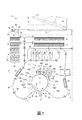
図1は、高速水性インク画像製造機またはプリンタ10を示す。示されているように、プリンタ10は、転写部材12(ブランケットまたは受け入れ部材または画像作成部材とも呼ばれる)の表面にインク画像を生成し、次いで、転写部材12を用いて作られる爪18を通過する媒体にインク画像を転写する間接的なプリンタである。プリンタ10は、以下に記載する直接的または間接的に動くサブシステムおよび要素を支えるフレーム11を備える。プリンタ10は、ドラムの形態で示される転写部材12を含むが、支持されている終端のないベルトとして構成されていてもよい。転写部材12は、外側表面21を有する。外側表面21は、方向16に移動可能であり、その上でインク画像が作られる。方向17に回転可能な転写固定ローラー19は、転写部材12の表面21に装填され、転写固定爪18を形成し、その中で、表面21に作られたインク画像が、媒体シート49に転写固定される。
FIG. 1 shows a high speed aqueous ink image making machine or
転写部材12またはブランケットは、爪18において、転写部材12の表面21から媒体シート49へのインク画像の転写を容易にするために、表面エネルギーが比較的低い材料から作られる。このような材料を以下にさらに詳細に記載する。表面管理ユニット(SMU)92は、インク画像を媒体シート49に転写した後、ブランケット21の表面に残った残留インクを除去する。
The
SMU92は、固定された容積のコーティング材料を含む容器と弾性供与ローラーとを含むコーティングアプリケータを備えていてもよく、平坦であってもよく、または多孔性であってもよく、コーティング材料と接触させるために、容器に回転可能に取り付けられている。供与ローラーは、アニロックスのような材料から作られるエラストマーローラーであってもよい。コーティング材料をブランケット21の表面に塗布し、ブランケット表面に薄層を作成する。SMU92は、以下にさらに詳細に記載するコントローラ80に操作可能に接続しており、コントローラが、供与ローラー、計量ブレードおよびクリーニングブレードを選択的に操作し、ブランケット表面にコーティング材料を堆積させ、分布させ、ブランケットまたは転写部材12の表面21から、転写されなかったインクピクセルを除去することができる。
The
一般的な記載を続けると、プリンタ10は、転写部材12が回転してセンサを通過するにつれて、転写部材12の表面21および表面21に塗布されたコーティングから反射した光を検出するように構成された光学センサ94A(イメージオンドラム(「IOD」)センサとしても知られる)を備えている。光学センサ94Aは、転写部材12の表面21を横切る方向に整列した個々の光学検出器が列になった線状の配列を含む。光学センサ94Aは、表面21から反射した光に対応するデジタル画像データを作成する。光学センサ94Aは、転写部材12が方向16に回転し、光学センサ94Aを通るにつれて、「スキャンライン」と呼ばれる一列の画像データを作成する。一実施形態では、光学センサ94Aのそれぞれの光学検出器は、さらに、赤色、緑色および青色(RGB)の反射光の色に対応する光の波長に感受性の3つの検知要素を含む。また、光学センサ94Aは、表面21に赤色、緑色および青色に輝く照射源を含む。光学センサ94Aは、画像受け入れ表面で相補的な色の光が輝き、それぞれの光検出器でRGB要素を用い、異なるインク色を検出することができる。光学センサ94Aによって作られる画像データを、プリンタ10内のコントローラ80または他のプロセッサによって分析し、表面21にあるインク画像および濡れ性を高めるコーティング(以下にさらに詳細に記載する)の厚みおよび被覆面積を特定する。ブランケット表面およびコーティングからの鏡面反射光または拡散光の反射から、厚みおよび被覆を特定することができる。他の光学センサ(例えば、94B、94Cおよび94D)は、類似の構成であり、印刷プロセス中の他のパラメータ、例えば、インクジェットの欠けまたは動作不能、および画像乾燥前のインク画像の作成(94B)、画像転写のためのインク画像の処理(94C)およびインク画像の転写効率(94D)を特定し、評価するために、表面21の周囲の異なる位置に配置されていてもよい。または、ある実施形態は、媒体での画質を評価するために使用可能なさらなるデータを作成するために、光学センサを備えていてもよい(94E)。
Continuing the general description, the
プリンタ10は、表面21が、印刷ヘッドモジュール34A〜34Dによって作られる印刷ゾーンに入る直前の位置で、転写部材12の表面21の次に位置する表面エネルギーアプリケータ120をさらに備えていてもよい。表面エネルギーアプリケータ120は、例えば、コロナ放電ユニット、酸素プラズマユニットまたは電子ビームユニットであってもよい。表面エネルギーアプリケータ120は、アプリケータ120と表面21との間に、この2つの構造の間にある空気をイオン化するのに十分な電場を放出し、負に帯電した粒子、正に帯電した粒子、または正および負に帯電した粒子の組み合わせを表面21または転写部材に塗布するような構成である。電場および帯電した粒子は、ブランケット表面の表面エネルギーを高め、以下にさらに詳細に記載する。表面21または転写部材12の表面エネルギーを高めると、その後に、モジュール34A〜34Dの印刷ヘッドによってインク液滴を放出し、表面21または転写部材12に付着させ、融着させることができる。
The
プリンタ10は、印刷ゾーンへの空気の流れを作り出し、制御する空気流管理システム100を備えている。空気流管理システム100は、印刷ヘッド空気供給部104と、印刷ヘッド空気戻り部108とを備える。印刷ヘッド空気供給部104と戻り部108は、プリンタ10のコントローラ80またはある種の他のプロセッサに操作可能に接続され、コントローラが、印刷ゾーンへ流れる空気を管理することができる。この空気流の制御によって、インク中の蒸発した溶媒および水が印刷ヘッド上で凝集するのを防ぐのに役立ち、印刷ゾーン中の熱を弱め、インクジェット内でインクが乾燥し、インクジェットが詰まり得る可能性を減らすのに役立つ。空気流管理システム100は、さらに、印刷ゾーンの湿度および温度を検出するためのセンサを備えていてもよく、空気供給部104および戻り部108をもっと正確に制御することができ、印刷ゾーン内の最適条件を確保することができる。プリンタ10内のコントローラ80またはある種の他のプロセッサは、さらに、画像領域のインク被覆に関し、システム100の制御を可能にしてもよく、または時間までは、画像が印刷されないときに空気のみが印刷ゾーンを通って流れるように、システム100の操作を可能にしてもよい。
The
高速水系インクプリンタ10は、さらに、ある色の水系インクの少なくとも1つの供給源22を含む水系インク供給および運搬サブシステム20を備える。示されているプリンタ10が、多色画像製造機であるため、インクを運搬するシステム20は、4種類の異なる色CYMK(シアン、イエロー、マゼンタ、ブラック)の水系インクをあらわす4種類の供給源22、24、26、28を備える。図1の実施形態では、印刷ヘッドシステム30は、印刷ヘッド支持部32を備えており、プリントボックスユニット(34A〜34D)としても知られる複数の印刷ヘッドモジュールを支える。それぞれの印刷ヘッドモジュール34A〜34Dは、中間転写部材12の幅方向にわたって効果的に延び、表面21にインク液滴を放出する。印刷ヘッドモジュールは、1個の印刷ヘッドまたは千鳥状の配列に構成された複数の印刷ヘッドを備えていてもよい。それぞれの印刷ヘッドモジュールは、フレーム(図示せず)に操作可能に接続し、インク液滴を放出するように整列し、表面21の上にインク画像を作成する。印刷ヘッドモジュール34A〜34Dは、1つ以上の印刷ヘッドにインクを供給するために、関連する電子機器、インク容器およびインク経路を備えていてもよい。示した実施形態において、経路(図示せず)は、印刷ヘッドモジュール34A〜34Dに供給源22、24、26および28を操作可能に接続し、モジュール内の1つ以上の印刷ヘッドにインクを供給する。一般的によく知られているように、印刷ヘッドモジュール内の1つ以上の印刷ヘッドは、それぞれ、1色のインクを放出することができる。他の実施形態では、印刷ヘッドは、2色以上のインクを放出するように構成されていてもよい。例えば、モジュール34Aおよび34B中の印刷ヘッドは、シアンおよびマゼンタのインクを放出することができ、一方、モジュール34Cおよび34D中の印刷ヘッドは、イエローおよびブラックのインクを放出することができる。示されているモジュール中の印刷ヘッドは、モジュールによって印刷されるそれぞれの色の分離解像度を高めるために、互いに相殺する(すなわち、千鳥状の)2つの並びに配列される。このような配列によって、たった1色のインクのみを放出する印刷ヘッドの1つの並びを有する印刷システムのみの解像度の2倍で印刷することができる。プリンタ10は、4個の印刷ヘッドモジュール34A〜34Dを備えているが、それぞれ、2つの印刷ヘッドの並びを有し、交互に並ぶ構造は、異なる数の印刷ヘッドモジュールを有するか、またはモジュール内の並びを有する。
The high speed
表面21の上に印刷される画像が印刷ゾーンから出た後、画像が、画像乾燥部130の下を通る。画像乾燥部130は、赤外線ヒーター134、温風源136および空気戻り部138Aおよび138Bを備える。赤外線型ヒーター134は、転写部材12の表面21に印刷した画像に赤外熱をあて、インク中の水または溶媒を蒸発させる。温風源136は、インクに温風を向かわせ、インクからの水または溶媒の蒸発を補助する。次いで、空気を集め、戻り部138Aおよび138Bによって排気し、印刷領域中の空気の流れと他の要素との干渉を減らす。
After the image to be printed on the
さらに示されるように、プリンタ10は、記録媒体を供給し、取り扱うシステム40を備え、例えば、種々の大きさの紙媒体シートの1つ以上の積み重ねを保存する。記録媒体を供給し、取り扱うシステム40は、例えば、シートまたは基材の供給源42、44、46および48を備える。プリンタ10の実施形態では、供給源48は、例えば、切断した印刷媒体シート49の形態で画像受け入れ基材を保存し、供給するための高容量紙供給部またはフィーダである。記録媒体を供給し、取り扱うシステム40は、さらに、基材を取り扱い、輸送するシステム50を備え、媒体プレコンディショナアセンブリ52と媒体ポストコンディショナアセンブリ54とを有する。プリンタ10は、印刷媒体が転写固定爪18を通った後、印刷媒体にさらなる熱および圧力を加えるための任意要素の融合デバイス60を備える。一実施形態では、融合デバイス60は、印刷媒体の上に作られる印刷画像の光沢度を調整する。図1の実施形態では、プリンタ10は、書類保持トレイ72と、書類シートを供給し、回復するデバイス74と、書類を露出させ、スキャンするシステム76とを含む元々の書類フィーダ70を備える。
As further shown, the
機械またはプリンタ10の種々のサブシステム、要素および機能の操作および制御は、コントローラまたは電子サブシステム(ESS)80の助けを借りて行われる。ESSまたはコントローラ80は、画像受け入れ部材12、印刷ヘッドモジュール34A〜34D(したがって、印刷ヘッド)、基材を供給し、取り扱うシステム40、基材を取り扱い、輸送するシステム50、ある実施形態では、1つ以上の光学センサ94A〜94Eに操作可能に接続する。ESSまたはコントローラ80は、例えば、中央処理ユニット(CPU)82を含む自己内蔵型の専用のミニコンピュータであり、電子記憶部84およびディスプレイまたはユーザインターフェース(UI)86を備える。ESSまたはコントローラ80は、例えば、センサ入力部および制御回路88と、ピクセルの配置および制御回路89とを含む。それに加え、CPU82は、画像入力源、例えば、スキャンシステム76、またはオンラインまたはワークステーションの接続90および印刷ヘッドモジュール34A〜34Dの間の画像データフローを読み取り、捕捉し、作成し、管理する。このように、ESSまたはコントローラ80は、以下に記載する印刷プロセスを含む他の機械サブシステムおよび機能のすべてを操作し、制御するための主なマルチタスクプロセッサである。
The operation and control of the various subsystems, elements and functions of the machine or
コントローラ80は、プログラム化された命令を実行する汎用または特殊用途用のプログラム制御可能なプロセッサで実行することができる。プログラム制御された機能を発揮するのに必要な命令およびデータを、プロセッサまたはコントローラに関連するメモリに保存することができる。プロセッサ、そのメモリおよびインターフェース回路は、以下に記載する操作を行うためのコントローラを構成する。これらの要素は、印刷配線回路カードで与えられてもよく、または特定用途向け集積回路(ASIC)の回路として与えられてもよい。それぞれの回路は、別個のプロセッサを用いて実行されてもよく、または複数の回路が同じプロセッサで実行されてもよい。または、回路を別個の要素で実行してもよく、または超大規模集積(VLSI)回路で与えられる回路で実行してもよい。また、本明細書に記載する回路は、プロセッサ、ASIC、別個の要素またはVLSI回路の組み合わせで実行することができる。
The
操作中に、印刷ヘッドモジュール34A〜34Dに対する印刷ヘッド制御シグナルの出力を処理し、作成するために、作成すべき画像のための画像データは、スキャンするシステム76から、またはオンラインまたはワークステーションの接続90によってコントローラ80に送られる。さらに、コントローラ80は、例えば、ユーザインターフェース86を介するオペレータの入力から、関連するサブシステムおよび要素の制御を決定し、および/または受け入れ、したがって、このような制御を実行する。結果として、適切な色のための水性インクを印刷ヘッドモジュール34A〜34Dに運ぶ。さらに、表面21に対し、ピクセルの配置制御が行われ、画像データおよび媒体(媒体シート49の形態であってもよい)に対応するインク画像を作成し、供給源42、44、46、48のいずれかによって供給され、爪18にタイミングよく運ぶために、記録媒体輸送システム50によって取り扱われる。爪18において、インク画像は、転写部材12の表面21から、転写固定爪18の媒体基材に転写される。
During operation, image data for the image to be created is processed from the
ある印刷操作において、1つのインク画像が、表面21全体を覆ってもよく(シングルピッチ)、または複数のインク画像が、表面21に堆積してもよい(マルチピッチ)。マルチピッチ印刷構造において、転写部材12(画像受け入れ部材とも呼ばれる)の表面21は、複数のセグメントに分けられていてもよく、それぞれのセグメントが、書類ゾーンの全ページ画像(すなわち、シングルピッチ)および表面21に作られる複数のピッチに分けられる書類内のゾーンを含む。例えば、2ピッチの画像受け入れ部材は、表面21の周囲に2つの書類内ゾーンによって分けられる2つの書類ゾーンを含む。同様に、例えば、4ピッチの画像受け入れ部材は、4つの書類ゾーンを含み、それぞれ、表面21を通過または一巡りする間に1つの媒体シートに作られるインク画像に対応する。
In certain printing operations, one ink image may cover the entire surface 21 (single pitch), or multiple ink images may be deposited on the surface 21 (multi-pitch). In a multi-pitch printing structure, the
1つ以上の画像が、コントローラ80の制御下、表面に作られたら、図示したインクジェットプリンタ10は、プリンタ内の要素を操作し、表面21から媒体へ1つ以上の画像を転写し、固定するためのプロセスを行う。プリンタ10では、コントローラ80は、媒体輸送システム50中の1つ以上のローラー64を動かすためのアクチュエータを操作し、媒体シート49を処理方向Pに転写固定ローラー19に隣接する位置まで移動させ、次いで、転写固定ローラー19と転写部材12の表面21の間にある転写固定爪18を通って移動する。転写固定ローラー19は、転写部材12の表面21に対し、媒体シート49の前側を押すために、媒体シート49の裏側に対して圧力を加える。転写固定ローラー19も加熱してもよいが、図1の実施形態では、転写固定ローラー19は加熱されない。その代わりに、媒体シート49のための媒体プレコンディショナアセンブリ52が、爪に向かう媒体の経路に与えられる。媒体プレコンディショナアセンブリ52は、媒体シート49を所定の温度に慣らし、画像を媒体に転写するのを助け、それによって、転写固定ローラーのデザインを単純化する。加熱した媒体シート49の裏側に対し、転写固定ローラー19によって作られる圧力は、転写部材12から媒体シート49への画像の転写固定(転写および融合)を容易にする。
Once one or more images are created on the surface under the control of the
転写部材12および転写固定ローラー19両方の回転または転がりによって、媒体シート49に画像を転写固定するだけではなく、媒体シート49が爪を通るのにも役立つ。転写部材12は、回転し続け、コーティングおよびブランケット21にあらかじめ塗布されている画像の転写固定プロセスが続く。
The rotation or rolling of both the
上に図示され、記載されるように、転写部材12または画像受け入れ部材は、最初に、インクジェット画像を受け入れる。インクを乾燥させた後、転写部材12は、爪18における転写工程中に、画像を最終的な印刷基材へと剥離する。転写部材12の表面21が比較的低い表面エネルギーを有するとき、転写工程が改良される。しかし、低い表面エネルギーを有する表面21は、転写部材12に対し、望ましい初期のインク濡れ性(広がり)に反するように作用する。残念なことに、転写部材12の表面21には、2つの矛盾する要求事項がある。第1の要求事項は、インクを広げ、濡らす(すなわち、球状に丸まらない)高い表面エネルギーの表面を目標とする。第2の要求事項は、インク画像は、乾燥すると、最大の転写効率(目標は100%)を達成するように、転写部材12の表面21との引力が最小限であることであり、これは、表面21の表面エネルギーを最小にすることによって最もよく達成される。
As illustrated and described above, the
転写固定プロセスにおいて、図1に示すように、室温(すなわち、20〜27℃)での水性インクが、転写部材12(ブランケットとも呼ばれる)の表面に吐出される。吐出させた後、転写部材12を温風源136に移動し、このゾーンでインクを乾燥させ、次いで、乾燥した画像が、転写固定ローラ19で記録媒体49に転写固定される。転写部材12は、中間媒体、ブランケット、中間転写体および画像化部材とも呼ばれる。
In the transfer fixing process, as shown in FIG. 1, aqueous ink at room temperature (that is, 20 to 27 ° C.) is discharged onto the surface of the transfer member 12 (also called a blanket). After the ejection, the
転写部材12は、任意の適切な形状であってもよい。適切な形状の例としては、シート、膜、ウェブ、箔、細長片、コイル、円柱形、ドラム、終端のない細長片、円板、ドレルト(ドラムとベルトの中間形)、終端のないベルトを含むベルト、終端のないつなぎ目がある可とう性ベルトおよび終端のないつなぎ目がある可とう性画像作成ベルトが挙げられる。転写部材12は、単一層または複数層であってもよい。
The
本明細書には、ポリマーが充填されたエレクトロスピニングされた不織繊維網目構造と、繊維網目構造に分散した熱伝導性フィラーとを含む材料コンポジットを含む転写部材またはブランケットが開示される。転写部材表面は、エレクトロスピニングされた繊維材料と充填するポリマーとの表面エネルギーの差に起因して、変動する表面エネルギーを有する。結果として、ブランケット表面は、十分に定義された低い表面エネルギーの領域と高い表面エネルギーの領域とを有し、水性インクに濡れ、基材に乾燥したインクを転写させるという二重の機能を与える。 Disclosed herein is a transfer member or blanket comprising a material composite that includes an electrospun nonwoven fiber network filled with a polymer and a thermally conductive filler dispersed in the fiber network. The transfer member surface has a fluctuating surface energy due to the difference in surface energy between the electrospun fiber material and the filling polymer. As a result, the blanket surface has a well-defined low surface energy region and a high surface energy region, providing the dual function of wetting the aqueous ink and transferring the dried ink to the substrate.
エレクトロスピニングされた繊維網目構造は、変動する表面エネルギーの領域を作成するために用いられる十分に定義された基材を与える。エレクトロスピニングされた繊維網目構造は、十分に分散した熱伝導性フィラーのためのテンプレートまたは支持材として役立つ。整列した熱伝導性フィラーは、低い保持閾値で熱伝導性を与える。それに加え、エレクトロスピニングされた繊維テンプレートによって、種々の充填するポリマーマトリックスのための分散物を再配合する必要なく、コーティング層に熱伝導性フィラーを均一に分散することができる。 The electrospun fiber network provides a well-defined substrate that can be used to create regions of varying surface energy. The electrospun fiber network serves as a template or support for a well-dispersed thermally conductive filler. Aligned thermally conductive fillers provide thermal conductivity with a low retention threshold. In addition, the electrospun fiber template allows the thermally conductive filler to be uniformly dispersed in the coating layer without having to re-compound the dispersion for various filling polymer matrices.
コンポジットは、ポリマーが充填したエレクトロスピニングされた布地および熱伝導性添加剤から作られた。コンポジットは、変動する表面エネルギーを有する。エレクトロスピニングされた繊維材料および充填するポリマーは、表面に別個の領域を作り出す異なる表面エネルギーを有する。いくつかの実施形態では、エレクトロスピニングされた繊維材料は親水性であり、充填するポリマーは疎水性である。いくつかの実施形態では、エレクトロスピニングされた繊維材料は疎水性であり、充填するポリマーは親水性である。 The composite was made from an electrospun fabric filled with polymer and a thermally conductive additive. The composite has a varying surface energy. The electrospun fiber material and the filling polymer have different surface energies that create distinct regions on the surface. In some embodiments, the electrospun fiber material is hydrophilic and the filling polymer is hydrophobic. In some embodiments, the electrospun fiber material is hydrophobic and the filling polymer is hydrophilic.
いくつかの実施形態では、高表面積領域は、表面エネルギーが30mJ/m2より大きいか、または約30mJ/m2〜約60mJ/m2、または約30mJ/m2〜約40mJ/m2、または約35mJ/m2〜約40mJ/m2である。 In some embodiments, the high surface area region has a surface energy greater than 30 mJ / m 2 , or from about 30 mJ / m 2 to about 60 mJ / m 2 , or from about 30 mJ / m 2 to about 40 mJ / m 2 , or About 35 mJ / m 2 to about 40 mJ / m 2 .
いくつかの実施形態では、低表面積領域は、表面エネルギーが30mJ/m2未満、または約29mJ/m2〜約15mJ/m2、または約25mJ/m2〜約20mJ/m2である。 In some embodiments, the low surface area region is less than the surface energy of 30 mJ / m 2, or about 29 mJ / m 2 ~ about 15 mJ / m 2, or from about 25 mJ / m 2 ~ about 20 mJ / m 2.
いくつかの実施形態では、高表面エネルギー領域と低表面エネルギー領域の差は、約30mJ/m2〜約5mJ/m2、または約25mJ/m2〜約10mJ/m2、または約20mJ/m2〜約10mJ/m2である。 In some embodiments, the difference between the high surface energy area and the low surface energy area is about 30 mJ / m 2 ~ about 5 mJ / m 2 or about 25 mJ / m 2 ~ about 10 mJ / m 2, or about 20 mJ / m, 2 to about 10 mJ / m 2 .
いくつかの実施形態では、エレクトロスピニングされた繊維材料は、ブランケットの約5重量%〜約95重量%を構成する。いくつかの実施形態では、エレクトロスピニングされた繊維材料は、ブランケットの約10重量%〜約80重量%、またはブランケットの約30重量%〜約75重量%を構成する。 In some embodiments, the electrospun fiber material comprises about 5% to about 95% by weight of the blanket. In some embodiments, the electrospun fiber material comprises about 10% to about 80% by weight of the blanket, or about 30% to about 75% by weight of the blanket.
いくつかの実施形態では、ポリマーは、ブランケットの約5重量%〜約95重量%を構成する。いくつかの実施形態では、ポリマーは、ブランケットの約10重量%〜約80重量%、またはブランケットの約30重量%〜約75重量%を構成する。 In some embodiments, the polymer comprises about 5% to about 95% by weight of the blanket. In some embodiments, the polymer comprises about 10% to about 80% by weight of the blanket, or about 30% to about 75% by weight of the blanket.
いくつかの実施形態では、導電性粒子は、ブランケットの約0.5重量%〜約30重量%を構成する。いくつかの実施形態では、導電性粒子は、ブランケットの約1重量%〜約20重量%、またはブランケットの約3重量%〜約15重量%を構成する。 In some embodiments, the conductive particles comprise about 0.5% to about 30% by weight of the blanket. In some embodiments, the conductive particles comprise about 1% to about 20% by weight of the blanket, or about 3% to about 15% by weight of the blanket.
熱伝導性フィラーは、エレクトロスピニングされた繊維網目構造に沿って分布する。エレクトロスピニングされた繊維網目構造は、熱伝導性添加剤のためのテンプレートとして機能し、また、エレクトロスピニングされた繊維網目構造がブランケットを強化する。エレクトロスピニングされた繊維のテンプレートによって、望ましい充填するポリマーを含む別個の分散物を必要とすることなく、コーティング層にグラフェンナノ粒子または他の導電性粒子を均一に分散させることができる。 The thermally conductive filler is distributed along the electrospun fiber network. The electrospun fiber network serves as a template for the thermally conductive additive, and the electrospun fiber network reinforces the blanket. The electrospun fiber template allows the graphene nanoparticles or other conductive particles to be uniformly dispersed in the coating layer without the need for a separate dispersion containing the desired filling polymer.
本明細書には、効果的に濡れ、基材にインクを転写することができるブランケット材料が記載される。このコンポジットブランケット材料は、ブランケット基材の上に繊維マットをエレクトロスピニングし、その後に、熱伝導性フィラーの分散物を充填することによって製造することができる。分散液を除去した後、ポリマー溶液をフローコーティングプロセスまたは浸漬コーティングプロセスによって繊維マットにコーティングする。溶媒を乾燥により除去したら、得られた材料は、図2に示すように、繊維網目構造に沿って分散した導電性粒子と、繊維マットに充填されたポリマーとを含む。熱伝導性添加剤201は、エレクトロスピニングされた不織マットのポリマー繊維202に沿って分布する。ポリマー203は、エレクトロスピニングされた不織マット全体に分布する。いくつかの実施形態では、芯チャンネルのフィラー分散物とシェルチャンネルのポリマー溶液を用いた同軸エレクトロスピニングプロセスによって、導電性添加剤を繊維に組み込むことができる。その結果、フィラーが繊維網目構造に沿って堆積する。
Described herein are blanket materials that can effectively wet and transfer ink to a substrate. This composite blanket material can be made by electrospinning a fiber mat onto a blanket substrate, followed by filling with a dispersion of thermally conductive filler. After removing the dispersion, the polymer solution is coated onto the fiber mat by a flow coating process or a dip coating process. Once the solvent is removed by drying, the resulting material comprises conductive particles dispersed along the fiber network and polymer filled in the fiber mat, as shown in FIG. The thermally
ポリマー繊維およびポリマーのために選択される材料に依存して、コーティングの上に変動する表面エネルギー領域が作られる。設計によって、繊維材料が高表面エネルギーであるように選択される場合、低表面エネルギー材料は、充填するポリマーのために選択され、その逆も成り立つ。 Depending on the polymer fibers and the material selected for the polymer, a varying surface energy region is created over the coating. If by design the fiber material is selected to be high surface energy, the low surface energy material is selected for the polymer to fill, and vice versa.
高表面エネルギー材料の例としては、ポリウレタン、ポリアミド、ポリイミド、ポリエステル、ポリ尿素、ポリエーテルなどが挙げられる。 Examples of high surface energy materials include polyurethane, polyamide, polyimide, polyester, polyurea, polyether, and the like.
低表面エネルギー材料の例としては、フルオロポリマー、ポリシロキサン、フルオロシリコーン、有機シロキサンおよびこれらのフッ素化誘導体が挙げられる。 Examples of low surface energy materials include fluoropolymers, polysiloxanes, fluorosilicones, organosiloxanes and their fluorinated derivatives.
熱伝導性添加剤の例としては、炭素系材料、例えば、カーボンナノチューブ、炭素繊維、カーボンブラック、グラフェン、グラファイト;無機材料、例えば、アルミナ粒子、窒化ホウ素ナノ粒子およびナノチューブ、シリカカーバイド粒子、窒化アルミニウムおよび酸化亜鉛粒子;金属系材料、例えば、銀、銅およびニッケルが挙げられる。 Examples of thermally conductive additives include carbon-based materials such as carbon nanotubes, carbon fibers, carbon black, graphene, graphite; inorganic materials such as alumina particles, boron nitride nanoparticles and nanotubes, silica carbide particles, aluminum nitride And zinc oxide particles; metal materials such as silver, copper and nickel.
本明細書に開示するブランケットを製造するための方法は、高性能ポリマーを用いて不織繊維マットを製造するためのエレクトロスピニングプロセスを含む。フローコーティングプロセスを用い、繊維マットに熱伝導性フィラー分散物を充填し、次いで、望ましいポリマー溶液をコーティングし、硬化させる。適切な繊維を選択し、ポリマー材料を充填することによって、変動する表面エネルギーを有するブランケットが作られる。 The method for manufacturing a blanket disclosed herein includes an electrospinning process for manufacturing nonwoven fiber mats using high performance polymers. Using a flow coating process, the fiber mat is filled with a thermally conductive filler dispersion and then the desired polymer solution is coated and cured. By selecting appropriate fibers and filling with a polymer material, a blanket with varying surface energy is created.
不織布は、広義には、繊維またはフィラメントが機械的、熱的または化学的に絡み合う(および膜に穴を開ける)ことによって結合したシート構造またはウェブ構造であると定義される。不織布としては、別個の繊維または溶融したプラスチックまたはプラスチック膜から直接作られる平坦な多孔性シートが挙げられる。不織布は、織るか、または編むことによっては作られず、繊維を糸に変換する必要はない。 Nonwoven fabric is broadly defined as a sheet or web structure in which fibers or filaments are joined by mechanical, thermal or chemical intertwining (and perforating the membrane). Nonwovens include flat porous sheets made directly from discrete fibers or melted plastic or plastic membranes. Nonwovens are not made by weaving or knitting, and there is no need to convert the fibers into yarn.
エレクトロスピニングは、電荷を使用し、非常に微細な(典型的には、マイクロスケールまたはナノスケールの)繊維を液体から引き出す。電荷は、電圧源によって与えられる。このプロセスは、溶液から固体の糸を製造するのに凝固化学および高温の使用を必要としない。これにより、このプロセスは、大きく複雑な分子(例えば、ポリマー)を用いた繊維の製造に特に適している。液滴に十分に高い電圧を適用すると、液体本体が帯電し、静電反発力が表面張力とは反対に作用し、液滴が伸ばされる。臨界点では、液体の流れが表面で爆発する。この爆発点は、Taylorコーンとして知られている。液体分子の凝集が十分に高い場合、流れの破壊は起こらず、帯電した液体の吐出流が作られる。 Electrospinning uses charge to draw very fine (typically microscale or nanoscale) fibers from a liquid. The charge is provided by a voltage source. This process does not require the use of coagulation chemistry and high temperatures to produce solid yarn from solution. This process is thus particularly suitable for the production of fibers using large and complex molecules (eg polymers). When a sufficiently high voltage is applied to the droplet, the liquid body is charged, the electrostatic repulsive force acts opposite to the surface tension, and the droplet is stretched. At the critical point, the liquid flow explodes on the surface. This explosion point is known as the Taylor cone. If the aggregation of the liquid molecules is sufficiently high, no flow breakage occurs and a charged liquid discharge flow is created.
エレクトロスピニングによって、多くのポリマーから、きわめて薄い繊維を作成するための単純で多目的に使える方法が得られる。今日まで、さまざまな官能基を含む多くのポリマーがナノ繊維としてエレクトロスピニングされてきた。エレクトロスピニングでは、固体繊維が、帯電した吐出流(粘度範囲が約1〜約400センチポイズ、または約5〜約300センチポイズ、または約10〜約250センチポイズの非常に粘性が高いポリマー溶液で構成される)として作られ、表面電荷の間の静電反発力と溶媒の蒸発とに起因して、連続的に伸ばされる。適切な溶媒としては、ジメチルホルムアミド、ジメチルアセトアミド、1−メチル−2−ピロリドン、テトラヒドロフラン、ケトン、例えば、アセトン、メチルエチルケトン、ジクロロメタン、アルコール、例えば、エタノール、イソプロピルアルコール、水およびこれらの混合物が挙げられる。溶液中のポリマーの重量%は、約1%〜約60%、または約5%〜約55%、約10%〜約50%の範囲である。 Electrospinning provides a simple and versatile method for making very thin fibers from many polymers. To date, many polymers containing various functional groups have been electrospun as nanofibers. In electrospinning, solid fibers are composed of a highly viscous polymer solution with a charged discharge stream (viscosity range of about 1 to about 400 centipoise, or about 5 to about 300 centipoise, or about 10 to about 250 centipoise). ) And stretched continuously due to electrostatic repulsion between the surface charges and evaporation of the solvent. Suitable solvents include dimethylformamide, dimethylacetamide, 1-methyl-2-pyrrolidone, tetrahydrofuran, ketones such as acetone, methyl ethyl ketone, dichloromethane, alcohols such as ethanol, isopropyl alcohol, water and mixtures thereof. The weight percent of polymer in solution ranges from about 1% to about 60%, or from about 5% to about 55%, from about 10% to about 50%.
いくつかの実施形態では、鞘を有する芯が、不織マトリックス層に適している。 In some embodiments, a core with a sheath is suitable for the nonwoven matrix layer.
いくつかの実施形態では、エレクトロスピニングされた繊維は、直径が約5nm〜約50μm、または約50nm〜約20μm、または約100nm〜約1μmの範囲であってもよい。いくつかの実施形態では、エレクトロスピニングされた繊維は、アスペクト比が、約100以上、例えば、約100〜約1,000、または約100〜約10,000、または約100〜約100,000の範囲であってもよい。いくつかの実施形態では、不織布は、少なくとも1つの寸法(例えば、幅または直径)が約1000nm未満、例えば、約5nm〜約500nm、または10nm〜約100nmのエレクトロスピニングされたナノ繊維によって作られる不織ナノ繊維であってもよい。いくつかの実施形態では、不織繊維は、約10重量%〜約50重量%の剥離層を含む。いくつかの実施形態では、不織繊維は、約15重量%〜約40重量%、または約20%〜約30重量%の剥離層を含む。 In some embodiments, the electrospun fibers may range in diameter from about 5 nm to about 50 μm, or from about 50 nm to about 20 μm, or from about 100 nm to about 1 μm. In some embodiments, the electrospun fibers have an aspect ratio of about 100 or greater, such as from about 100 to about 1,000, or from about 100 to about 10,000, or from about 100 to about 100,000. It may be a range. In some embodiments, the nonwoven is a non-woven made of electrospun nanofibers having at least one dimension (eg, width or diameter) of less than about 1000 nm, such as about 5 nm to about 500 nm, or 10 nm to about 100 nm. Woven nanofibers may be used. In some embodiments, the nonwoven fibers comprise about 10% to about 50% by weight release layer. In some embodiments, the nonwoven fiber comprises about 15% to about 40%, or about 20% to about 30% by weight of the release layer.
一実施形態では、芯−鞘ポリマー繊維は、ポリマー芯およびポリマー鞘の同軸エレクトロスピニングによって調製され、不織芯−鞘ポリマー繊維層を作成することができる。 In one embodiment, the core-sheath polymer fiber can be prepared by coaxial electrospinning of the polymer core and polymer sheath to create a non-woven core-sheath polymer fiber layer.
フューザートップコートは、エレクトロスピニングプロセスによって、フューザー基材の中間層にポリマー繊維を塗布することによって作られる。エレクトロスピニングは、電荷を使用し、非常に微細な(典型的には、マイクロスケールまたはナノスケールの)繊維を液体から引き出す。電荷は、電圧源によって与えられる。このプロセスは、溶液から固体の糸を製造するのに凝固化学および高温の使用を必要としない。これにより、このプロセスは、大きく複雑な分子(例えば、ポリマー)を用いた繊維の製造に特に適している。液滴に十分に高い電圧を適用すると、液体本体が帯電し、静電反発力が表面張力とは反対に作用し、液滴が伸ばされる。臨界点では、液体の流れが表面で爆発する。この爆発点は、Taylorコーンとして知られている。液体分子の凝集が十分に高い場合、流れの破壊は起こらず、帯電した液体の吐出流が作られる。 The fuser topcoat is made by applying polymer fibers to the intermediate layer of the fuser substrate by an electrospinning process. Electrospinning uses charge to draw very fine (typically microscale or nanoscale) fibers from a liquid. The charge is provided by a voltage source. This process does not require the use of coagulation chemistry and high temperatures to produce solid yarn from solution. This process is thus particularly suitable for the production of fibers using large and complex molecules (eg polymers). When a sufficiently high voltage is applied to the droplet, the liquid body is charged, the electrostatic repulsive force acts opposite to the surface tension, and the droplet is stretched. At the critical point, the liquid flow explodes on the surface. This explosion point is known as the Taylor cone. If the aggregation of the liquid molecules is sufficiently high, no flow breakage occurs and a charged liquid discharge flow is created.
基材の上に不織繊維を与えた後、導電性粒子分散物をコーティングし、溶媒を除去することによって、均一な様式で導電性粒子(例えば、グラフェン粒子)が繊維に沿って堆積する。 After providing the nonwoven fibers on the substrate, the conductive particles (eg, graphene particles) are deposited along the fibers in a uniform manner by coating the conductive particle dispersion and removing the solvent.
いくつかの実施形態では、グラフェン粒子を分散物で使用してもよい。一実施形態では、グラフェン粒子は、グラフェン、グラフェン平板およびこれらの混合物を含んでいてもよい。グラフェン粒子は、幅が約0.5ミクロン〜約10ミクロンである。いくつかの実施形態では、幅は、約1ミクロン〜約8ミクロン、または約2ミクロン〜約5ミクロンであってもよい。グラフェン粒子は、厚みが約1ナノメートル〜約50ナノメートルである。いくつかの実施形態では、厚みは、約2ナノメートル〜約8ナノメートル、または約3ナノメートル〜約6ナノメートルであってもよい。一実施形態では、グラフェン粒子は、単位あたりの表面積が比較的大きくてもよく、例えば、約120〜150m2/gであってもよい。このようなグラフェンを含む粒子は、当該技術分野でよく知られている。 In some embodiments, graphene particles may be used in the dispersion. In one embodiment, the graphene particles may include graphene, graphene slabs, and mixtures thereof. The graphene particles are about 0.5 microns to about 10 microns in width. In some embodiments, the width may be about 1 micron to about 8 microns, or about 2 microns to about 5 microns. The graphene particles have a thickness of about 1 nanometer to about 50 nanometers. In some embodiments, the thickness may be from about 2 nanometers to about 8 nanometers, or from about 3 nanometers to about 6 nanometers. In one embodiment, the graphene particles may have a relatively large surface area per unit, for example, about 120-150 m < 2 > / g. Such graphene-containing particles are well known in the art.
導電性粒子を、水および任意の有機溶媒、トルエン、ヘキサン、シクロヘキサン、ヘプタン、テトラヒドロフラン、ケトン、例えば、メチルエチルケトン、メチルイソブチルケトン、シクロヘキサノン、N−メチルピロリドン(NMP);アミド、例えば、ジメチルホルムアミド(DMF);N,N’−ジメチルアセトアミド(DMAc)、スルホキシド、例えば、ジメチルスルホキシド;アルコール、エーテル、エステル、炭化水素、塩素化炭化水素および上述のいずれかの混合物を含む溶媒に分散させる。導電性粒子の分散物の固体含有量は、約0.1重量%〜約10重量%、またはいくつかの実施形態では、約0.5重量%〜約5重量%、または約1重量%〜約3重量%である。 Conductive particles are mixed with water and any organic solvent, toluene, hexane, cyclohexane, heptane, tetrahydrofuran, ketones such as methyl ethyl ketone, methyl isobutyl ketone, cyclohexanone, N-methylpyrrolidone (NMP); amides such as dimethylformamide (DMF) ); N, N′-dimethylacetamide (DMAc), sulfoxide, eg dimethyl sulfoxide; dispersed in a solvent comprising alcohol, ether, ester, hydrocarbon, chlorinated hydrocarbon and mixtures of any of the foregoing. The solids content of the dispersion of conductive particles ranges from about 0.1% to about 10%, or in some embodiments, from about 0.5% to about 5%, or from about 1% by weight. About 3% by weight.
導電性分散物は、非イオン系界面活性剤、イオン系界面活性剤、ポリ酸、ポリアミン、ポリ電解質および導電性ポリマーからなる群から選択される安定剤をさらに含んでいてもよい。さらに具体的には、安定化剤としては、ポリアクリル酸、ポリアクリル酸、ポリアリルアミン、ポリエチレンイミンのコポリマー、ポリジアリルジメチルアンモニウムクロリド)、ポリ(塩酸アリルアミン)、ポリ(3,4−エチレンジオキシチオフェン)、ポリマー酸とのポリ(3,4−エチレンジオキシチオフェン)複合体、Nafion(スルホン酸化テトラフルオロエチレン)、アラビアゴムおよび/またはキトサンが挙げられる。導電性分散物配合物中の安定化剤の量は、導電性粒子の約0.1重量%〜約200重量%、または導電性粒子の約0.5重量%〜約100重量%、または導電性粒子の約1重量%〜約50重量%である。 The conductive dispersion may further include a stabilizer selected from the group consisting of a nonionic surfactant, an ionic surfactant, a polyacid, a polyamine, a polyelectrolyte, and a conductive polymer. More specifically, stabilizers include polyacrylic acid, polyacrylic acid, polyallylamine, polyethyleneimine copolymer, polydiallyldimethylammonium chloride), poly (allylamine hydrochloride), poly (3,4-ethylenedioxy). Thiophene), poly (3,4-ethylenedioxythiophene) complex with polymeric acid, Nafion (sulfonated tetrafluoroethylene), gum arabic and / or chitosan. The amount of stabilizer in the conductive dispersion formulation is from about 0.1% to about 200% by weight of conductive particles, or from about 0.5% to about 100% by weight of conductive particles, or conductive About 1% to about 50% by weight of the conductive particles.
堆積した導電性粒子を含むエレクトロスピニングされた繊維全体にポリマーコーティングが提供される。ポリマーコーティング組成物は、当業者に既知のポリマーを分散させるために、有効な溶媒を含んでいてもよい。 A polymer coating is provided on the entire electrospun fiber including the deposited conductive particles. The polymer coating composition may include an effective solvent to disperse the polymer known to those skilled in the art.
接触角の測定は、この測定基準が、水性インクが表面をどのように濡らし、どのように別の表面に移動するかを示すのに役立つため、転写ブランケット表面を特性決定するのに効果的な手法であり、いくつかの実施形態では、中間ブランケットに対するインクの接触角度は、約25°〜約40°、または約29°〜約36°、または約30°〜約35°である。 Contact angle measurements are effective in characterizing a transfer blanket surface because this metric helps to show how water-based ink wets the surface and how it moves to another surface. In some embodiments, the contact angle of the ink to the intermediate blanket is about 25 ° to about 40 °, or about 29 ° to about 36 °, or about 30 ° to about 35 °.
ブランケットの性質をもっと適合させると、インクの個々の領域または局在化した領域に対する圧力を大きくすることができ、転写爪の中の紙とインクがもっと接触し、転写効率が高まるため、単一層または複数層のブランケットのデュロメーターは全体的に重要である。 A more adapted blanket property can increase the pressure on individual or localized areas of the ink, making the paper and ink in the transfer claw more in contact and increasing the transfer efficiency, so that a single layer Or the multi-layer blanket durometer is globally important.
いくつかの実施形態では、転写部材12は、厚みが約20ミクロン〜約5mm、または約100ミクロン〜約4mm、または約500ミクロン〜約3mmであってもよい。
In some embodiments, the
本発明の実施形態とともに使用可能なインク組成物は、水に分散したポリマーまたはラテックスインクである。このようなインクは、溶媒インクとしてほとんど同じ耐久性を有すると言われる水性インクであるため、このようなインクを使用することが望ましい。一般的に、これらのインクは、水に分散した1種類以上のポリマーを含む。本明細書に開示されるインクは、着色剤も含む。着色剤は、染料、顔料、またはこれらの混合物であってもよい。適切な染料の例としては、アニオン染料、カチオン染料、非イオン性染料、両性イオン性染料などが挙げられる。適切な染料の具体例としては、食用染料、例えば、Food Black No.1、Food Black No.2、Food Red No.40、Food Blue No.1、Food Yellow No.7など、FD & C染料、Acid Black染料(No.1、7、9、24、26、48、52、58、60、61、63、92、107、109、118、119、131、140、155、156、172、194など)、Acid Red染料(No.1、8、32、35、37、52、57、92、115、119、154、249、254、256など)、Acid Blue染料(No.1、7、9、25、40、45、62、78、80、92、102、104、113、117、127、158、175、183、193、209など)、Acid Yellow染料(No.3、7、17、19、23、25、29、38、42、49、59、61、72、73、114、128、151など)、Direct Black染料(No.4、14、17、22、27、38、51、112、117、154、168など)、Direct Blue染料(No.1、6、8、14、15、25、71、76、78、80、86、90、106、108、123、163、165、199、226など)、Direct Red染料(No.1、2、16、23、24、28、39、62、72、236など)、Direct Yellow染料(No.4、11、12、27、28、33、34、39、50、58、86、100、106、107、118、127、132、142、157など)、反応性染料、例えば、Reactive Red染料(No.4、31、56、180など)、Reactive Black染料(No.31など)、Reactive Yellow染料(No.37など);アントラキノン染料、モノアゾ染料、ジアゾ染料、フタロシアニン誘導体(種々のフタロシアニンスルホネート塩を含む)、アザ(18)アヌレン、ホルマザン銅錯体、トリフェノジオキサジンなど;およびこれらの混合物が挙げられる。染料は、インク組成物中に、任意の望ましい量または有効な量で、一実施形態では、インクの約0.05〜約15重量%、別の実施形態では、インクの約0.1〜約10重量%、さらに別の実施形態では、インクの約1〜約5重量%存在するが、この量は、これらの範囲からはずれていてもよい。 Ink compositions that can be used with embodiments of the present invention are polymer or latex inks dispersed in water. Since such an ink is an aqueous ink that is said to have almost the same durability as a solvent ink, it is desirable to use such an ink. In general, these inks contain one or more polymers dispersed in water. The ink disclosed herein also includes a colorant. The colorant may be a dye, pigment, or a mixture thereof. Examples of suitable dyes include anionic dyes, cationic dyes, nonionic dyes, zwitterionic dyes and the like. Specific examples of suitable dyes include food dyes such as Food Black No. 1, Food Black No. 1 2, Food Red No. 2 40, Food Blue No. 1, Food Yellow No. 7, FD & C dye, Acid Black dye (No. 1, 7, 9, 24, 26, 48, 52, 58, 60, 61, 63, 92, 107, 109, 118, 119, 131, 140, 155, 156, 172, 194, etc.), Acid Red dye (No. 1, 8, 32, 35, 37, 52, 57, 92, 115, 119, 154, 249, 254, 256, etc.), Acid Blue dye ( No. 1, 7, 9, 25, 40, 45, 62, 78, 80, 92, 102, 104, 113, 117, 127, 158, 175, 183, 193, 209, etc.), Acid Yellow dye (No. 3, 7, 17, 19, 23, 25, 29, 38, 42, 49, 59, 61, 72, 73, 114, 128, 151, etc.), Direct Bla k dye (No. 4, 14, 17, 22, 27, 38, 51, 112, 117, 154, 168, etc.), Direct Blue dye (No. 1, 6, 8, 14, 15, 25, 71, 76) 78, 80, 86, 90, 106, 108, 123, 163, 165, 199, 226, etc.), Direct Red dye (No. 1, 2, 16, 23, 24, 28, 39, 62, 72, 236) Direct Yellow dye (No. 4, 11, 12, 27, 28, 33, 34, 39, 50, 58, 86, 100, 106, 107, 118, 127, 132, 142, 157, etc.), reaction Reactive dyes such as Reactive Red dyes (No. 4, 31, 56, 180, etc.), Reactive Black dyes (No. 31, etc.), Reac ive Yellow dye (No. 37, etc.); anthraquinone dye, monoazo dye, diazo dye, phthalocyanine derivatives (including various phthalocyanine sulfonate salts), aza (18) annulene, formazan copper complex, triphenodioxazine, etc .; and mixtures thereof Is mentioned. The dye is present in the ink composition in any desired or effective amount, in one embodiment from about 0.05 to about 15% by weight of the ink, and in another embodiment from about 0.1 to about 0.1% of the ink. 10% by weight, in yet another embodiment, from about 1 to about 5% by weight of the ink, although this amount may deviate from these ranges.
適切な顔料の例としては、黒色顔料、白色顔料、シアン顔料、マゼンタ顔料、イエロー顔料などが挙げられる。さらに、顔料は、有機粒子または無機粒子であってもよい。適切な無機顔料としては、例えば、カーボンブラックが挙げられる。しかし、他の無機顔料は、酸化チタン、コバルトブルー(CoO−Al2O3)、クロムイエロー(PbCrO4)および酸化鉄のような適切なものであってもよい。適切な有機顔料としては、例えば、ジアゾ顔料およびモノアゾ顔料を含むアゾ顔料、多環状顔料(例えば、フタロシアニン顔料、例えば、フタロシアニンブルーおよびフタロシアニングリーン)、ペリレン顔料、ペリノン顔料、アントラキノン顔料、キナクリドン顔料、ジオキサジン顔料、チオインジゴ顔料、イソインドリノン顔料、ピラントロン顔料およびキノフタロン顔料)、不溶性染料キレート(例えば、塩基性染料型キレートおよび酸性染料型キレート)、ニトロ顔料、ニトロソ顔料、アンサントロン顔料、例えば、PR168などが挙げられる。フタロシアニンブルーおよびフタロシアニングリーンの代表例としては、銅フタロシアニンブルー、銅フタロシアニングリーン、およびこれらの誘導体(Pigment Blue 15、Pigment Green 7およびPigment Green 36)が挙げられる。キナクリドンの代表例としては、Pigment Orange 48、Pigment Orange 49、Pigment Red 122、Pigment Red 192、Pigment Red 202、Pigment Red 206、Pigment Red 207、Pigment Red 209、Pigment Violet 19およびPigment Violet 42が挙げられる。アントラキノンの代表例としては、Pigment Red 43、Pigment Red 194、Pigment Red 177、Pigment Red 216およびPigment Red 226が挙げられる。ペリレンの代表例としては、Pigment Red 123、Pigment Red 149、Pigment Red 179、Pigment Red 190、Pigment Red 189およびPigment Red 224が挙げられる。チオインジゴイドの代表例としては、Pigment Red 86、Pigment Red 87、Pigment Red 88、Pigment Red 181、Pigment Red 198、Pigment Violet 36およびPigment Violet 38が挙げられる。ヘテロ環イエローの代表例としては、Pigment Yellow 1、Pigment Yellow 3、Pigment Yellow 12、Pigment Yellow 13、Pigment Yellow 14、Pigment Yellow 17、Pigment Yellow 65、Pigment Yellow 73、Pigment Yellow 74、Pigment Yellow 90、Pigment Yellow 110、Pigment Yellow 117、Pigment Yellow 120、Pigment Yellow 128、Pigment Yellow 138、Pigment Yellow 150、Pigment Yellow 151、Pigment Yellow 155およびPigment Yellow 213が挙げられる。このような顔料は、粉末またはプレスケーキの形態で、BASF Corporation、Engelhard CorporationおよびSun Chemical Corporationを含む多くの供給業者から市販される。使用可能な黒色顔料の例としては、炭素顔料が挙げられる。炭素顔料は、許容範囲の光学密度および印刷特徴を与えるほとんどの任意の市販される炭素顔料であってもよい。本システムおよび方法で使用するのに適した炭素顔料としては、限定されないが、カーボンブラック、グラファイト、ガラス状炭素、石炭、およびこれらの組み合わせが挙げられる。このような炭素顔料は、例えば、チャンネル法、コンタクト法、ファーネス法、アセチレン法または加熱法を含む種々の既知の方法によって製造することができ、Cabot Corporation、Columbian Chemicals Company,EvonikおよびE.I.DuPont de Nemours and Companyのような販売者から市販される。適切なカーボンブラック顔料としては、限定されないが、Cabot顔料、例えば、MONARCH 1400、MONARCH 1300、MONARCH 1100、MONARCH 1000、MONARCH 900、MONARCH 880、MONARCH 800、MONARCH 700、CAB−O−JET 200、CAB−O−JET 300、REGAL、BLACK PEARLS、ELFTEX、MOGULおよびVULCAN顔料;Columbian顔料、例えば、RAVEN 5000およびRAVEN 3500;Evonik顔料、例えば、Color Black FW 200、FW 2、FW 2V、FW 1、FW18、FW S160、FW S170、Special Black 6、Special Black 5、Special Black 4A、Special Black 4、PRINTEX U、PRINTEX 140U、PRINTEX VおよびPRINTEX 140Vが挙げられる。上のリストの顔料としては、改質されていない顔料粒状物、低分子が接続した顔料粒状物、ポリマーが分散した顔料粒状物が挙げられる。他の顔料およびその混合物を選択することもできる。顔料の粒径は、液体媒剤中で粒子の安定なコロイド懸濁物を可能にし、サーマルインクジェットプリンタまたは圧電インクジェットプリンタでインクを用いるときにインクの経路が詰まるのを防ぐために、できる限り小さいことが望ましい。
Examples of suitable pigments include black pigments, white pigments, cyan pigments, magenta pigments, yellow pigments and the like. Further, the pigment may be organic particles or inorganic particles. Suitable inorganic pigments include, for example, carbon black. However, other inorganic pigments may be suitable such as titanium oxide, cobalt blue (CoO—Al 2 O 3 ), chrome yellow (PbCrO 4 ) and iron oxide. Suitable organic pigments include, for example, azo pigments including diazo pigments and monoazo pigments, polycyclic pigments (eg phthalocyanine pigments such as phthalocyanine blue and phthalocyanine green), perylene pigments, perinone pigments, anthraquinone pigments, quinacridone pigments, dioxazines Pigments, thioindigo pigments, isoindolinone pigments, pyranthrone pigments and quinophthalone pigments), insoluble dye chelates (eg, basic dye-type chelates and acidic dye-type chelates), nitro pigments, nitroso pigments, ansanthrone pigments such as PR168 Can be mentioned. Representative examples of phthalocyanine blue and phthalocyanine green include copper phthalocyanine blue, copper phthalocyanine green, and derivatives thereof (Pigment Blue 15, Pigment Green 7 and Pigment Green 36). Representative examples of quinacridone include
具体的な実施形態を詳細に記載する。これらの例は、実例であることを意図しており、これらの実施形態に記載される材料、条件または処理パラメータに限定されない。あらゆる部は、特に指示のない限り、固体重量を基準とするパーセントである。 Specific embodiments are described in detail. These examples are intended to be illustrative and are not limited to the materials, conditions, or processing parameters described in these embodiments. All parts are percentages based on solid weight unless otherwise indicated.
ブランケットを以下の手順によって作成する。 Create a blanket as follows:
(エレクトロスピニングされた不織繊維マットの調製)
ポリウレタンのメチルエチルケトン(MEK)溶液をシリンジに入れ、シリンジポンプに取り付ける。紡糸口金に約20kvを加える。直径が約1μmの繊維を作成し、シリコーンコーティングされたポリイミド基材にコーティングする。スピニングされたままの繊維マットを室温に一晩置き、次いで、約130℃で30分熱処理し、不織繊維マットを作成する。
(Preparation of electrospun nonwoven fiber mat)
Put polyurethane methylethylketone (MEK) solution into syringe and attach to syringe pump. Add about 20 kv to the spinneret. Fibers with a diameter of about 1 μm are made and coated on a silicone coated polyimide substrate. The as-spun fiber mat is placed at room temperature overnight and then heat treated at about 130 ° C. for 30 minutes to create a nonwoven fiber mat.
(ブランケットの表面コーティングの調製)
フルオロプラスチック樹脂(例えば、FEP)の水性分散物を、エレクトロスピニングされた不織繊維マットにフローコーティングする。コーティング条件の詳細は、以下のとおりである。流速は1.8ml/分であり、回転RPMは123であり、コーティング速度は2mm/秒であり、ブレードのy軸の位置は59mmである。得られるコーティングを乾燥器中、250℃で30分加熱し、ポリウレタン繊維マットにFEPが充填した均一な表面コーティングを作成する。
(Preparation of blanket surface coating)
An aqueous dispersion of a fluoroplastic resin (eg, FEP) is flow coated onto an electrospun nonwoven fiber mat. The details of the coating conditions are as follows. The flow rate is 1.8 ml / min, the rotational RPM is 123, the coating speed is 2 mm / sec, and the blade y-axis position is 59 mm. The resulting coating is heated in a dryer at 250 ° C. for 30 minutes to produce a uniform surface coating in which the polyurethane fiber mat is filled with FEP.
種々の上に開示した特徴および機能の改変物またはその代替物、および他の特徴および機能の改変物またはその代替物は、他の異なるシステムまたは用途に組み込まれてもよいことが理解されるだろう。種々の現時点でわかっていないか、または予想されていない代替物、改変、変形または改良は、当業者によって後でなされてもよく、これらも以下の特許請求の範囲に包含される。 It will be appreciated that various above-disclosed feature and function modifications or alternatives, and other feature and function modifications or alternatives may be incorporated into other different systems or applications. Let's go. Various alternatives, modifications, variations or improvements that are not currently known or anticipated may be made later by those skilled in the art and are also encompassed by the following claims.
Claims (14)
Applications Claiming Priority (2)
| Application Number | Priority Date | Filing Date | Title |
|---|---|---|---|
| US14/230,042 US9242456B2 (en) | 2014-03-31 | 2014-03-31 | Aqueous ink jet blanket |
| US14/230,042 | 2014-03-31 |
Publications (3)
| Publication Number | Publication Date |
|---|---|
| JP2015196380A JP2015196380A (en) | 2015-11-09 |
| JP2015196380A5 JP2015196380A5 (en) | 2018-04-19 |
| JP6328068B2 true JP6328068B2 (en) | 2018-05-23 |
Family
ID=54067150
Family Applications (1)
| Application Number | Title | Priority Date | Filing Date |
|---|---|---|---|
| JP2015052698A Expired - Fee Related JP6328068B2 (en) | 2014-03-31 | 2015-03-16 | Water-based inkjet blanket |
Country Status (6)
| Country | Link |
|---|---|
| US (2) | US9242456B2 (en) |
| JP (1) | JP6328068B2 (en) |
| KR (2) | KR20150113841A (en) |
| CN (1) | CN104943364B (en) |
| CA (1) | CA2886716C (en) |
| DE (1) | DE102015205235A1 (en) |
Families Citing this family (5)
| Publication number | Priority date | Publication date | Assignee | Title |
|---|---|---|---|---|
| US9242456B2 (en) * | 2014-03-31 | 2016-01-26 | Xerox Corporation | Aqueous ink jet blanket |
| CN109643078B (en) * | 2016-09-02 | 2022-05-17 | 惠普发展公司,有限责任合伙企业 | Partially dried inkjet media conditioner |
| US10933660B2 (en) | 2017-02-01 | 2021-03-02 | Hewlett-Packard Development Company, L.P. | Output tension zones |
| US10802422B2 (en) * | 2017-03-01 | 2020-10-13 | Hp Indigo B.V. | Blanket memory artifact reduction |
| KR102285932B1 (en) * | 2019-05-09 | 2021-08-06 | 내일테크놀로지 주식회사 | Method and apparatus to manufacture polymer composite piezoelectric material in which boron nitride nanotubes are dispersed, and the composite piezoelectric materials manufactured by the method |
Family Cites Families (16)
| Publication number | Priority date | Publication date | Assignee | Title |
|---|---|---|---|---|
| JPH1173070A (en) * | 1997-01-07 | 1999-03-16 | Fuji Xerox Co Ltd | Image peeling member, and image peeling device and method using the image peeling member |
| US20020052439A1 (en) * | 2000-08-08 | 2002-05-02 | 3M Innovative Properties Company | Ink receptive compositions and articles for image transfer |
| US7128412B2 (en) * | 2003-10-03 | 2006-10-31 | Xerox Corporation | Printing processes employing intermediate transfer with molten intermediate transfer materials |
| US20050190249A1 (en) * | 2004-02-09 | 2005-09-01 | Jiann-Hsing Chen | Roller for use with substrates bearing printed ink images and a composition for coating the roller |
| EP1908583B1 (en) * | 2005-07-28 | 2015-09-09 | JFE Steel Corporation | Resin-coated metal plate |
| KR101264712B1 (en) * | 2006-12-19 | 2013-05-15 | 엘지디스플레이 주식회사 | Blanket for printing device, method for manufacturing the same, and method for pattrning thin layer using the same |
| JP5014936B2 (en) * | 2007-09-18 | 2012-08-29 | 富士フイルム株式会社 | Image forming apparatus and method of controlling image forming apparatus |
| US20090142112A1 (en) * | 2007-11-30 | 2009-06-04 | Xerox Corporation | Phase change ink imaging component having composite outer layer |
| US8118421B2 (en) * | 2007-12-20 | 2012-02-21 | Xerox Corporation | Pressure and transfix rollers for a solid ink jet printing apparatus |
| JP5201065B2 (en) * | 2008-11-18 | 2013-06-05 | 株式会社リコー | Fixing solution, fixing method, image forming method, fixing device, and image forming apparatus |
| US9080078B2 (en) * | 2009-10-22 | 2015-07-14 | Xerox Corporation | Functional surfaces comprised of hyper nanocomposite (HNC) for marking subsystem applications |
| IT1401471B1 (en) * | 2010-06-28 | 2013-07-26 | Trelleborg Engineered Systems Italy S P A | ARMOR FOR COVERING OF CYLINDERS FOR PRINTING WITH DOUBLE LAYER COMPRIMIBLE BASE POLYMERIC |
| US20120156481A1 (en) * | 2010-12-21 | 2012-06-21 | Xerox Corporation | Fuser member and composition |
| JP2013154632A (en) * | 2012-02-01 | 2013-08-15 | Canon Inc | Image recording method |
| US20140154512A1 (en) * | 2012-12-05 | 2014-06-05 | Xerox Corporation | Surface coating and fuser member |
| US9242456B2 (en) * | 2014-03-31 | 2016-01-26 | Xerox Corporation | Aqueous ink jet blanket |
-
2014
- 2014-03-31 US US14/230,042 patent/US9242456B2/en active Active
-
2015
- 2015-03-12 CN CN201510108648.5A patent/CN104943364B/en not_active Expired - Fee Related
- 2015-03-16 JP JP2015052698A patent/JP6328068B2/en not_active Expired - Fee Related
- 2015-03-17 KR KR1020150036576A patent/KR20150113841A/en active Application Filing
- 2015-03-23 DE DE102015205235.4A patent/DE102015205235A1/en not_active Withdrawn
- 2015-03-26 CA CA2886716A patent/CA2886716C/en not_active Expired - Fee Related
- 2015-12-08 US US14/962,467 patent/US9604448B2/en active Active
-
2020
- 2020-11-18 KR KR1020200154441A patent/KR102330991B1/en active IP Right Grant
Also Published As
| Publication number | Publication date |
|---|---|
| US20150273817A1 (en) | 2015-10-01 |
| DE102015205235A1 (en) | 2015-10-01 |
| JP2015196380A (en) | 2015-11-09 |
| US9242456B2 (en) | 2016-01-26 |
| CN104943364B (en) | 2018-01-02 |
| KR102330991B1 (en) | 2021-12-01 |
| US20160089876A1 (en) | 2016-03-31 |
| US9604448B2 (en) | 2017-03-28 |
| CA2886716A1 (en) | 2015-09-30 |
| CN104943364A (en) | 2015-09-30 |
| KR20150113841A (en) | 2015-10-08 |
| KR20200132812A (en) | 2020-11-25 |
| CA2886716C (en) | 2017-05-30 |
Similar Documents
| Publication | Publication Date | Title |
|---|---|---|
| JP6347750B2 (en) | Transfer member and inkjet printer | |
| KR102330991B1 (en) | Aqueous ink jet blanket | |
| JP6316174B2 (en) | Indirect printing device using sacrificial coating on intermediate transfer body | |
| US10336910B2 (en) | Sacrificial coating for intermediate transfer member of an indirect printing apparatus | |
| US9174432B2 (en) | Wetting enhancement coating on intermediate transfer member (ITM) for aqueous inkjet intermediate transfer architecture | |
| CA2888881C (en) | Film-forming hydrophilic polymers for transfix printing process | |
| US9138985B1 (en) | Indirect printing apparatus employing printhead for depositing a sacrificial coating composition on an intermediate transfer member and method for depositing the sacrifical coating | |
| JP6324918B2 (en) | Transfer fixed ink jet printing method and ink jet printer | |
| US20150315403A1 (en) | Sacrificial coating and indirect printing apparatus employing sacrificial coating on intermediate transfer member | |
| US9259915B2 (en) | Aqueous ink jet blanket | |
| US9333742B2 (en) | Aqueous ink jet blanket | |
| JP6385296B2 (en) | Indirect inkjet printer and blower for processing a hydrophilic layer on an image receiving surface of an indirect inkjet printer | |
| US20150273818A1 (en) | Discontinuous Layer Of Auxiliary Transfer Fluid | |
| JP2015140018A (en) | Aqueous ink jet blanket |
Legal Events
| Date | Code | Title | Description |
|---|---|---|---|
| A521 | Written amendment |
Free format text: JAPANESE INTERMEDIATE CODE: A523 Effective date: 20180305 |
|
| A621 | Written request for application examination |
Free format text: JAPANESE INTERMEDIATE CODE: A621 Effective date: 20180305 |
|
| A871 | Explanation of circumstances concerning accelerated examination |
Free format text: JAPANESE INTERMEDIATE CODE: A871 Effective date: 20180305 |
|
| A975 | Report on accelerated examination |
Free format text: JAPANESE INTERMEDIATE CODE: A971005 Effective date: 20180330 |
|
| TRDD | Decision of grant or rejection written | ||
| A01 | Written decision to grant a patent or to grant a registration (utility model) |
Free format text: JAPANESE INTERMEDIATE CODE: A01 Effective date: 20180403 |
|
| A61 | First payment of annual fees (during grant procedure) |
Free format text: JAPANESE INTERMEDIATE CODE: A61 Effective date: 20180417 |
|
| R150 | Certificate of patent or registration of utility model |
Ref document number: 6328068 Country of ref document: JP Free format text: JAPANESE INTERMEDIATE CODE: R150 |
|
| LAPS | Cancellation because of no payment of annual fees |