JP6327760B2 - Compound beverage supply device - Google Patents
Compound beverage supply device Download PDFInfo
- Publication number
- JP6327760B2 JP6327760B2 JP2016555306A JP2016555306A JP6327760B2 JP 6327760 B2 JP6327760 B2 JP 6327760B2 JP 2016555306 A JP2016555306 A JP 2016555306A JP 2016555306 A JP2016555306 A JP 2016555306A JP 6327760 B2 JP6327760 B2 JP 6327760B2
- Authority
- JP
- Japan
- Prior art keywords
- opening
- preparation
- blending
- state
- chamber mechanism
- Prior art date
- Legal status (The legal status is an assumption and is not a legal conclusion. Google has not performed a legal analysis and makes no representation as to the accuracy of the status listed.)
- Expired - Fee Related
Links
Images


Classifications
-
- A—HUMAN NECESSITIES
- A47—FURNITURE; DOMESTIC ARTICLES OR APPLIANCES; COFFEE MILLS; SPICE MILLS; SUCTION CLEANERS IN GENERAL
- A47J—KITCHEN EQUIPMENT; COFFEE MILLS; SPICE MILLS; APPARATUS FOR MAKING BEVERAGES
- A47J31/00—Apparatus for making beverages
- A47J31/44—Parts or details or accessories of beverage-making apparatus
- A47J31/46—Dispensing spouts, pumps, drain valves or like liquid transporting devices
-
- A—HUMAN NECESSITIES
- A47—FURNITURE; DOMESTIC ARTICLES OR APPLIANCES; COFFEE MILLS; SPICE MILLS; SUCTION CLEANERS IN GENERAL
- A47J—KITCHEN EQUIPMENT; COFFEE MILLS; SPICE MILLS; APPARATUS FOR MAKING BEVERAGES
- A47J31/00—Apparatus for making beverages
- A47J31/44—Parts or details or accessories of beverage-making apparatus
- A47J31/52—Alarm-clock-controlled mechanisms for coffee- or tea-making apparatus ; Timers for coffee- or tea-making apparatus; Electronic control devices for coffee- or tea-making apparatus
- A47J31/525—Alarm-clock-controlled mechanisms for coffee- or tea-making apparatus ; Timers for coffee- or tea-making apparatus; Electronic control devices for coffee- or tea-making apparatus the electronic control being based on monitoring of specific process parameters
- A47J31/5253—Alarm-clock-controlled mechanisms for coffee- or tea-making apparatus ; Timers for coffee- or tea-making apparatus; Electronic control devices for coffee- or tea-making apparatus the electronic control being based on monitoring of specific process parameters of temperature
Description
本発明は、2014年3月13日、米国第14/208,574号の出願番号にて提出され、かつ調合飲料供給器具を発明の名称とし、しかも2013年12月24日、米国第14/140,189号にて提出され、かつ発明の名称を「容器タイプのコーヒー焙煎器具として使用し得るコップ形状の調合飲料供給器具及び当該容器タイプのコーヒー焙煎器具」とする特許出願の継続的な継続出願に該当しており、これらの出願の開示事項は、以下に述べるように、本発明の参考事項を提供している。 The present invention was filed on March 13, 2014 in US application No. 14 / 208,574, and named as a beverage composition dispenser, and on December 24, 2013, US Continuation of patent applications filed in No. 140,189 and the title of the invention is "a cup-shaped blended beverage supply device that can be used as a container-type coffee roasting device and the container-type coffee roasting device" The disclosures of these applications provide reference for the present invention as described below.
本発明は、お茶、コーヒー、ココア、ホップ、麦芽及び穀物の調合に使用される調合飲料供給装置に関連している。 The present invention relates to a compounded beverage supply device used for the preparation of tea, coffee, cocoa, hops, malt and grains.
「KEURIG」という登録商標の下に、コーヒーを調合する供給装置の単体は、極めて人気のある製品である。 Under the registered trademark “KEURIG”, a single unit of coffee dispenser is a very popular product.
当該器具は、単一部品である容器又はK−CUPという登録商標の下に販売されている供給容器又は包装体を使用している。 The instrument uses a single part container or a supply container or package sold under the registered trademark K-CUP.
何れの包装体も、コーヒーのような調合飲料を収容し、かつ上側の開放端において気密状態となっている薄板の蓋を使用している。 Each package uses a thin lid that contains a blended beverage such as coffee and is airtight at the upper open end.
同じような器具は、「NESPRESSO」の商標の下に販売されている。 Similar instruments are sold under the trademark “NESPRESSO”.
このような包装体が、1個の調合用器具内に配置された場合には、調合用器具は、噴霧用ノズルの作用によって包装体の薄板に突入し、かつ排出用ノズルによって包装体の底壁から突出することになる。 When such a package is placed in a single compounding device, the compounding device rushes into the thin plate of the package by the action of the spray nozzle and the bottom of the package by the discharge nozzle. It will protrude from the wall.
そして、コーヒー粉は包装体内に保持されている。 And coffee powder is hold | maintained in the package.
加圧された加熱水が噴霧用ノズルを介して供給された場合には、コーヒー粉と混合した後、排出用ノズルを介して、当該排出用ノズルの下側にて飲用者にて配置されたコーヒー飲用器具の側に噴出する。 When pressurized heated water is supplied through a spray nozzle, after mixing with coffee powder, it is placed by the drinker under the discharge nozzle via the discharge nozzle Spouts on the side of coffee drinking equipment.
しかしながら、このような作動の場合には、噴出ノズルによって開設された出口用の穴は、基本的に噴霧用ノズルによって開設された穴と同程度の大きさであって、加熱水は包装体中において、所定の部位に浸漬したり貯留する時間を設定することができない。 However, in such an operation, the outlet hole opened by the ejection nozzle is basically the same size as the hole opened by the spray nozzle, and the heated water is in the package. In this case, it is not possible to set the time for dipping or storing in a predetermined part.
換言するならば、加熱水は、コーヒー粉が存在する場所を速やかに流通し、かつ出口として開設された穴を通過することにならざるを得ない。 In other words, the heated water must circulate quickly through the place where the coffee powder is present and pass through a hole established as an outlet.
しかも、加熱水が包装体に流入する際には、当該包装体内において気泡が発生する。 Moreover, when heated water flows into the package, bubbles are generated in the package.
然るに、加熱水は、薄板の蓋において開口された入口から供給されるため、前記気泡が脱出する場所がない。 However, since heated water is supplied from the inlet opened in the lid of the thin plate, there is no place for the bubbles to escape.
その結果、気泡が集合している場所は、更に加熱水が包装体内を上昇することによって、全コーヒー粉と適当に混合することを妨害し、更には余分な圧力の発生によって、加熱水を噴出用ノズルによって開口された出口から速やかに排出させることになる。 As a result, where the air bubbles are gathering, the heated water further rises in the package, preventing proper mixing with the whole coffee powder. It is discharged quickly from the outlet opened by the nozzle.
K−CUPの商標の下に売られている包装体は、コーヒーの使用に加えて、お茶を煎じるためのお茶の葉、熱いココア飲料を調合するためのココア、果汁飲料を調合するための果実の原材料を収容している。 The packaging sold under the K-CUP trademark includes the use of coffee, tea leaves for brewing tea, cocoa for formulating hot cocoa beverages, and fruit for formulating fruit juice beverages. Contains raw materials.
前記KEURIGシステムは、商標MY K−CUPの下に販売された調合物を注入し、かつ充満することができるフィルター付きの再使用可能な容器又は籠をも備えている。 The KEURIG system also includes a reusable container or jar with a filter that can be filled and filled with the formulation sold under the trademark MY K-CUP.
前記容器又は籠においては、頂部は常に開口しており、しかも器具の注入用ノズルを挿入することができ、しかも側部において大気圧を有している内部と連通状態にて接続している空気孔を備えている。 In the container or tub, the top is always open, and the nozzle for injection of the instrument can be inserted, and the air connected to the inside having atmospheric pressure at the side is in communication. It has a hole.
前記籠の底は、少なくとも1個の排出用の開口部を有しており、しかも頂部側の水の注入用の開口部よりも大きな面積を有している。 The bottom of the bottle has at least one discharge opening, and has a larger area than the water injection opening on the top side.
その結果、更なる開口は不要である。 As a result, no further openings are necessary.
このような前記KEURIGによる装置を適切に作動させるためには、付属している収容器具を最初に外さなければならない。 In order for such a KEURIG device to operate properly, the associated storage device must first be removed.
しかしながら、前記籠の場合には、噴射開口部よりも出口の開口部の方が大きく、しかも前記空気通気孔が存在することを原因として、前記籠に流入された加熱水は、速やかに排出用の開口部を通過し、内部に浸潤したり又は貯留する時間は極めて少ない状況にある。 However, in the case of the soot, the heated water that has flowed into the soot is quickly discharged because the outlet opening is larger than the jet opening and the air vent is present. There is very little time for it to pass through the opening and to infiltrate or store inside.
従って、上記システムにおいては、加熱水は必ずしも前記容器又は前記籠という包装体の素材から風味を充分抽出している訳ではない。 Therefore, in the above system, the heated water does not necessarily sufficiently extract the flavor from the packaging material such as the container or the bowl.
その原因は、当該加熱水は、包装体を構成する容器内の素材から風味を抽出するために十分な時間を伴わずに、速やかに当該容器に流入し、かつ流出していることにある。 The cause is that the heated water quickly flows into and out of the container without sufficient time to extract flavor from the material in the container constituting the package.
特に、加熱水が長時間接触する必要があるお茶の葉の場合には、このような技術上の欠陥が著しいという状況にある。 In particular, in the case of tea leaves that need to be contacted with heated water for a long period of time, there is a situation where such technical defects are significant.
このような問題点は、従来のコーヒー及びお茶の焙煎器具においても妥当する。 Such problems are also valid in conventional coffee and tea roasting equipment.
K−CUPの商標名を使用した包装体の使用を伴うKEURIGシステムとは異なる構成として、特許文献1及び同2に示すような公知技術が存在する。
As a configuration different from the KEURIG system that involves the use of a package using the K-CUP brand name, there are known techniques as shown in
特許文献1の場合においては、調合物を収容した第1収容室(12)が調合機(100)において調合を行う第2の収容室(18)を囲んだ状態にて配置され、双方の収容室は相互に流通可能な状態に設定されており、調合された飲用物は、第2の収容室(18)の底部における排出加工部(59)が配置されている。 In the case of patent document 1, it arrange | positions in the state which enclosed the 2nd storage chamber (18) which accommodated the 1st storage chamber (12) which accommodated the preparation in the mixing machine (100), and accommodates both. The chambers are set so as to be able to circulate with each other, and the prepared drink is provided with the discharge processing portion (59) at the bottom of the second storage chamber (18).
しかしながら、調合機(100)による調合作用は極めて非効率的であり、しかも2個の収容室を必要とする特許文献1の構成は、取扱い上極めて不都合であって、前記KEURIGシステムと異なる技術上のデメリットが存在する。 However, the compounding operation by the compounding machine (100) is extremely inefficient, and the configuration of Patent Document 1 that requires two storage chambers is extremely inconvenient in handling and is technically different from the KEURIG system. There are disadvantages.
特許文献2においては、容器4内の炭酸ガス供給源41から導管31を介して貯蔵器11に当該炭酸ガスを供給する一方、当該貯蔵器11内に弁21を介して供給された飲用液と炭酸ガスとの混合が行われ、炭酸ガスが溶解した飲用液は、ポンプ13によって、弁21を介して、容器室3に流動している。
In
これらの一連の作動は、制御装置5によって制御されているが、特許文献2の構成は所謂コーヒー焙煎器具ではなく、しかも装置全体が極めて複雑であって、決してKEURIGシステムに対する技術的改良点を開示及び示唆している訳ではない。
These series of operations are controlled by the
前記背景技術の状況に鑑み、本発明は、前記問題点を克服することができる調合飲料供給装置を提供すること、
加熱水を調合物中に加圧によって進入させ、特に当該物がお茶の葉である場合に、当該お茶の葉から風味を適切に抽出する前記供給装置を提供すること、
加熱水の補充が開始された工程にて空気が当該供給装置から散逸可能である一方、当該加熱水の補充が終了した場合には、空気が当該供給装置又は包装体を加圧しながら流動するような調合可能な供給装置を提供すること、
加熱水が補充している工程では、前記供給装置又は包装体の上端を空気又は蒸気の進入を防止し得る前記供給装置を提供すること、
当該供給装置又は包装体に流入した加熱水による攪拌状態、乱流状態に基づいて、当該加熱水と飲用物の素材との混合を改善し、当該素材から風味を適切に抽出するような前記供給装置を提供することを課題とし、
更には、製造及び使用が容易、かつ安価に実現できる調合飲料供給可能なコップ状の装置を提供することを課題としている。
In view of the situation of the background art, the present invention provides a blended beverage supply device capable of overcoming the above problems,
Providing the supply apparatus for appropriately extracting the flavor from the tea leaves, when heated water is entered into the composition by pressurization, especially when the product is tea leaves;
On the other hand, air can be dissipated from the supply device in the process where replenishment of heated water is started. On the other hand, when replenishment of the heated water is completed, the air flows while pressurizing the supply device or the package. Providing a ready-to-paste dispensing device,
Providing the supply device capable of preventing air or steam from entering the upper end of the supply device or the package in the step of being supplemented with heated water;
The supply that improves the mixing of the heated water and the material of the drink and appropriately extracts the flavor from the material based on the stirring state and the turbulent state of the heated water flowing into the supply device or package The challenge is to provide a device,
Furthermore, it is an object of the present invention to provide a cup-shaped device capable of supplying a prepared beverage that can be easily manufactured and used at low cost.
上記課題を考慮し、本発明の調合飲料供給装置は、調合物を保持する調合室機構を備えており、当該調合室機構は、注入飲用液を供給するために必要な少なくとも1個の噴射開口部、当該調合室機構の上端における空気を流出するための上端開口部及び当該調合室機構から調合した飲用液を排出するための排出開口部を備えており、しかも少なくとも1個の噴射開口部が備えている大きさ及び方向に基づいて、注入飲用液の所定以上の速度による噴出及び調合室機構における加圧の結果、当該飲用液の攪拌状態及び乱流状態を実現し、かつ調合物との混合状態を実現している。 In view of the above problems, the blended beverage supply apparatus of the present invention includes a blending chamber mechanism that holds the blend, and the blending chamber mechanism includes at least one injection opening necessary for supplying the infusion beverage. , An upper end opening for discharging air at the upper end of the mixing chamber mechanism, and a discharge opening for discharging drinking liquid prepared from the mixing chamber mechanism, and at least one injection opening is provided. Based on the size and direction provided, as a result of the injection of the injected drinking liquid at a predetermined speed or higher and the pressurization in the mixing chamber mechanism, the agitating state and the turbulent state of the drinking liquid are realized, and A mixed state is realized .
ヒータは、前記調合室機構に供給される注入飲用液を加熱する一方、ヒータから少なくとも1個の噴射開口部を通過する加熱された飲用液を供給する機構が備えられている。 The heater is provided with a mechanism for heating the injected drinking liquid supplied to the preparation chamber mechanism while supplying the heated drinking liquid passing through at least one injection opening from the heater.
空気を流出するための上端開口部に接続されている第1の弁は、加熱された飲用液が最初に調合室機構内に補充している段階では開口し、加熱された飲用液が調合室機構内にて所定のレベルに至った段階では、当該調合室機構内における調合作業中に閉鎖することによって、当該加熱された飲用液を加圧している。 The first valve connected to the upper end opening for letting out air opens when the heated drinking liquid is initially refilled into the mixing chamber mechanism, and the heated drinking liquid is in the mixing chamber. At the stage of reaching a predetermined level in the mechanism, the heated drinking liquid is pressurized by closing during the blending operation in the blending chamber mechanism.
加熱された飲用液が調合室機構を最初に補充している段階では、第1の弁を開放し、かつ加熱された飲用液が当該調合室機構内にて所定のレベルに至った段階では、第1の弁を閉鎖することによって、調合作業中の加熱された飲用液に対する加圧を実現する制御機能を備える実施形態を採用することができる。 At the stage where the heated potable liquid is initially replenishing the brewing chamber mechanism, the first valve is opened and at the stage where the heated potable liquid reaches a predetermined level within the brewing chamber mechanism, By closing the first valve, an embodiment having a control function for realizing pressurization of the heated drinking liquid during the blending operation can be employed.
第1の弁が浮上ボール弁機構を備えており、当該ボールが加熱された飲用液が所定のレベルに至った段階では、ボールが加熱された飲用液と共に上方に移動し、かつ流出開口部を閉鎖するように作用する他の実施形態もまた採用することができる。 The first valve has a floating ball valve mechanism, and when the drinking liquid heated by the ball reaches a predetermined level, the ball moves upward together with the heated drinking liquid, and the outflow opening is opened. Other embodiments that act to close may also be employed.
調合支持機構を採用したうえで、調合室機構が移動しながら当該調合支持機構内に挿入することができるという実施形態もまた採用可能である。 An embodiment in which the mixing support mechanism can be inserted into the mixing support mechanism while the mixing chamber mechanism moves can also be used.
前記調合支持機構は、調合用上側支持部及び調合下側支持部を備えており、しかもこれらの支持部は、閉鎖状態にある調合位置と開口状態にある調合位置との間を相対的に移動可能としている。 The preparation support mechanism includes an upper support part for preparation and a lower support part for preparation, and these support parts move relatively between a preparation position in a closed state and a preparation position in an open state. It is possible.
調合下側支持部は所定の位置に固定されているのに対し、調合上側支持部は、当該調合下側支持部に対して旋回可能であって、かつ調合下側支持部内に除去可能な状態にて載置されている。 The preparation lower support part is fixed at a predetermined position, while the preparation upper support part is pivotable with respect to the preparation lower support part and can be removed in the preparation lower support part. It is mounted in.
調合過程において、調合上側支持部を調合下側支持部に対し、開放可能な状態にて施錠している施錠機構もまた採用可能である。 In the blending process, a locking mechanism that locks the blending upper support portion with the blending lower support portion in an openable state can also be employed.
上記施錠機構においては、調合下側支持部に固着されている作動部を備えたうえで、調合上側支持部上に少なくとも1個の旋回する鉤腕を取り付け、しかも当該鉤腕を前記作動部と共に作動し、かつ当該作動部から開放状態とするような駆動部材を備えている実施形態もまた採用可能である。 In the locking mechanism, in terms of having a working portion that is secured to the formulation lower support, mounting at least one pivoting鉤腕on the formulation upper support, yet the鉤腕with the actuating portion Embodiments that include a drive member that operates and opens from the operating portion can also be employed.
前記実施形態においては、調合室機構が調合用飲料支持部に挿入された際に、注入飲用物を当該調合室機構に供給するために、当該調合室機構における少なくとも1個の噴射開口部と整列関係にあるような少なくとも1個の噴射開口部を調合支持機構内に備えている。 In said embodiment, when the brewing chamber mechanism is inserted into the brewing beverage support, it is aligned with at least one jetting opening in the brewing chamber mechanism to supply infused drinks to the brewing chamber mechanism. At least one injection opening, as is relevant, is provided in the compounding support mechanism.
調合室機構は、底部側区画と頂部側の区画とを備えており、これらの区画は、閉鎖状態にある調合の位置と、調合物を移動しかつ挿入するための開放状態にある位置との間を相対的に移動可能としている。 The brewing chamber mechanism includes a bottom compartment and a top compartment, the compartments being in a closed position for preparation and an open position for moving and inserting the preparation. It is possible to move relative to each other.
頂部側区画は、ユーザーにおいて、調合物の乱流による攪拌状態及び調合作業の段階における注入飲用液の状態を目視するために、透明な屋根状部を備えている。 The top side compartment is provided with a transparent roof to allow the user to visually observe the state of stirring due to the turbulent flow of the formulation and the state of the infused liquid at the stage of the formulation operation.
更には、調合支持機構が移動しながら挿入可能である調合室機構を備えており、かつ前記調合支持機構もまた、前記調合室機構における頂部側の区画の透明な屋根状部を所定のスペースを伴って被覆している透明な屋根状部を備えた構成もまた採用可能である。 Further, the mixing support mechanism includes a mixing chamber mechanism that can be inserted while moving, and the mixing support mechanism also has a predetermined space in the transparent roof-like portion of the top side section of the mixing chamber mechanism. A configuration with a transparent roof covering with it can also be employed.
調合作業の段階にて透明な区画部屋が霧が充満した状態又は結露状態となることを防止するための機構もまた採用可能である。 It is also possible to employ a mechanism for preventing the transparent compartment from becoming full of fog or dew condensation at the stage of the blending operation.
このような霧が充満した状態又は結露状態を防止する機構においては、透明な区画部屋に対し、調合作業の段階にて、充満状態を防止するために、双方の透明な屋根状部の内側に空気を吹き付けるファンを備えている。 In the mechanism that prevents such fog-filled state or dew condensation state, in order to prevent the full state at the stage of the blending operation on the transparent compartment, on the inside of both transparent roofs. It has a fan that blows air.
底部側の区画と頂部側の区画とを、相互に回転し合う状態とすることによって、相互に分離可能な状態にある開放状態の配置と相互に施錠された状態にある閉鎖状態の配置との双方を実現することができる。 By placing the bottom side compartment and the top side compartment in a mutually rotating state, an open state arrangement that is separable from each other and a closed state arrangement that are locked to each other are provided. Both can be realized.
底部側の区画と頂部側の区画とを施錠可能とすることによって、上記の双方の配置を実現するために、交差状の施錠機構を備えている。 In order to realize both of the above arrangements by making the bottom side section and the top side section lockable, an intersecting locking mechanism is provided.
少なくとも1個の噴射開口部は、調合を行う閉鎖領域の中心線から離れた位置に存在している。 At least one injection opening is present at a position away from the centerline of the closed area in which the compounding takes place.
少なくとも1個の噴射開口部の各開口部においては、注入飲用液が調合物を動かし、かつ調合室機構内にて乱流による攪拌状態に至るために、当該注入飲用液に対し十分な速度を提供し得るような大きさを有している。 At each opening of the at least one injection opening, the infused drinking liquid moves the formulation and reaches a state of agitation due to turbulent flow in the compounding chamber mechanism, so that the speed sufficient for the infused drinking liquid is reached. It has a size that can be provided.
少なくとも1個の噴射開口部は、調合室機構における下側区画部にて少なくとも2個の噴射開口部を有しており、当該少なくとも2個の噴射開口部は、相互に直交し合う内角状態を呈している。 At least one ejection opening, has at least two injection openings at the lower partition portion in the formulation chamber mechanism, the at least two injection openings, the interior angle state mutually orthogonal to each other Presents.
前記少なくとも2個の開口部は、上側方向であって、かつ相互にやや内向きの角度状態を呈しており、その結果、前記少なくとも2個の噴射開口部を介して供給された注入飲用液は、空気を流出するための上端開口部の下側の位置にて相互に衝突し合うことになる。 The at least two openings are in an upward direction and have a slightly inward angle state with respect to each other, and as a result, the infusion beverage supplied through the at least two injection openings is , They collide with each other at a position below the upper end opening for letting out the air .
排出開口部に接続されている第2の弁が採用されているが、当該第2の弁を操作する制御部は、加熱された飲用液によって調合室機構が当初補充されている段階では、当該第2の弁を閉鎖させる操作による制御を行い、加熱された飲用液が調合物に作用することによって調合飲用調合物が形成された段階では、調合室内の圧力又は調合時間の何れかを基準として、第2の弁を開放させる操作による制御を行い、調合飲用調合物を排出開口部から排出している。 Although the second valve connected to the discharge opening is employed, the control unit for operating the second valve is in the stage where the preparation chamber mechanism is initially refilled with heated drinking liquid. At the stage where the prepared drinking preparation is formed by controlling the operation of closing the second valve and the heated drinking liquid acting on the preparation, it is based on either the pressure in the preparation chamber or the preparation time. The control by the operation of opening the second valve is performed, and the blended drink preparation is discharged from the discharge opening.
前記制御において、調合時間は、注入飲用液が調合物と接触し合った状態にて存続している時間の長さ、又は注入飲用液と調合物質とが攪拌し合うような時間の長さの何れかを基準として設定されている。 In the above-mentioned control, the preparation time is the length of time that the infusion beverage stays in contact with the preparation or the length of time that the infusion beverage and the preparation substance agitate each other. One of them is set as a reference.
加熱された飲用液をヒータから少なくとも1個の噴射開口部を介して供給する機構部は、加熱された飲用液をヒータから前記開口部を介して移送するポンプを備えている。 The mechanism that supplies the heated drinking liquid from the heater through at least one ejection opening includes a pump that transfers the heated drinking liquid from the heater through the opening.
しかも、一巡する調合の最終工程において調合室機構に空気を移送することによって、飲用液の調合室機構からの強制的な排出に寄与している空気ポンプも備えられている。 In addition, an air pump is also provided that contributes to the forced discharge of the potable liquid from the preparation chamber mechanism by transferring air to the preparation chamber mechanism in the final preparation process.
空気ポンプは、調合作業の期間中、更なる攪拌状態を増強するために、調合室機構内に空気を移送すると共に、調合室機構から排出される調合飲用液を冷却するために、当該調合室機構に冷却空気を移送することもできる。 The air pump transports air into the brewing chamber mechanism to enhance further agitation during the brewing operation and cools the potable liquid discharged from the brewing chamber mechanism. Cooling air can also be transferred to the mechanism.
調合室機構から排出する調合飲用液を分散状態とし、粒子及び液滴の何れかとすることによって、調合飲用液を冷却する装置もまた採用可能である。 It is also possible to employ a device that cools the prepared drinking liquid by making the prepared drinking liquid discharged from the mixing chamber mechanism into a dispersed state and either particles or droplets.
本発明による飲料調合方法においては、調合室機構内にて調合物を保持する工程を採用しており、当該調合室機構は、注入飲用液を供給するために必要な少なくとも1個の噴射開口部、当該調合室機構の上端における空気を流出するための上端開口部、当該調合室機構から調合飲用液を排出するための排出開口部を備えており、前記噴射開口部の大きさ及び方向によって、注入飲用液と調合物とを調合室機構内にて乱流による攪拌を引き起こすことを可能としている。 In the beverage preparation method according to the present invention, a step of holding the preparation in the preparation chamber mechanism is adopted, and the preparation chamber mechanism has at least one injection opening necessary for supplying the infusion beverage. , An upper end opening for discharging air at the upper end of the preparation chamber mechanism, a discharge opening for discharging the compound drinking liquid from the preparation chamber mechanism, and depending on the size and direction of the injection opening, It is possible to cause turbulent agitation of the infusion liquid and the preparation in the preparation chamber mechanism.
注入飲用液は、調合室機構に加熱された状態にて供給されており、かつ加熱された飲用液は、ヒータから前記噴射開口部を通過することによって、調合室機構内にて前記乱流による攪拌状態を形成している。 The injected drinking liquid is supplied in a heated state to the preparation chamber mechanism, and the heated drinking liquid is caused by the turbulent flow in the preparation chamber mechanism by passing through the injection opening from the heater. A stirring state is formed.
空気を流出するための上端開口部に接続されている第1の弁は、調合室機構が加熱された飲用液によって当初補充された段階では開口しており、かつ前記加熱された飲用液が調合室機構内にて予め設定されたレベルに至った段階では、第1の弁を閉鎖することによって、調合作業中に調合室機構内の加熱された飲用液に対する加圧状態を形成している。 The first valve connected to the upper end opening for the outflow of air is open when the preparation chamber mechanism is initially refilled with heated drinking liquid, and the heated drinking liquid is prepared. At a stage where a preset level is reached in the chamber mechanism, the first valve is closed to form a pressurized state for the heated drinking liquid in the blending chamber mechanism during the blending operation.
前記方法は、調合作業の段階に透明な屋根状部の霧が充満した状態及び結露状態を防ぐ工程をも採用している。 The method also employs a step of preventing the foggy state of the transparent roof-like portion and the condensation state at the stage of the blending operation.
そのような工程として、調合作業の段階において霧が充満した状態と化すことを防ぐために、透明な屋根状部の内側に空気を吹き付ける工程を採用することが好ましい。 As such a process, it is preferable to employ a process of blowing air to the inside of the transparent roof-like portion in order to prevent the fog from being filled at the stage of the blending operation.
前記方法もまた、加熱された飲用液をヒータから少なくとも1個の噴射開口部を介して供給することによって、注入飲用液が乱流による攪拌状態を形成する工程を採用している。 The method also employs a process in which the infused drinking liquid forms a turbulent stirring state by supplying heated drinking liquid from the heater through at least one injection opening.
前記方法は、排出開口部に接続している第2の弁に対し、加熱された飲用液が調合室機構を最初に補充している段階では閉鎖するように作用し、加熱された飲用液が調合物と混合することによって調合飲用液が形成され、室内における圧力及び/又は調合時間を基準として、排出開口部から調合飲用液を排出するために開口するような制御工程を採用している。 The method acts on the second valve connected to the discharge opening so that the heated drinking liquid is closed when the preparation chamber mechanism is initially replenished , and the heated drinking liquid is A mixing and drinking liquid is formed by mixing with the preparation, and a control process is adopted in which an opening is made to discharge the mixing and drinking liquid from the discharge opening based on the pressure in the room and / or the preparation time.
加熱された飲用液をヒータから少なくとも1個の噴射開口部を介して供給する工程は、当該ヒータから加熱された飲用液を前記噴射開口部を介して移送する工程を採用している。 The step of supplying the heated drinking liquid from the heater via at least one ejection opening employs the step of transferring the drinking liquid heated from the heater via the ejection opening.
更には、前記方法は、調合室機構の調合飲用液の強制的な排出に寄与するため、及び/又は調合作業の段階に、乱流による攪拌状態を形成するために、一巡する調合工程の最終段階にて調合室機構に空気を移送する工程を採用している。 Furthermore, the method may contribute to the forced discharge of the compounded drinking liquid of the compounding chamber mechanism and / or to form a turbulent stirring state at the stage of the compounding operation to complete the final compounding process. A process of transferring air to the preparation chamber mechanism in stages is adopted.
調合室機構から排出される調合飲用液を冷却するために、調合室機構に冷却空気を移送することもできる。 Cooling air can also be transferred to the blending chamber mechanism to cool the blended drinking fluid discharged from the blending chamber mechanism.
上記方法においては、調合室機構から排出される調合飲用液を粒子又は液滴の何れかに分解することによって、調合飲用液の冷却を促進する方法もまた採用することができる。 In the above method, a method of promoting cooling of the prepared drinking liquid by decomposing the prepared drinking liquid discharged from the mixing chamber mechanism into either particles or droplets can also be employed.
本発明は、以上のような特徴点及び他の特徴点を発揮することができる。 The present invention can exhibit the above feature points and other feature points.
しかも、これらの特徴点は、添付されている図面に即した以下の詳細な説明によって、更に明らかとなる。 Moreover, these features will become more apparent from the following detailed description in accordance with the accompanying drawings.
詳細な参照用図面に従って、本発明に基づく調合飲料供給装置2につき、具体的に説明する。
The blended
本発明の態様を明白にするために、特に、調合飲料供給装置10につき、お茶の焙煎に即して、以下の通り論述する。
In order to clarify the aspect of the present invention, in particular, the blended
但し、本発明は、そのようなお茶の焙煎の態様に限定される訳ではなく、コーヒー、ココア、ホップ、麦芽、穀物、薬草、煎じ薬を含む全ての調合飲料に使用することができる。 However, the present invention is not limited to such a mode of roasting tea, and can be used for all blended beverages including coffee, cocoa, hops, malt, cereals, herbs, and decoction.
特に、図1〜4に示すように、本発明に基づく調合飲料供給装置2は、水タンク4、調合機構6、水供給ポンプを備えている収容室8、ヒータ、電子部品、及び前側基台10を備えており、当該前側基台10は、調合飲料を受容するグラス及びコップを保持するために調合機構6の下側に配置されている。
In particular, as shown in FIGS. 1 to 4, the blended
図1及び図4〜7に示すように、収容室8は、下側部位の表面上に装置を支持するために、T字型のスチール板14による底部を有するT字型の基礎部12を備えている。
As shown in FIGS. 1 and 4-7, the
T字型の板14は、板状主脚部14a、及び当該板状主脚部14aから直交する状態にて中央に延設されている板状中央脚部14bを備えている。
The T-shaped
ゴム製のコップ状吸着脚部16は、T字型のスチール板14の開口部18中に圧着されており、しかも開口部18を介して挿入するための球状に膨らんだ端部20、開口部18によって捕捉状態とするために当該端部20の下側に配置されている環状溝22、及び装置2を下側面にて支えるためのアーチ型の対面吸着部24を備えている。
The rubber cup-
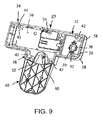
図1、8、9に示すように、収容室8は、更にT字型のスチール板14上に、T字型中空状周囲壁部26を備えており、T字型のスチール板14は、T字型中空状周囲壁部26の内にて固着し、しかもその下端部と同一の高さ状態を呈している。
As shown in FIGS. 1, 8, and 9, the
T字型中空状周囲壁部26は、T字型の板状主脚部14aの周囲のラインに沿って延設されている側方壁部28及び上側壁部30、端部に位置している水タンクに支持部32、中央水ポンプ及びヒータ支持部34及び末端における空気ポンプ支持部36を備えている。
The T-shaped hollow
T字型中空状周囲壁部26は、更にチューブの接続部分に対する支持部38を備えており、当該支持部38は、コップに対する平坦状の支持部40と共に、チューブの連結部に対する支持部38の前側から、T字型のスチール板14の中央脚部14bの残部に至るまでに、T字型のスチール板14の中央脚部14bに沿って部分的に延設されている。
The T-shaped hollow
複数の突起42は、上側壁部30から下側に降下しており、かつ突出開口部44を備えている。
The plurality of
前記開口部44を介して、ネジ46がT字型のスチール板14内にある開口部48中に挿入され、その結果、T字型中空状周囲壁部26は、T字型のスチール板14に固着されている。
Through the
T字型中空状周囲壁部26は、チューブと結合するために、上側壁部30を介して延設されている短いニップル、即ち乳首状の結合部50を備えている。
The T-shaped hollow
乳首状の結合部50の下端は、開口状態である一方、アーチ型の案内壁部52を設置することによって、全ての飲用液は、配管機能を有する乳首状の結合部を介して、コップに対する平坦状の支持部40の領域に注入されることになる。
While the lower end of the nipple-shaped
端部における水タンク支持部32には、上側壁部30の開口部54が備えられている。
The
環状案内壁部56は、前記開口部54を囲んだ状態にて上側壁部30の下側領域に接続しており、しかも突出開口部59を有している2個の突起部58が環状の案内壁部56の側部にて相互に相向かい合う状態にて備えられており、かつ上側壁部30の下側と接続している。
The
図10−12に示すように、水タンク接続部60は、環状案内壁部56の内側に固着している。
As shown in FIG. 10-12, the water
特に、水タンク接続部60は、底側壁部64によって閉鎖されている環状側方壁部62を備えているが、当該側方壁部62は、下側の中央にて円筒状凹部68を形成している中央の隆起状区画66を有している。
In particular, the water
その結果、中央の隆起状区画66を囲んだ状態にて環状凹部70が形成されている。
As a result, the
中央の隆起状区画66の頂部表面には、4個の等角状に配置された突起72が形成されている。
On the top surface of the central raised
2個の開口部74及び76が環状凹部70と連通状態にある環状側方壁部62内にて形成されており、しかも2個の外側に向かって伸長している乳首状の結合部78、80は、前記開口部74及び76と連通状態にある環状側方壁部62の外側表面と接続している。
Two
環状側方壁部62の外側表面からは、2個の相反する方向に向かい合っている突起82が延設されており、各突起82は開口部84を備えているが、当該開口部84を介してネジ(図示せず)が挿入され、しかも突出開口部59内に収容され、その結果、水タンク接続部60を環状案内壁部56内にて、上側壁部30の下側面に固着している。
From the outer surface of the annular
図13に示すように、弁駆動部86は、突起72の上側に当着されている。
As shown in FIG. 13, the
しかも、弁駆動部86は、下端部が円形状の底部によって閉鎖されている環状壁部88を備えており、当該円形の底側壁部90は、複数の小開口部92を有している。
Moreover, the
直立状態にある4個の弁駆動部突起94は、円形の底側壁部90の上側表面から上側に延設されており、かつ環状壁部88の上側表面よりも更に上側に延設されている。
The four valve drive unit protrusions 94 in an upright state extend upward from the upper surface of the circular
弁駆動部86が突起72上に当着されたとしても、弁駆動部86における円形の底側壁部90と底側壁部64及び水タンク接続部60の中央における隆起区画部分66との間に空隙が形成されており、その結果、水は小開口部92を介して当該空隙に流入し、しかも乳首状結合部78及び80を通過して流出することができる。
Even if the
図1、2、14及び15に示すように、水タンク4は、水タンク周壁部100を備えており、かつ調合に使用する水を供給するために設置されている。
As shown in FIGS. 1, 2, 14 and 15, the water tank 4 includes a water tank
水タンク周壁部100は、4個の側方壁部102、当該側方壁部102に対し密着状態にて載置している底側閉鎖部104、及び当該側方壁部102の上側端に位置している除去可能な被覆部106を備えている。
The water tank
底側閉鎖部104は、3個の側方壁部108を備えており、当該壁部108の上側端は、側方壁部102の下側端に対して当接し、かつ滑らかな連続状態を形成している。
The bottom-
上側壁部110は側方壁部108の上側端に接続し、かつ当該上側端の開口部及び上側壁部110上の周辺口部112を閉鎖している。
The
前記口部112は、上側壁部110の外側周囲からやや内側に配置されており、しかも側方壁部102の下側端と共に遮蔽状態を形成している。
The
中央開口部114は、上側壁部110内に形成される一方、環状弁支持突起116は、上側壁部110の下側面から下降し、かつ前記中央開口部114を囲んだ状態にある。
The
タンク弁120は、環状弁支持突起116内に摺動可能な状態にて結合している。
The
図16、17に示すように、タンク弁120は、環状底側リング122を備えており、当該リング122は、その内側にて半径方向に沿って等角度に延設されている壁部124を有している。
As shown in FIGS. 16 and 17, the
各壁部124は、中央にて直立している支柱126を内側端として延設され、かつ環状底側リング122の内側表面を外側端として接続されている。
Each
内側の中間環状ディスク128は、環状底側リング122と平行状態であって、しかも離れた状態にて配設されている。
The inner intermediate
4個の半径方向に沿って等角度方向に延設されている壁部130は、中間環状ディスク128の下側面と環状底側リング122の上側面との間にて接続されており、しかも半径方向に沿って等角度方向に延設されている壁部124と直交している。
The four
前記壁部130は、中央支柱126に接続され、かつ当該接続位置から半径方向に沿って外側に延設されている。
The
各半径方向に沿った延設壁部130は、下側区画132を有しており、当該下側区画132は、上側区画134よりも大きな外側半径を備えている。
The extending
このような配列の下に、4個の円周方向に沿って四分割された開口部136は、半径方向に延設されている壁部124に対し隣接し、かつ挟まれた状態にて配設されている。
Under such an arrangement, the four
タンク弁120は、前記の中間環状ディスク128に対し平行であり、かつ離れている上側環状ディスク138を備えており、かつこのような配列によって、当該ディスク138は、直径が縮小した状態にある頸部140に接続され、その結果、ディスク128と同138との間にて環状凹部142が形成されている。
The
図16、17、18、19に示すように、ガスケットリング、即ち漏洩防止用リング144が環状凹部142の領域内にて頸部140の周囲に載置されている。
As shown in FIGS. 16, 17, 18, and 19, a gasket ring, that is, a
ガスケットリング144は、中間環状ディスク128及び同138よりも大きな外側直径を有している。
The
このような設計において、タンク弁120が環状の弁支持突起116内に配置された場合には、ガスケットリング144は、底側閉鎖部104の上側壁部110の上側面に配置され、その結果、当該配置位置において、遮蔽状態を形成し、その結果、中央開口部114を介して水が流出することを防止することができる。
In such a design, when the
水に対する緊密な遮蔽状態を実現するために、タンク弁120とガスケットリング144を囲んだ状態にてコイル状バネ146が配置されている。
In order to realize a tight shielding state against water, a
コイル状バネ146の上側端は、底側閉鎖部104の上側壁部110の下側面と接触状態にあり、環状底側リング122の上側面と接触状態にある。
The upper end of the
前記コイル状バネ146の採用によって、ガスケットリング144を引っ張った状態とし、かつ底側閉鎖部104の上側壁部110の表面に対し、緊密な遮蔽を伴う接触状態を実現している。
By adopting the
水タンク4のその余の事項について説明するに、図20、21に示すように、水タンク接続部60における環状の側方壁部62の上側端にタンク注入リング148が当着されている。
The remaining matters of the water tank 4 will be described. As shown in FIGS. 20 and 21, a
タンク注入リング148は、上側環状壁部150を備えており、当該壁部150は、コイル状バネ146よりも大きな径を有しており、かつ傾斜状環状壁部154を境界として接続している。
The
外側の環状側方壁部156は、上側環状壁部150の周囲に接続すると共に、環状の側方壁部62の外側周囲にて結合するために、当該壁部62の外径と同程度の径を有している。
The outer annular
他方、内側の環状の側方壁部158は、上側環状壁部150の下側に結合すると共に、環状の側方壁部62とその内側周囲にて結合するために、当該壁部62の内径と同程度の径を有している。
On the other hand, the inner annular
換言するならば、環状凹部160が環状側方壁部156及び同158との間に形成されており、かつ環状側方壁部62の上端を収容している。
In other words, the
水タンク周壁部100及び底側閉鎖部104は、上側壁部30上に載置されている場合には、1個の単体として水によって充満されている。
When the water tank
更には、水タンク周壁部100及び底側閉鎖部104は、1個の単体として水によって充満されている場合には、上側壁部30から取り外しが行われた後、再び当該壁部30上に載置されることになる。
Furthermore, when the water tank
水タンク周壁部100及び底側閉鎖部104が上側壁部30上に載置された場合には、弁駆動部86の弁駆動用突起94がタンク弁120における環状底側リング122の下側面に衝突し、コイル状バネ146の力に逆らい、かつ当該バネ146を押した状態にてタンク弁120を上側に移動させる。
When the water tank
その結果、ガスケットリング144は、底側閉鎖部104の上側壁部110上側面との接触状態から上昇することになる。
As a result, the
そして、水タンク4内の水は、底側閉鎖部104内の中央開口部114、タンク弁120の周囲に位置している開口部54及び環状の導入壁部56を通過して流動し、かつタンク弁120の周囲を流動した後、タンク弁120内にて四分割されている開口部136を通過して流動することになる。
The water in the water tank 4 flows through the
更に、水は、弁駆動部86の小開口部92を通過した後、環状凹部70に流入し、かつ外側に延設されている乳首状結合部80を通過しながら流出している。
Furthermore, after passing through the
図22〜24に示すように、矩形テーブル頂部164及び当該テーブル頂部164の四隅における支持脚部166によって形成されている支持テーブル162は、T字型中空状周囲壁部26の上側壁部30であって、特に4個の円筒状に隆起した壁部27(図8)上に載置されている。
As shown in FIGS. 22 to 24, the support table 162 formed by the
当該壁部27は、中央の水ポンプ172及びヒータ34における上側壁部30上にあり、かつ突出開口部29を有している。
The
各支持脚部166は、中空状の脚が側方に開いた状態を呈しており、しかも下端において環状突起168を備え、当該突起168は円筒状に隆起した壁部27上に当着している。
Each
開口部170は、ネジ(図示せず)を支持脚部166における各環状突起168に挿入し、かつ中央の突出開口部29内に突入することを目的として設けられている。
The
上側壁部30は、中央部における水ポンプ及びヒータ支持部34によって形成されている矩形状の凹部領域31(図8)の領域内にて取り外しが行われている。
The upper
図23及び図24に示すように、水ポンプ172は、水を環状凹部70と外側に設置されている乳首状結合部80との間にて水を移送するために設けられている。
As shown in FIGS. 23 and 24, the
水ポンプ172は、注入パイプ174及び流出パイプ178を備えている。
The
前記注入パイプ174は、変形可能なチューブ176によって外側に延設されている乳首状結合部82と連通状態にて接続しており、前記流出パイプ178は、片側方向弁体180の入口181(図25)に配管179を介して結合している。
The
第1の腕木182は、注入パイプ174を囲んだ状態にて支持し、かつテーブル頂部164の下側に接続しており、第2の腕木184は、流出パイプ178を囲んだ状態にて支持し、同様にテーブル頂部164の下側に接続している。
The
図25に示すように、片側方向弁体180は、流出口186及び迂回乳首状結合部188を備えている。
As shown in FIG. 25, the one-
前記結合部188は、小孔(図示せず)を介して片側方向弁体180の下側領域と連通状態にある。
The
その結果、水ポンプ172によって片側方向弁体180を介して流動した水のうちの少量が、迂回乳首状結合部188及び水タンク連結部60の外側領域において、外側に延設されている乳首状結合部78との間に接続されている変形可能なチューブ190を介して環状凹部70側に戻ることができる。
As a result, a small amount of the water flowing through the one-
このような機構によって閉鎖した循環経路が形成され、その結果、ポンプは常時水を移送することができ、たとえ水タンク4が空の状態であっても、空気の移送を行う必要がない。 A closed circulation path is formed by such a mechanism, and as a result, the pump can always transfer water, and even if the water tank 4 is empty, there is no need to transfer air.
図23及び図24によって明瞭に示すように、水を加熱するヒータ192は、支持用テーブル162のテーブル頂部164上側面上に載置されており、かつ注入口194及び流出口198を備えている。
As clearly shown in FIGS. 23 and 24, the
前記注入口194は、片側方向弁体180の流出口186に変形可能なチューブ196を介して接続されており、当該流出口198は、変形可能なチューブ200に接続されている。
The inlet 194 is connected to the
前記ヒータ192は、加熱用コイル(図示せず)の作用によって、水を速やかに加熱し、しかも所望の温度を実現するような通常の熱交換装置を採用することが好ましい。
The
前記ヒータ192を通過する水の温度制御は、マイクロプロセッサー702(図89)の加熱コイルを通過する電流及び/又は加熱コイルの作動時間の制御という周知の方法によって実現している。
The temperature control of the water passing through the
図23及び図24に示すように、前記ヒータ192によって加熱された水は、チューブ200を通過してT字型接続部202における1個の注入口に流入する。
As shown in FIGS. 23 and 24, the water heated by the
T字型の接続部202の他の注入口は、変形可能なチューブ204を介して空気ポンプ206の排出口に接続されており、このような接続の目的については、後に詳細に説明するとおりである。
The other inlet of the T-shaped connecting
空気ポンプ206は、T字型中空状周囲壁部26内にある空気ポンプ支持部36の端部における上側壁部30上に載置されている。
The
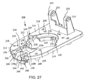
図26−33に即して説明するに、早い番号の図26−30に示すように、調合機構6は、下側の位置から隆起している状態にある調合支持機構207を備えている。
26-33, as shown in the earlier numbered FIG. 26-30, the
前記支持機構207は、調合下側支持部208を備え、当該支持部208は湾曲した前側端212を伴っている概略矩形状の上側壁部210及び当該前方端112の外側端部周辺を囲んだ状態にて下側に延設されている短い側方壁部214を有している。
The
上側壁部210及び側方壁部214は、矩形状の切除区画216によって後方にて切断された形態を呈している。
The upper
環状開口部218は、上側壁部210の略中央の位置に設けられている。
The
垂直下方延設案内壁部220は、環状開口部218の周辺にて、上側壁部210から延設されている。
The vertically downward extending
前記案内壁部220の下側端は内側に延設されている円形棚状部222の位置を下側端の限界としている。
The lower end of the
前記円形棚状部222は、垂直方向からやや傾斜した角度にて下側延設案内壁部224の位置を終端としている。
The
調合機構6の下方側においては、点対称の相向かい合う状態にある凹部区画226が中央開口部114の周辺にて形成されている。
On the lower side of the
各区画226は、突設した開口部30を有した状態にて下側凹状壁部228を備えている。
Each
対称状態にて相向かい合う状態にある導入開口部232は、前記凹部区画226に対し上下方向に沿って直交状態にある下方延設案内壁部224内に設置されている。
The
2個の相互に離れた状態にある耳部235は、上側壁部210から上側方向に直接延設されており、かつ上側壁部210の後方に位置している矩形状の切除区画216の反対側に配置されている。
The two
前記2個の耳部235は、前記切除区画216の前側の位置にて、略矩形状の切除区画236を有している。
The two
前記切除区画236は、前記耳部235の前側端部を連結する連結用板状壁部としての機能を発揮している。
The
耳部235は、上側端において軸方向整列開口部237を備えている。
The
施錠機構(後に説明する。)の機能を発揮するために、上側壁部210内には、大型の略矩形状の凹部区画234が備えられており、当該凹部区画234は、上側壁部210の前側に位置している略矩形状の切除区画236に接合している。
In order to exhibit the function of the locking mechanism (described later), a large, substantially
前記凹部区画234は、略矩形状の切除区画236の3個の端部周辺にて上側壁部210から下側に延設されている3個の側壁238a、238b及び238cを有する一方、前記切除区画236の前側端部及び側方壁部238の下端と接続している底側壁部240をも有している。
The recessed
2個の保持壁部242は、相互に反対側に位置している側方壁部238a及び238bの前側端からやや内側に延設されており、前記切除区画236の前側端を部分的に遮蔽する状態を呈している。
The two holding
底側壁部240は、中央にて細長状開口部244を備えており、しかも保持壁部242のやや後方に配置されている。
The
尚、前記底側壁部240は、底側壁部240から下方に延設されている壁部246を有しており、かつ細長状開口部244の外側周辺に沿い、かつ当該開口部244を囲んだ状態にて、案内ポケット248と接した状態にある。
The bottom
2個の筒状突起250は、底側壁部240の上側面から上方に延設されており、かつ突出上側開口部252を有した状態にて細長状開口部244の後方及び相向かい合う端部の位置に配置されている。
The two
2個のコーナー棚状部254は、底側壁部240の後方のコーナーから上側方向に延設され、しかも突出上側開口部256を有している。
The two corner shelf-
更には、上側壁部210内には、8個の開口部258が備えられる一方、筒状突起260が各開口部258と一体となって上側壁部210の下側面から延設されている。
Furthermore, eight
各筒状突起260は、前記各開口部258と連結状態にある階段状貫通開口部262を包摂している。
Each
図31−33に示すように、調合部支持機構207は、調合機構を調合作業中に閉鎖された位置に、調合機構6を保持するために施錠機構264を設けている。
As shown in FIGS. 31-33, the blending
上記構成において、施錠機構264は、押圧ボタン機構266を備えている。
In the above configuration, the
当該押圧ボタン機構266は、施錠板268及び中央の二分割された収納脚部274を備えている。
The
前記施錠板268は、各一方端を接合脚部272を介して相互に連結している上側及び下側の平行脚部270を有することによって、基本的に文字Eの形状を呈している。
The locking
前記収納脚部274は、上側の傾斜面276を自由端としている
相互に隣接状態にあるバネ受け脚部278は、平行脚部270を横断する状態にて外側に延設されている。
The
図31に示すように、平行脚部270は、調合下側支持部208のコーナー棚状部254と相互に結合し、かつ摺動している。
As shown in FIG. 31, the
コイル状バネ280は、コーナー棚状部254の前面とバネ受け脚部278との間に配置されており、施錠板268を、コーナー棚状部254から施錠位置に至る方向に沿って傾斜させている。
The
押圧ボタン282は、保持壁部284を有した状態にて略矩形状に形成されており、当該壁部284の後端側の両側から外側に延設されている。
The
押圧ボタン282は、矩形状の凹部区画234の前側開口端部に配置されており、当該区画234は、調合下側支持部208の保持壁部242とバネ受け脚部278の反対側面との間にて挟まれた状態にある保持壁部284を有している。
The
施錠による配置の場合には、コイル状バネ280は、バネ受け脚部278に対し、保持壁部284が調合下側支持部208の保持壁部242と接触し、かつ傾斜するように作用している。
In the case of the arrangement by locking, the
このような配置状態においては、押圧ボタン282の前側部分は、図1において明瞭に示すように、調合下側支持部208から外側に延設された状態を呈している。
In such an arrangement state, the front side portion of the
これらの構成要素が離脱することを防止するために、収納被覆板286(図34)が施錠板268の頂部に当着されており、かつ4個の開口部288を備えている。
In order to prevent these components from detaching, a storage cover plate 286 (FIG. 34) is attached to the top of the
前記開口部288は、ネジ(図示せず)を挿入し、かつ施錠板268を保持するために、調合下側支持部208の突出開口部252及び256と整列状態を呈している。
The
前記ネジの挿入によって施錠板268は保持され、かつスライドによる移動が制限されることになる。
The locking
図31、35、36及び84に示すように、施錠機構264は、鉤支持部290を備えており、当該支持部290は、後述するような上側の旋回機構に固着されている。
As shown in FIGS. 31, 35, 36 and 84, the
鉤支持部290は、上側連結板292及び矩形状の施錠開口部298を備えている。
The eaves support 290 includes an upper connecting
前記上側連結板292は、2個の開口部294を有しており、当該2個の開口部294は、上側の旋回機構に結合するために鉤支持部290の端部にて相向かい合う状態にて設けられている。
The upper connecting
前記矩形状の施錠開口部298は、鉤支持部290の下端側に配置されている。
The
前記上側連結板292は、当該連結板292の下側面から下側に延設されている施錠板296を有している。
The upper connecting
調合作業中の調合機構6が閉鎖状態にある場合には、施錠板296は、調合下側支持部208の案内ポケット248内にスライド可能な状態にて配置されている。
When the
後述する上側の旋回機構が調合作業を開始するために閉鎖状態となった場合には、施錠板296の下端は、施錠板268の上側傾斜面276に衝突し、当該施錠板268に対しコイル状バネ280の弾性力に逆らって摺動している。
When the upper turning mechanism, which will be described later, is closed to start the blending operation, the lower end of the
施錠板296が案内ポケット248内にて摺動している場合には、中央の二分割された施錠脚部274は、施錠開口部298と整列した状態と化し、コイル状バネ280は、施錠板268に対し前方に摺動するような弾性力を加えており、その結果、中央の二分割された施錠脚部274は、施錠開口部298内に配置され、その結果、鉤支持部290の離脱が防止され、かつ調合機構6が施錠位置に配置されることになる。
When the
調合作業が完了した段階では、押圧ボタン282は後方に押され、その結果、施錠板268は、コイル状バネ280の弾性力に逆らって摺動している。
When the blending operation is completed, the
このような作動の結果、中央の二分割された施錠脚部274は、施錠開口部298から離脱し、鉤支持部290及び上側の旋回機構が従前の位置から離脱し、更には、調合機構6は、施錠位置から離脱することになる。
As a result of such an operation, the centrally divided locking
図23及び90に示すように、調合支持機構207は、調合下側支持部208の頂部に保持されている下側被覆部300を備えている。
As shown in FIGS. 23 and 90, the blending
図37及び38に示すように、下側被覆部300は、調合下側支持部208の上側壁部210と概略同一形状を呈しており、かつ略矩形状の上側壁部302及び狭幅の側方壁部306を備えている。
As shown in FIGS. 37 and 38, the
前記上側壁部302は、湾曲前方端304を有しており、側方壁部306は、下側に延設され、かつ外側周囲の端縁を形成している。
The upper
上側壁部302及び側方壁部306は、矩形状切除区画308の後方にて切除されるような配置状態を呈しており、当該区画308は、調合下側支持部208の矩形状の切除区画216よりも広幅に設計されており、その結果、耳部235を挟持することができる。
The upper
円形開口部310は、上側壁部302の略中央位置に設けられている。
The
4個の突起312は、上側壁部210の下側面から下側に延設され、円形開口部310を囲んだ状態を呈しており、しかも調合下側支持部208の上側壁部210内に備えられている4個の開口部258と整列状態を呈している。
The four
ネジ(図示せず)は、突起312における開口部及び開口部258を貫通し、しかも収容室8の前側の上側面に載置されている突起772(図94)における突出開口部770内に挿入されている。
A screw (not shown) passes through the opening and the
その結果、下側被覆部300及び調合下側支持部208は、収容室8内に固着されている。
As a result, the
更には、下側被覆部300は、細長状開口部314を備えており、当該開口部314は、調合下側支持部208の細長状開口部244と整列状態にあり、その結果、調合機構6が開口状態及び閉鎖状態の何れの段階であっても、鉤支持部290の施錠板296の摺動による移動を可能としている。
Furthermore, the
図39−42に即して説明するに、調合支持機構207は、調合上側支持部316を備えており、当該支持部316は、湾曲前方端部320を伴っている下側壁部318及びその外周端の周囲にて上側に狭幅状態にて延設されている側方壁部322を有している。
39-42, the blending
湾曲把持ハンドル324は、下側壁部318の湾曲した前側端に形成されており、その結果、ユーザーは、当該ハンドルを把持することによって、調合支持機構207を開口し、かつ閉鎖することができる。
The curved grip handle 324 is formed at the curved front end of the
円形開口部326は、下側壁部318の略中央位置に備えられている。
The
垂直上側方向延設壁部328は、円形開口部326の外側周囲にて下側壁部318の上側に設けられており、内側に延設された上側環状棚状部330を上側端としており、当該棚状部330は、円形開口部332を形成している。
The vertically upward extending
下側壁部318及び上側方向延設壁部328は、相互に直交状態にて交差している。
The
しかも、対称状態にある相向かい合う位置において、2個の直交開口区画333が形成されると共に、その後側の領域にて、後方開口区画334が形成され、その結果、2個の後側島状区画336及びアーチ型の前側区画338が実現するに至っている。
In addition, two
各後側島状区画336は、環状棚状部330を介して延設されている凹状区画340を備えると共に、小開口部342を有している。
Each
同様に、凹状区画344が前側区画338の下側壁部318の後方の中央部に備えられており、かつ環状棚状部330を介して延設されている小開口部346を有している。
Similarly, a
調合上側支持部316は、下側壁部318に対し、直交し、かつ囲んだ状態にて、当該壁部318から延設されている4個の突起348、上側方向延設壁部328を備えると共に、下側壁部318を介して延設されている階段状の開口部350を有している。
The blending
細長状開口部352は、下側壁部318のうち、前側区画338に設けられており、かつ細長状開口部244及び同314と整列状態にある。
The
2個の突起351は、細長状開口部352と隣接し、かつ相互に向かい合う状態にて備えられており、何れも、突出開口部353を有している。
The two
このような配置状態の下に、鉤支持部290の上側連結板292は、突起351上に配置され、かつ細長状開口部352を介して延設されている施錠板296を備えている。
Under such an arrangement state, the upper connecting
ネジ(図示せず)は、開口部294を貫通し、かつ突出開口部353内に突入することによって、鉤支持部290を保持している。
A screw (not shown) passes through the
2個の相互に離れた状態にある耳部354は、上側環状棚状部330の後方の相互に向かい合う側方の位置から上側に延設されている。
The two
耳部354の間における内側のスペースは、耳部235を挿入するために当該耳部354の外側のスペースと同程度に設定されている。
The inner space between the
耳部354は、上側端にて同軸方向に設定されている開口部356を備えており、当該開口部356は、耳部235において同軸方向に設定されている開口部237と整列状態に配置されている。
The
小耳部358は、各耳部354から後方側に延設されており、しかも直交開口部360を有している。
The
このような配置構成の下に、拡大した機構図43に示すように、回転軸362は、開口部237及び356を貫通した状態にて延設されており、かつ調合下側支持部208に対する調合上側支持部316を回転可能な状態にて載置している。
Under such an arrangement, as shown in FIG. 43 in which the mechanism is enlarged, the
しかも、耳部235は、回転軸362上に回転可能な状態にて載置されている。
Moreover, the
これに対し、耳部354は、回転軸362に固定されている。
On the other hand, the
その結果、調合上側支持部316は、調合下側支持部208に相向かい合う段階、又は離脱する段階の何れにおいても、回転軸362と共に回転することができる。
As a result, the blending
調合下側支持部208が固定状態にあることから、調合上側支持部316は調合下側支持部208に対して旋回することに基づき、開口状態及び閉鎖状態の双方を実現することができる。
Since the lower
図43に示すように、第1交差腕364は、軸ピン366によって軸支された状態にて各小耳部358の一方端に接続されている。
As shown in FIG. 43, the
第2交差腕368は、軸ピン369によって軸支された状態にて、第1交差腕364の反対側の他方端部に接続されている一方端を有しており、しかも第3交差腕370は、軸ピン371によって軸支された状態にて、第2交差腕368の反対側に位置している他方端に接続している。
The
第3交差腕370の他方端部は、フリーの状態にある。
The other end of the third
コイル状引張バネ372は、第3交差腕370の側部に載置されている突起部374と、第1交差腕364における開口部376との間に接続されている。
The coiled
このような交差した状態による機構によって、調合上側支持部316においては、調合下側支持部208から上側方向に旋回しかつ離脱することによって、開口状態を維持する一方、調合下側支持部208に対して下側方向に旋回しかつ一体状態となることによって、閉鎖状態を維持している。
By such a mechanism based on the crossed state, the upper
図1、26、40、44、及び45に示すように、調合支持機構207は、前側被覆部378を備えており、当該被覆部378は、調合上側支持部316の頂部に固着され、一体となって移動している。
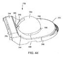
As shown in FIGS. 1, 26, 40, 44, and 45, the blending
前側被覆部378は、湾曲前側端382及びカーブを描いた状態にて隆起している後側部分を有している略矩形状の上側壁部380を備えている。
The
中央開口部386は、上側壁部380中に設けられており、かつ調合上側支持部316の上側環状棚状部330内に位置している開口部332と整列状態を呈している。
The
透明な半球状屋根状部388は、中央開口部386における上側壁部380に固着されており、しかも突出状態を呈している下側環状部分390を備えている。
The transparent hemispherical roof-shaped
前記下側環状部分390は、上側壁部380の下側にて延設されている。
The lower
前側被覆部378が調合上側支持部316と一体になって結合している段階では、前記突出状態を呈している下側環状部分390は、上側環状棚状部330内に位置している開口部332の内側に挿入され、かつ当該開口部332の下側に伸長している。
At the stage where the
矩形状小開口部392は、屋根状部388の上端かつ真後に位置し、しかも上側方向に湾曲した後側矩形状壁部384の中央位置に備えられており、T字型開口部393は、屋根状部388の後方にて前記小開口部392と相互に開口状態を形成しながら連結している。
The rectangular
狭幅矩形状壁部394は、上側方向に湾曲した後側矩形状壁部384の後端から更に後方に延設されており、しかも上側壁部380と並行状態を呈している。
The narrow
耳状壁部396は、狭幅矩形状壁部394から更に後方に延設されている。
The ear-shaped
側方壁部398は、上側壁部380の外側周囲から下方に延設されており、しかも上側に湾曲した後側矩形状壁部384、狭幅矩形状壁部394及び耳状壁部396を囲んでいる。
The
側方壁部398は、相互に反対方向に位置している矩形状切除区画400を備えており、当該区画400は、調合上側支持部316の直交開口区画333と整列状態を呈している。
The
4個の階段状突起402は、上側壁部380の下側面から延設されており、突出開口部404を備えている。
The four stepped
階段状突起402は、調合上側支持部316の開口部350内に配置されており、ネジ(図示せず)は、前側被覆部378を調合上側支持部316に固着している。
The stepped
図46−51に即して説明するに、調合支持機構207は、部分的球形状である基礎壁部408を有しており、当該壁部408は、調合下側支持部208における環状開口部218を介して延設され、かつ下側延設案内壁部224に沿って案内されている。
46-51, the blending
環状棚状部410は、部分的球形状である基礎壁部408の上端から半径方向外側に延設されており、調合下側支持部208の内側に延設されている円形棚状部222上に当着している。
The
環状案内壁部412は、環状棚状部410の外側端から上側に延設されていると共に、調合下側支持部208において垂直下方延設案内壁部220に面した状態にて当着している。
The
隆起した状態にある環状溝部413は、環状案内壁部412の上側面に形成されている。
The
お茶調合支持部406は、環状案内壁部412の外側面にて相向かい合う対称の位置に結合耳部414が設けられており、各結合耳部414は、開口部416を有している。
The tea
前記開口部416においては、ネジ(図示せず)が挿入され、かつ各突出開口部230内を貫通することによって、お茶調合支持部406を調合下側支持部208に結合している。
In the
2個の対称に相向かい合う案内壁部418は、部分的球形状である基礎壁部408の外側面から延設されており、調合下側支持部208の導入開口部232内に当着している。
Two symmetrically facing
案内壁部418は、部分的球形状である基礎壁部408の内側面にてL字型凹部419を形成している。
The
このような配置構成によって、下側被覆部300は、調合下側支持部208及びお茶調合支持部406の頂部上に当着している。
With such an arrangement, the
お茶調合支持部406は、部分的球形状である基礎壁部408内にて2個の水注入開口部420を備えており、当該開口部420を介して、水は後述の調合室内に噴入される。
The tea
2個のチューブ止着接続部422は、部分的球形状である基礎壁部408の下側の外側面に形成されており、前記開口部420と連通状態を呈している。
The two tube
このようにして、加熱水は図24に示すように、水を加熱するヒータ192からチューブ200を介してT字型連結部202の一方側の注入部に流入し、更には、T字型連結部202からチューブ424を通過する。
In this way, as shown in FIG. 24, the heated water flows from the
図52に示すように、チューブ424は、T字型注入連結部材428(図53)の注入口426に接続されており、当該連結部材428は、第1流出突起430と第2流出口432を備えている。
As shown in FIG. 52, the
T字型注入連結部材428は、開口部436に対し横断状に結合し、かつ開口部436を有し、かつ当該連結部材428と直交状態を呈している結合耳部434を備えており、当該開口部436を介してネジ438は突起442の突出開口部440内に挿入される。
The T-shaped
前記突起442は、各チューブ止着接続部422の反対側にて部分的球形状である基礎壁部408の外側面から下側に延設されている。
The
このような結合による配置関係において、第1流出突起430は、チューブ止着接続部422の両側に緊密な状態にて挿入され、各水注入開口部420に対し、加熱水の供給を可能としている。
In such an arrangement relationship due to the coupling, the
変形自在のチューブ444(図52)は、T字型注入連結部材428の第2流出口432から延設され、かつ調合機構6において反対側に配置されている注入接合部448(図54)の注入口446に接続されている。
The deformable tube 444 (FIG. 52) extends from the
注入接合部448は、他のチューブ止着接続部422内に緊密に挟着されている排出突起450を有しており、その結果、各水注入開口部420に対し加熱水が供給されている。
The
注入接合部448は、開口部454を有している直立した結合耳部452を備えており、当該開口部454を介して、ネジ456が突起442の突出開口部440内に挿入されかつ収容されている。
The injection joint 448 includes an
そして、前記突起442は、部分的球形状である基礎壁部408の外側面から下側に延設されており、当該基礎壁部408はチューブの他方端との止着接続部422の相互に相向かい合う側部に配置されている。
The
このような結合を伴う配置に基づき、排出突起450は、チューブの他方端との止着接続部422内に緊密に挟着され、その結果、各水注入開口部420に対し加熱水を供給することができる。
Based on the arrangement with such coupling, the
改めて図46−51を参照した場合、お茶調合支持部406が部分的球形状である基礎壁部408の下側中央部に円形開口部458を更に備えていることを確認することができる。
46-51, it can be confirmed that the
環状壁部460は、円形開口部458から直交した状態にて延設され、かつ内側延設棚状部462の位置を下端としている。
The
そして、当該棚状部462は、下側に延設されている他の環状壁部464の位置を他方端として結合している。
And the said shelf-
環状壁部464の下側端は、底側壁部466によって閉鎖されている。
The lower end of the
対称状態にて相向かい合っている2個の薄型凹部区画468は、環状壁部460及び部分的球形状である基礎壁部408の底部の位置に備えられており、かつ当該壁部460と面した状態を呈している。
Two thin recessed
アーチ型凹部470は環状壁部464内に形成されており、かつ薄型凹部区画468と整列状態を呈しており、かつ小開口部472が、底側壁部466のうち、前記凹部470のやや外側位置に形成されている。
The
調合飲用液が小開口部472を介して流出することについては、後述する通りである。
The fact that the mixed drinking liquid flows out through the
チューブ止着接続部474は、底側壁部466の外側面の下側にて形成されており、しかも小開口部472と連通状態を呈している。
The tube
突起476は、チューブ止着接続部474に対し相向かい合う両側の位置にて、部分的球形状である基礎壁部408の外側表面から延設されており、何れも突出開口部478を備えている。
The
図55−57に示すように、調合支持機構207は、お茶の葉支持リング480を備えている。
As shown in FIGS. 55-57, the blending
当該支持リング480は、お茶調合支持部406の頂部に当着しており、かつ環状案内壁部484を有している環状頂部側方壁部482を備えている。
The
当該壁部484は、当該環状頂部側方壁部482から直交した状態にて延設されており、かつ環状肩部486が形成されている内側周囲の領域に配置されている。
The
このような構成によって、環状案内壁部484は、お茶調合支持部406における環状案内壁部412内に挟着されており、かつその下端は、環状棚状部410上に当接している。
With such a configuration, the annular
しかも、環状肩部486は、お茶調合支持部406における環状溝部413上に当着されている。
Moreover, the
お茶の葉支持リング480は、更に環状頂部側方壁部482の内側周辺から所定の角度にて内側に延設されている環状案内壁部488を備えている。
The tea
調合飲用液を、お茶調合支持部406の小開口部472を介して、適切に吸引しかつ濾過することを目的として、図58−63に示すように、網状お茶流出機構490が、環状壁部460内に密着した状態にて挟着されており、しかも当該お茶調合支持部406において、内側延設棚状部462に当着している。
For the purpose of appropriately sucking and filtering the blended drinking liquid through the
しかも、網状お茶流出機構490は、流量制御円盤492を備えており、当該円盤492は、環状溝496を有している環状外側壁部494を備えている。
In addition, the net-like
流量制御円盤492の底部は、環状底側壁部498によって閉鎖されており、当該壁部498は中央の円形凹領域500を有しており、当該領域500は、小開口部502を備えている。
The bottom of the
環状底側壁部498の外側周囲には、隆起した環状棚状部504が備えられている。
A raised
隆起した環状棚状部504の高さは、環状外側壁部494の高さよりも小さく、その結果、隆起した環状棚状部504の上側表面は環状肩部506と接した状態にある。
The height of the raised
例えば、8個という複数個の半径方向に延設されている横枠508は、環状壁部460の内側面から更に内側に延設されており、その内側端部は、小開口部502を囲んだ状態を呈している。
For example, a plurality of eight
ゴム製リング510は、環状溝496の内側にて流量制御円盤492を囲んだ状態にて延設されている。
The
小網状開口部514を有している網状遮蔽部512は、環状肩部506及び横枠508上に配置されている。
A
そして、閉鎖板516は、網状遮蔽部512に当着した状態にて、流量制御円盤492の環状外側壁部494内に着脱自在にて挿入されており、その結果、閉鎖板516の上側面は、環状外側壁部494の上側面と同一平面を形成している。
The
閉鎖板516は、環状リング板518及び当該4個の等角度に配列されている横枠520を備えており、当該横枠520は、環状リング板518から内側に延設され、中央にて相互に結合した結果、四等分された開口部522を形成している。
The
かくして、網状お茶流出機構490が環状壁部460内に遮蔽状態にて挿入され、しかもお茶調合支持部406における内側延設棚状部462に当着している段階では、中央の円形凹領域500は、底側壁部466よりもやや上側に配置されている。
Thus, at the stage where the net-like
その結果、調合された飲用液は、四等分された開口部522、網状遮蔽部512、小開口部502を通過し、小開口部472から流出している。
As a result, the prepared drinking liquid passes through the equally divided
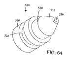
銅製の注入接合部524(図64及び65)は、お茶調合支持部406の各水注入開口部420に挿入されている。
Copper injection joints 524 (FIGS. 64 and 65) are inserted into each water injection opening 420 of the
各注入接合部524は、遮蔽リング(図示せず)が捲着する外側の円周状溝部を有する下側筒状体526を備えている。
Each injection joint 524 includes a lower
縮小径状の上側筒状体530は、下側筒状体526の上側に形成されており、円錐台区画部532によって上側端を形成している。
The reduced-diameter upper
第1の径を有する貫通穴534は、下側筒状体526を貫通した状態にて第2の径を有している貫通穴536と連通状態を形成しており、かつ上側筒状体530及び円錐台区画部532を貫通している。
The through
このような構成の結果、貫通穴536及び水注入開口部420を介して順次径が小さくなる領域から流出する加熱水を加速するという噴流状態を実現することができる。
As a result of such a configuration, it is possible to realize a jet state in which heated water flowing out from a region where the diameter is gradually reduced through the through
図66−75に即して説明するに、調合機構6は、移動可能であって調合作業中に調合原料を収容している調合室機構538を更に備えており、当該機構538は、お茶調合支持部406内に移動し、かつ挿入されている。
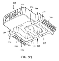
66-75, the
移動可能な調合室機構538は、底側コップ状区画540と頂部屋根状被覆区画542とを備えており、当該被覆区画542は、ヒンジ部544によって底側コップ状区画540に蝶番状に結合しており、その結果、隆起した開放形態と下降した閉鎖形態との双方を旋回によって実現することができる。
The movable
底側コップ状区画540は、一部切断タイプの球型コップ状体546を備えており、当該コップ状体546は、外側環状棚状部548と内側環状棚状部550を備えている。
The bottom cup-shaped
外側環状棚状部548は、前記底コップ状区画540の外側壁部からその上側端に対しやや下側領域にて、外側に延設されており、内側環状棚状部550は、前記底側コップ状区画540の内側壁部から、その上側端のやや下側領域にて内側に延設されている。
The outer
ヒンジ部544の関節部552は、コップ状体546の外側面から外側環状棚状部548の開口部分に接続し、かつ当該開口部分を通過する状態にて外側に延設されており、しかも貫通開口部554を備えている。
The
前記コップ状体546の底部は、大中央排出開口部556を備えており、当該開口部556は、コップ状体546の環状底側壁部558によって部分的に閉鎖された状態となっている。
The bottom of the cup-shaped
環状底側壁部558は、閉鎖板560によって部分的に閉鎖されている。
The annular bottom
前記閉鎖板560は、環状リング板562及び横枠板564によって形成されている。
The
前記横枠板564は、環状リング板562から内側に延設され、しかも中央部において相互に結合し、かつ4個の等角度の配列によって、四等分された開口部566を形成している。
The
閉鎖板560の厚みは、底側壁部558の厚みよりも小さい一方、閉鎖板560の底側面は、底側壁部558の外側面と同一平面を形成している。
The thickness of the
前記厚みの相違によって、環状リング板562の上面側に環状肩部567が形成されている。
Due to the difference in thickness, an
2個の点対称の状態にて相向かい合っているL字型案内壁部568は、一部切断タイプの球型コップ状体546の外側面から延設されており、調合作業の段階では、お茶調合支持部406の案内壁部418によって形成されているL字型凹部419内にて着脱自在の状態にて載置されている。
The two L-shaped
更には、2個の点対称状態にて相向かい合った状態にて設置されている噴射開口部570がL字型案内壁部568に対し、直角方向の位置にて一部切断タイプの球型コップ状体546内に形成されている。
Further, the injection opening 570 installed in a state of being opposed to each other in two point symmetry states is a partially cut type spherical cup at a position perpendicular to the L-shaped
噴射開口部570は、前記コップ状体546の中央ラインから離れた状態にて配置されている。
The
L字型案内壁部568がL字型凹部419内に嵌入された段階では、噴射開口部570の下端は、各注入接合部524の貫通穴536との間にて外側を遮蔽状態とし、かつ相互に連通状態としたうえで配置されている。
At the stage where the L-shaped
その結果、加熱水は、噴射開口部570を介して移動可能な調合室機構538内に噴出されている。
As a result, the heated water is jetted into the
調合原料と一体となっている加熱水において、渦流状態、より好ましくは、激しい乱流状態を実現するために、噴射開口部570は、点571(図75)の位置、即ち頂部屋根状被覆区画542の頂部中央よりやや下側の位置に向かって、多少内側角度方向に設定されている。 In order to achieve a swirling state, more preferably a severe turbulent state, in the heating water integrated with the blended raw material, the injection opening 570 is located at the point 571 (FIG. 75), ie the top roof-like covering section. The angle is set somewhat inwardly toward the position slightly below the center of the top of 542.
その結果、移動可能な調合室機構538内に流入した加熱水は、激しい乱流状態を形成し、当該加熱水と調合原料とが強制的に混合し合うことになる。
As a result, the heated water flowing into the movable
渦流の場合には、水と調合原料とが同一速度及び同一方向にて流動するため、双方はある程度の相互に混合し合う状態に至るが、十分な混合状態に至る訳ではない。 In the case of the vortex, water and the mixed raw material flow at the same speed and in the same direction, so that both of them are mixed to a certain extent, but they do not reach a sufficient mixed state.
これに対し、乱流、特に激しい乱流の場合には、加熱水は流動方向の変化を伴いながら調合原料内に流入し、加熱水と調合原料との間には多量の混合状態が発生することになる。 On the other hand, in the case of turbulent flow, particularly intense turbulent flow, the heated water flows into the mixed raw material with a change in the flow direction, and a large amount of mixed state occurs between the heated water and the mixed raw material. It will be.
底型コップ状区画540は、細長ハンドル572を更に備えており、当該ハンドル572は、一部切断タイプの球型コップ状体546の上端から延設されており、ヒンジ部544の関節部552と点対称にて相向かい合う位置にある。
The bottom cup-shaped
このような前記ハンドル572によって、使用者は、移動可能な調合室機構538を調合作業の後にお茶調合支持部406から除去することができ、しかも調合作業を開始する場合には、移動可能な調合室機構538をお茶調合支持部406に配置することができる。
Such a
前記ハンドル572は、調合上側支持部316における直交開口区画333又は前側被覆部378における矩形状切除区画400の何れか一方から突出した状態にて伸長している。
The
円形の網状遮蔽部、即ち小網状開口部514を有している円形網状遮蔽部512は、環状リング板562上に当接し、閉鎖機能を有する板、即ち閉鎖板516は、網状遮蔽部上に配置され、環状底側壁部558内に着脱自在にて結合しており、その結果、閉鎖板516の上側面は、環状底側壁部558の上側面と同一平面を形成している。
A
従って、前記閉鎖板516においては、環状リング板及び当該リング板から内側に延設されている等角度に配列された横枠520は、中央にて結合し、かつ四等分された開口部522を形成している。
Accordingly, in the
頂部屋根状被覆区画542は、下側筒状区画576を有している透明屋根状部574を備えており、当該区画576は、その上側部分がガラス又はプラスチック製の透明な一部球型区画578によって閉鎖されている。
The top roof-shaped
開口部580は、一部球型区画578の上側領域の中央位置に形成されている。
The
環状壁部582は、一部球型区画578における開口部580の上側端から内側に延設されており、更なる小型開口部584と接しており、かつ当該開口部584は、上側に傾斜環状壁部586を有している。
The
環状スカート部588は、一部球型区画578の上側端部から開口部580を囲んだ状態にて下側に延設されており、しかも開口部580よりも更なる大型開口部589と接した状態にあり、更には、環状肩部590との間にても接した状態にある。
The
環状棚状部592は、筒状区画576の下側端から短い距離を以って、外側に延設されており、しかも環状溝部594は、筒状区画576の一部領域のうち当該環状棚状部592の下方の位置に形成されている。
The
短ハンドル596は、環状棚状部592から半径方向外側に延設されている。
The
2個の相互に離れた状態にある関節部598は、環状棚状部592から外側に延設されており、前記ハンドル596と点対称状態にて向かい合っており、しかも整列開口部600を備えている。
The two
このような配列構成の下に、ピン602が整列状態にある関節部552の開口部554及び整列状態にある関節部598の開口部600内に挿入され、その結果、頂部屋根状被覆区画542は底側コップ状区画540と蝶番状態にて結合することができる。
Under such an arrangement, the
しかも、Oリング603(図75)は、溝部594内に挿入されている。
Moreover, the O-ring 603 (FIG. 75) is inserted into the
かくして、頂部屋根状被覆区画542が閉鎖状態にある場合には、環状棚状部592の下側面は、底側コップ状区画540のうち、一部切断タイプの球型コップ状体546の上側面に当着しており、しかも環状棚状部592の下側に位置している筒状区画576の一部領域は、溝部594内のOリングに沿って、一部切断タイプの球型コップ状体546内に嵌合しており、しかも前記コップ状体546の内側面に対し、Oリング603の介在によって遮蔽状態を形成している。
Thus, when the top roof-shaped
従って、本発明においては、移動可能な調合室機構538は、水を調合物内に効率的に進入させるような配置が可能であり、特に当該物がお茶の葉である場合には、当該お茶の葉から風味を効率的に抽出することができる。
Accordingly, in the present invention, the movable
このような作用効果は、移動可能な調合室機構538内に加熱水を補充し始める最初の段階に空気が当該機構538から散逸する段階だけでなく、その後加熱水が当該機構538内に補充され、かつ空気が当該機構538から散逸する際に、当該機構538を加圧することによって実現されている。
Such an effect is not only in the stage where air is dissipated from the
このような作用効果によって、加熱水が補充されている段階では、移動可能な調合室機構538の上側端において、外気又は蒸気の進入を封ずることができる。
By such an effect, when the heated water is replenished , the entrance of outside air or steam can be blocked at the upper end of the movable
噴射開口部570における加熱水の噴出及び移動可能な調合室機構538における加圧の結果、当該機構538内に進入した加熱水の攪拌状態及び乱流状態を実現し、更には、当該加熱水と調合物質との良好な混合状態を実現し、その結果、当該調合物からの風味を効率的に抽出することができる。
As a result of the ejection of the heated water at the injection opening 570 and the pressurization at the movable
このような作用効果を達成するため、タンク被覆リング604(図75−78)は、頂部屋根状被覆区画542の開口部580に圧着されている。
To achieve this effect, the tank covering ring 604 (FIGS. 75-78) is crimped to the
タンク被覆リング604は、外側環状壁部606を備えており、当該壁部606は、その外側面に環状凸部608を備えている。
The
前記凸部608の外側面は、環状スカート部588の内側面を圧着しており、その結果、開口部580との間にて遮蔽状態を形成している。
The outer side surface of the
このような結合構成において、外側環状壁部606の下側端は、環状肩部590と同一平面を形成している。
In such a coupling configuration, the lower end of the outer
内向環状頂部壁部610は、外側環状壁部606の上側端と結合しており、しかも環状壁部582の下側面と隣接している。
The inward annular
その結果、タンク被覆リング604が開口部580と結合した場合には、注入開口部612は、頂部屋根状被覆区画542における更なる小型開口部584の下端部と同程度の径を形成している。
As a result, when the
内側にて環状を呈している内側環状案内壁部614は、弾性変形が可能であって、頂部屋根状被覆区画542の内側端から内側に傾斜した所定の角度を以って下側に伸長し、しかもその下側の環状端において、更なる小型開口部616を形成している。
The inner annular
図75、76及び79-83に示すように、タンク被覆遮蔽部618は、タンク被覆リング604における外側環状壁部606内にて圧着されている。
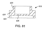
As shown in FIGS. 75, 76, and 79-83, the
しかも、タンク被覆遮蔽部618は、外側環状壁部606の内側径と同程度の外側径を有している上側環状壁部620を備えており、前記圧着を実現している。
In addition, the tank
更には、タンク被覆遮蔽部618は、前記上側環状壁部620よりも大きな径を有している下側環状壁部622を備えている。
Further, the tank
中央環状接合壁部624は、上側環状壁部620と下側環状壁部622とを接続しており、かつ下側環状壁部622の外径と等しい外径を有する一方、上側環状壁部620の内径と等しい内径を有している。
The central annular
四等角度配分横枠626は、中央環状接合壁部624の下端表面から内側に延設されており、しかも中央位置において相互に接続し合うことによって、四等分開口部628を形成している。
The quadrangular distribution
図75、76、82及び83に示すように、環状結合板630が頂部屋根状被覆区画542における環状スカート部588の下端を堅固に捲着した状態にて備えられており、当該環状結合板630は、環状スカート部588を押圧することによって、タンク被覆リング604及びタンク被覆遮蔽部618を保持している。
As shown in FIGS. 75, 76, 82, and 83, the
環状結合板630は、上側傾斜面632を備えており、当該傾斜面632は、頂部屋根状被覆区画542に接続し、かつ環状結合板630における下側湾曲面634に隣接している。
The
図75、76に示すように、閉鎖板516と同一構造である閉鎖板636は、下側環状壁部622内に着脱自在にて結合しており、その上側面は、環状接合壁部624の下側中央面と隣接状態を呈している。
75 and 76, the
網状遮蔽部(図示せず)を閉鎖板636と環状接合壁部624との間に挟着することもできる。
A mesh shield (not shown) may be sandwiched between the closing
図75、76及び84に示すように、流出頭部638は頂部屋根状被覆区画542の開口部584内に挟着されている。
As shown in FIGS. 75, 76, and 84, the
空気を除去するために、前側被覆部378が閉鎖された場合には、状況如何によっては、加熱水が補充されている段階にある移動可能な調合室機構538から少量の余分な飲用液が必要に応じて流出頭部638を介して流出されている。
If the
前記各図面に示すように、流出頭部638は、筒状上側区画640、円錐台型下側区画642及び側方開口部648を備えている。
As shown in the drawings, the
前記下側区画642は、その下端部において開口状態を呈し得る開口部646を形成する中央軸状空洞部644を備えており、前記側方開口部648は、筒状上側区画640の外側面を形成し、かつ前記軸状空洞部644の上側端と連通状態を呈している。
The
その結果、加熱水が補充されている段階では、空気は調合室区画538の上側端への強制的な流動を余儀なくされ、更には開口部646、中央軸状空洞部644及び側方開口部648を介して流出している。
As a result, air is forced to flow to the upper end of the
余分な液体が存在する場合には、同じような流出状態が実現することになる。 If there is excess liquid, a similar outflow condition will be realized.
変形しないチューブ650の一方端は、側方開口部648に接続され、当該チューブ650の他方端は、回転軸362に軸支されている送風回転機構652に接続されている。
One end of the
その結果、調合上側支持部316が前側被覆部378と共に、上側に押し上げられた段階では、調合上側支持部316の旋回を原因として、回転軸362だけでなく、送風回転機構652もまた旋回することになる。
As a result, when the blending
流出頭部638が送風回転機構652に変形しないチューブ650によって接続されていることから、当該流出頭部638は、調合上側支持部316と共に上側に旋回することができる。
Since the
従って、移動可能な調合室機構538は、調合作業の最終段階では、移動可能な調合室機構538を除去することができると共に、当該調合室機構538を、調合用原料を改めて充満したうえで、新たな調合作業を開始するために、お茶調合支持部406内にて、元の位置に戻すこともできる。
Therefore, the movable
後者の戻す場合には、調合上側支持部316及び前側被覆部378は、閉鎖状態の位置に旋回して下降し、円錐台型下側区画642は、タンク被覆リング604の更なる小型開口部616に嵌入されることによって、内側にて環状を呈している内側環状案内壁部614との間にて弾性変形に基づく遮蔽状態を、着脱自在としたうえで実現することができる。
In the latter case, the blend
図84−86に明瞭に示すように、送風回転機構652は、第1結合筒状部654を備えており、当該第1結合筒状部654は、回転軸362に固着する一方、第1の径によって設計されている軸状開口部656を有している。
As clearly shown in FIGS. 84 to 86, the
第2空気室筒状部658は、第1結合筒状部654よりも大きな径を有している中央軸状開口部660を備えており、回転軸362の周囲に配置されており、しかも第1結合筒状部654と同軸上に配列されている。
The second air chamber
中央の軸状開口部664を有している直交パイプ662は、中央軸状開口部660に対し、第2空気室筒状部658内の側方開口部666を介して連通状態にて接続している。
The
そして、変形しないチューブ650の他方端は、直交パイプ662の自由端に結合している。
The other end of the
このように、第1結合筒状部654が回転軸362と固着していることから、前側被覆部378が上側に持ち上げられる段階では、送風回転機構652は、回転軸362と共に旋回し、その結果変形しないチューブ650及び流出頭部638もまた一体をなして旋回している。
Thus, since the 1st combined
しかも、加熱水が移動可能な調合室機構538を順次補充する場合には、当該機構538内の空気は、順次上側に移行し、かつ流出頭部638、変形しないチューブ650及び送風回転機構652の第2空気室筒状部658を介して外部に散逸することができる。
Moreover, when replenishing the
図84、87及び88に示すように、空気循環接続部668は、回転軸362の周囲に取り付けられている。
As shown in FIGS. 84, 87 and 88, air
空気循環接続部668は第1結合筒状部670を備えており、当該筒状部670は、第1の径によって設計されている中央軸状開口部672を備え、かつ回転軸362に遮蔽を実現する接触状態を伴って固着している。
The air
第2空気室接続筒状部674は、中央軸状開口部676を備えており、当該軸状開口部676は、前記中央軸状開口部676の径よりも大きな径を有し、かつ回転軸362の周囲を囲んだ状態にて配置されており、しかも同軸状態にある第2空気室筒状部658と遮蔽を実現する接触状態を伴って結合している。
The second air chamber connecting
軸状開口部680を有している直交パイプ678は、第1結合筒状部670の外側面と結合し、中央軸状開口部676に対し、第1結合筒状部670内の側方切除部682を介して連通状態にて接続している。
The
図89に示すように、チューブ684は、一方端にて中央軸状開口部680と連通状態にある直交パイプ678の自由端に接続し、他方端にて第1電磁弁686の流入側と接続している。
As shown in FIG. 89, the
前記第1電磁弁686の排出側は、チューブ688の一方端と接続している。
The discharge side of the first
チューブ688の他方端は、T字型接合部692の流入口690と接続している。
The other end of the
T字型接合部692の上側流出口694は、チューブ696に接続しており、当該チューブ696の自由端側は外気への排出口を形成している。
The
T字型接合部692の下側流出口698は、チューブ700に接続しており、当該チューブ700は、T字型中空状周囲壁部26の関節部50に接続している。
The
既に説明したように、関節部50の下側端が開口する一方、アーチ型の案内壁部52を備えており、その結果、当該関節部50を介して供給された色々な飲用液は、排出側に配置されている平板によるコップ体支持部40の側に流動している。
As described above, the lower end of the
第1電磁弁686は、マイクロプロセッサー702(図89)によって制御されており、当該マイクロプロセッサー702は機械部2を収容している後側パネル704に載置されている。
The
移動可能な調合室機構538の上側領域における空気は、当該機構538に加熱水が補充する当初の段階では当該機構538から流出されているが、このような流出状態は、重要事項として着目に値する。
Air in the upper region of the movable
即ち、上記流出によって、移動可能な調合室機構538の上端においては、当該機構538を加熱水が補充している段階では、蒸気の進入が排斥することができる。
That is, by the spills, at the upper end of the movable
しかも、移動可能な調合室機構538は、前記のように、加熱水が補充され、当該機構538から空気が散逸することによって、加圧状態に至っている。
Moreover, the movable
その結果、前記調合室機構538内の圧力は、加熱水に対しお茶の葉内に強制的に進入するように作用し、短時間のうちに、お茶の葉から香料を効率的に抽出することができる。
As a result, the pressure in the mixing
前記作用に関連して、マイクロプロセッサー702は、第1電磁弁686が移動可能な調合室機構538内に加熱水を補充している段階に空気を当該機構538から流出させるという作用に対する制御を行っている。
In connection with the above-described operation, the
流出する空気は、チューブ696を介して外気側に散逸されている。
Outflowing air is dissipated to the outside air through the
移動可能な調合室機構538内の加熱水のレベルが所定の高さに至った場合には、マイクロプロセッサー702が第1電磁弁686を閉鎖状態とし、その結果、空気の更なる散逸は抑制される。
When the level of heated water in the movable
但しこの段階では、加熱水の補充を原因として、空気は依然として前記機構538から外側に移動しようとしている。
However, in this stage, cause recruitment of heating water, air are trying to move out side remains from the
その結果、空気は、前記機構538と第1電磁弁686の間に閉じ込められることになる。
As a result, air will confine et al is that between the
そして、前記機構538内に加熱水が更に流入することによって、閉じ込められた空気は加圧され、しかも加熱水の当該機構538からの排出が抑制された状態にあることから、当該加熱水は、当該機構538を加圧することになる。
Then, by heating water is further flows into the
調合作業の終了段階では、加熱水は、移動可能な調合室機構538内に更に流入せず、加熱水の当該機構538内におけるレベルは低下し始める。
At the end of the blending operation, the heated water does not flow further into the movable
そのような低下の段階では、既に当該機構538内に大量の調合飲用液が形成され、しかも加圧された空気は、再び当該機構538内に進入する。
In such a reduction phase, a large amount of the prepared drinking liquid has already been formed in the
上記進入の根拠は、当該機構538内の圧力よりも加圧された空気の圧力の方が大きいことにある。
The reason for the entry is that the pressure of the pressurized air is larger than the pressure in the
しかも、大きな圧力を有する空気の再進入に伴う押圧力によって、残留している調合飲用液が引力によって移動可能な調合室機構538から落下するという作用が助長されることになる。
In addition, the pressing force associated with the re-entry of air having a large pressure facilitates the action of the remaining prepared drinking liquid falling from the
移動可能な調合室機構538が既に飲用液が加圧状態にある空気と一体となって散逸する段階では、当該飲用液は、開口状態にある第1電磁弁686を介して、T字型接合部692を通過し、かつチューブ700を介して外部に散逸する。
In the stage where the movable
移動可能な調合室機構538内に残留している調合飲用液のレベルが相当程度下降した場合には、第1電磁弁686は再び開口状態に至るが、その段階では、当該機構538内の圧力は依然として、残留する飲用液を押圧して排出するという作用を発揮している。
When the level of the compounded drinking liquid remaining in the movable
移動可能な調合室機構538から調合飲料を提供するために、調合作業が終了した後の段階では、当該機構538の底側コップ状区画540の四等分された開口部566から調合飲料が散逸する。
In order to provide the beverage composition from the movable
更に、その後調合飲料は、お茶調合支持部406内の小開口部472から放出される。
Further, the prepared beverage is then discharged from the
図90及び91に示すように、流出接合部706は、お茶調合支持部406の底部に接続している。
As shown in FIGS. 90 and 91, the
流出接合部706は、流入区画708を備えており、当該区画708は、接続翼状部710を相向かい合う両側に備えており、かつ当該翼状部710は、ネジ(図示せず)を挿貫する開口部712を有している。
The
前記ネジは、お茶調合支持部406の突起476における突出開口部478内に突出した状態にて収容されている。
The screw is housed in a state of projecting into a projecting
流入区画708は、中央突起714を備えており、当該突起714は、お茶調合支持部406のチューブ止着接続部474内に挟着されている軸状開口部716を有している。
The
その結果、小開口部472から散逸した調合飲料は、軸状開口部716を介して排出されている。
As a result, the blended beverage that has dissipated from the
流出接合部706は、流出区画718を有しており、当該区画718は、軸状開口部716と連通し、かつ当該軸状開口部716と直交状態にある流出穴720を備えている。
The
変形可能なチューブ722の一方端は、流出穴720に接続しており、他方端は、第2電磁弁724の注入口に接続しており、当該第2電磁弁724の他方端は、チューブ726の一方端と接続している。
One end of the
第2電磁弁724は、機械部2を収容している後側パネル704に載置されているマイクロプロセッサー702によって制御されている。
The second
チューブ726の他方端は、排出接合部728(図92)に接続しており、当該接合部728は、ネジ(図示せず)が貫通する開口部734及び流出区画730を備えており、かつ当該流出区画730は、側方にて相互に相向かい合っている接続翼状部732を有している。
The other end of the
流出区画730は、軸状排出開口部738を有している中央突起736を備えている。
The outflow compartment 730 includes a central projection 736 having an
排出接合部728は、流入区画740を備えており、当該区画740は、軸状排出開口部738と連通状態にあり、かつ当該軸状排出開口部738と直交している流入穴742を有している。
The discharge joint 728 includes an inflow section 740, and the section 740 has an inflow hole 742 that is in communication with the
変形可能なチューブ722の他方端は、流入穴742に接続している。
The other end of the
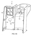
図2及び図93−96に示すように、排出接合部728は、流出被覆部744に接続しており、当該被覆部744は、収容室8の前側に位置している下側開口部746内に取り付けられており、かつ当該開口部746から一部延設された状態にある。
As shown in FIGS. 2 and 93-96, the discharge
流出被覆部744は、円錐台型コップ状壁部748を備えており、当該壁部748は、環状底側壁部750によって下側端の一部は、閉鎖された状態にある。
The
当該環状底側壁部750は、中央開口部752を備えているが、当該中央開口部752を貫通した状態にて、排出接合部728の中央突起736が延設されている。
The annular bottom
このような延設によって、調合飲料が受け台754(図1)上に位置しているコップ又は同様の形態物に提供されている。 With such an extension, the blended beverage is provided in a cup or similar form located on the cradle 754 (FIG. 1).
前記受け台754は、複数の穴756を備えており、かつT字型中空状周囲壁部26の前面に位置している平板状コップ支持部40上に載置されている。
The
円錐台型コップ状壁部748及び環状底側壁部750は、下側開口部746から延設されている。
The frustoconical cup-shaped
流出被覆部744は、中央開口部752の両側に相向かい合う2個の突起部758を有している。
The
前記突起部758は、排出接合部728の接続翼状部732とネジ(図示せず)を介して結合するための突出開口部760を有している。
The
前記ネジは、排出接合部728の開口部734を介して伸長し、かつ突出開口部760を貫通している。
The screw extends through the opening 734 of the discharge joint 728 and passes through the
流出被覆部744は、点対称状に相向かい合っている支持翼状部761を備えており、当該翼状部761は収容室8の前側面の頂部に当着している。
The
穴を有している2個の隆起型中空状基台762は、ネジ(図示せず)によって、流出被覆部744を収容室8に結合するための開口部764を有しており、当該ネジは、収容室8の前側端表面の上側に位置している突起部768内の突出開口部766内を貫通した状態にて伸長している。
The two raised
調合作業の間に、ユーザーは、移動可能な調合室機構538内における調合原料に対する乱流を伴う攪拌作用を、当該機構538の透明な一部球型区画578及び前側被覆部378の透明な半球状屋根状部388を介して注視することができる点が着目されねばならない。
During the compounding operation, the user can perform a turbulent stirring action on the compounding material in the movable
但し、前記機構538内の加熱水の熱によって、透明な半球状屋根状部388及び/又は透明な一部球型区画578は、霧が充満した状態と化し、前記のような乱流を伴う攪拌作業に対する目視が妨げられる場合がある。
However, the heat of the heated water in the
本発明においては、送風器774(図43及び84)は、回転軸362の後方及び下方に配置されている。
In the present invention, the blower 774 (FIGS. 43 and 84) is disposed behind and below the
テーパ状送風器導入接合部776(図97)は、送風器774の出力側と結合しており、当該接合部776の開口出力側端は、回転軸362の真下の位置を端部としている。 このような配置の目的は、透明な半球状屋根状部388と透明な一部球型区画578の間の空間に調合作業中空気を吹き付けることにある。
The tapered blower introduction joint 776 (FIG. 97) is coupled to the output side of the
このような吹き付けによって、透明な半球状屋根状部388及び/又は透明な一部球型区画578が調合作業中に霧が充満した状態に至ること、又は結露することを防止することができる。
Such spraying can prevent the transparent
送風器774に代えて、又はこれに加えて、例えば加熱ワイヤー又は類似の物を使用している加熱器(図示せず)もまた採用可能であって、その場合には、屋根状部388及び一部球型区画578の一方又は双方に対し霧が充満した状態の発生を防止する温度を提供することになる。
Instead of or in addition to the
調合作業を開始し、かつ制御するために、調合飲料供給装置2は、既に説明したマイクロプロセッサー702、映像表示部778及び制御用把手又はボタン782を備えている。
In order to start and control the blending operation, the blended
前記映像表示部778は、収容室8内の開口部780を介して目視することができ、前記制御用把手又はボタン782は、収容室8内の開口部784を介して延設されている。
The
マイクロプロセッサー702は、第1電磁弁686及び第2電磁弁724、水ポンプ172、水を加熱するヒータ192、空気ポンプ206、送風器774及び映像表示部778に接続されており、これらの作動に対する制御を行っている。
The
そして、制御用把手又はボタン782は、マイクロプロセッサー702における制御を操作しており、当該制御の結果は、映像表示部778によって表示されている。
The control handle or
しかも、映像表示部778は、マイクロプロセッサー702の制御によって、水の温度、調合時間、移動可能な調合室機構538において設定された圧力、例えば調合作業が現在行われているか否かという前後状況、残る調合時間、更には、他のパラメータ等に関する情報の表示を行っている。
In addition, the
制御用把手又はボタン782においては、映像表示部778の映像表示状態に従ってボタンを押す操作と当該把手又はボタン782を回転する操作との結合によって前記制御に必要な作業が行われている。
In the control handle or
従って、例えば調合作業の開始段階においては、最初の映像に表示する要求に基づいて、ユーザーに対し、制御用把手又はボタン782の回転によって増減できる調合時間について問い合わせることができる。
Therefore, for example, at the start stage of the blending operation, the user can be inquired about the blending time that can be increased or decreased by the rotation of the control handle or the
従って、ユーザーは、所望の設定状態が実現され、しかもそのような状態が映像表示部778上に表示されている場合には、制御用把手又はボタン782を押せば良い。
Therefore, when a desired setting state is realized and such a state is displayed on the
他方、映像表示部に基づく操作によって、ユーザーは、例えば温度、圧力、お茶の葉の大きさ等の各設定を継続して実現することができる。 On the other hand, the user can continuously realize each setting such as temperature, pressure, tea leaf size, and the like by an operation based on the video display unit.
更には、ユーザーは、映像表示部778において、所望の調合原料につき、マイクロプロセッサー702の記録部に予め記録されている設定状態、例えば、予め既に記録されているか、又はユーザーの選択によって予め設定されているお茶の格別なタイプ等について表示させることができる。
Further, the user can set a desired preparation material in the
このように、既に記録されているか又はユーザーの選択に基づいて予め設定されたパラメータが存在するが、ユーザーは、これらのパラメータを自らの好みに応じて設定することができる。 In this way, there are parameters that are already recorded or preset based on the user's selection, but the user can set these parameters according to their preferences.
操作に際し、押圧ボタン282は、前側被覆部378を開放し、かつ開口状態とするために、内側に押圧される。
In operation, the
移動可能な調合室機構538の頂部屋根状被覆区画542は、底側コップ状区画540から隆起した状態に至り、例えば並みの大きさのお茶の葉のような調合原料が挿入された後に、前記頂部屋根状被覆区画542が閉鎖される。
The top roof-
次に、移動可能な調合室機構538は、お茶調合支持部406内に挿入される。
Next, the movable
このような配置によって、前記機構538の噴射開口部570は、お茶調合支持部406の水注入開口部420と密封状態に必要な整列状態に至り、その結果、加熱水を前記機構538内に噴入することができる。
With this arrangement, the
水タンク4は、被覆部106を外したうえで水を注入するか、又は当該タンク4自体を台所又は同様の場所に移動したうえで同様の注入を行い、かつ元の位置に戻すことによって、水の補充が行われている。
The water tank 4 is injected with water after removing the covering
水を補充させるために水タンク4を移動する場合には、水の散逸を防止するために、タンク弁120は、底側開口部114を閉鎖する。
When the water tank 4 is moved to replenish water, the
水タンク4がT字型中空状周囲壁部26内に挿入された場合には、タンク弁120は、弁作動部86の弁作動用突起部94によって開放状態に至り、その結果、底側開口部114を介して水が放流される。
When the water tank 4 is inserted into the T-shaped hollow
その後、ユーザーは、制御用把手又はボタン782による調合作業に必要なパラメータを設定し、かつ映像表示部778によって表示される方法に従って、当該把手又はボタン782を押すことによって調合を開始する。
Thereafter, the user sets parameters necessary for the blending operation using the control handle or
その際、第1電磁弁686は、水が移動可能な調合室機構538内にて補充される段階では、空気を当該機構538から散逸させるために、マイクロプロセッサー702によって開放状態に設定されている。
At that time, the first
他方、第2電磁弁724は、前記機構538から飲用液の散逸を防止する段階に至った段階では、マイクロプロセッサー702によって閉鎖状態に設定されている。
On the other hand, the second
しかも、水ポンプ172は、マイクロプロセッサー702の制御によって水タンク4から水を加熱するヒータ192を介して水を移送しているが、当該ヒータ192もまたマイクロプロセッサー702によって制御されている。
In addition, the
水を加熱するヒータ192によって加熱された水の温度は、当該ヒータ192の開閉時間及び当該ヒータ192内の加熱コイルを介した電流の程度によって左右される。
The temperature of the water heated by the
前記制御においては、水を加熱するヒータ192又は当該水の下流側に温度センサー(図示せず)を設けたうえで、加熱水の温度につき、マイクロプロセッサー702に温度信号を伝達することが好ましい。
In the control, it is preferable to provide a temperature signal to the
水ポンプ172の作用によって、ヒータ192内にて加熱された水は、お茶調合支持部406の水注入開口部420、当該開口部420における各注入接合部524、及び移動可能な調合室機構538の楕円形状を呈しているコップ状体546内に形成されている噴射開口部570を貫通する状態にて圧力によって移送されている。
The water heated in the
各噴射開口部570は、やや内側を向くような角度方向に配置されており、当該角度方向の延長線は、頂部屋根状被覆区画542の頂部中央のやや下の位置である点571と交差している。
Each injection opening 570 is arranged in an angular direction that faces slightly inward, and the extension line in the angular direction intersects with a
このような配置の下に、噴出された加熱水の圧力を原因として、移動可能な調合室機構538内のお茶の葉又は他の調合原料に対して作用する渦流、及びより好ましくは、乱流を伴う攪拌状態を形成することができる。
Under such an arrangement, due to the pressure of the jetted heated water, vortices acting on the tea leaves or other ingredients in the movable
加熱水が、前記機構538を補充する段階では、当該機構538内の水位センサー(図示せず)がマイクロプロセッサー702に水位の信号を伝達している。
When heated water replenishes the
前記機構538が水によって補充されると同時に、前記機構内の空気は、第1電磁弁686を介して散逸し、しかもチューブ688、T字型接合部692、及びチューブ696を介して外気側に排出されている。
At the same time that the
移動可能な調合室機構538の頂部を介して飲用液を排出する段階では、当該飲用液は、第1電磁弁686、及びチューブ688、T字型接合部692及びチューブ700を通過して排出されている。
In the step of discharging the drinking liquid through the top of the movable
移動可能な調合室機構538内にて空気の排出を伴う当該機構538内の水の補充が所定のレベルに至ったことを水位センサーが感知した場合には、第1電磁弁686が閉鎖される。
When the water level sensor senses that the replenishment of water in the movable
この段階では、閉鎖された第1電磁弁686と前記機構538の開口した頂部との間の空間領域には、空気及び/又は水が残留している。
At this stage, air and / or water remains in the spatial region between the closed
前記機構538を水が更に補充された段階では、前記空間領域に移動した空気は加圧され、その結果、当該機構538の頂部から水が散逸することを防止する一方、当該機構538内の加熱水に対する加圧に寄与することになる。
When the
しかも、このような加圧状態によって、加熱水を補充する期間中、前記機構538の上側端における空気又は水蒸気の進入を封鎖することができる。
In addition, such a pressurized state can block the entry of air or water vapor at the upper end of the
前記機構538内において、加熱水を、所定の傾斜角度に沿って噴射し、かつ加圧することによって、加熱水は、調合物内に効率的に進入し、特に当該物がお茶の葉である場合には、お茶の葉から効率的に風味を抽出することができる。
In the
しかも、前記機構538内に注入された加熱水に対する乱流を伴う攪拌が行われた場合には、調合物と加熱水とが良好な混合状態に至り、調合物から更に効率的な風味の抽出が可能となる。
Moreover, when stirring with turbulent flow with respect to the heated water injected into the
前記混合の段階では、水ポンプ172は、前記機構538に対する水の供給動作を継続している。
In the mixing stage, the
但し、加熱水が充満するような容量に達した場合には、水ポンプ172は、専ら前記機構538内の加熱水に対する加圧作用に終始し、その結果、当該水と調合原料との相互作用は更に促進されることになる。
However, when the capacity is reached such that the heated water is filled, the
十分な調合時間が経過し、その結果、調合物から風味が十分抽出されるに至った段階では、第2電磁弁724が開口し、かつ排出接続部728の中央突起736に調合飲料が少しづつ供給され、更には、調合飲料は、受け台754上に位置しているコップ又は同種類の容器に供給されることになる。
When sufficient blending time has elapsed, and as a result, the flavor has been sufficiently extracted from the blend, the second
上記調合時間は、滞留時間、即ち水が排出されるに至るまでに、調合原料と接触状態にある時間の長さ、又は攪拌時間、即ち水及び調合原料が相互に攪拌状態となっている時間の長さによって左右される。 The blending time is the residence time, that is, the length of time in contact with the blended raw material until the water is discharged, or the stirring time, that is, the time during which water and the blended raw material are in a state of stirring each other. Depends on the length of the.
調合時間中、加熱水は、移動可能な調合室機構538に依然として供給されている。
During the compounding time, heated water is still supplied to the movable
例えば、仮に当該機構538が2オンス分の容量しか有していないのに対し、コップ又は水差しにおける所望の容量が8オンスである場合には、加熱水の供給は、必要な量だけ継続されることになる。
For example, if the
十分な量の加熱水が供給された場合には、マイクロプロセッサー702は、水ポンプ172の作動を閉鎖するような制御を行う。
When a sufficient amount of heated water is supplied, the
当該制御と同時に、マイクロプロセッサー702の作用によって、空気ポンプ206が前記機構538の一部切断タイプの球型コップ状体546内に形成されている噴射開口部570を介して空気を移送している。
Simultaneously with the control, by the action of the
このような空気の移送は、前記機構538から調合飲用液を流出するような空気圧を形成すること、及びT字型の接続部202及び噴射開口部570に至るまでの一連の流通ラインから飲用液を排出しながら清掃するという双方の目的に寄与している。
Such an air transfer forms an air pressure that causes the prepared drinking liquid to flow out of the
換言するならば、強制的に移送されている空気は、前記機構538内の飲用液を介して上昇し、当該機構538の頂部に至り、その結果、当該空気は、前記機構538から調合飲用液を排出することに寄与している。
In other words, the forcibly transferred air rises through the drinking liquid in the
強制的に移送されている空気は、例えば、34°F(華氏34度)のような調合飲料を冷却し、かつ凍結させないような温度にするとよい。 The air being forcibly transferred may be, for example, a temperature such as 34 ° F. (34 degrees Fahrenheit) that cools and does not freeze the blended beverage.
このような冷却空気は、アイスティー、アイスコーヒー又は同様の冷却された飲料を調合するために供給されている。 Such cooling air is supplied to formulate iced tea, iced coffee or similar cooled beverages.
空気ポンプ206が作動している前記時期においても、第1電磁弁686は、依然として閉鎖されており、その結果、移動可能な調合室機構538の頂部開口端と当該第1電磁弁686間にて加圧された空気は、前記機構538から調合飲料を押し出すことに寄与している。
Even at the time when the
調合飲用液が前記機構538から押し出された場合には、第1電磁弁686が再び開口する一方、第2電磁弁724が閉鎖する。
When the mixed drinking liquid is pushed out from the
そして、押圧ボタン282は、前側被覆部378を開放し、かつ開口するために内側に押され、その結果、移動可能な前記機構538は、他の調合作業のために除去されることになる。
The
本発明においては、特許請求の範囲(クレーム)の範囲内において、様々な変形がある。 The present invention has various modifications within the scope of the claims.
例えば、押圧ボタンによる施錠機構に代えて、図98に示すような回動型施錠機構786もまた採用することができる。
For example, instead of a locking mechanism using a push button, a rotation
回動型施錠機構786は、調合上側支持部316の前方から外側に延設されている突起部788を備えており、当該突起部788は、アーチ型の溝部790を有している。
The rotation-
他の突起部792は、調合下側支持部208の前面から外側に延設されており、直交する方向に延設されているピン794を備えている。
The
施錠ハンドル796は、一方端にて、ピン794によって軸支されており、U字型ワイヤー留金798は、下側自由端800を有している。
The locking handle 796 is pivotally supported at one end by a
前記下側自由端800は、ピン794の下側の位置にて内側に向かう状態を形成し、かつ施錠ハンドル796の側部を軸支した状態にて取り付けられている。
The lower
このようにして、調合作業の段階にて施錠する場合には、施錠ハンドル796は、ピン794の軸支の下に上側に回動し、しかも、U字型ワイヤー留金798は、アーチ型の溝部790内に配置されている。
In this way, when locking at the stage of the blending operation, the locking
しかも、施錠ハンドル796は、ピン794の軸支の下に下側に回動し、調合作業の段階では、調合下側支持部208及び調合上側支持部316を施錠することができる。
In addition, the locking
浮上センサーが水タンク4内に組み込まれ、ユーザーに対し、更に水を加えるべきであるという情報を提供するという好ましい変形による実施形態を採用することができる。 A preferred variant embodiment can be employed in which a levitation sensor is incorporated in the water tank 4 to provide the user with information that more water should be added.
前記浮上センサーは、マイクロプロセッサー702と接続し、しかもユーザーに対し、映像表示部778を介して情報を提供することが好ましい。
The floating sensor is preferably connected to the
このような場合、仮に、浮上センサーが装置2が作動するには水が不十分であると判定した場合には、マイクロプロセッサー702は装置2における故障を防止するために、当該装置2の作動を中止させることになる。
In such a case, if the levitation sensor determines that there is insufficient water for the
調合室機構538は、必ずしも移動可能である必要はなく、寧ろ所定の位置に固定することも可能である。
The mixing
これまで水を、調合物と混合する液体として説明を行っているが、本発明は、そのような構成に限定されている訳ではなく、他の適当な液体を利用することができる。 So far, water has been described as a liquid to be mixed with the formulation, but the present invention is not limited to such a configuration and other suitable liquids can be utilized.
例えば、アルコール、油等を調合原料から風味又は活性要素を抽出するための液体として使用することができる。 For example, alcohol, oil or the like can be used as a liquid for extracting a flavor or an active element from a blended raw material.
更には、第1電磁弁686は、流出頭部638に置換して利用することができる。
Furthermore, the first
上記置換の根拠は、透明半球状屋根状部388及び574を目視した場合に動的(ダイナミック)な動きによる審美的効果を発揮し得ることにある。
The basis for the replacement is that an aesthetic effect due to dynamic movement can be exhibited when the transparent
噴霧器900(図3)を排出接合部728の下端に設けるという更に変形した実施形態の場合には、お茶が軸状排出開口部738から排出する際、噴霧器900が飲用液であるお茶を霧のような液滴に細分化することができる。
In the case of a further modified embodiment in which the sprayer 900 (FIG. 3) is provided at the lower end of the discharge joint 728, when the tea is discharged from the
その結果、加熱されたお茶は、急速に冷却され、氷を備えたグラス内に供給することができる。 As a result, the heated tea can be rapidly cooled and fed into a glass with ice.
その根拠は、液滴状となったお茶のより大きな表面積によって外気に晒された場合には、急速に冷却されることにある。 The reason is that when exposed to the open air due to the larger surface area of the tea droplets, it is cooled rapidly.
しかも、お茶が氷と接触する前に、相当程度冷却しているため、お茶は、グラス内の氷を完全に溶かす訳ではない。 Moreover, the tea does not completely melt the ice in the glass because it is cooled to a considerable extent before it comes into contact with the ice.
噴霧器900は、通常採用されている噴霧器であれば、どのような形態であっても採用することができる。 The sprayer 900 can be used in any form as long as it is a sprayer that is usually employed.
噴霧器900としては、例えば液状飲用物が通過することによって、微細な噴霧状態とするような微細な孔を備えた遮蔽物(図示せず)という単純な構成も採用可能である。 As the sprayer 900, for example, a simple configuration of a shielding object (not shown) provided with a fine hole that allows a liquid drink to pass through to make a fine spray state can be employed.
このような構成とは別に、例えば、噴霧器900は、良く知られているベンチュリ効果を利用することもできる。 Apart from such a configuration, for example, the nebulizer 900 can also use the well-known Venturi effect.
その場合には、気体が順次断面積が減少するようなチューブ又はベンチュリ管を所定の圧力の下に噴出される際、噴出速度が上昇し、所謂ベルヌーイの定理によって最も断面積が小さい位置において圧力が低下している。 In that case, when a gas or a tube with a reduced cross-sectional area is sequentially ejected under a predetermined pressure, the ejection speed increases, and the pressure at the position where the cross-sectional area is the smallest according to the so-called Bernoulli theorem. Has fallen.
このような圧力低下によって、飲用液が存在する場所との圧力の相違が発生し、飲用液は、収容室形成用胴部側から吸収されるか、又は前記胴部側から流出し、チューブのうちの最も狭い領域を介して流動している気流中に流動し、微細な噴霧状態の液滴となって噴出され、通常使用されている香水に対する噴霧器と同じような状態を呈することになる。 Due to such a pressure drop, a difference in pressure from the place where the drinking liquid is present occurs, and the drinking liquid is absorbed from the storage chamber forming body side or flows out of the body side, It flows into the air stream flowing through the narrowest region, and is ejected as fine sprayed droplets, which are in the same state as a sprayer for perfume normally used.
本出願発明における屋根型に関しては、透明であることを必要とするが、特に部分的な球状形態に限定される訳ではなく、どのような形状及び大きさであっても良い。 The roof mold in the present invention needs to be transparent, but is not particularly limited to a partial spherical shape, and may have any shape and size.
図99−110は、更に変形調合飲料供給装置1002を開示している。
FIGS. 99-110 further disclose a modified blended
上側の軸支された機構として、押圧ボタン282に代えて、旋回ハンドル機構1004が設けられており、その場合には、調合機構6は施錠の対象とならない。
As a mechanism supported on the upper side, a
即ち旋回ハンドル機構1004は、概略U字型ハンドル1006を備えており、しかも当該ハンドル1006は、面接状自由端1008を有している。
That is, the turning
接続棒1010は、ネジ1111によって、ハンドル1006の面接状自由端1008の間に固着されており、当該接続棒1010は、変形調合上側支持部1014(図107及び108)から延設されているU字型棒支持部1012上に旋回可能な状態にて当着している。
The connecting
2個のZ字型押付部材1016は変形調合上側支持部1014と結合しており、それぞれアーム1016aを有している。
The two Z-shaped
前記アーム1016aは、接続棒1010の上側の位置にて、U字型棒支持部1012を横断する状態にて設置されており、かつ接続棒1010の係着位置からの離脱を防止している。
The
従って、接続棒1010は、変形調合上側支持部1014に接続されていることに基づき、上側方向に隆起しており、かつ変形調合上側支持部1014が当該支持部1014の後部に位置している耳部1017を軸とする旋回を可能とし、当該旋回の結果、移動可能な調合室機構の挿入及び移動が実現可能となる。
Therefore, the connecting
図107に示すように、変形調合上側支持部1014は、前方端中央にて、下側延長凹部1018を備えている。
As shown in FIG. 107, the deformation blending
前記凹部1018は、下側延設後側壁部1020、下側延設前側壁部1022、これらの壁部1020及び1022と接続し、かつ相向かい合う状態にて下側に延設されている側方壁部1024、及びこれらの壁部1020、1022、1024と接続している底側壁部1026によって構成されている。
The
U字型棒支持部1012は、凹部1018の後端であって、後側壁部1020の前側に位置している側方壁部1024の外側に配置され、かつ上側に延設されており、その結果、接続棒1010は、凹部1018上に架設されている。
The U-shaped
図104に示すように、相互に所定の空間領域を介して離れた状態にある2個の耳部1028は接続棒1010から下側に延設され、当該延設位置にて旋回可能な状態にある。
As shown in FIG. 104, the two
耳部1028は、U字型棒支持部1012の内側となるように配置されている。
The
その根拠は、耳部1028が凹部1018と僅かな距離を形成するように下側に延設されており、しかも後側壁部1020の前側に配置され、かつ凹部1018の各壁部と接触せずに旋回又は回転することが必要とされていることにある。
The grounds are that the
軸頭棹部材1030は、耳部1028の下側端の間にて接続されており、連接部材1032(図105)は、前記軸頭棹部材1030に軸支されている。
The
連接部材1032は、上側軸頭区画1034、下側軸頭区画1036、及び接続区画1035を備えており、当該接続区画1035は、上側軸頭区画1034を上側としたうえで、下側軸頭区画1036に接続している。
The connecting
2個の上側軸頭区画1034は、同軸状態であって、かつ相互に離れた状態にある筒状載置部1038を備えており、当該載置部1038は、軸頭棹部材1030によって旋回可能な状態にて軸支されている。
The two
前記軸支において、接続区画1040は、前記筒状載置部1038を相互に接続すると共に、軸頭棹部材1030を部分的に囲んだ状態にある。
In the shaft support, the
2個の下側軸頭区画1036は、同軸状態であって、相互に離れた状態にある筒状載置部1044を備えており、当該載置部1044は、接続区画1042によって相互に接続されており、しかも軸頭棹部材1046によって旋回可能な状態にて軸支されている。
The two lower
旋回鉤部1048(図106)は、連接部材1032の筒状載置部1038の外側にて軸頭棹部材1046の端部上に取り付けられている。
Turning hook 1048 (FIG. 106) is mounted et the on the end of
各旋回鉤部1048は、L字型鉤部材1050を備えており、当該部材1050は、接続腕1052及び当該接続腕1052の下側端から直交する状態にて延設されている鉤腕1054を有している。
Each
鉤腕1054は、その前後の両側端において湾曲端部1054aを有している。
The
開口部1058を有している第1旋回小耳部1056は、接続腕1052の上側端に接続され、鉤腕1054の真上に配置されている。
The first turning
第2の作動小耳部1060は、第1接続腕1052の上側端から後方に延設されており、しかも軸頭棹部材1046の一方端が延設され、かつ貫通している開口部1062を有している。
The second working
各L字型鉤部材1050は、変形調合上側支持部1014における凹部1018の底側壁部1026内の溝穴1064を貫通して延設されており、その結果、鉤腕1054は、底側壁部1026の下側に配置されている。
Each L-shaped
先端軸頭1066は、2個の旋回鉤部1048における第1旋回小耳部1056の開口部1058を貫通して延設されており、先端軸頭1066の相向かい合う端部は、変形調合上側支持部1014の前方における半筒状凹部1068に配置されている。
The
先端軸頭1066が半筒状凹部1068内に配置されている場合には、Z字型押付部材1016における相向かい合うアーム1016bが先端軸頭1066の端部にまで延設されており、当該押付部材1016の当該先端軸頭1066からの逸脱を防止している。
When the
コイル状バネ1069は、前記支持部1014において下方に延設されている側方壁部1024及びL字型鉤部材1050の間にて先端軸頭1066の各端部に捲着しており、旋回鉤部1048に対して前方及び後方に旋回させようとする力に対し、所定位置に留ませるように作用する圧力を発揮している。
The
図108、109及び110に示すように、変形調合下側支持部1070は、変形調合上側支持部1014における凹部1018の底側壁部1026内の溝穴1064と整列状態を呈している。
As shown in FIGS. 108, 109, and 110, the deformation blend
その結果、鉤腕1054もまた、前記開口部1072を貫通して変形調合下側支持部1070の下方まで延設されている。
As a result, the
変形調合上側支持部1014の下面は、一部筒状凹部1074を備えており、当該凹部1074は、開口部1072と直角方向に交差しており、かつ当該開口部1072は、前記凹部1074と開口部を介して接続している。
The lower surface of the deformation blending
抑制ピン1076は、一部筒状凹部1074内にて、例えば溶接棒、接着剤、ネジ、下方支持部材のような適当な媒介手段によって固着されている。
The
変形調合飲料供給装置1002が施錠段階又は作業段階にある場合には、鉤腕1054は、抑制ピン1076と共に旋回し、かつ変形調合上側支持部1014を変形調合下側支持部1070に施錠している。
When the modified blended
コイル状バネ1069は、鉤腕1054における動揺を防止している。
The
しかしながら、U字型ハンドル1006が押圧された場合には、当該ハンドル1006は、接続棒1010を1009に示す矢印の方向(図103)に旋回させ、耳部1028もまた、同一方向である前方に回転することになる。
However, when the
その結果、連接部材1032の上側軸頭区画1034もまた、耳部1028と共に前方に旋回するが、その原因は、当該区画1034が軸頭棹部材1030を介して耳部1028に接続していることにある。
As a result, the
このような作動の結果、連接部材1032の下側軸頭区画1036は、後方に旋回し、かつ軸頭棹部材1046を一体状態にて移動させている。
As a result of such an operation, the
旋回鉤部1048における作動小耳部1060は、前記軸頭棹部材1046上に取り付けられていることから、前記のように軸頭棹部材1046は自らの移動を原因として、第2の作動小耳部1060を後方側に引くように作用し、その結果、先端軸頭1066に軸支されている旋回鉤部1048は、コイル状バネ1069による弾性力に逆らって旋回している。
Actuating overheard
このような作動を原因として、L字型鉤部材1050は、抑制ピン1076から解放され、その結果、変形調合上側支持部1014は、変形調合下側支持部1070から上側に旋回することになる。
Due to such an operation, the L-shaped
このような配置状態の下に、調合室機構に対する除去又は挿入を実現することができる。 Under such an arrangement, removal or insertion into the blending chamber mechanism can be realized.
閉鎖状態の作業の段階では、ハンドル1006は、下側に押圧され、その結果、変形調合上側支持部1014は下側に旋回し、変形調合下側支持部1070に接近することになる。
At the stage of the operation in the closed state, the
この段階では、接続棒1010が矢印1009と反対方向に旋回し、かつ耳部1028もまた、同一方向に沿って後側に回転する。
At this stage, the connecting
その結果、連接部材1032の上側軸頭区画1034は、耳部1028と共に後側に旋回するが、その原因は、当該区画1034が軸頭棹部材1030を介して耳部1028に接続していることにある。
As a result, the
このような作動を原因として、連接部材1032の下側軸頭区画1036が前方に旋回し、更には軸頭棹部材1046もまた一体となって旋回移動を行うことになる。
Due to such an operation, the
旋回鉤部1048の作動小耳部1060が前記軸頭棹部材1046上に取り付けられていることから、前記のように、軸頭棹部材1046が旋回移動を行うことによって、第2作動小耳部1060が前方に押されるという効果が発生する。
Since actuating overheard 1060 of the
その結果、先端軸頭1066に軸支されている旋回鉤部1048はコイル状バネ1069による弾性力に逆らって旋回することになる。
As a result, the
変形調合上側支持部1014に対する下側への移行を継続している段階では、L字型鉤部材1050は、抑制ピン1076と係合し、その結果、変形調合上側支持部1014は、変形調合下側支持部1070と結合している。
At the stage where the transition to the lower side with respect to the deformation blending
L字型鉤部材1050が、抑制ピン1076の下側にて係合する前に、前方の位置に移動している段階では、変形調合上側支持部1014の後方への移動の継続を原因として、鉤腕1054の湾曲端部1054aは、抑制ピン1076上に乗り上げ、鉤腕1054は抑制ピン1076を離脱させる状態に至るまで後方に押圧されている。
Before the L-shaped
従って、鉤腕1054が下側への移行を継続した後には、抑制ピン1076との施錠関係を解消することになる。
Therefore, after the
コイル状バネ1069は、一方端において1個の旋回鉤部1048と結合するか、又は他方端において、収容室と結合しており、その結果、コイル状バネ1069は、施錠による配置状態の段階では、旋回鉤部1048に対し前方に回転させるような回転力を発揮している。
The
従って、ハンドル1006を上側に回転させた段階では、旋回鉤部1048は、コイル状バネ1069による弾性力に逆らって後方に移動し、装置を開口状態とすることになる。
Therefore, at the stage where the
これに対し、ハンドル1006の上方への移動を解除した段階では、旋回鉤部1048は、前方の位置に向かって回転することになる。
On the other hand, at the stage where the upward movement of the
従って、閉鎖状態による作動の段階では、旋回鉤部1048は、コイル状バネ1069によって前方の位置に向かうように付勢され、鉤腕1054の湾曲端部1054aは、抑制ピン1076上に乗り上げ、かつ鉤腕1054が抑制ピン1076から離脱するに至るまで、後方への圧力を受けることになる。
Accordingly, in the stage of operation due to the closed state, the
その結果、鉤腕1054の下方における移行状態が継続した次の段階では、コイル状バネ1069による弾性力によって鉤腕1054は、抑制ピン1076との施錠関係を解消することになる。
As a result, at the next stage where the transition state below the
更には、図111−116に示すように、変形調合飲料供給装置1002においては、ヒンジ部544に軸支された状態にて開口する移動可能な調合室機構に代えて、変形された移動可能な調合室機構1080を採用することができる。
Furthermore, as shown in FIGS. 111 to 116, in the modified mixed
前記機構1080は、底部側コップ状区画1082及び頂部側屋根状被覆区画1084を備えている。
The mechanism 1080 includes a bottom cup-shaped
これらの区画は、中央における垂直方向軸の周囲にて相互に回転するか又はねじれ状態を形成すると共に、バヨネット施錠機構1086によって、相互に施錠状態を実現することができる。
These sections rotate or twist around each other around a vertical axis at the center and can be locked together by a
移動可能な調合室機構1080において形成された圧力を考慮するならば、当該機構1080は、前述の旋回鉤部1048における通常の施錠システムに加えて、第2の施錠システムを実現している。
If the pressure formed in the movable preparation chamber mechanism 1080 is taken into consideration, the mechanism 1080 implements a second locking system in addition to the normal locking system in the
底部側コップ状区画1082は、一部切断タイプの球型コップ状体1088を備えており、当該コップ状体1088は、上側端にて外側に延設されている環状壁部1090を備えており、当該環状壁部1090の更なる外側端からは、上側に延設され、かつ環状直立周囲壁部1092が形成されている。
The bottom-side cup-shaped
環状突起部1094は、前記環状壁部1090の内側端から上側に延設されており、当該環状壁部1090との間にて、環状凹部1096が形成されており、その結果、図61に示すゴム製リング510と同様のゴム状の遮蔽リングを支持することができる。
The
三等分に配分された環状枠1098は、環状直立周囲壁部1092から外側に延設されている。
The
各環状枠1098は、上側アーチ型壁部1100、側方壁部1102、及び外側アーチ型壁部1104を備えている。
Each
前記上側アーチ型壁部1100は、上側端にて、前記環状直立周囲壁部1092と同一平面上に位置しており、前記側方壁部1102は、前記底部側コップ状区画1082の半径方向に沿っており、かつ前記上側アーチ型壁部1100の相互に向かい合う側部にて前記周囲壁部1092の外側面と接続し、前記外側アーチ型壁部1104は、前記アーチ型壁部1100の外側端及び前記側方壁部1102の外側端と接続している。
The upper
このような配置構成の下に、三等分の状態にて配置されている環状枠1098の間に三等分に配置された開口領域1106が形成されている。
Under such an arrangement, an
細長ハンドル1108は、前記環状枠1098のうちの1個から外側に延設されており、当該ハンドルは、アーチ型壁部1100と同一平面を形成している平坦面1110を有している。
The
このようなハンドル1108によって、ユーザーは、調合作業の後に、お茶の調合支持部から移動可能な調合室機構1080を除去すると共に、当該機構1080を当該支持部に挿入し、調合作業を開始することもできる。
With such a
バヨネット施錠機構1086は、各開口領域1106の下側端において限界縁部1112を備えており、しかも各開口領域1106に対し、約1/2の角度範囲に延設されている。
The
限界縁部1112は、各開口領域1106の間に延設されている環状壁部1090と同一平面にあり、かつ当該壁部1090から延長した領域を形成している。
The
上側施錠縁部1114は、各開口領域1106の上側端に形成されており、かつ限界縁部1112に隣接し、しかも開口領域1106の角度範囲に比し、約1/2の角度範囲を形成している。
The
上側施錠縁部1114の上側面は、上側アーチ型壁部1100と同一平面を形成し、かつ開口領域1106内に延設されている。
The upper side surface of the upper
V字型突起部1116は、各上側施錠縁部1114の下端側から延設され、延設側端は自由であって、他の構成要素に接続していない。
The V-shaped projecting
底部側コップ状区画1082の他の構成要素は、実質的には、底側コップ状区画540の場合と同一であって、更なる説明については省略する。
The other components of the bottom side cup-shaped
頂部側屋根状被覆区画1084は、屋根状部1120を備えており、当該屋根状部1120は、ガラス又はプラスチック製の透明部分的球状区画1124によって、上側端が閉じられている下側筒状区画1122を有している。
The top
開口部1126は、部分的球状区画1124の上側中央部に形成されている。
環状縁部1128は、筒状区画1122の下側端から外側に延設されている。
The
直交環状壁部1130は、環状縁部1128の下側面から下側に延設されており、しかも下側筒状区画1122の下側端よりも大きな径を有している。
The orthogonal
直交環状壁部1130の径は、底部側コップ状区画1082と頂部側屋根状被覆区画1084とが相互に嵌合し合う場合に、当該環状壁部1130が環状凹部1096内の直立周囲壁部1092の領域内に収納されるように設計されている。
The diameter of the orthogonal
前記の点に関連し、4個の等角度にて相互に離れた状態にて配分された下方押圧部材1132が直交環状壁部1130の内側面に形成されており、かつ環状凹部1096に配置されているゴム状遮蔽部を押圧する機能を発揮している。
In relation to the above point, four downward pressing
ハンドル1134は、環状縁部1128の下側面に位置している直交環状壁部1130の外側面から半径方向に沿って延設されており、平坦下側面1136を有している。
The
前記下側面1136は、細長ハンドル1108の上側平坦面1110と相互に面接し合うことによって、閉鎖された状態にて作動し得る配置状態が形成されている。
The
バヨネット施錠機構1086は、更に環状縁部1128の外側端から下側に延設されており、かつ3個の等角度に配分された交差凸部1138を備えている。
The
交差凸部1138は、アーチ型壁部1140、下側保持壁部1142、止着壁部1144を備えている。
The intersecting
前記アーチ型壁部1140は、環状縁部1128の外側端から下側に延設されており、前記下側保持壁部1142は、前記各アーチ型壁部1140の下側端から内側に半径方向に沿って延設されており、前記止着壁部1144は、前記各アーチ型壁部1140の一方側端部から内側に延設され、しかも各下側保持壁部1142の一方端からやや上側に配置されている。
The
頂部側屋根状被覆区画1084の他の構成要素は、頂部屋根状被覆区画542の構成要素と実質的に同一であることから、これらの詳細な説明については省略する。
The other components of the top
かくして、調合作業に際し、変形された移動可能な調合室機構1080を閉鎖状態とするためには、頂部側屋根状被覆区画1084の環状縁部1128は、底部側コップ状区画1082のアーチ型壁部1100上に配置され、その結果、図116に示すように、交差凸部1138は、下側の限界縁部1112の上側に配置される。
Thus, in order to close the deformable movable blending chamber mechanism 1080 during the blending operation, the
次に、頂部側屋根状被覆区画1084を底部側コップ状区画1082に対し、図116に示す矢印と反対方向に相対的に回転させることによって、図115に示すような配置状態とすることができる。
Next, the top-side roof-
その結果、各下側保持壁部1142は、V字型突起部1116を下側とするような位置に移動してから下側に落下し、しかも当該突起部1116の位置を通過した場合には、当該突起部1116を下から支えることになる。
As a result, each
このような配置状態においては、V字型突起部1116は、下側保持壁部1142と止着壁部1144との間に確保されることになる。
In such an arrangement state, the V-shaped projecting
変形された移動可能な調合室機構1080を開放状態とするためには、底部側コップ状区画1082及び頂部側屋根状被覆区画1084に対し、図115及び116の方向に沿った回転と逆方向の回転作業を行うことになる。
In order to open the deformable movable mixing chamber mechanism 1080, the bottom cup-shaped
変形調合飲料供給装置1002においても、既に説明したように、頂部側屋根状被覆区画1084の部分的球状区画1124は、頂部屋根状被覆区画542の一部球型区画578の場合と同様に透明であり、しかも半球状屋根状部388もまた透明である。
Also in the modified blended
従って、図100において詳細に示すように、2個のLED照明機構1146が相互に約90度の角度を以って相向かい合った状態にて部分的球状区画1124の側部に配置されている。
Accordingly, as shown in detail in FIG. 100, two
前記機構1146は、前記区画1124を通過するような白色光を照射する白色LED照明を備えている。
The
このような配置状態によって、ユーザーは、移動可能な調合室機構538及び1080内において発生している渦流及び攪拌による乱流を目視することができる。
By such an arrangement state, the user can visually observe the vortex flow generated in the movable
第1実施形態において、既に説明したように、変形しないチューブ650、第2空気室筒状部658及び空気循環接続部668を介して最初に流出する飲用液は、当初の調合作業の段階では、チューブ684、第1電磁弁686及びチューブ688、T字型接合部692及びチューブ700を介して、配水管としての機能を発揮しているT字型中空状周囲壁部26に供給され、かつ排出されている。
In the first embodiment, as already described, the drinking liquid that first flows out through the
然るに、当初の調合作業の段階にて調合が完了していない状態にあるコーヒーのような飲用液は、大量のカフェインを含有しており、このような飲用液をどのように扱うかは重要なテーマとならざるを得ない。 However, drinking liquids such as coffee that have not been fully formulated at the beginning of the formulation process contain large amounts of caffeine, and how to handle such drinking liquids is important. It must be a unique theme.
この点を考慮し、図117に示すように、前述の各構成要素に代えて、空気循環接続部668の直交パイプ678に一方端を接続しているチューブ1150を設置し、調合が完了していない飲用液を第2の飲用液排出口、具体的には、第2お茶排出口1152に供給し、かつその下側に配置されている飲用液用のコップ、具体的には、お茶用のコップに提供するような構成も採用可能である。
In consideration of this point, as shown in FIG. 117, a
更なる変形形態として、図118及び119に示すように、更に変形頂部屋根状被覆区画1160を移動可能な調合室機構として採用する構成もまた存在する。
As a further variation, there is also a configuration that further employs a modified top
このような変形頂部屋根状被覆区画1160は、前述の米国特許出願No.14/140,189記載の原理を採用しており、その開示事項を、参考として、以下の通り説明する。
Such a deformed top roof-
上記各図に示すように、コップ状の浮上弁室1162は、上側開口部1166を囲んだ状態にある変形頂部屋根状被覆区画1160における透明部分的球状区画1164の下側面から延設されている。
As shown in the above figures, the cup-shaped floating
コップ形状の浮上弁室1162は、上側開口部1166の真下の位置にて、透明部分的球状区画1164の下側面に確保されている環状側方壁部1168及び閉鎖底側壁部1170を備えている。
The cup-shaped
少なくとも2個の小開口部1172は、空気を上側開口部1166を介して散逸させるために環状側方壁部1168に配置されている。
At least two
環状シリコンボール室1174は、コップ形状の浮上弁室1162の上端と嵌合している。
The annular
環状シリコンボール室1174は、上側開口部1166と流動自在である下側開口部1178を有しており、かつ下側に沿って縮小又は拡張している表面1176を備えている。
The annular
弁ボール1180は、コップ形状の浮上弁室1162内にて、前記縮小又は拡張した表面1176の真下に配置されている。
The
弁ボール1180は、ポリプロピレン又は他の浮上可能な素材によって製造されていることが好ましい。
The
弁ボール1180は、当初浮上弁室1162における閉鎖底側壁部1170上に配置されており、その結果、上側開口部1116は、外気に対して開放された状態にある。
The
但し、移動可能な調合室機構内にて水面が上昇するに従って、当該機構の上端における空気は小開口部1172及び上側開口部1166を介して上側に押圧され、その結果、前記機構に対する外気又は蒸気の進入を防止し、かつ前記機構内における水を必要な量に設定することができる。
However, as the water level rises in the movable mixing chamber mechanism, the air at the upper end of the mechanism is pushed upward through the
浮上弁室1162内において水面が所定のレベルに至った場合には、当該水は、小開口部1172を介して浮上弁室1162内に進入しており、その結果、浮上弁ボール1180は、当該水と共に上昇し、下側に沿って縮小又は拡張している表面1176と接触状態に至り、下側開口部1178を閉鎖することになる。
When the water level reaches a predetermined level in the
このような時期においても、加圧された加熱水は移動可能な調合室機構に対する流入を継続している。 Even in such a period, the pressurized heated water continues to flow into the movable mixing chamber mechanism.
前記機構が水によって完全に補充された段階では、前記機構内の圧力は、ポンプの押圧力と等しい状態に至っている。 When the mechanism is completely replenished with water, the pressure in the mechanism is equal to the pressing force of the pump.
このように、容器内の圧力が上昇している段階では、当該圧力はお茶の葉から風味を短時間にて抽出することに寄与している。 Thus, at the stage where the pressure in the container is rising, the pressure contributes to extracting the flavor from tea leaves in a short time.
しかも、前記移動可能な調合室機構が加圧され、しかも加熱水によって完全に補充しているというこの段階では、既に第1の実施形態に即して説明したように、お茶の葉に浸漬した加熱されたお茶が前記機構における底側のコップ状区画を介して、前記機構からの外側への放流と同等の割合にて新鮮な加熱水が前記機構内に流入している。 Moreover, at this stage in which the movable preparation chamber mechanism is pressurized and completely replenished with heated water, it has been immersed in tea leaves as already explained in connection with the first embodiment. Fresh heated water flows into the mechanism at a rate equivalent to the discharge of the heated tea through the cup-like compartment on the bottom side of the mechanism to the outside.
このような状態によって、所望のお茶を調合することができ、その結果、例えば、1グラス当り8オンス、又は1水差し又はポット当り32オンスという程度の量にすることができる。 Such conditions allow the desired tea to be formulated, resulting in an amount of, for example, 8 ounces per glass, or 32 ounces per jug or pot.
加圧された加熱水が移動可能な調合室機構内に進入することを終了した場合であっても、加熱水の浸漬を原因とするお茶は、前記機構からの排出を継続している。 Even when the pressurized heated water has finished entering the movable preparation chamber mechanism, tea caused by immersion of the heated water continues to be discharged from the mechanism.
前記移動可能な調合室機構内の水面が弁ボール1180のレベルよりも下側に至った場合には、弁ボール1180の浮上位置は低下し、更には閉鎖底側壁部1170上に配置され、その結果、上側開口部1166は外気に対して開放しているが、そのような開放状態は、残留した水の浸漬によるお茶が重力の作用によって前記機構から排出されることに寄与することになる。
When the water surface in the movable mixing chamber mechanism reaches below the level of the
各移動可能な調合室機構における頂部の屋根状被覆区画の上側の開口部584及び1126において、更なる変形による選択として、より小さい設計をすることによって、当該機構から散逸する空気の比率を限定することが可能であり、その結果、調合作業における圧力を増加させることができる。
In the
集約するならば、本発明は、コーヒーの調合に首尾よく使用することができる。 In summary, the present invention can be successfully used in coffee brewing.
但し、コーヒー豆の硬度は千差万別であって、この点においてお茶の葉と相違している。 However, the hardness of coffee beans varies widely and is different from tea leaves in this respect.
このため、コーヒーの調合の場合には、移動可能な調合室機構538又は1002における底側のコップ状区画の噴射開口部570を多数採用することから、そのサイズを小さく設計しなければならない。
For this reason, in the case of brewing coffee, a large number of
このような設計変更によって、前記機構に流入する飲用液の攪拌の程度及び圧力が減少し、かつ速度も小さい状態と化すが、圧力を増加することができる本発明は、上記設計変更に十分適合することができる。 Such a design change reduces the degree and pressure of stirring of the drinking liquid flowing into the mechanism and reduces the speed, but the present invention that can increase the pressure is well suited to the above design change. can do.
添付する図面に即して、本発明の好ましい実施形態を明らかにしたが、本発明は、これらの実施形態に限定される訳ではなく、当業者においては、後述する特許請求の範囲によって定義された発明の技術的範囲又は基本的技術思想の範囲内にて様々な変形及び修正による構成を採用することができる。 The preferred embodiments of the present invention have been clarified with reference to the accompanying drawings, but the present invention is not limited to these embodiments, and those skilled in the art are defined by the following claims. Various modifications and corrections can be adopted within the technical scope or basic technical idea of the present invention.
このように、本発明に係る既存のKEURIGによる装置において、既存のK−CUPの容器の技術的問題点を十分克服したうえで、効率的に飲用物の素材から風味を抽出することが可能であって、その利用価値は絶大である。 Thus, in the existing KEURIG apparatus according to the present invention, it is possible to efficiently extract the flavor from the material of the drink, while sufficiently overcoming the technical problems of the existing K-CUP container. And its utility value is tremendous.
2 調合飲料供給装置
4 水タンク
6 調合機構
8 収容室
10 前側基台
12 T字型の基礎部
14 T字型のスチール板
14a 板状主脚部
14b 中央脚部
16 コップ状吸着脚部
18 開口部
20 球状に膨らんだ端部
22 環状溝
24 アーチ型の対面吸着部
26 T字型中空状周囲壁部
27 筒状隆起壁部
28 側方壁部
29 中央突起状開口部
30 上側壁部
31 矩形状凹部領域
32 端部における水タンク支持部
34 中央水ポンプ及びヒータサポート
36 末端における空気ポンプ支持部
38 チューブに対する連結状態による支持部
40 コップに対する平坦状の支持部
42 突起
44 突出開口部
46 ネジ
48 開口部
50 乳首状の結合部
52 アーチ型の案内壁部
54 開口部
56 環状案内壁部
58 突起
59 突出開口部
60 水タンク接続部
62 環状側方壁部
64 底側壁部
66 中央の隆起状区画
68 中央の円筒状凹部
70 環状凹部
72 突起部
74 開口部
76 開口部
78 外側に向かって伸長している乳首状の結合部
80 外側に向かって伸長している乳首状の結合部
82 突起部
84 開口部
86 弁駆動部
88 環状壁部
90 円形の底側壁部
92 小開口部
94 弁駆動部突起部
100 水タンク周壁部
102 側方壁部
104 底側閉鎖部
106 除去可能な被覆部
108 側方壁部
110 上側壁部
112 周辺口部
114 中央開口部
116 環状の弁支持突起
120 タンク弁
122 環状底側リング
124 半径方向に延設されている壁部
126 中央支柱
128 中間環状ディスク
130 半径方向に沿った延設壁部
132 下側区画
134 上側区画
136 四分割された開口部
138 上側環状ディスク
140 直径が縮小した状態にある頸部
142 環状凹部
144 ガスケットリング
146 コイル状バネ
148 タンク注入リング
150 上側環状壁部
152 中央開口部
154 傾斜状環状壁部
156 外側環状側壁部
158 内側環状側壁部
160 環状凹部
162 支持テーブル
164 矩形テーブル頂部
166 支持脚部
168 円形突起部
170 開口部
172 水ポンプ
174 注入パイプ
176 変形可能なチューブ
178 流出パイプ
179 配管
180 片側方向弁体
181 注入口
182 第1ブラケット
184 第2ブラケット
186 流出口
188 迂回乳首状結合部
190 変形可能なチューブ
192 水ヒータ
194 注入口
196 変形可能なチューブ
198 流出口
200 変形可能なチューブ
202 T字型の接続部
204 変形可能なチューブ
206 空気ポンプ
207 調合支持機構
208 調合下側支持部
210 上側壁部
212 湾曲前側端
214 短い側方壁部
216 矩形状の切除区画
218 環状開口部
220 垂直下方延設案内壁部
222 内側に延設されている円形棚状部
224 下側延設案内壁部
226 凹部区画
228 下側凹状壁部
230 突出開口部
232 案内開口部
234 矩形状の凹部区画
235 耳部
236 矩形状の切除区画
237 軸方向整列開口部
238 側方壁部
240 底側壁部
242 保持壁部
244 細長状開口部
246 壁部
248 案内ポケット
250 筒状突起
252 突出上側開口部
254 コーナー棚状部
256 突出上側開口部
258 開口部
260 筒状突起
262 階段状貫通開口部
264 施錠機構
266 押圧ボタン機構
268 施錠板
270 平行脚部
272 接合脚部
274 中央の二分割された施錠脚部
276 上側傾斜面
278 バネ受け脚部
280 コイル状バネ
282 押圧ボタン
284 保持壁部
286 収納被覆板
288 開口部
290 鉤支持部
292 上側連結板
294 開口部
296 施錠板
298 施錠開口部
300 下側被覆部
302 上側壁部
304 湾曲前方端
306 狭幅の側方壁部
308 矩形状切除区画
310 円形開口部
312 突起
314 細長状開口部
316 調合上側支持部
318 下側壁部
320 湾曲前方端部
322 上側に狭幅状態にて延設されている側方壁部
324 湾曲把持ハンドル
326 円形開口部
328 垂直上側方向延設壁部
330 内側に延設された上側環状棚状部
332 円形開口部
333 直交開口区画
334 後方開口区画
336 後側島状区画
338 前側区画
340 凹状区画
342 小開口部
344 中央の後側凹状区画
346 小開口部
348 突起
350 開口部
351 突起
352 細長状開口部
353 突出開口部
354 耳部
356 開口部
358 小耳部
360 直交開口部
362 回転軸
364 第1交差腕
366 軸ピン
368 第2交差腕
369 軸ピン
370 第3交差腕
371 軸ピン
372 コイル状引張バネ
374 突起部
376 開口部
378 前側被覆部
380 上側壁部
382 湾曲前側端
384 上側方向に湾曲した後側矩形状壁部
386 中央開口部
388 透明な半球状屋根状部
390 突出状態を呈している下側環状部分
392 矩形状小開口部
393 T字型開口部
394 狭幅矩形状壁部
396 耳状壁部
398 側方壁部
400 矩形状切除区画
402 階段状突起
404 突出開口部
406 お茶調合支持部
408 部分的球形状である基礎壁部
410 環状棚状部
412 環状案内壁部
413 環状溝部
414 結合耳部
416 開口部
418 案内壁部
419 L字型凹部
420 水注入開口部
422 チューブ止着接続部
424 チューブ
426 注入口
428 T字型注入連結部材
430 第1流出突起
432 第2流出口
434 結合耳部
436 開口部
438 ネジ
440 突出開口部
442 突起
444 変形自在のチューブ
446 注入口
448 注入接合部
450 排出突起
452 結合耳部
454 開口部
456 ネジ
458 円形開口部
460 環状壁部
462 内側延設棚状部
464 環状壁部
466 底側壁部
468 薄型凹部区画
470 アーチ型凹部
472 小開口部
474 チューブ止着接続部
476 突起
478 突出開口部
480 お茶の葉支持リング
482 環状頂部側方壁部
484 環状案内壁部
486 環状肩部
488 環状案内壁部
490 網状お茶流出機構
492 流量制御円盤
494 環状外側壁部
496 環状溝
498 環状底側壁部
500 中央の円形凹領域
502 小開口部
504 隆起した環状棚状部
506 環状肩部
508 横枠
510 ゴム製リング
512 円形網状遮蔽部
514 小網状開口部
516 閉鎖板
518 環状リング板
520 横枠
522 四等分された開口部
524 注入接合部
526 下側筒状体
528 外側円周溝
530 縮小径状の上側筒状体
532 円錐台区画部
534 貫通穴
536 貫通穴
538 移動可能な調合室機構
540 底側コップ状区画
542 頂部屋根状被覆区画
544 ヒンジ部
546 一部切断タイプの球型コップ状体
548 外側環状棚状部
550 内側環状棚状部
552 ヒンジ関節部
554 貫通開口部
556 大中央排出開口部
558 環状底側壁部
560 閉鎖板
562 環状リング板
564 横枠板
566 四等分された開口部
567 環状肩部
568 L字型案内壁部
570 噴射開口部
571 点
572 細長ハンドル
574 透明屋根状部
576 下側筒状区画
578 一部球型区画
580 開口部
582 環状壁部
584 更なる小型開口部
586 傾斜環状壁部
588 環状スカート部
589 更なる大型開口部
590 環状肩部
592 環状棚状部
594 環状溝部
596 短ハンドル
598 関節部
600 整列開口部
602 ピン
603 Oリング
604 タンク被覆リング
606 外側環状壁部
608 環状凸部
610 内向環状頂部壁部
612 注入開口部
614 内側環状案内壁部
616 更なる小型開口部
618 タンク被覆遮蔽部
620 上側環状壁部
622 下側環状壁部
624 中央環状接合壁部
626 四等角度配分横枠
628 四等分開口部
630 環状結合板
632 上側傾斜面
634 下側湾曲面
636 閉鎖板
638 流出頭部
640 筒状上側区画
642 円錐台型下側区画
644 中央軸状空洞部
646 開口部
648 側方開口部
650 変形しないチューブ
652 送風回転機構
654 第1結合筒状部
656 中央軸状開口部
658 第2空気室筒状部
660 中央軸状開口部
662 直交パイプ
664 軸状開口部
666 側方開口部
668 空気循環接続部
670 第1結合筒状部
672 中央軸状開口部
674 第2空気室接続筒状部
676 中央軸状開口部
678 直交パイプ
680 中央軸状開口部
682 側方切除部
684 チューブ
686 第1電磁弁
688 チューブ
690 流入口
692 T字型接合部
694 上側流出口
696 チューブ
698 下側流出口
700 チューブ
702 マイクロプロセッサー
704 後側パネル
706 流出接合部
708 流入区画
710 接続翼状部
712 開口部
714 中央突起
716 軸状開口部
718 流出区画
720 流出穴
722 変形可能なチューブ
724 第2電磁弁
726 チューブ
728 排出接合部
730 流出区画
732 接続翼状部
734 開口部
736 中央突起
738 軸状排出開口部
740 流入区画
742 流入穴
744 流出被覆部
746 下側開口部
748 円錐台型コップ状壁部
750 環状底側壁部
752 中央開口部
754 受け台
756 穴
758 突起部
760 突出開口部
761 支持翼状部
762 隆起型中空状基台
764 開口部
766 突出開口部
768 突起部
770 突出開口部
772 突起
774 送風器
776 テーパ状送風器導入接合部
778 映像表示部
780 開口部
782 制御用把手又はボタン
784 開口部
786 回動型施錠機構
788 突起部
790 アーチ型の溝部
792 突起部
794 ピン
796 施錠ハンドル
798 U字型ワイヤー留金
800 自由端
900 噴霧器
1002 変形調合飲料供給装置
1004 旋回ハンドル機構
1006 U字型ハンドル
1008 面接状自由端
1009 矢印
1010 接続棒
1111 ネジ
1012 U字型棒支持部
1014 変形調合用上側支持部
1016 Z字型押付部材
1016a アーム
1017 耳部
1018 下側延長凹部
1020 下側延設後側壁部
1022 下側延設前側壁部
1024 下側延設側方壁部
1026 底側壁部
1028 耳部
1030 軸頭棹部材
1032 連設部材
1034 上側軸頭区画
1035 接続区画
1036 下側軸頭区画
1038 筒状載置部
1040 接続区画
1042 接続区画
1044 筒状載置部
1046 軸頭棹部材
1048 旋回鉤部
1050 L字型鉤部材
1052 第1接続腕
1054 鉤腕
1054a 湾曲端部
1056 旋回小耳部
1058 開口部
1060 作動小耳部
1062 開口部
1064 溝穴
1066 先端軸頭
1068 半筒状凹部
1069 コイル状バネ
1070 変形調合下側支持部
1072 開口部
1074 一部筒状型の凹部
1074 抑制ピン
1080 変形された移動可能な調合室機構
1082 底部側コップ状区画
1084 頂部側屋根状被覆区画
1086 バヨネット施錠機構
1088 一部切断タイプの球型コップ状体
1090 環状壁部
1092 環状直立周囲壁部
1094 環状突起部
1096 環状凹部
1098 環状枠
1100 上側アーチ型壁部
1102 半径方向側方壁部
1104 外側アーチ型壁部
1106 開口領域
1108 細長ハンドル
1110 上側平坦面
1112 限界縁部
1114 上側施錠縁部
1116 V字型突起部
1120 屋根状部
1122 下側筒状区画
1124 透明部分的球状区画
1126 開口部
1128 環状縁部
1130 直交環状壁部
1132 下方押圧部材
1134 ハンドル
1136 平坦下側面
1138 交差凸部
1140 下側延設アーチ型壁部
1142 下側保持壁部
1144 止着壁部
1146 LED照明機構
1148 LED照明
1150 チューブ
1152 第2お茶排出口
1160 変形頂部屋根状被覆区画
1162 コップ状浮上弁室
1164 透明部分的球状区画
1166 上側開口部
1168 環状側方壁部
1170 閉鎖底側壁部
1172 小開口部
1174 環状シリコンボール室
1176 下側に沿って縮小又は拡張している表面
1178 下側開口部
1180 弁ボール
2 Compound beverage supply equipment
4 Water tank
6 Formulation mechanism
8 containment room
10 Front base
12 T-shaped foundation
14 T-shaped steel plate
14a Plate main leg
14b Center leg
16 Cup-shaped suction legs
18 opening
20 Spherical bulging end
22 Annular groove
24 Arch-shaped facing suction part
26 T-shaped hollow peripheral wall
27 Cylindrical raised wall
28 Side wall
29 Center protrusion opening
30 Upper wall
31 Rectangular recessed area
32 Water tank support at the end
34 Central water pump and heater support
36 Air pump support at the end
38 Supporting part with connection to tube
Flat support for 40 cups
42 Protrusions
44 Protruding opening
46 screw
48 opening
50 Nipple joint
52 Arch-shaped guide wall
54 opening
56 Annular guide wall
58 protrusion
59 Protruding opening
60 Water tank connection
62 Annular side wall
64 Bottom side wall
66 Central raised section
68 Central cylindrical recess
70 Annular recess
72 Protrusion
74 opening
76 opening
78 Nipple-like joints extending outward
80 Nipple-like joints extending outward
82 Projection
84 opening
86 Valve drive
88 Annular wall
90 Round bottom wall
92 Small opening
94 Valve drive projection
100 Water tank wall
102 Side wall
104 Bottom closure
106 Removable covering
108 Side wall
110 Upper wall
112 Peripheral mouth
114 Central opening
116 Annular valve support projection
120 Tank valve
122 annular bottom ring
124 Walls extending in the radial direction
126 Center post
128 intermediate annular disc
130 Extending wall along radial direction
132 Lower compartment
134 Upper compartment
136 quadrant opening
138 Upper ring disc
140 Neck with reduced diameter
142 annular recess
144 Gasket ring
146 Coiled spring
148 Tank injection ring
150 Upper annular wall
152 Central opening
154 Inclined annular wall
156 Outer annular side wall
158 Inner annular side wall
160 Annular recess
162 Support table
164 Rectangular table top
166 Support leg
168 Circular protrusion
170 opening
172 water pump
174 injection pipe
176 Deformable tube
178 Outflow pipe
179 Piping
180 One-sided valve body
181 inlet
182 First bracket
184 Second bracket
186 outlet
188 Detoured nipple joint
190 Deformable tube
192 Water heater
194 Inlet
196 Deformable tube
198 outlet
200 Deformable tube
202 T-shaped connection
204 Deformable tube
206 Air pump
207 Formulation support mechanism
208 Formulation lower support
210 Upper wall
212 Curved front edge
214 Short side wall
216 Rectangular section
218 Annular opening
220 Vertically extending guide wall
222 Circular shelves extending inward
224 Lower extension guide wall
226 Recessed section
228 Lower concave wall
230 Protruding opening
232 Guide opening
234 Rectangular recessed section
235 Ear
236 Rectangular section
237 Axial alignment opening
238 Side wall
240 Bottom side wall
242 Retaining wall
244 Elongated opening
246 Wall
248 Information pocket
250 Cylindrical protrusion
252 Projecting upper opening
254 Corner shelf
256 protruding upper opening
258 opening
260 Cylindrical protrusion
262 Stepped through opening
264 Locking mechanism
266 Press button mechanism
268 Locking plate
270 parallel legs
272 Joint leg
274 Centrally divided locking leg
276 Upper inclined surface
278 Spring support leg
280 Coiled spring
282 Press button
284 Retaining wall
286 Storage cover
288 opening
290 heel support
292 Upper connecting plate
294 opening
296 Locking plate
298 Locking opening
300 Lower cover
302 Upper wall
304 Curved front end
306 Narrow side wall
308 Rectangular section
310 circular opening
312 protrusion
314 Elongated opening
316 Top support
318 Lower wall
320 Curved front end
322 Side wall extending narrowly on the upper side
324 Curved grip handle
326 circular opening
328 Vertical upward wall
330 Upper circular shelf extending inward
332 circular opening
333 orthogonal opening section
334 Rear opening section
336 Rear island
338 Front section
340 concave section
342 Small opening
344 Central rear concave section
346 Small opening
348 protrusion
350 opening
351 protrusion
352 Elongated opening
353 Protruding opening
354 Ear
356 opening
358 Small ear
360 orthogonal opening
362 rotation axis
364 First crossed arm
366 axis pin
368 Second crossed arm
369 axis pin
370 Third crossed arm
371 axis pin
372 Coiled tension spring
374 Protrusion
376 opening
378 Front cover
380 Upper side wall
382 Curved front edge
384 Rear rectangular wall curved upward
386 Central opening
388 Transparent hemispherical roof
390 Projecting lower annular part
392 rectangular small opening
393 T-shaped opening
394 Narrow rectangular wall
396 Ear wall
398 Side wall
400 rectangular section
402 Stepped protrusion
404 Protruding opening
406 Tea preparation support
408 Foundation wall with partial spherical shape
410 annular shelf
412 Annular guide wall
413 Annular groove
414 Combined ear
416 opening
418 Guide wall
419 L-shaped recess
420 Water injection opening
422 Tube fastening connection
424 tubes
426 inlet
428 T-shaped injection connecting member
430 1st outflow protrusion
432 Second outlet
434 Combined ear
436 opening
438 screws
440 Protruding opening
442 protrusion
444 Deformable tube
446 inlet
448 Injection joint
450 Discharge protrusion
452 Combined ear
454 opening
456 screw
458 circular opening
460 Annular wall
462 Inside extension shelf
464 Annular wall
466 Bottom side wall
468 Thin recessed section
470 Arched recess
472 Small opening
474 Tube fastening connection
476 protrusion
478 Projection opening
480 Tea leaf support ring
482 Annular top side wall
484 Annular guide wall
486 Annular shoulder
488 Annular guide wall
490 Reticulated tea spill mechanism
492 Flow control disk
494 Annular outer wall
496 annular groove
498 Annular bottom side wall
500 Central circular concave area
502 Small opening
504 Raised annular shelf
506 annular shoulder
508 Horizontal frame
510 Rubber ring
512 Circular mesh shield
514 Reticulated opening
516 Closure plate
518 annular ring plate
520 Horizontal frame
522 Quadrant opening
524 injection joint
526 Lower cylinder
528 outer circumferential groove
530 Upper cylindrical body with reduced diameter
532 frustoconical compartment
534 Through hole
536 Through hole
538 Movable mixing chamber mechanism
540 Bottom cup-shaped section
542 Top roof covering section
544 Hinge
546 Partially cut spherical cup
548 Outer annular shelf
550 Inner ring shelf
552 Hinge joint
554 Through opening
556 Large central discharge opening
558 Annular bottom side wall
560 Closure plate
562 Annular ring plate
564 Horizontal frame board
566 Quadrant opening
567 Annular shoulder
568 L-shaped guide wall
570 injection opening
571 points
572 Slender handle
574 Transparent roof
576 Lower cylindrical compartment
578 Partial spherical section
580 opening
582 Annular wall
584 Further small openings
586 Inclined annular wall
588 Annular skirt
589 Further large opening
590 annular shoulder
592 annular shelf
594 Annular groove
596 Short handle
598 Joint
600 Alignment opening
602 pin
603 O-ring
604 Tank covering ring
606 Outer annular wall
608 Annular projection
610 Inward annular top wall
612 injection opening
614 Inner ring guide wall
616 Further small opening
618 Tank cover shield
620 Upper annular wall
622 Lower annular wall
624 Central annular joint wall
626 Quadrant distribution horizontal frame
628 Quadrant opening
630 annular coupling plate
632 Upper inclined surface
634 Lower curved surface
636 Closure plate
638 Outflow head
640 cylindrical upper compartment
642 frustoconical lower compartment
644 Central axial cavity
646 opening
648 Side opening
650 Tube not deformed
652 Blower rotation mechanism
654 First coupling cylindrical portion
656 Central shaft opening
658 Second air chamber tubular part
660 Center shaft opening
662 Right angle pipe
664 Axial opening
666 Side opening
668 Air circulation connection
670 First coupling cylindrical part
672 Central shaft opening
674 Second air chamber connecting tube
676 Central axial opening
678 orthogonal pipe
680 Central shaft opening
682 Lateral resection
684 tubes
686 1st solenoid valve
688 tubes
690 Inlet
692 T-shaped joint
694 Upper outlet
696 tubes
698 Lower outlet
700 tubes
702 microprocessor
704 Rear panel
706 Outflow junction
708 Inflow compartment
710 connecting wings
712 opening
714 Center protrusion
716 Axial opening
718 Outflow compartment
720 Outflow hole
722 Deformable tube
724 Second solenoid valve
726 tubes
728 discharge joint
730 Outflow compartment
732 Connection Wings
734 opening
736 Center protrusion
738 Shaft discharge opening
740 Inflow compartment
742 Inlet hole
744 Outflow cover
746 Lower opening
748 frustoconical cup-shaped wall
750 annular bottom side wall
752 Center opening
754 cradle
756 holes
758 Protrusion
760 Protruding opening
761 Support airfoil
762 Raised hollow base
764 opening
766 Protruding opening
768 Protrusion
770 Protruding opening
772 protrusion
774 Blower
776 Tapered fan introduction joint
778 video display
780 opening
782 Control handle or button
784 opening
786 Rotating locking mechanism
788 protrusion
790 Arched groove
792 Projection
794 pin
796 Locking handle
798 U-shaped wire clasp
800 Free end
900 nebulizer
1002 Modified blended beverage supply device
1004 Rotating handle mechanism
1006 U-shaped handle
1008 Interview free end
1009 arrow
1010 Connecting rod
1111 screw
1012 U-shaped bar support
1014 Upper support for deformation blending
1016 Z-shaped pressing member
1016a arm
1017 Ear
1018 Lower extension recess
1020 Side wall after rear extension
1022 Front side wall
1024 Lower side wall
1026 Bottom side wall
1028 Ear
1030 Shaft head member
1032 Continuous members
1034 Upper head section
1035 connection partition
1036 Lower head section
1038 Cylindrical mounting part
1040 Connection partition
1042 Connection partition
1044 Cylindrical mounting part
1046 Shaft head member
1048 Swivel saddle
1050 L-shaped saddle member
1052 First connecting arm
1054 arm
1054a Curved end
1056 swivel ear
1058 opening
1060 Working ears
1062 opening
1064 slot
1066 Tip shaft head
1068 Semi-cylindrical recess
1069 coiled spring
1070 Deformation compound lower support
1072 opening
1074 Partially cylindrical recess
1074 suppression pin
1080 Deformable movable preparation chamber mechanism
1082 Bottom cup-shaped section
1084 Top roof covering section
1086 Bayonet locking mechanism
1088 Partially cut spherical cup
1090 Annular wall
1092 Circular upright peripheral wall
1094 Annular protrusion
1096 annular recess
1098 annular frame
1100 Upper arched wall
1102 Radial side wall
1104 Outer arched wall
1106 Open area
1108 Slender handle
1110 Upper flat surface
1112 Limit edge
1114 Upper locking edge
1116 V-shaped protrusion
1120 Roof
1122 Lower cylindrical compartment
1124 Transparent partial spherical section
1126 opening
1128 annular edge
1130 orthogonal annular wall
1132 Lower pressing member
1134 Handle
1136 Flat bottom side
1138 Intersection convex
1140 Lower arch wall
1142 Lower holding wall
1144 Fastening wall
1146 LED lighting mechanism
1148 LED lighting
1150 tubes
1152 Second tea outlet
1160 Modified top roof covering section
1162 Cup-shaped floating valve chamber
1164 Transparent partial spherical compartment
1166 Upper opening
1168 Annular side wall
1170 Closed bottom side wall
1172 Small opening
1174 Annular silicon ball chamber
1176 Surface contracting or expanding along the underside
1178 Lower opening
1180 Valve ball
Claims (38)
前記調合室機構に供給される予定の飲用液を加熱するヒータ、当該ヒータから加熱された飲用液を前記少なくとも1個の噴射開口部を介して供給するための機構、前記上端開口部に接続され、かつ加熱された飲用液が最初に調合室機構内に補充されている段階では、空気を流出するために開口し、加熱された飲用液が調合室機構内にて所定のレベルに至った段階では、当該調合室機構内における調合作業中に閉鎖することによって、当該加熱された飲用液を加圧する第1の弁によって構成され、前記噴射開口部が備えている大きさ及び方向に基づいて、加熱された飲用液の所定値以上の速度による噴出及び調合室機構における加圧の結果、当該飲用液の攪拌状態及び乱流状態を実現し、かつ調合物との混合状態を実現している調合飲料供給装置。 A blending chamber mechanism for holding a formulation, wherein at least one injection opening required to supply an infusion beverage , an upper end opening for outflowing air at the upper end of the blending chamber mechanism and the blending A mixing chamber mechanism with a discharge opening for discharging the drinking liquid
A heater for heating potable liquid that will be supplied to the preparation chamber mechanism, is connected to the drinking liquid is heated from the heater mechanism for supplying via said at least one ejection opening, the top opening In the stage where the heated drinking liquid is first replenished in the mixing chamber mechanism, the stage is opened to let out air, and the heated drinking liquid reaches a predetermined level in the mixing chamber mechanism. Then, it is constituted by the first valve that pressurizes the heated drinking liquid by closing during the mixing operation in the mixing chamber mechanism, and based on the size and direction of the injection opening , As a result of spraying the heated drinking liquid at a speed equal to or higher than a predetermined value and pressurizing in the mixing chamber mechanism, the mixing is realized with a stirring state and a turbulent flow state of the drinking liquid and a mixing state with the preparation Beverage supply equipment .
記
調合下側支持部に固着されている抑制ピン、調合上側支持部上に取り付けられている少なくとも1個の旋回する鉤腕、及び前記少なくとも1個の旋回する鉤腕及び当該鉤腕を前記抑制ピンからの開放を実現するコイル状バネ。 The blended beverage supply apparatus according to claim 6, wherein the locking mechanism includes the following components .
The restraining pin fixed to the blending lower support, at least one pivoting arm mounted on the blending upper support , the at least one pivoting arm and the restraining arm Coiled spring that releases from the pin.
記
a)調合室内の圧力、
b)調合時間。 At the stage where the preparation mechanism is initially replenished with heated drinking liquid, the control mechanism for operating the second valve connected to the discharge opening is controlled by an operation to close the second valve, At the stage where the mixed drink preparation is formed by the action of the heated drinking liquid on the preparation, the control is performed by opening the second valve on the basis of any of the following factors. 2. The mixed beverage supply device according to claim 1, wherein the mixed beverage preparation is discharged from the discharge opening.
A) Pressure in the compounding chamber,
b) Formulation time.
記
注入飲用液が調合物と接触し合った状態にて存続している時間の長さ。
又は、
注入飲用液と調合物とが攪拌し合う時間の長さ。 21. The blended beverage supply device according to claim 20, wherein the blending time is specified by any of the following.
The length of time that the infusion solution remains in contact with the formulation.
Or
The length of time that the injection drinking liquid and formulation with each other with stirring.
調合室機構内に供給されることを予定している飲用液を加熱する工程、
加熱された飲用液をヒータから少なくとも1個の噴射開口部を介して供給する工程、
調合室機構が加熱された飲用液によって最初に補充されている段階では、空気を流出するために上端開口部に接続されている第1の弁を開口する工程、
前記加熱された飲用液が調合室機構内にて予め設定されたレベルに至った段階では、第1の弁を閉鎖することによって、調合作業中に、調合室機構内の加熱された飲用液に対する加圧状態を形成する工程、
によって構成され、かつ前記噴射開口部が備えている大きさ及び方向に基づいて、加熱された飲用液の所定値以上の速度による噴出及び調合室機構における加圧の結果、当該飲用液の攪拌状態及び乱流状態を実現し、かつ調合物との混合状態を実現している飲料調合方法。 A step of holding the preparation in the preparation chamber mechanism , comprising at least one injection opening necessary for supplying the infusion beverage , an upper end opening for discharging air at the upper end of the preparation chamber mechanism , preparation Holding the formulation in a blending chamber mechanism having a discharge opening for discharging drinking liquid;
Heating the potable liquid scheduled to be supplied into the preparation chamber mechanism;
A step of supplying via at least one injection opening from the heater a heated drinking solution,
In step compounding chamber mechanism is initially replenished by drinking liquid is heated, the step of opening the first valve which is connected to the upper end opening to the outflow of air,
At the stage where the heated drinking liquid reaches a preset level in the mixing chamber mechanism, the first valve is closed to prevent the heated drinking liquid in the mixing chamber mechanism during the mixing operation. Forming a pressurized state;
Based on the size and direction of the injection opening, the heated drinking liquid is ejected at a speed equal to or higher than a predetermined value, and as a result of pressurization in the preparation chamber mechanism, the drinking liquid is stirred And a beverage blending method that realizes a turbulent flow state and a mixed state with the blend.
記
a)調合室内の圧力、
b)調合時間。 At the stage where the preparation mechanism is initially replenished with heated drinking liquid, the control mechanism for operating the second valve connected to the discharge opening is controlled by an operation to close the second valve, At the stage where the heated drinkable liquid has acted on the preparation to form the ready-to-use drink preparation, based on the following factors, the control is performed by opening the second valve, thereby preparing the prepared drink preparation. 28. A method according to claim 27, wherein a step of discharging the product from the discharge opening is employed.
A) Pressure in the compounding chamber,
b) Formulation time.
記
注入飲用液が調合物と接触し合った状態にて存続している時間の長さ。
又は、
注入飲用液と調合物とが攪拌し合う時間の長さ。 The beverage preparation method according to claim 32, wherein the preparation time is specified by any of the following.
The length of time that the infusion solution remains in contact with the formulation.
Or
The length of time that the injection drinking liquid and formulation with each other with stirring.
Applications Claiming Priority (3)
| Application Number | Priority Date | Filing Date | Title |
|---|---|---|---|
| US14/208,574 | 2014-03-13 | ||
| US14/208,574 US9521924B2 (en) | 2013-12-24 | 2014-03-13 | Brewable beverage making machine |
| PCT/IB2015/000732 WO2015136367A2 (en) | 2014-03-13 | 2015-03-02 | Brewable beverage making machine |
Publications (2)
| Publication Number | Publication Date |
|---|---|
| JP2017513543A JP2017513543A (en) | 2017-06-01 |
| JP6327760B2 true JP6327760B2 (en) | 2018-05-23 |
Family
ID=52074043
Family Applications (1)
| Application Number | Title | Priority Date | Filing Date |
|---|---|---|---|
| JP2016555306A Expired - Fee Related JP6327760B2 (en) | 2014-03-13 | 2015-03-02 | Compound beverage supply device |
Country Status (5)
| Country | Link |
|---|---|
| EP (1) | EP3116356A4 (en) |
| JP (1) | JP6327760B2 (en) |
| CN (1) | CN104188534B (en) |
| CA (1) | CA2942196A1 (en) |
| WO (1) | WO2015136367A2 (en) |
Cited By (1)
| Publication number | Priority date | Publication date | Assignee | Title |
|---|---|---|---|---|
| KR20190133808A (en) * | 2018-05-23 | 2019-12-04 | 이은혁 | Capsule based beverage production device |
Families Citing this family (15)
| Publication number | Priority date | Publication date | Assignee | Title |
|---|---|---|---|---|
| US9521924B2 (en) | 2013-12-24 | 2016-12-20 | Pangaea Labs Ltd. | Brewable beverage making machine |
| CN104188534B (en) * | 2014-03-13 | 2017-11-10 | 泛世开发所有限公司 | Can Instant Drinks beverage making machine |
| EP3210505B1 (en) * | 2016-02-23 | 2020-04-08 | Eversys Holding SA | Boiler unit for a device for heating and/or frothing of milk |
| GB2545512B (en) * | 2015-12-15 | 2020-04-15 | Douwe Egberts Bv | Selection valve and beverage system including same |
| CN107969915B (en) * | 2016-10-25 | 2022-05-17 | 富士电机株式会社 | Beverage supply device |
| CN107184096A (en) * | 2016-12-02 | 2017-09-22 | 康美供应有限公司 | Can Instant Drinks beverage making machine |
| CN108201351B (en) * | 2016-12-16 | 2020-03-27 | 漳州灿坤实业有限公司 | Liquid injection device and liquid injection method for brewing beverage |
| US11317755B2 (en) * | 2016-12-30 | 2022-05-03 | Novadelta—Comércio E Indústria De Cafés S.A. | Machine for preparing beverages with enhanced access to internal machine components |
| JP6480525B2 (en) * | 2017-08-07 | 2019-03-13 | 株式会社Tree Field | Beverage production equipment |
| US11564527B2 (en) * | 2017-12-20 | 2023-01-31 | Societe Des Produits Nestle S.A. | Beverage preparation machine with drop evacuation |
| KR102611964B1 (en) * | 2018-02-07 | 2023-12-11 | 엘지전자 주식회사 | Beverage maker |
| CN109330370B (en) * | 2018-08-31 | 2020-12-25 | 群韵饮料机械(上海)有限公司 | Beverage brewing machine and brewing method |
| GB2580597B (en) * | 2019-01-14 | 2022-08-10 | Strix Ltd | Liquid heating appliances |
| CN109892984B (en) * | 2019-01-28 | 2023-11-21 | 宁波三A集团电器有限公司 | Anti-backflow liquid outlet nozzle of coffee machine |
| EP3984422B1 (en) | 2020-10-19 | 2023-08-02 | BSH Hausgeräte GmbH | Water tank of a beverage machine |
Family Cites Families (19)
| Publication number | Priority date | Publication date | Assignee | Title |
|---|---|---|---|---|
| NL1007169C2 (en) * | 1997-09-30 | 1999-03-31 | Sara Lee De Nv | Coffee preparation device. |
| NL1018247C2 (en) * | 2001-06-08 | 2002-12-10 | Sara Lee De Nv | Device for preparing a beverage suitable for consumption such as coffee. |
| US7717026B1 (en) * | 2003-05-28 | 2010-05-18 | Food Equipment Technologies Company, Inc. | Multicontrolled brewer for optimum flavor extraction |
| EP1510159A1 (en) * | 2003-08-25 | 2005-03-02 | Nestec S.A. | Procedure for making a food product |
| US7017472B2 (en) * | 2003-10-10 | 2006-03-28 | Hp Intellectual Corp. | Brewing apparatus water temperature control |
| US6973869B1 (en) * | 2004-09-16 | 2005-12-13 | Huan-Liang Lin | Extraction device |
| CN101327099A (en) * | 2007-01-31 | 2008-12-24 | 王冬雷 | Drink-making machine for brewing coffee or tea drink granules |
| US8381635B2 (en) * | 2008-12-29 | 2013-02-26 | Espressi, Inc. | Portable espresso coffee apparatus |
| US8808775B2 (en) * | 2010-02-01 | 2014-08-19 | Keurig Green Mountain, Inc. | Method and apparatus for cartridge-based carbonation of beverages |
| CN102241385A (en) * | 2010-05-11 | 2011-11-16 | 德昌电机(深圳)有限公司 | Liquid conveying system |
| CN201701031U (en) * | 2010-05-21 | 2011-01-12 | 刘裕坤 | Coffee machine |
| US20120052171A1 (en) * | 2010-09-01 | 2012-03-01 | William D Starr | High powered, single serve, automatic drip brewed beverage maker and related scoop |
| US8361527B2 (en) | 2010-09-02 | 2013-01-29 | Keurig, Incorporated | Beverage cartridge |
| CN101953639B (en) * | 2010-09-26 | 2013-11-06 | 广东新宝电器股份有限公司 | Coffee machine |
| IT1403148B1 (en) * | 2010-11-23 | 2013-10-04 | Lavazza Luigi Spa | APPARATUS AND SYSTEM FOR THE PREPARATION OF BEVERAGES, IN PARTICULAR DRINKS BASED ON MILK, SUCH AS CAPPUCCINO, CHOCOLATE AND THE LIKE. |
| US8707855B2 (en) * | 2011-05-09 | 2014-04-29 | Eko Brands, Llc | Beverage Brewing Device |
| US20130189400A1 (en) * | 2011-09-21 | 2013-07-25 | Providence Enterprise, Llc | Single serve beverage dispensing system including an ionizer |
| US9521923B2 (en) * | 2013-12-24 | 2016-12-20 | Pangaea Labs Ltd. | Brewable beverage making cup adaptor for cartridge type coffee making machines and cartridge type coffee making machine |
| CN104188534B (en) * | 2014-03-13 | 2017-11-10 | 泛世开发所有限公司 | Can Instant Drinks beverage making machine |
-
2014
- 2014-06-19 CN CN201410276091.1A patent/CN104188534B/en active Active
-
2015
- 2015-03-02 JP JP2016555306A patent/JP6327760B2/en not_active Expired - Fee Related
- 2015-03-02 WO PCT/IB2015/000732 patent/WO2015136367A2/en active Application Filing
- 2015-03-02 EP EP15762256.4A patent/EP3116356A4/en not_active Withdrawn
- 2015-03-02 CA CA2942196A patent/CA2942196A1/en not_active Abandoned
Cited By (2)
| Publication number | Priority date | Publication date | Assignee | Title |
|---|---|---|---|---|
| KR20190133808A (en) * | 2018-05-23 | 2019-12-04 | 이은혁 | Capsule based beverage production device |
| KR102222429B1 (en) * | 2018-05-23 | 2021-03-03 | 이은혁 | Capsule based beverage production device |
Also Published As
| Publication number | Publication date |
|---|---|
| EP3116356A2 (en) | 2017-01-18 |
| WO2015136367A3 (en) | 2015-11-05 |
| CN104188534A (en) | 2014-12-10 |
| CA2942196A1 (en) | 2015-09-17 |
| WO2015136367A2 (en) | 2015-09-17 |
| JP2017513543A (en) | 2017-06-01 |
| CN104188534B (en) | 2017-11-10 |
| EP3116356A4 (en) | 2018-01-10 |
Similar Documents
| Publication | Publication Date | Title |
|---|---|---|
| JP6327760B2 (en) | Compound beverage supply device | |
| USRE45476E1 (en) | Coffee brewer | |
| JP6130076B2 (en) | Cup-shaped blended beverage supply device that can be used as a container-type coffee roasting device and the container-type coffee roasting device | |
| CA2627055C (en) | Coffee brewer | |
| ES2907218T3 (en) | Beverage preparation apparatus comprising a mixing chamber | |
| US6253667B1 (en) | Assembly for preparing hot and frothed milk | |
| JP6126205B2 (en) | Raw material capsules for beverage preparation | |
| US6183800B1 (en) | Method for preparing frothed milk or café crème | |
| US9521924B2 (en) | Brewable beverage making machine | |
| NL1002935C2 (en) | Emulsifier for preparing frothed milk and warm milk. | |
| JP2013544172A (en) | Beverage preparation device with droplet collector | |
| US20140123859A1 (en) | Preparation of an arabic coffee beverage | |
| JP2013518646A (en) | Beverage dispensing device with safe washing mechanism | |
| ES2466865T3 (en) | Steam or hot water distribution device that can be stored | |
| ES2436240T3 (en) | Beverage preparation accessory | |
| WO2013137728A1 (en) | Preparation of a liquid food product for human consumption, for example an arabic coffee beverage. | |
| CN117979872A (en) | Ergonomic beverage machine | |
| AU749525B2 (en) | Assembly for preparing hot and frothed milk |
Legal Events
| Date | Code | Title | Description |
|---|---|---|---|
| A621 | Written request for application examination |
Free format text: JAPANESE INTERMEDIATE CODE: A621 Effective date: 20170227 |
|
| A131 | Notification of reasons for refusal |
Free format text: JAPANESE INTERMEDIATE CODE: A131 Effective date: 20171228 |
|
| A977 | Report on retrieval |
Free format text: JAPANESE INTERMEDIATE CODE: A971007 Effective date: 20171227 |
|
| A521 | Written amendment |
Free format text: JAPANESE INTERMEDIATE CODE: A523 Effective date: 20180326 |
|
| TRDD | Decision of grant or rejection written | ||
| A01 | Written decision to grant a patent or to grant a registration (utility model) |
Free format text: JAPANESE INTERMEDIATE CODE: A01 Effective date: 20180412 |
|
| A61 | First payment of annual fees (during grant procedure) |
Free format text: JAPANESE INTERMEDIATE CODE: A61 Effective date: 20180416 |
|
| R150 | Certificate of patent or registration of utility model |
Ref document number: 6327760 Country of ref document: JP Free format text: JAPANESE INTERMEDIATE CODE: R150 |
|
| LAPS | Cancellation because of no payment of annual fees |