JP6324329B2 - Double container - Google Patents
Double container Download PDFInfo
- Publication number
- JP6324329B2 JP6324329B2 JP2015017119A JP2015017119A JP6324329B2 JP 6324329 B2 JP6324329 B2 JP 6324329B2 JP 2015017119 A JP2015017119 A JP 2015017119A JP 2015017119 A JP2015017119 A JP 2015017119A JP 6324329 B2 JP6324329 B2 JP 6324329B2
- Authority
- JP
- Japan
- Prior art keywords
- layer body
- mouth
- ring member
- double container
- outside air
- Prior art date
- Legal status (The legal status is an assumption and is not a legal conclusion. Google has not performed a legal analysis and makes no representation as to the accuracy of the status listed.)
- Active
Links
- 230000002093 peripheral effect Effects 0.000 claims description 29
- 238000003780 insertion Methods 0.000 claims description 13
- 230000037431 insertion Effects 0.000 claims description 13
- 238000000605 extraction Methods 0.000 description 7
- 230000008602 contraction Effects 0.000 description 6
- 238000000465 moulding Methods 0.000 description 3
- 238000005452 bending Methods 0.000 description 2
- 238000007493 shaping process Methods 0.000 description 2
- 238000000071 blow moulding Methods 0.000 description 1
- 125000004122 cyclic group Chemical group 0.000 description 1
- 238000011038 discontinuous diafiltration by volume reduction Methods 0.000 description 1
- 230000000694 effects Effects 0.000 description 1
- 238000012986 modification Methods 0.000 description 1
- 230000004048 modification Effects 0.000 description 1
- 230000003313 weakening effect Effects 0.000 description 1
Images
Landscapes
- Closures For Containers (AREA)
Description
本発明は、外層体の内側に減容変形可能な内層体が配置された容器本体と、該容器本体の口部に装着される注出キャップとを備え、注出キャップが逆止弁によって開閉可能な内容物の注出路を備える二重容器に関し、特に、内容物の再充填を伴う使用を防止しようとするものである。 The present invention includes a container body in which an inner layer body capable of volume reduction deformation is disposed inside an outer layer body, and a pouring cap attached to the mouth of the container body, and the pouring cap is opened and closed by a check valve With regard to the double container with possible content pouring paths, it is intended in particular to prevent its use with refilling of the content.
従来、この種の二重容器として、例えば特許文献1に記載されるように、容器本体と該容器本体の口部に装着される注出キャップとを備え、容器本体は、外気導入孔を有する外層体と該外層体の内側に配置された内層体とを備え、内層体は、内容物の注出に伴い減容変形しつつ前記外気導入孔から外気を外層体と内層体との間に導入し、注出キャップは、逆止弁によって開閉可能な内容物の注出路を備えるものが知られている。 Conventionally, as a double container of this type, for example, as described in Patent Document 1, a container main body and a pouring cap attached to the mouth of the container main body are provided, and the container main body has an outside air introduction hole. An outer layer body and an inner layer body disposed on the inner side of the outer layer body, and the inner layer body is deformed and reduced in volume as the contents are poured out, and external air is passed between the outer layer body and the inner layer body through the outside air introduction hole. Introducing and dispensing caps are known that have a dispensing channel for contents that can be opened and closed by a check valve.
このような二重容器によれば、内容物を外気との接触から保護し、内容物の品質を良好に保持することができる。 According to such a double container, the contents can be protected from contact with the outside air, and the quality of the contents can be maintained well.
しかしながら、特許文献1に記載されるような従来の二重容器は、注出キャップを容器本体の口部から取り外せば内容物を再充填することができるが、このように再充填を伴いつつ長期に使用された場合にも、内容物の品質を良好に保持し続けられるとは限らなかった。 However, the conventional double container as described in Patent Document 1 can be refilled with the contents by removing the pouring cap from the mouth of the container body. Even when used, the quality of the contents could not always be kept good.
本発明は、前記の問題点に鑑み開発されたもので、内容物の再充填を伴う使用を防止することができる二重容器を提供することを目的とする。 The present invention has been developed in view of the above-described problems, and an object thereof is to provide a double container that can prevent use with refilling of contents.
すなわち、本発明の要旨構成は以下のとおりである。
1.容器本体と該容器本体の口部に装着される注出キャップとを備え、
前記容器本体は、外気導入孔を有する外層体と該外層体の内側に配置された内層体とを備え、
前記内層体は、内容物の注出に伴い減容変形しつつ前記外気導入孔から外気を前記外層体と前記内層体との間に導入し、
前記注出キャップは、逆止弁によって開閉可能な前記内容物の注出路を備える二重容器において、
前記容器本体の前記口部の外周面に装着されるリング部材を備え、
前記リング部材は、前記口部の外周面に抜け出し不能に係止する環状壁と、該環状壁に折れ曲がり部を介して外周側へ反転可能に連設された環状係止片とを備え、
前記注出キャップは、反転した前記環状係止片の先端に係止する装着筒を備え、
前記環状係止片は、前記装着筒が係止した状態で前記注出キャップが前記口部から引き抜かれると、前記折れ曲がり部が破断するようになっていることを特徴とする二重容器。
That is, the gist configuration of the present invention is as follows.
1. A container body and a dispensing cap attached to the mouth of the container body;
The container body includes an outer layer body having an outside air introduction hole and an inner layer body arranged inside the outer layer body,
The inner layer body introduces outside air between the outer layer body and the inner layer body through the outside air introduction hole while volume-reducing and deforming as the contents are poured out,
The pouring cap is a double container having a pouring path for the contents that can be opened and closed by a check valve.
A ring member mounted on the outer peripheral surface of the mouth of the container body;
The ring member includes an annular wall that is locked on the outer peripheral surface of the mouth so as not to be pulled out, and an annular locking piece that is connected to the annular wall so as to be able to be reversed to the outer peripheral side via a bent portion.
The dispensing cap includes a mounting cylinder that is locked to the tip of the inverted annular locking piece,
2. The double container according to claim 1, wherein the bent portion is configured to be broken when the pouring cap is pulled out from the mouth portion in a state where the mounting cylinder is locked.
2.前記環状係止片は、周方向に断続して設けられている、前記1の二重容器。 2. The double container according to 1 above, wherein the annular locking piece is provided intermittently in a circumferential direction.
3.前記折れ曲がり部は、破断を生じ易くするための弱化部を有する、前記1又は2の二重容器。 3. The double container according to 1 or 2, wherein the bent portion has a weakened portion for easily causing breakage.
4.前記リング部材の前記環状壁は、平面視C字状をなしている、前記1〜3のいずれかの二重容器。 4). The double container according to any one of 1 to 3, wherein the annular wall of the ring member has a C shape in plan view.
5.前記リング部材の前記環状壁は、周方向に伸縮自在な伸縮部を備える、前記1〜3のいずれかの二重容器。 5. The said double wall of the said ring member is a double container in any one of said 1-3 provided with the expansion-contraction part which can be expanded-contracted in the circumferential direction.
6.前記外層体の前記外気導入孔は前記口部に設けられており、
前記リング部材の前記環状壁は、前記外気導入孔に挿入される気道確保用の挿入筒を備える、前記1〜5のいずれかの二重容器。
6). The outside air introduction hole of the outer layer body is provided in the mouth,
The double container according to any one of 1 to 5, wherein the annular wall of the ring member includes an insertion tube for securing an airway that is inserted into the outside air introduction hole.
本発明によれば、リング部材の環状壁を容器本体の口部の外周面に抜け出し不能に係止すると共に、リング部材の反転した環状係止片の先端に注出キャップの装着筒を係止することができるので、リング部材を介して注出キャップを口部に装着することができる。また、本発明によれば、このように装着筒が係止した状態で注出キャップが口部から引き抜かれた場合には、環状係止片の折れ曲がり部が破断し、注出キャップを再び口部に装着することができなくなるため、たとえ内容物を再充填したとしても容器を使用することができない。 According to the present invention, the annular wall of the ring member is locked to the outer peripheral surface of the mouth portion of the container body so that it cannot be pulled out, and the mounting cylinder of the pouring cap is locked to the tip of the inverted annular locking piece of the ring member. Therefore, the extraction cap can be attached to the mouth portion via the ring member. Further, according to the present invention, when the pouring cap is pulled out from the mouth portion with the mounting cylinder locked in this way, the bent portion of the annular locking piece is broken, and the pouring cap is opened again. Since it cannot be attached to the part, the container cannot be used even if the contents are refilled.
したがって、本発明によれば、内容物の再充填を伴う使用を防止することができる二重容器を提供することができる。 Therefore, according to this invention, the double container which can prevent the use accompanying refilling of the contents can be provided.
以下、図1〜図2を参照して、本発明の一実施形態に係る二重容器について詳細に例示説明する。
なお、本明細書において上下方向とは、容器の正立状態を基準とし、容器の軸線に沿って口部が配置される側(すなわち、図1における上側)を上方、底部が配置される側(すなわち、図1における下側)を下方とする。
Hereinafter, with reference to FIGS. 1-2, the double container which concerns on one Embodiment of this invention is illustrated and demonstrated in detail.
In the present specification, the vertical direction is based on the upright state of the container, and the side on which the mouth is arranged along the axis of the container (that is, the upper side in FIG. 1) is the upper side and the side on which the bottom is arranged. (That is, the lower side in FIG. 1) is the lower side.
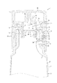
図1に示すように、本実施形態に係る二重容器1は、容器本体2と該容器本体2の口部3に装着される注出キャップ4とを備えている。また、容器本体2は、外気導入孔5を有する外層体6と該外層体6の内側に配置された内層体7とを備えている。内層体7は、内容物の注出に伴い減容変形しつつ外気導入孔5から外気を外層体6と内層体7との間に導入するようになっている。そして、注出キャップ4は、逆止弁8によって開閉可能な内容物の注出路Rを備えている。
As shown in FIG. 1, the double container 1 according to this embodiment includes a container
より具体的には、本例では、容器本体2は、口部3と、該口部3よりも拡径された胴部9と、胴部9の下部を閉塞する底部(図示省略)とからなるボトル状をなしている。また、容器本体2は、共押出し成形した二層構造のパリソンをブロー成形することで外層体6に対して内層体7を剥離可能に積層させた構成になっている。なお、容器本体2は、このような構成に代えて、外層体6と内層体7とを別々に形成した後に組み合わせることで構成してもよい。
More specifically, in this example, the
また、本例では、外気導入孔5は口部3に1つ形成されており、注出キャップ4に設けられた貫通孔10,11を通じて、外気を外気導入孔5まで導き外層体6と内層体7との間に導入するようになっている。口部3の外周面には、後述するリング部材29の環状壁30が嵌め込まれる環状溝34が形成されている。本例では、環状溝34内に外気導入孔5が配置されている。
In this example, one outside
注出キャップ4は、リング部材29を介して口部3に装着される装着筒12を備えている。また、注出キャップ4は、本例では、キャップ本体13、弁部材14及び内キャップ部材15からなっている。
The dispensing cap 4 includes a
キャップ本体13は、装着筒12と、該装着筒12の上端に連なる天壁16と、装着筒12にヒンジ17を介して連結された上蓋18とを備えている。天壁16には、注出筒19と、前述した貫通孔10とが設けられている。上蓋18には、注出筒19を閉塞するピン20が設けられている。
The
弁部材14は、筒壁21と、該筒壁21の内周側に連設された逆止弁8と、該筒壁21の外周側に連設された外気導入用逆止弁22とを備えている。逆止弁8は、本例では、円板状の弁体の外周縁を3本の弾性アームで筒壁21の内周面に連結した3点弁として構成されているが、その他の構成を採用することも可能である。また、外気導入用逆止弁22は、周方向に連続するフランジ状をなしている。筒壁21の上部は、キャップ本体13の天壁16から垂下する嵌合筒23に嵌合している。
The
内キャップ部材15は、キャップ本体13の天壁16と容器本体2の口部3との間に配置され、かつ、キャップ本体13の装着筒12の内周面にアンダーカットを介して嵌合される外筒24を備えている。また、外筒24の内周側には、底壁25が連設されている。底壁25の中央には開口26が形成されており、該開口26の周縁部によって逆止弁8の弁座が構成されている。また、該開口26の外周側には環状凹溝27が形成されており、該環状凹溝27には、弁部材14の筒壁21の下部が嵌合している。環状凹溝27の外周側には、口部3の上端内周面に嵌合する環状のシール突起28が垂設されている。外筒24の下部には、前述した貫通孔11が形成されている。
The
したがって、本例では、内容物の注出路Rは、キャップ本体13の注出筒19及び天壁16、弁部材14の筒壁21、並びに内キャップ部材15の底壁25及び開口26によって区画されている。
Therefore, in this example, the content extraction path R is defined by the
また、二重容器1は、容器本体2の口部3の外周面に装着されるリング部材29を備えている。リング部材29は、口部3の外周面に抜け出し不能に係止する環状壁30と、該環状壁30(本実施形態では環状壁30の上端縁)に折れ曲がり部31を介して外周側へ反転可能に連設された環状係止片32とを備えている。環状係止片32は、折れ曲がり部31を介して外周側へ反転させることで、注出キャップ4の装着筒12を係止するように構成されている。すなわち、装着筒12の内周面には環状突起33が形成されており、該環状突起33が、反転した環状係止片32の先端に係止するようになっている。なお、本例では環状突起33は周方向に連続して設けられているが、環状係止片32を係止できる限りでは周方向に断続して設けることも可能である。
Further, the double container 1 includes a
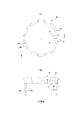
図2に示すように、環状係止片32は、本例では周方向に断続して設けられている。より具体的には、環状係止片32は、周方向に等間隔を空けて配置された複数(本例では8個)の係止片からなっている。なお、図2では、環状係止片32は反転前の成形時の状態で示されている。
As shown in FIG. 2, the
また、環状係止片32は、図1に示したように装着筒12が係止した状態で、注出キャップ4を口部3から引き抜こうとした場合に、この引き抜きを阻止する(容易な引き抜きを防止する)ものとなっている。この際に無理に引き抜きを行うと、折れ曲がり部31が破断するようになっている。折れ曲がり部31は、本例では、このような破断を生じ易くするための弱化部を有している。このような弱化部は、例えば、スリットや薄肉部によって構成することができる。本例では、折れ曲がり部31は、薄肉部からなる弱化部を有している。
Further, the
環状壁30は、本例では、平面視C字状をなしており(図2参照)、周方向両端部30a,30b間の間隔を広げるように弾性変形させつつ、口部3の環状溝34内に嵌め込めるようになっている。また、環状壁30は、本例では、口部3に設けられた外気導入孔5に挿入される気道確保用の挿入筒35を備えている。挿入筒35は、外層体6に形成された外気導入孔5の深さを超える長さを有し、外層体6と内層体7との間に外気導入用の気道を確保するようになっている。
In this example, the
なお、挿入筒35は、必ずしも設ける必要はなく、挿入筒35を設けない場合には、例えば、環状溝34及び環状壁30を、外気導入孔5を避けた位置及び範囲に配置すればよい。また、挿入筒35を設けない場合には、外気導入孔5は必ずしも口部3に設ける必要はなく、胴部9又は底部に設けるようにしてもよい。また、環状壁30は、本例では周方向に略360°の範囲に亘って延在するように設けたが、本願発明の目的を達成できる角度範囲であれば適宜変更することができる。但し、リング部材29の口部3に対する装着状態の安定性を考慮すると、周方向に180°以上の範囲に亘って設けることが好ましい。さらに、周方向に複数に分割したリング部材29とすることもできる。
Note that the
このように本実施形態に係る二重容器1は、容器本体2の口部3の外周面に装着されるリング部材29を備え、リング部材29は、口部3の外周面に抜け出し不能に係止する環状壁30と、該環状壁30に折れ曲がり部31を介して外周側へ反転可能に連設された環状係止片32とを備え、注出キャップ4は、反転した環状係止片32の先端に係止する装着筒12を備え、環状係止片32は、装着筒12が係止した状態で注出キャップ4が口部3から引き抜かれると、折れ曲がり部31が破断するようになっている。
As described above, the double container 1 according to the present embodiment includes the
したがって、本実施形態に係る二重容器1によれば、リング部材29の環状壁30を容器本体2の口部3の外周面に抜け出し不能に係止すると共に、リング部材29の反転した環状係止片32の先端に注出キャップ4の装着筒12を係止することができるので、リング部材29を介して注出キャップ4を口部3に装着することができる。また、本実施形態に係る二重容器1によれば、このように装着筒12が係止した状態で注出キャップ4が口部3から引き抜かれた場合には、環状係止片32の折れ曲がり部31が破断し、注出キャップ4を再び口部3に装着することができなくなるため、たとえ内容物を再充填したとしても容器を使用することができない。したがって、本実施形態に係る二重容器1によれば、内容物の再充填を伴う使用を防止することができる。
Therefore, according to the double container 1 according to the present embodiment, the
また、本実施形態では、環状係止片32は周方向に断続して設けられているので、注出キャップ4が口部3から引き抜かれた場合の折れ曲がり部31の破断をより確実に生じさせることができる。
Moreover, in this embodiment, since the
また、本実施形態では、折れ曲がり部31は破断を生じ易くするための弱化部を有しているので、注出キャップ4が口部3から引き抜かれた場合の折れ曲がり部31の破断をより一層確実に生じさせることができる。
Moreover, in this embodiment, since the bending
また、本実施形態では、リング部材29の環状壁30は平面視C字状をなしているので、リング部材29の環状壁30を、容器本体2の口部3に容易に装着することができる。
In the present embodiment, the
さらに、本実施形態では、外層体7の外気導入孔5は口部3に設けられており、リング部材29の環状壁30は外気導入孔5に挿入される気道確保用の挿入筒35を備えているので、外気導入孔5を通じたよりスムーズな外気の導入を可能にすることができる。
Furthermore, in the present embodiment, the outside
次に、図3〜図4を参照して、本発明の他の実施形態に係る二重容器1’について詳細に例示説明する。
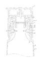
本実施形態に係る二重容器1’は、容器本体2の口部3に2つの外気導入孔5を設けた点、及びリング部材29’の形態が異なる点を除いては、前述した実施形態の場合と同一の構成になっている。
Next, with reference to FIGS. 3 to 4, a double container 1 ′ according to another embodiment of the present invention will be described in detail as an example.
The double container 1 ′ according to the present embodiment is the same as that of the above-described embodiment except that the
ここに、本実施形態のリング部材29’は、特に、環状壁30が周方向に伸縮自在な伸縮部36(図2参照)を備えている点で、前述した実施形態の場合と異なっている。以下、リング部材29’についてより具体的に説明する。
Here, the
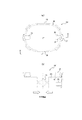
リング部材29’は、前述した実施形態の場合と同様に、口部3の外周面に抜け出し不能に係止する環状壁30と、該環状壁30(本実施形態では環状壁30の上端縁)に折れ曲がり部31を介して外周側へ反転可能に連設された環状係止片32とを備えている。環状係止片32は、本例では、図4に示すように、周方向に間隔を空けて配置された複数(本例では6個)の係止片からなっている。
As in the case of the above-described embodiment, the
環状壁30は、本例では、周方向に伸縮自在な伸縮部36を備えており、伸縮部36の伸縮によって口部3の環状溝34内への嵌め込みを容易に行えるようになっている。伸縮部36は、本例では、環状壁30の軸線を挟んで対向する一対の折り畳み可能部として構成されている。
In this example, the
また、環状壁30には、一対の折り畳み可能部(伸縮部36)の折り畳み方向に沿って対向する一対の気道確保用の挿入筒35を備えている。一対の挿入筒35は、それぞれ、口部3に設けられた外気導入孔5に挿入されて、外層体6と内層体7との間に外気導入用の気道を確保するようになっている。なお、一対の挿入筒35は必ずしも設ける必要がないことは、前述した実施例の場合と同様である。
In addition, the
かかる構成になる本実施形態に係る二重容器1’によれば、前述した実施形態の場合と同様の効果を得ることができる。また、本実施形態では、リング部材29’の環状壁30が周方向に伸縮自在な伸縮部36を備えているので、口部3の環状溝34内への環状壁30の嵌め込みを伸縮部36の伸縮によって容易に行うことが可能となる。
According to the double container 1 ′ according to the present embodiment having such a configuration, the same effects as those of the above-described embodiment can be obtained. Further, in the present embodiment, the
前述したところは本発明の一実施形態を示したにすぎず、特許請求の範囲において、種々の変更を加えてもよいことは言うまでもない。 The above description shows only one embodiment of the present invention, and it goes without saying that various modifications may be made within the scope of the claims.
1,1’ 二重容器
2 容器本体
3 口部
4 注出キャップ
5 外気導入孔
6 外層体
7 内層体
8 逆止弁
9 胴部
10 貫通孔
11 貫通孔
12 装着筒
13 キャップ本体
14 弁部材
15 内キャップ部材
16 天壁
17 ヒンジ
18 上蓋
19 注出筒
20 ピン
21 筒壁
22 外気導入用逆止弁
23 嵌合筒
24 外筒
25 底壁
26 開口
27 環状凹溝
28 シール突起
29,29’ リング部材
30 環状壁
30a,30b 周方向両端部
31 折れ曲がり部
32 環状係止片
33 環状突起
34 環状溝
35 挿入筒
36 伸縮部
R 注出路
DESCRIPTION OF SYMBOLS 1,1 '
Claims (6)
前記容器本体は、外気導入孔を有する外層体と該外層体の内側に配置された内層体とを備え、
前記内層体は、内容物の注出に伴い減容変形しつつ前記外気導入孔から外気を前記外層体と前記内層体との間に導入し、
前記注出キャップは、逆止弁によって開閉可能な前記内容物の注出路を備える二重容器において、
前記容器本体の前記口部の外周面に装着されるリング部材を備え、
前記リング部材は、前記口部の外周面に抜け出し不能に係止する環状壁と、該環状壁に折れ曲がり部を介して外周側へ反転可能に連設された環状係止片とを備え、
前記注出キャップは、反転した前記環状係止片の先端に係止する装着筒を備え、
前記環状係止片は、前記装着筒が係止した状態で前記注出キャップが前記口部から引き抜かれると、前記折れ曲がり部が破断するようになっていることを特徴とする二重容器。 A container body and a dispensing cap attached to the mouth of the container body;
The container body includes an outer layer body having an outside air introduction hole and an inner layer body arranged inside the outer layer body,
The inner layer body introduces outside air between the outer layer body and the inner layer body through the outside air introduction hole while volume-reducing and deforming as the contents are poured out,
The pouring cap is a double container having a pouring path for the contents that can be opened and closed by a check valve.
A ring member mounted on the outer peripheral surface of the mouth of the container body;
The ring member includes an annular wall that is locked on the outer peripheral surface of the mouth so as not to be pulled out, and an annular locking piece that is connected to the annular wall so as to be able to be reversed to the outer peripheral side via a bent portion.
The dispensing cap includes a mounting cylinder that is locked to the tip of the inverted annular locking piece,
2. The double container according to claim 1, wherein the bent portion is configured to be broken when the pouring cap is pulled out from the mouth portion in a state where the mounting cylinder is locked.
前記リング部材の前記環状壁は、前記外気導入孔に挿入される気道確保用の挿入筒を備える、請求項1〜5のいずれか一項に記載の二重容器。 The outside air introduction hole of the outer layer body is provided in the mouth,
The said annular wall of the said ring member is a double container as described in any one of Claims 1-5 provided with the insertion cylinder for airway ensuring inserted in the said external air introduction hole.
Priority Applications (1)
| Application Number | Priority Date | Filing Date | Title |
|---|---|---|---|
| JP2015017119A JP6324329B2 (en) | 2015-01-30 | 2015-01-30 | Double container |
Applications Claiming Priority (1)
| Application Number | Priority Date | Filing Date | Title |
|---|---|---|---|
| JP2015017119A JP6324329B2 (en) | 2015-01-30 | 2015-01-30 | Double container |
Publications (2)
| Publication Number | Publication Date |
|---|---|
| JP2016141413A JP2016141413A (en) | 2016-08-08 |
| JP6324329B2 true JP6324329B2 (en) | 2018-05-16 |
Family
ID=56569553
Family Applications (1)
| Application Number | Title | Priority Date | Filing Date |
|---|---|---|---|
| JP2015017119A Active JP6324329B2 (en) | 2015-01-30 | 2015-01-30 | Double container |
Country Status (1)
| Country | Link |
|---|---|
| JP (1) | JP6324329B2 (en) |
Cited By (1)
| Publication number | Priority date | Publication date | Assignee | Title |
|---|---|---|---|---|
| JP2650382B2 (en) | 1988-12-20 | 1997-09-03 | 松下電器産業株式会社 | Digital signal processing method and circuit |
Family Cites Families (3)
| Publication number | Priority date | Publication date | Assignee | Title |
|---|---|---|---|---|
| JPS52165856U (en) * | 1976-06-08 | 1977-12-15 | ||
| JP4803650B2 (en) * | 2005-11-04 | 2011-10-26 | 日本クラウンコルク株式会社 | Refill prevention cap |
| JP5992242B2 (en) * | 2012-07-31 | 2016-09-14 | 株式会社吉野工業所 | Dispensing cap and container having the same |
-
2015
- 2015-01-30 JP JP2015017119A patent/JP6324329B2/en active Active
Cited By (1)
| Publication number | Priority date | Publication date | Assignee | Title |
|---|---|---|---|---|
| JP2650382B2 (en) | 1988-12-20 | 1997-09-03 | 松下電器産業株式会社 | Digital signal processing method and circuit |
Also Published As
| Publication number | Publication date |
|---|---|
| JP2016141413A (en) | 2016-08-08 |
Similar Documents
| Publication | Publication Date | Title |
|---|---|---|
| JP6366517B2 (en) | Double container | |
| JP6594771B2 (en) | Double container | |
| JP6730095B2 (en) | Double container | |
| ES2948796T3 (en) | Safety lock | |
| MX2021011789A (en) | Container closure. | |
| JP6324329B2 (en) | Double container | |
| WO2018198533A1 (en) | Delamination container | |
| JP5992221B2 (en) | Hinge cap | |
| JP6027944B2 (en) | Refill container | |
| JP4618579B2 (en) | Double container and molding method | |
| ES2670496T3 (en) | Tamper Proof Closure | |
| JP6474644B2 (en) | Double container | |
| RU2017103945A (en) | A CONTAINER HAVING A HEAD OF A CONTAINER THAT IS FILLED OR MAY BE FILLED WITH SUBSTANCE | |
| JP2005313982A (en) | Thin container | |
| JP2010260588A (en) | Refilling container | |
| JP6194573B2 (en) | Outlet stopper and packaging container | |
| JP6220689B2 (en) | Resin cap and its manufacturing method | |
| ITMI970232U1 (en) | BOTTLE WITH SEAT TO WELCOME THE UNCAPPED TURACCIOLO | |
| US708264A (en) | Bottle-stopper. | |
| JP2015105124A (en) | Plastic plastic blow container | |
| JP6508952B2 (en) | Hinge cap | |
| JP7403294B2 (en) | extrusion blow container | |
| JP2015145258A (en) | Pouring vessel with shift plug | |
| JP5637591B2 (en) | Blow molding container | |
| ES2247879B2 (en) | MEANS OF RETAINING THE LANDSCAPE OF AN IRRELLENABLE LID. |
Legal Events
| Date | Code | Title | Description |
|---|---|---|---|
| A621 | Written request for application examination |
Free format text: JAPANESE INTERMEDIATE CODE: A621 Effective date: 20170728 |
|
| A977 | Report on retrieval |
Free format text: JAPANESE INTERMEDIATE CODE: A971007 Effective date: 20180405 |
|
| TRDD | Decision of grant or rejection written | ||
| A01 | Written decision to grant a patent or to grant a registration (utility model) |
Free format text: JAPANESE INTERMEDIATE CODE: A01 Effective date: 20180410 |
|
| A61 | First payment of annual fees (during grant procedure) |
Free format text: JAPANESE INTERMEDIATE CODE: A61 Effective date: 20180410 |
|
| R150 | Certificate of patent or registration of utility model |
Ref document number: 6324329 Country of ref document: JP Free format text: JAPANESE INTERMEDIATE CODE: R150 |