JP6322023B2 - Measuring device and failure diagnosis device using the same - Google Patents
Measuring device and failure diagnosis device using the same Download PDFInfo
- Publication number
- JP6322023B2 JP6322023B2 JP2014069709A JP2014069709A JP6322023B2 JP 6322023 B2 JP6322023 B2 JP 6322023B2 JP 2014069709 A JP2014069709 A JP 2014069709A JP 2014069709 A JP2014069709 A JP 2014069709A JP 6322023 B2 JP6322023 B2 JP 6322023B2
- Authority
- JP
- Japan
- Prior art keywords
- yaw rate
- physical quantity
- lane
- calibration
- error
- Prior art date
- Legal status (The legal status is an assumption and is not a legal conclusion. Google has not performed a legal analysis and makes no representation as to the accuracy of the status listed.)
- Active
Links
- 238000003745 diagnosis Methods 0.000 title claims description 11
- 238000000034 method Methods 0.000 claims description 33
- 238000004364 calculation method Methods 0.000 claims description 30
- 238000012417 linear regression Methods 0.000 claims description 19
- 238000005259 measurement Methods 0.000 claims description 13
- 230000008569 process Effects 0.000 description 20
- 238000001514 detection method Methods 0.000 description 6
- 230000006870 function Effects 0.000 description 6
- 230000007935 neutral effect Effects 0.000 description 6
- 230000001133 acceleration Effects 0.000 description 5
- 230000002265 prevention Effects 0.000 description 4
- 238000010586 diagram Methods 0.000 description 3
- 238000004088 simulation Methods 0.000 description 3
- 230000007246 mechanism Effects 0.000 description 2
- 238000005070 sampling Methods 0.000 description 2
- 230000005540 biological transmission Effects 0.000 description 1
- 230000008859 change Effects 0.000 description 1
- 238000006243 chemical reaction Methods 0.000 description 1
- 230000004069 differentiation Effects 0.000 description 1
- 239000006185 dispersion Substances 0.000 description 1
- 230000001360 synchronised effect Effects 0.000 description 1
Images


Description
本発明は、物理量を直接計測する物理量計測手段と、この物理量を推定する物理量推定手段とを有し、物理量計測手段で計測した第1物理量と物理量推定手段で推定した第2物理量とに基づいて第1物理量を較正した較正物理量を求める計測装置、及びそれを用いた故障診断装置に関する。 The present invention has a physical quantity measuring means for directly measuring a physical quantity and a physical quantity estimating means for estimating the physical quantity, and is based on the first physical quantity measured by the physical quantity measuring means and the second physical quantity estimated by the physical quantity estimating means. The present invention relates to a measuring device for obtaining a calibrated physical quantity obtained by calibrating a first physical quantity, and a failure diagnosis apparatus using the measuring device.
従来、車両に搭載されているヨーレートセンサ等の計測装置から出力される計測値は、熱害等の影響を受けて誤差が生じやすく、そのため、出力される計測値を中立較正(ゼロ点較正)する技術が種々提案されている。例えば、特許文献1(特許第5314649号公報)には、基準となる計測装置で計測した値と、この計測装置とは別の計測装置で計測した値とを比較し、移動平均により定常的にずれている成分をオフセット成分として中立較正する技術が開示されている。 Conventionally, measurement values output from a measurement device such as a yaw rate sensor mounted on a vehicle are likely to cause errors due to the influence of heat damage, etc. Therefore, the output measurement values are neutrally calibrated (zero point calibration). Various techniques have been proposed. For example, in Patent Document 1 (Japanese Patent No. 5314649), a value measured by a reference measurement device is compared with a value measured by a measurement device different from the measurement device, and is constantly measured by moving average. A technique for performing neutral calibration using offset components as offset components is disclosed.
又、例えば特許文献2(特開2011−169728号公報)には、ヨーレートセンサの中立較正を行うに際し、カメラで撮影した画像に基づいて認識した車線からヨーレートを推定し、この推定値に基づいてヨーレートを較正する技術が開示されている。 Further, for example, in Patent Document 2 (Japanese Patent Application Laid-Open No. 2011-169728), when performing neutral calibration of the yaw rate sensor, the yaw rate is estimated from the lane recognized based on the image captured by the camera, and based on this estimated value. A technique for calibrating the yaw rate is disclosed.
更に、特許文献3(特許第3637801号公報)や特許文献4(特許第4432885号公報)には、操舵角センサで検出した操舵角信号に基づいてヨーレートを推定し、この推定したヨーレートに基づいてヨーレートセンサの故障検出を行う技術が開示されている。 Furthermore, in Patent Document 3 (Japanese Patent No. 3637801) and Patent Document 4 (Japanese Patent No. 4432885), a yaw rate is estimated based on a steering angle signal detected by a steering angle sensor, and based on this estimated yaw rate. A technique for detecting a failure of a yaw rate sensor is disclosed.
ところで、路面横断勾配(カント)を有する走行路や横風を受けた状態での走行で直進走行しようとする場合、運転者はハンドルを切った状態で走行させる。このような状況で、特許文献1に開示されているように、操舵角に基づいてヨーレートセンサの中立較正を行った場合、上述した路面横断勾配や横風が横力外乱として作用するため誤差が大きくなり、ヨーレートセンサ等の計測装置の中立較正精度が低下してしまう不都合がある。
By the way, when the vehicle is going to travel straight in a state where a crossing slope (cant) has a crossing slope (cant) or in a state of receiving a crosswind, the driver travels with the steering wheel turned off. In such a situation, as disclosed in
又、操舵角から推定されるヨーレートは実際の車両ヨーレートに対して位相特性が異なるため、位相特性の誤差分を除外するため定常状態に限定する方策や、位相合わせ処理を行う方策が必要となる。この場合、補正頻度が低下したり、位相合わせ自体の誤差により精度良い推定・補正が困難となる。 In addition, since the yaw rate estimated from the steering angle has a phase characteristic different from that of the actual vehicle yaw rate, it is necessary to take measures to limit to a steady state or to perform a phase matching process in order to exclude the phase characteristic error. . In this case, the correction frequency is reduced, and accurate estimation / correction becomes difficult due to errors in the phase alignment itself.
この点、特許文献2に開示されているように、カメラで撮影した画像に基づいて車線を検出し、検出した車線に基づいてヨーレートを推定する技術では、路面横断勾配や横風の影響を受け難く、引用文献1に開示されている技術に比し、中立較正を精度良く行うことができる。しかし、画像処理等の遅延により、特許文献1に記載の手段同様、両者の位相特性の差異による誤差分が含まれてしまうという不都合がある。
In this regard, as disclosed in
又、、ヨーレートセンサ等のレートジャイロを用いた計測装置には、誤差要因としてオフセット誤差以外にスケールファクタ誤差がある。特許文献2に開示されている技術では、オフセット誤差にスケールファクタ誤差因子が含まれた状態で検出されているため、スケールファクタ誤差をオフセット誤差として見積もってしまったり、又、その逆が生じることによって誤差の推定及び較正精度を高めることができない不都合がある。
In addition, a measurement apparatus using a rate gyro such as a yaw rate sensor has a scale factor error as an error factor in addition to an offset error. In the technique disclosed in
又、特許文献3,4に開示されているように、計測装置の故障診断として、操舵角センサを用いた場合、上述したように路面横断勾配や横風の影響を受け易く、故障診断を精度良く行うことができない不具合がある。
Further, as disclosed in
本発明は、上記事情に鑑み、オフセット誤差とスケールファクタ誤差とを個別に検出することができ、なおかつ位相特性の影響を受け難く、更に、スケールファクタ誤差及びオフセット誤差の較正を高精度に行うことのできる計測装置、及びそれを用いた故障診断装置を提供することを目的とする。 In view of the above circumstances, the present invention can individually detect an offset error and a scale factor error, is not easily affected by the phase characteristics, and performs calibration of the scale factor error and the offset error with high accuracy. An object of the present invention is to provide a measuring device capable of performing the above and a failure diagnosis device using the same.
本発明による計測装置は、第1物理量を計測する物理量計測手段と、前記第1物理量を推定する第2物理量を設定する、前記物理量計測手段とは別の物理量推定手段と、前記第1物理量と前記第2物理量とを座標軸として座標データを取得する座標データ取得手段と、取得した前記座標データに基づき最小二乗法により線形回帰パラメータを求めるパラメータ演算手段と、前記線形回帰パラメータの傾きと切片とをスケールファクタ誤差とオフセット誤差として同定するパラメータ同定手段と、前記スケールファクタ誤差と前記オフセット誤差とに基づいて前記物理量計測手段で計測した前記第1物理量を較正して較正物理量を求める物理量較正手段とを備える計測装置において、走行車線を規定する車線区画線を検出する車線区画線演算手段と、前記車線区画線演算手段で検出した前記車線区画線に基づいて該車線区画線の曲率及び車両と該車線区画線とのなす角度を求める対車線ヨー角演算手段とを更に有し、前記物理量計測手段が前記第1物理量である前記車両のヨーレートを検出するヨーレートセンサであり、前記物理量推定手段が前記対車線ヨー角演算手段で求めた前記曲率及び前記車両と前記車線区画線とのなす角から前記第2物理量である該車両の推定ヨーレートを求める推定ヨーレート演算部であり、前記座標データ取得手段は、前記ヨーレートセンサにて検出した前記ヨーレートと前記推定ヨーレート演算部で求めた前記推定ヨーレートとを座標軸として前記座標データを取得する。 The measuring apparatus according to the present invention includes a physical quantity measuring unit that measures a first physical quantity, a physical quantity estimating unit that sets a second physical quantity that estimates the first physical quantity, and that is different from the physical quantity measuring unit, and the first physical quantity Coordinate data acquisition means for acquiring coordinate data using the second physical quantity as a coordinate axis, parameter calculation means for obtaining a linear regression parameter by the least square method based on the acquired coordinate data, and the slope and intercept of the linear regression parameter Parameter identifying means for identifying as a scale factor error and an offset error; and a physical quantity calibration means for calibrating the first physical quantity measured by the physical quantity measuring means based on the scale factor error and the offset error to obtain a calibration physical quantity. in includes Ru measuring device, lane marking operations manual for detecting a lane line defining the driving lane And an anti-lane yaw angle calculation means for obtaining a curvature of the lane marking and an angle formed by the vehicle and the lane marking based on the lane marking detected by the lane marking calculation means, The physical quantity measuring means is a yaw rate sensor that detects the yaw rate of the vehicle that is the first physical quantity, and the physical quantity estimating means forms the curvature obtained by the anti-lane yaw angle calculating means and the vehicle and the lane line. An estimated yaw rate calculation unit that obtains an estimated yaw rate of the vehicle that is the second physical quantity from a corner, wherein the coordinate data acquisition unit detects the yaw rate detected by the yaw rate sensor and the estimated yaw rate calculated by the estimated yaw rate calculation unit. The coordinate data is acquired using and as coordinate axes .
本発明による前記計測装置を用いた故障診断装置は、前記スケールファクタ誤差及び前記オフセット誤差を予め設定した故障判定用しきい値と比較し、少なくとも一方の誤差が該故障判定用しきい値を越えている場合、前記物理量計測手段の故障と判定する故障診断手段を備える。 The failure diagnosis device using the measuring device according to the present invention compares the scale factor error and the offset error with a preset failure determination threshold, and at least one of the errors exceeds the failure determination threshold. If there is, a failure diagnosis means for determining that the physical quantity measurement means is faulty is provided.
本発明によれば、第1物理量と、これを推定する第2物理量とを異なる装置で求め、得られた各物理量を座標軸として取得した座標データに基づき最小二乗法により線形回帰パラメータを求め、この線形回帰パラメータの傾きと切片とをスケールファクタ誤差とオフセット誤差として同定して、第1物理量を較正するようにしたので、較正により得られた物理量は、オフセット誤差とスケールファクタ誤差とで個別に較正されているため、位相特性の影響を受け難く、スケールファクタ誤差及びオフセット誤差の較正を高精度に行うことができる。 According to the present invention, the first physical quantity and the second physical quantity for estimating the first physical quantity are obtained by different devices, and the linear regression parameters are obtained by the least square method based on the coordinate data obtained using the obtained physical quantities as coordinate axes. Since the slope and intercept of the linear regression parameter are identified as the scale factor error and the offset error and the first physical quantity is calibrated, the physical quantity obtained by the calibration is separately calibrated by the offset error and the scale factor error. Therefore, the scale factor error and the offset error can be calibrated with high accuracy without being affected by the phase characteristics.
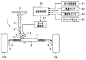
以下、図面に基づいて本発明の一実施形態を説明する。図1の符号1は操舵角を運転者入力と独立して設定自在な電動パワーステアリング装置である。この電動パワーステアリング装置1は、ステアリング軸2が、図示しない車体フレームにステアリングコラム3を介して回動自在に支持されており、その一端が運転席側へ延出され、他端がエンジンルーム側へ延出されている。ステアリング軸2の運転席側端部には、ステアリングホイール4が固設され、又、エンジンルーム側へ延出する端部には、ピニオン軸5が連設されている。
Hereinafter, an embodiment of the present invention will be described with reference to the drawings.
エンジンルームには、車幅方向へ延出するステアリングギヤボックス6が配設されており、このステアリングギヤボックス6にラック軸7が往復移動自在に挿通支持されている。このラック軸7に形成されたラック(図示せず)に、ピニオン軸5に形成されたピニオンが噛合されて、ラックアンドピニオン式のステアリングギヤ機構が形成されている。
A
又、ラック軸7の左右両端はステアリングギヤボックス6の端部から各々突出されており、その端部に、タイロッド8を介してフロントナックル9が連設されている。このフロントナックル9は、操舵輪としての左右輪10L,10Rを回動自在に支持すると共に、車体フレームに転舵自在に支持されている。従って、ステアリングホイール4を操作し、ステアリング軸2、ピニオン軸5を回転させると、このピニオン軸5の回転によりラック軸7が左右方向へ移動し、その移動によりフロントナックル9がキングピン軸(図示せず)を中心に回動して、左右輪10L,10Rが左右方向へ転舵される。
The left and right ends of the rack shaft 7 protrude from the end of the
又、ピニオン軸5にアシスト伝達機構11を介して、電動パワーステアリングモータ(電動モータ)12が連設されており、この電動モータ12にてステアリングホイール4に加える操舵トルクのアシスト、及び、設定されたヨーレート(目標ヨーレート)となるような目標ヨーモーメント(操舵トルク)の付加が行われる。電動モータ12はモータ駆動部21から出力される駆動力で駆動される。このモータ駆動部21には、後述する操舵制御部20から目標操舵トルクに対応する制御信号が入力される。
An electric power steering motor (electric motor) 12 is connected to the pinion shaft 5 via an assist transmission mechanism 11, and assists and sets steering torque applied to the
この操舵制御部20の入力側には、走行車線を規制する左右の白線を代表とする車線区画線を検出し、これら車線区画線の位置情報を取得する前方認識手段及び車線区画線演算手段としての前方認識装置31、車速Vを検出する車速センサ32、操舵角を検出する操舵角センサ33、第1物理量であるヨーレートγを検出する物理量計測手段としてのヨーレートセンサ34等が接続されており、これらのパラメータに基づき、運転者の操舵力を補助する電動パワーステアリング制御、車両を目標進行路に沿って走行させるレーンキープ制御、走行車線からの車線逸脱を防止する車線逸脱防止制御等を実行する。以下においては、この各制御のうち車線逸脱防止制御機能について説明する。
On the input side of the
前方認識装置31は、例えば、車室内の天井前方に一定の間隔をもって取り付けられ、車外の対象を異なる視点からステレオ撮像するメインカメラとサブカメラとからなるステレオカメラと、この両カメラからの画像データを処理するステレオ画像処理部とで構成されている。
The
又、この前方認識装置31のステレオ画像処理装置における、各カメラからの画像データの処理は、例えば以下のように行われる。先ず、メインカメラで撮影した基準画像とサブカメラで撮影した比較画像との視差から距離情報を求め、距離画像を生成する。走行車線の左右を規制する車線区画線は道路面と比較して高輝度であるという知得に基づき、道路の幅方向の輝度変化を評価して、画像平面における左右の車線区画線の位置を画像平面上で特定する。
Further, the processing of image data from each camera in the stereo image processing device of the
この車線区画線の仮装平面上の二軸座標(x,z)は、画像平面上の位置(i,j)とこの位置に関して算出された距離情報に基づいて、周知の座標変換式より算出される。自車両の位置を基準に設定された実空間の座標系は、本実施形態では、例えば、図5に示すように、ステレオカメラの中央真下の道路面を原点として、車幅方向をX軸(左方向を「+」)、車長方向(距離方向)をZ軸(前方向を「+」)とする。このとき、X−Z平面は、道路が平坦な場合、道路面と一致する。 The biaxial coordinates (x, z) of the lane marking on the virtual plane are calculated by a known coordinate conversion formula based on the position (i, j) on the image plane and the distance information calculated with respect to this position. The In the present embodiment, for example, as shown in FIG. 5, the coordinate system of the real space set based on the position of the host vehicle is based on the road surface directly below the center of the stereo camera, and the vehicle width direction is the X axis ( The left direction is “+”) and the vehicle length direction (distance direction) is the Z-axis (front direction is “+”). At this time, the XZ plane coincides with the road surface when the road is flat.
道路モデルは、道路上の自車両の走行車線を距離方向に複数区間に分割し、各区間における左右の車線区画線を所定に近似して連結することによって表現される。尚、本実施形態では、走行車線の形状を1組のカメラからの画像を基に認識する例で説明したが、他に、単眼カメラ、カラーカメラからの画像情報を基に求めるものであっても良い。又、車線区画線までの距離が認識できるものであれば、前方認識装置31は、ミリ波レーダや赤外線レーザレーダであっても良い。
The road model is expressed by dividing the traveling lane of the host vehicle on the road into a plurality of sections in the distance direction, and connecting the left and right lane markings in each section to a predetermined approximation. In the present embodiment, the example of recognizing the shape of the driving lane based on images from a set of cameras has been described. However, the shape is obtained based on image information from a monocular camera and a color camera. Also good. Further, as long as the distance to the lane marking can be recognized, the
次に、操舵制御部20で実行される車線逸脱防止制御について説明する。図2に示すように、操舵制御部20には車線逸脱防止制御を実行する機能として、目標ヨーレート演算部41、フィードフォワード制御値演算部42、物理量推定手段としての推定ヨーレート演算部43、物理量較正手段としての較正ヨーレート演算部44、フィードバック制御値演算部45、レートリミッタ演算部46、操舵トルク演算部47を備えている。
Next, the lane departure prevention control executed by the
目標ヨーレート演算部41は、目標ヨーレートγ*を以下のようにして求める。尚、本発明の対車線ヨー角演算手段は、この目標ヨーレート演算部41に含まれている。
The target yaw
すなわち、図5に示すように、基準画像データと比較画像データとに基づいて生成した仮想道路平面上に、距離データに基づいて算出した左右車線区画線の候補点PL,PRをプロットする。この仮想道路平面には自車両Mが配設されており、自車両Mに搭載されている前方認識装置(ステレオカメラ)31の中央の真下の道路面上の点を原点とし、自車両Mの車幅方向にx軸、前後方向にz軸を取る座標が設定される。尚、符号θyawは走行車線と自車両Mとのなす角(対車線ヨー角)である。 That is, as shown in FIG. 5, the left and right lane line candidate points PL and PR calculated based on the distance data are plotted on the virtual road plane generated based on the reference image data and the comparison image data. The host vehicle M is disposed on the virtual road plane, and a point on the road surface immediately below the center of the front recognition device (stereo camera) 31 mounted on the host vehicle M is used as an origin, and the host vehicle M Coordinates that take the x-axis in the vehicle width direction and the z-axis in the front-rear direction are set. The symbol θyaw is an angle formed by the traveling lane and the host vehicle M (to-lane yaw angle).
そして、この左右にプロットした候補点PL,PRの群から最小二乗法により、左右車線区画線の二次モデル式
Y_LINE_L=A_L・Z2+B_L・Z+C_L…(1)
Y_LINE_R=A_R・Z2+B_R・Z+C_R…(2)
の各係数A_L,B_L,C_L,A_R,B_R,C_Rを求め、これにより左右の車線区画線モデルを求める。尚、ここで、A_L、A_Rは車線曲率に関するパラメータであり、左側車線区画線の曲率κは、κ=2・A_L、右側の車線区画線の曲率κは、κ=2・A_Rである。又、B_L,B_Rは自車両Mの中央を通る仮想線に対する自車両Mの傾き(ヨー角)に関する角度パラメータである。更に、C_L,C_Rは左右車線区画線からの横位置を示す係数である。
Then, the candidate points are plotted in the left-right PL, by the least square method from the group of PR, the left and right lane line quadratic model formula Y_LINE_L = A_L · Z 2 + B_L · Z + C_L ... (1)
Y_LINE_R = A_R · Z 2 + B_R · Z + C_R (2)
The coefficients A_L, B_L, C_L, A_R, B_R, and C_R are obtained, thereby obtaining the left and right lane marking models. Here, A_L and A_R are parameters relating to the lane curvature, the curvature κ of the left lane marking is κ = 2 · A_L, and the curvature κ of the right lane marking is κ = 2 · A_R. B_L and B_R are angle parameters related to the inclination (yaw angle) of the host vehicle M with respect to a virtual line passing through the center of the host vehicle M. Further, C_L and C_R are coefficients indicating the lateral position from the left and right lane markings.
そして、自車両Mの対車線ヨー角θyawを、
θyaw=(B_L+B_R)/2…(3)
から求める。
And the anti-lane yaw angle θyaw of the host vehicle M is
θyaw = (B_L + B_R) / 2 (3)
Ask from.
又、走行車線の中央からの自車両位置である車線幅方向車両横位置Yを、
Y=(C_L+C_R)/2…(4)
から求める。
Also, the vehicle lateral position Y in the lane width direction, which is the vehicle position from the center of the traveling lane,
Y = (C_L + C_R) / 2 (4)
Ask from.
次いで、車線区画線_車両間距離Lを、
L=((C_L−C_R)−TR)/2−Y…(5)
から算出する。ここで、TRは車両のトレッドであり、本実施形態では、タイヤの外側端位置を車線逸脱判定の基準に用いるものとする。
Next, the lane line _inter-vehicle distance L
L = ((C_L-C_R) -TR) / 2-Y (5)
Calculate from Here, TR is a tread of the vehicle, and in the present embodiment, the outer end position of the tire is used as a reference for the lane departure determination.
そして、走行車線から逸脱する車線逸脱予想時間Tttlcを、例えば、
Tttlc=L/(V・sin(θyaw))…(6)
から求める。
Then, the estimated lane departure time Tttlc deviating from the driving lane is, for example,
Tttlc = L / (V · sin (θyaw)) (6)
Ask from.
そして、対車線ヨー角θyawと車線逸脱予想時間Tttlcとに基づき、車線逸脱を防止する目標ヨーレートγ*を、
γ*=−θyaw/Tttlc…(7)
から求める。
Based on the anti-lane yaw angle θyaw and the estimated lane departure time Tttlc, the target yaw rate γ * for preventing the lane departure is
γ * = − θyaw / Tttlc (7)
Ask from.
そして、フィードフォワード制御値演算部42は、目標ヨーレートγ*を所定ゲインで補正してフィードフォワード値Mzffを設定する。
Then, the feedforward control
一方、推定ヨーレート演算部43は、前方認識装置31で認識した画像に基づいて求めた車線区画線の車線曲率κと対車線ヨー角θyaw、及び車速センサ32で検出した車速Vに基づいて、第2物理量である推定ヨーレートγlaneを、
γlane=κ・V+dθyaw/dt…(8)
から求める。
On the other hand, the estimated yaw
γlane = κ · V + dθyaw / dt (8)
Ask from.
この推定ヨーレートγlaneは、前方認識装置31で認識した画像に基づいて求めているため、路面横断勾配(カント)や横風の影響を受けることなく高い精度でヨーレートを推定することができる。すなわち、図6に示すように、自車両Mが路面横断勾配を有する直進路を走行する場合、車体に対して下り方向の横力Fyが作用するため、運転者はハンドルを上り方向に切った状態で直進走行する。従って、ヨーレートをハンドル角に基づいて推定した場合、この横力Fyが外乱として作用するため、ヨーレートを高い精度で推定することができない。
Since the estimated yaw rate γlane is obtained based on the image recognized by the
これに対し、本実施形態では、前方認識装置31で認識した画像から求めた左右の車線区画線の曲線近似式に基づいて、推定ヨーレートγlaneを求めているため、自車両Mに横力Fyが作用しても、これが車線区画線を求める際に外乱として作用することがないので、推定ヨーレートγlaneを高い精度で求めることができる。
On the other hand, in this embodiment, since the estimated yaw rate γlane is obtained based on the curve approximation formula of the left and right lane markings obtained from the image recognized by the
そして、較正ヨーレート演算部44は、推定ヨーレートγlaneとヨーレートセンサ34で検出したヨーレートγとの関係から、ヨーレートγを較正した較正ヨーレートγcalを求める。この較正ヨーレート演算部44での処理は、具体的には、図3に示す較正ヨーレート演算ルーチンに従って実行される。
Then, the calibration yaw
このルーチンでは、先ず、ステップS1で、推定ヨーレートγlaneを時間微分することで、推定ヨー角加速度dγlane/dtを求める。 In this routine, first, in step S1, an estimated yaw angular acceleration dγlane / dt is obtained by time differentiation of the estimated yaw rate γlane.
次いで、ステップS2へ進み、推定ヨー角加速度dγlane/dtが予め設定したしきい値γsl以上か否かを調べる。この推定ヨー角加速度dγlane/dtは、後述する最小二乗を行うためのサンプルデータであり、しきい値γslは、推定ヨー角加速度dγlane/dtの変動が小さいものを排除し、サンプルデータとして好ましい値を抽出するために設定されている。 Next, the process proceeds to step S2, and it is checked whether or not the estimated yaw angular acceleration dγlane / dt is greater than or equal to a preset threshold value γsl. The estimated yaw angular acceleration dγlane / dt is sample data for performing the least squares described later, and the threshold γsl is a value preferable as sample data by excluding those with small fluctuations in the estimated yaw angular acceleration dγlane / dt. Is set to extract.
そして、dγlane/dt≧γslの場合、ステップS3へ進み、推定ヨーレートγlaneと、それに同期するヨーレートセンサ34で検出したヨーレートγ(以下、これを「センサヨーレートγsensor」と称する)とのサンプリングを開始する。一方、dγlane/dt<γslの場合はルーチンを抜ける。
If dγlane / dt ≧ γsl, the process proceeds to step S3, and sampling of the estimated yaw rate γlane and the yaw rate γ detected by the
ステップS3へ進むと、推定ヨーレートγlaneのサンプルデータ数nが、予め設定したしきい値nsl未満か否かを調べる。このしきい値nslは、後述する最小二乗を行う場合のデータとして十分なサンプルデータ数nに達しているか否かを判定する値であり、本実施形態は操舵制御部20のメモリ容量に基づいて設定されている。尚、メモリ容量に余裕がある場合は、このしきい値nslは予めシミュレーション等から求めて設定しても良い。
In step S3, it is checked whether the sample data number n of the estimated yaw rate γlane is less than a preset threshold value nsl. This threshold value nsl is a value for determining whether or not the number n of sample data sufficient as data for performing the least-squares described later is reached. In this embodiment, the threshold value nsl is based on the memory capacity of the
そして、n<nslの場合、ステップS5へ進み、n≧nslの場合、ステップS4へ分岐する。ステップS4では、サンプリングした推定ヨーレートγlaneとセンサヨーレートγsensorとに基づいて最小二乗用座標データを作成し取得する。尚、このステップでの処理が本発明の座標データ取得手段に対応している。 If n <nsl, the process proceeds to step S5. If n ≧ nsl, the process branches to step S4. In step S4, coordinate data for least squares is created and acquired based on the sampled estimated yaw rate γlane and sensor yaw rate γsensor. Note that the processing in this step corresponds to the coordinate data acquisition means of the present invention.
すなわち、図7(a)に示すように、横座標軸に推定ヨーレートγlaneの値を取り、縦座標軸にセンサヨーレートγsensorの値を取る座標平面上に座標データである関数f(γlane,γsensor)をプロットする。ところで、サンプルデータは、平均的に分散している方が線形回帰式(γsensor=a・γlane+b)を高い精度で求めることができる。 That is, as shown in FIG. 7A, a function f (γlane, γsensor), which is coordinate data, is plotted on a coordinate plane in which the value of the estimated yaw rate γlane is taken on the abscissa axis and the value of the sensor yaw rate γsensor is taken on the ordinate axis. To do. By the way, when the sample data is dispersed on average, a linear regression equation (γsensor = a · γlane + b) can be obtained with high accuracy.
そのため、ステップS4では、同図(b)に示すように、推定ヨーレートγlane軸上に、センサヨーレートγsensorの頻度分布を示す所定階のヒストグラムを作成する。そして、同図(c)に示すように、あるしきい値SL以上の頻度を示す階のセンサヨーレートγsensorを、最大頻度を示す階から次の頻度を示す階へ移動させ、これを繰り返してほぼ平均化させる。その後、この最小二乗用データが作成された場合、ステップS7へジャンプする。 For this reason, in step S4, a histogram of a predetermined floor indicating the frequency distribution of the sensor yaw rate γsensor is created on the estimated yaw rate γlane axis as shown in FIG. Then, as shown in FIG. 6C, the sensor yaw rate γsensor of the floor showing the frequency above a certain threshold SL is moved from the floor showing the maximum frequency to the floor showing the next frequency, Average. Thereafter, when the least square data is created, the process jumps to step S7.
一方、ステップS3でサンプルデータ数nが所定しきい値nsl未満と判定されてステップS5へ進むと、センサヨーレートγsensorの値が0か否かを調べる。γsensor=0の場合、ヨーレートセンサ34の分解能を越えている値であるため、データサンプリングすることなく、ステップS7へジャンプする。一方、γsensor≠0の場合、ステップS6へ進む。
On the other hand, when it is determined in step S3 that the number of sample data n is less than the predetermined threshold value nsl and the process proceeds to step S5, it is checked whether or not the value of the sensor yaw rate γsensor is zero. When γsensor = 0, since the value exceeds the resolution of the
ステップS6では、今回読込んだサンプルデータを格納する処理を実行する。すなわち、サンプリングしたデータ(γlane,γsensor)の数nが、メモリ容量に応じて設定されたしきい値nslに達するまで、順次、格納される。 In step S6, a process for storing the sample data read this time is executed. That is, the number n of sampled data (γlane, γsensor) is sequentially stored until the threshold value nsl set according to the memory capacity is reached.
そして、ステップS4,ステップS5.或いはステップS6からステップS7へ進むと、ヨーレート検出範囲を算出する処理を実行する。このヨーレート検出範囲は、上述した最大値−最小値の間であり、これによりサンプリングしたデータ(γlane,γsensor)の分散を調べる。尚、ステップS6でメモリに格納したデータ(γlane,γsensor)のサンプル数がメモリしきい値に達していない場合でも、このステップS7において、ヨーレートの検出範囲(最大値−最小値)が算出される。 And step S4, step S5. Or if it progresses to step S7 from step S6, the process which calculates a yaw rate detection range will be performed. This yaw rate detection range is between the maximum value and the minimum value described above, and the variance of the sampled data (γ lane, γ sensor) is checked. Even if the number of samples of the data (γlane, γsensor) stored in the memory in step S6 does not reach the memory threshold value, the detection range (maximum value−minimum value) of the yaw rate is calculated in step S7. .
その後、ステップS8へ進むと、サンプリングした最小二乗用データ(γlane,γsensor)の数nがしきい値nsl以上か否かを調べ、n≧nslの場合、ステップS9へ進み、又、n<nslの場合 、ルーチンを抜ける。 Thereafter, when the process proceeds to step S8, it is checked whether or not the number n of the sampled least square data (γlane, γsensor) is equal to or greater than the threshold value nsl. If n ≧ nsl, the process proceeds to step S9, and n <nsl. If it is, exit the routine.
そして、ステップS9へ進むと、上述したステップS7で算出したヨーレートの検出範囲(最大値−最小値)が、予め設定した範囲を判定するしきい値以上か否かを調べる。このしきい値は最小二乗による線形回帰式を求める範囲として充分か否かを調べるもので、予めシミュレーション等から求めて設定されている。 In step S9, it is checked whether the yaw rate detection range (maximum value-minimum value) calculated in step S7 is equal to or greater than a threshold value for determining a preset range. This threshold value is used to check whether it is sufficient as a range for obtaining a linear regression equation by least squares, and is set in advance by simulation or the like.
そして、検出範囲≧しきい値の場合、ステップS10へ進み、又、検出範囲<しきい値の場合、線形回帰式を正確に求めることができないため、ルーチンを抜ける。 If the detection range ≧ the threshold value, the process proceeds to step S10. If the detection range <the threshold value, the linear regression equation cannot be obtained accurately, and the routine is exited.
その後、ステップS10へ進むと、上述したステップS4で作成された最小二乗用データの座標上の各関数f(γlane,γsensor)に基づき、推定ヨーレートγlaneを基準として最小二乗法により線形回帰式(γsensor=a・γlane+b)を求める。 Thereafter, when proceeding to step S10, based on each function f (γlane, γsensor) on the coordinates of the least square data generated in step S4 described above, a linear regression equation (γsensor) is obtained by the least square method with the estimated yaw rate γlane as a reference. = A · γlane + b).
その後、ステップS11へ進み、線形回帰式(γsensor=a・γlane+b)の線形回帰パラメータである傾きaと切片bとを取得し、この傾きaと切片bとに基づきスケールファクタ誤差とオフセット誤差を算出する。スケールファクタ誤差は線形回帰式(γsensor=a・γlane+b)の傾きaに相当し、オフセット誤差が切片bに相当する。従って、オフセット誤差をbとして同定し、一方、スケールファクタ誤差をaとして同定する。尚、ステップS10,S11での処理が本発明の線形回帰パラメータ演算手段、及びパラメータ同定手段に対応している。 Thereafter, the process proceeds to step S11, where the slope a and the intercept b, which are linear regression parameters of the linear regression equation (γsensor = a · γlane + b), are obtained, and the scale factor error and the offset error are calculated based on the slope a and the intercept b. To do. The scale factor error corresponds to the slope a of the linear regression equation (γsensor = a · γlane + b), and the offset error corresponds to the intercept b. Therefore, the offset error is identified as b, while the scale factor error is identified as a. The processes in steps S10 and S11 correspond to the linear regression parameter calculation means and parameter identification means of the present invention.
次いで、ステップS12へ進み、スケールファクタ誤差aとオフセット誤差bが、予め設定したしきい値asl,bsl以下か否かを調べる。このしきい値asl,bslは、センサヨーレートγsensorを較正することで正しい値を得ることのできる限界値であり、予めシミュレーション等から求めて設定されている。そして、a≦asl、且つb≦bslの場合、ステップS13へ進む。又、少なくとも一方が、a>asl,b>bslの場合、は誤差が大きく、較正しても良好なフィードバック特性を得ることが難しいため、ステップS14へジャンプする。 Next, the process proceeds to step S12, and it is checked whether the scale factor error a and the offset error b are equal to or less than preset threshold values asl and bsl. The threshold values asl and bsl are limit values that can obtain a correct value by calibrating the sensor yaw rate γsensor, and are determined and set in advance from a simulation or the like. If a ≦ asl and b ≦ bsl, the process proceeds to step S13. If at least one of a> asl and b> bsl, the error is large and it is difficult to obtain a good feedback characteristic even after calibration, so the process jumps to step S14.
そして、ステップS13へ進むと、センサヨーレートγsensorを較正した較正ヨーレートγcalを、
γcal←(1/a)・γsensor−b…(9)
から求めて、ステップS14へ進む。尚、この場合、スケールファクタ誤差を(1/a)と定義し、オフセット誤差を(−b)と定義し、
a‘=(1/a)
b‘=(−b)
とすれば、(9)式は、
γcal←a‘・γsensor+b’…(9‘)
となる。
Then, when proceeding to step S13, the calibration yaw rate γcal obtained by calibrating the sensor yaw rate γsensor is
γcal ← (1 / a) ・ γsensor-b (9)
To go to step S14. In this case, the scale factor error is defined as (1 / a), the offset error is defined as (−b),
a ′ = (1 / a)
b ′ = (− b)
Then, the equation (9) is
γcal ← a ′ · γsensor + b ′ (9 ′)
It becomes.
図8に示すように、推定ヨーレートγlaneとセンサヨーレートγsensorとが同じ値を示す場合、線形回帰式(γsensor=a・γlane+b)は、a=1,b=0の原点を通る直線となる(理想値)。一方、誤差が生じた場合、例えば、同図に計測値として示すように、線形回帰式(γsensor=a・γlane+b)は、a=0.5,b=−1のずれた値となる。従って、この場合は、センサヨーレートγsensorを(9)式、或いは(9‘)式で、原点を通る較正ヨーレートcalに中立較正することで、良好なフィードバック特性を得ることができる。 As shown in FIG. 8, when the estimated yaw rate γlane and the sensor yaw rate γsensor have the same value, the linear regression equation (γsensor = a · γlane + b) is a straight line passing through the origin of a = 1 and b = 0 (ideal value). On the other hand, when an error occurs, for example, as shown in the figure as a measured value, the linear regression equation (γsensor = a · γlane + b) becomes a shifted value of a = 0.5 and b = −1. Therefore, in this case, a good feedback characteristic can be obtained by neutrally calibrating the sensor yaw rate γsensor with the equation (9) or (9 ′) to the calibration yaw rate cal passing through the origin.
その後、ステップS12,或いはステップS13からステップS14へ進むと、メモリに格納されている最小二乗用データ(γlane,γsensor)を全てクリアして、ルーチンを抜ける。 Thereafter, when the process proceeds from step S12 or step S13 to step S14, all the least square data (γlane, γsensor) stored in the memory are cleared, and the routine is exited.
そして、前述した目標ヨーレート演算部41で求めた目標ヨーレートγ*と較正ヨーレート演算部44で求めた較正ヨーレートγcalとの差分Δγ(Δγ=γ*−γcal)が、フィードバック制御値演算部45に読込まれる。
Then, the difference Δγ (Δγ = γ * −γcal) between the target yaw rate γ * obtained by the target yaw
フィードバック制御値演算部45は、上述した差分Δγに基づきPID制御等によりフィードバック制御値Mzfbを求める。
The feedback control
そして、フィードフォワード制御値演算部42で求めたフィードフォワード値Mzffとフィードバック制御値演算部45で求めたフィードバック制御値Mzfbとの差分から目標ヨーモーメントMz*を求める。この目標ヨーモーメントMz*がレートリミッタ演算部46に読込まれる。
Then, the target yaw moment Mz * is obtained from the difference between the feedforward value Mzff obtained by the feedforward control
レートリミッタ演算部46では、前回のルーチン実行時に求めた目標ヨーモーメントMz*(n-1)と、今回求めた目標ヨーモーメントMz* (n)との差分を求め、この差分が予め設定したしきい値を超えているか否かを調べる。このしきい値は、目標ヨーモーメントMz*(n-1),目標ヨーモーメントMz* (n)の段差が大きいか否かを調べるものであり、段差が大きい場合、円滑な制御が行えないため、今回求めた目標ヨーモーメントMz* (n)の上限値を制限する。
The rate
そして、この目標ヨーモーメントMz* (n)が操舵トルク演算部47に読込まれる。操舵トルク演算部47では、目標ヨーモーメントMz*に対応する操舵トルクTpを求め、モータ駆動部21へ出力し、電動モータ12を所定に駆動させる。
Then, this target yaw moment Mz * (n) is read into the
このように、本実施形態では、前方認識装置31で認識した画像から求めた車線区画線モデルに基づいて推定ヨーレートγlaneを求め、この推定ヨーレートγlaneとセンサヨーレートγsensorとを座標軸とする座標面上に関数f(γlane,γsensor)をプロットし、この関数f(γlane,γsensor)に基づいて最小二乗により線形回帰式(γsensor=a・γlane+b)を求める。
As described above, in this embodiment, the estimated yaw rate γlane is obtained based on the lane line model obtained from the image recognized by the
そして、この線形回帰式の傾きaをスケールファクタ誤差とし、切片bをオフセット誤差として同定するようにしたので、スケールファクタ誤差aとオフセット誤差bとを個別に検出することができて、中立較正を高精度に行うことができる。更に、この両誤差a,bにてセンサヨーレートγsensorを較正して較正ヨーレートcalを求めるようにしたので、精度の高いフィードバック特性を得ることができる。 Since the slope a of the linear regression equation is used as the scale factor error and the intercept b is identified as the offset error, the scale factor error a and the offset error b can be detected individually, and neutral calibration can be performed. It can be performed with high accuracy. Furthermore, since the sensor yaw rate γsensor is calibrated with the errors a and b to obtain the calibration yaw rate cal, a highly accurate feedback characteristic can be obtained.
又、推定ヨーレートγlaneを前方認識装置31で撮影した画像に基づいて求めているので、平地直進走行のみならず、路面横断勾配の走行や走行中に横風を受けても、その影響を受けることなく、センサヨーレートγsensorを高精度に中立較正させることができる。
Further, since the estimated yaw rate γlane is obtained based on the image photographed by the
尚、本発明は、上述した実施形態に限るものではなく、例えば、故障診断装置において、スケールファクタ誤差aとオフセット誤差bの何れか一方が、上述したしきい値asl,bslを越えている場合、ヨーレートセンサ34の故障と判定する故障診断手段を備えるようにしても良い。
The present invention is not limited to the above-described embodiment. For example, in the failure diagnosis apparatus, when one of the scale factor error a and the offset error b exceeds the above-described threshold values asl and bsl. Failure diagnosis means for determining a failure of the
31…前方認識装置、
32…車速センサ、
33…操舵角センサ、
34…ヨーレートセンサ、
41…目標ヨーレート演算部、
43…推定ヨーレート演算部、
44…較正ヨーレート演算部、
a…スケールファクタ誤差、
b…オフセット誤差、
γcal…較正ヨーレート、
dγlane/dt…推定ヨー角加速度、
M…自車両、
n…サンプルデータ数、
V…車速、
γ…ヨーレート、
γ*…目標ヨーレート、
Mz*…目標ヨーモーメント、
γcal…較正ヨーレート、
γlane…車線推定ヨーレート、
γsensor…センサヨーレート、
θyaw…対車線ヨー角
31 ... Forward recognition device,
32 ... Vehicle speed sensor,
33 ... Steering angle sensor,
34 ... Yaw rate sensor,
41 ... Target yaw rate calculation unit,
43 ... Estimated yaw rate calculation unit,
44. Calibration yaw rate calculation unit,
a: Scale factor error,
b: Offset error,
γcal… calibrated yaw rate,
dγlane / dt ... estimated yaw angular acceleration,
M ... own vehicle,
n: Number of sample data,
V ... Vehicle speed,
γ ... Yaw rate,
γ * ... Target yaw rate,
Mz *: Target yaw moment,
γcal… calibrated yaw rate,
γlane ... Estimated lane yaw rate,
γsensor… sensor yaw rate,
θyaw ... Yaw angle to lane
Claims (5)
前記第1物理量を推定する第2物理量を設定する、前記物理量計測手段とは別の物理量推定手段と、
前記第1物理量と前記第2物理量とを座標軸として座標データを取得する座標データ取得手段と、
取得した前記座標データに基づき最小二乗法により線形回帰パラメータを求めるパラメータ演算手段と、
前記線形回帰パラメータの傾きと切片とをスケールファクタ誤差とオフセット誤差として同定するパラメータ同定手段と、
前記スケールファクタ誤差と前記オフセット誤差とに基づいて前記物理量計測手段で計測した前記第1物理量を較正して較正物理量を求める物理量較正手段と
を備える計測装置において、
走行車線を規定する車線区画線を検出する車線区画線演算手段と、
前記車線区画線演算手段で検出した前記車線区画線に基づいて該車線区画線の曲率及び車両と該車線区画線とのなす角度を求める対車線ヨー角演算手段と
を更に有し、
前記物理量計測手段が前記第1物理量である前記車両のヨーレートを検出するヨーレートセンサであり、
前記物理量推定手段が前記対車線ヨー角演算手段で求めた前記曲率及び前記車両と前記車線区画線とのなす角から前記第2物理量である該車両の推定ヨーレートを求める推定ヨーレート演算部であり、
前記座標データ取得手段は、前記ヨーレートセンサにて検出した前記ヨーレートと前記推定ヨーレート演算部で求めた前記推定ヨーレートとを座標軸として前記座標データを取得する
ことを特徴とする計測装置。 Physical quantity measuring means for measuring the first physical quantity;
A physical quantity estimating means different from the physical quantity measuring means for setting a second physical quantity for estimating the first physical quantity;
Coordinate data acquisition means for acquiring coordinate data using the first physical quantity and the second physical quantity as coordinate axes;
Parameter computing means for obtaining a linear regression parameter by a least square method based on the acquired coordinate data;
Parameter identifying means for identifying the slope and intercept of the linear regression parameter as a scale factor error and an offset error;
In Ru measuring device and a physical quantity calibration means for determining calibration physical quantity by calibrating the first physical quantity measured by the physical quantity measuring means based on said offset error and the scale factor error,
A lane marking calculating means for detecting a lane marking that defines the traveling lane;
On-lane yaw angle calculation means for determining the curvature of the lane marking and the angle between the vehicle and the lane marking based on the lane marking detected by the lane marking calculation means;
Further comprising
The physical quantity measuring means is a yaw rate sensor that detects the yaw rate of the vehicle that is the first physical quantity,
An estimated yaw rate calculator that calculates an estimated yaw rate of the vehicle that is the second physical quantity from the curvature determined by the anti-lane yaw angle calculator and an angle formed between the vehicle and the lane marking;
The measurement apparatus, wherein the coordinate data acquisition means acquires the coordinate data using the yaw rate detected by the yaw rate sensor and the estimated yaw rate calculated by the estimated yaw rate calculation unit as coordinate axes .
ことを特徴とする請求項1記載の計測装置。 The measurement apparatus according to claim 1, wherein the physical quantity calibration unit obtains a calibration yaw rate that is the calibration physical quantity by subtracting the offset error from a value obtained by dividing the yaw rate by the scale factor error.
ことを特徴とする請求項1記載の計測装置。 The measurement apparatus according to claim 1, wherein the physical quantity calibration unit obtains a calibration yaw rate that is the calibration physical quantity by adding the offset error to a value obtained by multiplying the yaw rate by the scale factor error.
ことを特徴とする請求項1〜3の何れか1項に記載の計測装置。 The measurement apparatus according to claim 1, wherein the scale factor error and the offset error are linear regression parameters for calibrating the yaw rate detected by the yaw rate sensor.
ことを特徴とする請求項1〜4の何れか1項に記載の計測装置を用いた故障診断装置。 A failure diagnosis that compares the scale factor error and the offset error with a preset failure determination threshold value and determines that the yaw rate sensor has failed when at least one error exceeds the failure determination threshold value A failure diagnosis apparatus using the measurement apparatus according to any one of claims 1 to 4 , further comprising: means.
Priority Applications (1)
| Application Number | Priority Date | Filing Date | Title |
|---|---|---|---|
| JP2014069709A JP6322023B2 (en) | 2014-03-28 | 2014-03-28 | Measuring device and failure diagnosis device using the same |
Applications Claiming Priority (1)
| Application Number | Priority Date | Filing Date | Title |
|---|---|---|---|
| JP2014069709A JP6322023B2 (en) | 2014-03-28 | 2014-03-28 | Measuring device and failure diagnosis device using the same |
Related Child Applications (1)
| Application Number | Title | Priority Date | Filing Date |
|---|---|---|---|
| JP2017209626A Division JP6387172B2 (en) | 2017-10-30 | 2017-10-30 | Steering device |
Publications (2)
| Publication Number | Publication Date |
|---|---|
| JP2015190920A JP2015190920A (en) | 2015-11-02 |
| JP6322023B2 true JP6322023B2 (en) | 2018-05-09 |
Family
ID=54425506
Family Applications (1)
| Application Number | Title | Priority Date | Filing Date |
|---|---|---|---|
| JP2014069709A Active JP6322023B2 (en) | 2014-03-28 | 2014-03-28 | Measuring device and failure diagnosis device using the same |
Country Status (1)
| Country | Link |
|---|---|
| JP (1) | JP6322023B2 (en) |
Families Citing this family (4)
| Publication number | Priority date | Publication date | Assignee | Title |
|---|---|---|---|---|
| JPWO2017168586A1 (en) | 2016-03-29 | 2019-03-07 | パイオニア株式会社 | Calculation device, control method, program, and storage medium |
| JP6481660B2 (en) * | 2016-06-09 | 2019-03-13 | トヨタ自動車株式会社 | Vehicle behavior control device |
| US10843728B2 (en) * | 2019-01-31 | 2020-11-24 | StradVision, Inc. | Method and device for delivering steering intention of autonomous driving module or driver to steering apparatus of subject vehicle more accurately |
| JP2020006951A (en) * | 2019-10-17 | 2020-01-16 | パイオニア株式会社 | Calculation device, control method, program and storage medium |
Family Cites Families (5)
| Publication number | Priority date | Publication date | Assignee | Title |
|---|---|---|---|---|
| JP2000055932A (en) * | 1998-08-03 | 2000-02-25 | Mazda Motor Corp | Device for detecting anomary of sensor for detecting travelling state for vehicle |
| JP3637801B2 (en) * | 1999-03-15 | 2005-04-13 | トヨタ自動車株式会社 | Vehicle steering control device |
| JP2008032632A (en) * | 2006-07-31 | 2008-02-14 | Denso Corp | Calibration device of angular velocity sensor, and angular velocity value identifying device |
| JP5561469B2 (en) * | 2010-02-18 | 2014-07-30 | トヨタ自動車株式会社 | Yaw rate correction apparatus and method |
| JP5314649B2 (en) * | 2010-09-15 | 2013-10-16 | 本田技研工業株式会社 | Yaw rate calibration device |
-
2014
- 2014-03-28 JP JP2014069709A patent/JP6322023B2/en active Active
Also Published As
| Publication number | Publication date |
|---|---|
| JP2015190920A (en) | 2015-11-02 |
Similar Documents
| Publication | Publication Date | Title |
|---|---|---|
| JP6486045B2 (en) | System, vehicle and method for on-line calibration of in-vehicle camera | |
| JP4291741B2 (en) | Lane departure warning device | |
| US7447578B2 (en) | Steering control apparatus and method for automotive vehicle | |
| US9610976B2 (en) | Lane departure prevention control system for vehicle | |
| US9862410B2 (en) | Vehicle steering control apparatus | |
| JP6910973B2 (en) | Vehicle control device, its control method, and vehicle control system | |
| US10782129B2 (en) | Method and system for ascertaining and providing a ground profile | |
| US11225284B2 (en) | Method and device for estimating a steering torque | |
| JP6322023B2 (en) | Measuring device and failure diagnosis device using the same | |
| US11091143B2 (en) | Apparatus and method for compensating for heading angle | |
| JP6327701B2 (en) | Vehicle lane departure prevention control device | |
| US9637170B2 (en) | Steering torque compensating apparatus and steering torque compensating method | |
| JPH10206175A (en) | Estimation apparatus for road curvature | |
| US9892519B2 (en) | Method for detecting an object in an environmental region of a motor vehicle, driver assistance system and motor vehicle | |
| JP6478318B2 (en) | Vehicle motion parameter estimation device | |
| KR20140104611A (en) | Apparatus for automatic parking of vehicle and method using the same | |
| WO2006121221A1 (en) | Traffic lane following control device and traffic lane following control method | |
| GB2543251A (en) | Calibrating an automated guided vehicle | |
| JP6387172B2 (en) | Steering device | |
| US11308337B2 (en) | Image capturing device | |
| JP6317972B2 (en) | Vehicle lane departure prevention control device | |
| JP6348285B2 (en) | Steering control device | |
| JP2017061265A (en) | Travel control device for vehicle | |
| JP2006027532A (en) | Lane travel support device for vehicle | |
| KR102409161B1 (en) | Driver assistance methods for cars |
Legal Events
| Date | Code | Title | Description |
|---|---|---|---|
| A621 | Written request for application examination |
Free format text: JAPANESE INTERMEDIATE CODE: A621 Effective date: 20161212 |
|
| A977 | Report on retrieval |
Free format text: JAPANESE INTERMEDIATE CODE: A971007 Effective date: 20170825 |
|
| A131 | Notification of reasons for refusal |
Free format text: JAPANESE INTERMEDIATE CODE: A131 Effective date: 20170905 |
|
| A521 | Request for written amendment filed |
Free format text: JAPANESE INTERMEDIATE CODE: A523 Effective date: 20171030 |
|
| TRDD | Decision of grant or rejection written | ||
| A01 | Written decision to grant a patent or to grant a registration (utility model) |
Free format text: JAPANESE INTERMEDIATE CODE: A01 Effective date: 20180313 |
|
| A61 | First payment of annual fees (during grant procedure) |
Free format text: JAPANESE INTERMEDIATE CODE: A61 Effective date: 20180406 |
|
| R150 | Certificate of patent or registration of utility model |
Ref document number: 6322023 Country of ref document: JP Free format text: JAPANESE INTERMEDIATE CODE: R150 |
|
| R250 | Receipt of annual fees |
Free format text: JAPANESE INTERMEDIATE CODE: R250 |
|
| R250 | Receipt of annual fees |
Free format text: JAPANESE INTERMEDIATE CODE: R250 |
|
| R250 | Receipt of annual fees |
Free format text: JAPANESE INTERMEDIATE CODE: R250 |
|
| R250 | Receipt of annual fees |
Free format text: JAPANESE INTERMEDIATE CODE: R250 |