JP6321677B2 - Container filling machine and container filling method - Google Patents
Container filling machine and container filling method Download PDFInfo
- Publication number
- JP6321677B2 JP6321677B2 JP2015550022A JP2015550022A JP6321677B2 JP 6321677 B2 JP6321677 B2 JP 6321677B2 JP 2015550022 A JP2015550022 A JP 2015550022A JP 2015550022 A JP2015550022 A JP 2015550022A JP 6321677 B2 JP6321677 B2 JP 6321677B2
- Authority
- JP
- Japan
- Prior art keywords
- filling
- container
- axis
- handling unit
- filling machine
- Prior art date
- Legal status (The legal status is an assumption and is not a legal conclusion. Google has not performed a legal analysis and makes no representation as to the accuracy of the status listed.)
- Active
Links
Images


Classifications
-
- B—PERFORMING OPERATIONS; TRANSPORTING
- B67—OPENING, CLOSING OR CLEANING BOTTLES, JARS OR SIMILAR CONTAINERS; LIQUID HANDLING
- B67C—CLEANING, FILLING WITH LIQUIDS OR SEMILIQUIDS, OR EMPTYING, OF BOTTLES, JARS, CANS, CASKS, BARRELS, OR SIMILAR CONTAINERS, NOT OTHERWISE PROVIDED FOR; FUNNELS
- B67C3/00—Bottling liquids or semiliquids; Filling jars or cans with liquids or semiliquids using bottling or like apparatus; Filling casks or barrels with liquids or semiliquids
- B67C3/02—Bottling liquids or semiliquids; Filling jars or cans with liquids or semiliquids using bottling or like apparatus
- B67C3/22—Details
- B67C3/24—Devices for supporting or handling bottles
- B67C3/242—Devices for supporting or handling bottles engaging with bottle necks
-
- B—PERFORMING OPERATIONS; TRANSPORTING
- B65—CONVEYING; PACKING; STORING; HANDLING THIN OR FILAMENTARY MATERIAL
- B65C—LABELLING OR TAGGING MACHINES, APPARATUS, OR PROCESSES
- B65C3/00—Labelling other than flat surfaces
- B65C3/06—Affixing labels to short rigid containers
- B65C3/08—Affixing labels to short rigid containers to container bodies
- B65C3/14—Affixing labels to short rigid containers to container bodies the container being positioned for labelling with its centre-line vertical
- B65C3/16—Affixing labels to short rigid containers to container bodies the container being positioned for labelling with its centre-line vertical by rolling the labels onto cylindrical containers, e.g. bottles
-
- B—PERFORMING OPERATIONS; TRANSPORTING
- B65—CONVEYING; PACKING; STORING; HANDLING THIN OR FILAMENTARY MATERIAL
- B65C—LABELLING OR TAGGING MACHINES, APPARATUS, OR PROCESSES
- B65C3/00—Labelling other than flat surfaces
- B65C3/26—Affixing labels to non-rigid containers, e.g. bottles made of polyethylene, boxes to be inflated by internal air pressure prior to labelling
-
- B—PERFORMING OPERATIONS; TRANSPORTING
- B65—CONVEYING; PACKING; STORING; HANDLING THIN OR FILAMENTARY MATERIAL
- B65C—LABELLING OR TAGGING MACHINES, APPARATUS, OR PROCESSES
- B65C9/00—Details of labelling machines or apparatus
- B65C9/02—Devices for moving articles, e.g. containers, past labelling station
- B65C9/04—Devices for moving articles, e.g. containers, past labelling station having means for rotating the articles
-
- B—PERFORMING OPERATIONS; TRANSPORTING
- B67—OPENING, CLOSING OR CLEANING BOTTLES, JARS OR SIMILAR CONTAINERS; LIQUID HANDLING
- B67C—CLEANING, FILLING WITH LIQUIDS OR SEMILIQUIDS, OR EMPTYING, OF BOTTLES, JARS, CANS, CASKS, BARRELS, OR SIMILAR CONTAINERS, NOT OTHERWISE PROVIDED FOR; FUNNELS
- B67C3/00—Bottling liquids or semiliquids; Filling jars or cans with liquids or semiliquids using bottling or like apparatus; Filling casks or barrels with liquids or semiliquids
- B67C3/02—Bottling liquids or semiliquids; Filling jars or cans with liquids or semiliquids using bottling or like apparatus
- B67C3/06—Bottling liquids or semiliquids; Filling jars or cans with liquids or semiliquids using bottling or like apparatus using counterpressure, i.e. filling while the container is under pressure
- B67C3/10—Bottling liquids or semiliquids; Filling jars or cans with liquids or semiliquids using bottling or like apparatus using counterpressure, i.e. filling while the container is under pressure preliminary filling with inert gases, e.g. carbon dioxide
-
- B—PERFORMING OPERATIONS; TRANSPORTING
- B67—OPENING, CLOSING OR CLEANING BOTTLES, JARS OR SIMILAR CONTAINERS; LIQUID HANDLING
- B67C—CLEANING, FILLING WITH LIQUIDS OR SEMILIQUIDS, OR EMPTYING, OF BOTTLES, JARS, CANS, CASKS, BARRELS, OR SIMILAR CONTAINERS, NOT OTHERWISE PROVIDED FOR; FUNNELS
- B67C3/00—Bottling liquids or semiliquids; Filling jars or cans with liquids or semiliquids using bottling or like apparatus; Filling casks or barrels with liquids or semiliquids
- B67C3/02—Bottling liquids or semiliquids; Filling jars or cans with liquids or semiliquids using bottling or like apparatus
- B67C3/22—Details
- B67C3/225—Means for filling simultaneously, e.g. in a rotary filling apparatus or multiple rows of containers
-
- B—PERFORMING OPERATIONS; TRANSPORTING
- B67—OPENING, CLOSING OR CLEANING BOTTLES, JARS OR SIMILAR CONTAINERS; LIQUID HANDLING
- B67C—CLEANING, FILLING WITH LIQUIDS OR SEMILIQUIDS, OR EMPTYING, OF BOTTLES, JARS, CANS, CASKS, BARRELS, OR SIMILAR CONTAINERS, NOT OTHERWISE PROVIDED FOR; FUNNELS
- B67C3/00—Bottling liquids or semiliquids; Filling jars or cans with liquids or semiliquids using bottling or like apparatus; Filling casks or barrels with liquids or semiliquids
- B67C3/02—Bottling liquids or semiliquids; Filling jars or cans with liquids or semiliquids using bottling or like apparatus
- B67C3/22—Details
- B67C3/24—Devices for supporting or handling bottles
-
- B—PERFORMING OPERATIONS; TRANSPORTING
- B67—OPENING, CLOSING OR CLEANING BOTTLES, JARS OR SIMILAR CONTAINERS; LIQUID HANDLING
- B67C—CLEANING, FILLING WITH LIQUIDS OR SEMILIQUIDS, OR EMPTYING, OF BOTTLES, JARS, CANS, CASKS, BARRELS, OR SIMILAR CONTAINERS, NOT OTHERWISE PROVIDED FOR; FUNNELS
- B67C3/00—Bottling liquids or semiliquids; Filling jars or cans with liquids or semiliquids using bottling or like apparatus; Filling casks or barrels with liquids or semiliquids
- B67C3/02—Bottling liquids or semiliquids; Filling jars or cans with liquids or semiliquids using bottling or like apparatus
- B67C3/22—Details
- B67C3/26—Filling-heads; Means for engaging filling-heads with bottle necks
- B67C3/2614—Filling-heads; Means for engaging filling-heads with bottle necks specially adapted for counter-pressure filling
-
- B—PERFORMING OPERATIONS; TRANSPORTING
- B67—OPENING, CLOSING OR CLEANING BOTTLES, JARS OR SIMILAR CONTAINERS; LIQUID HANDLING
- B67C—CLEANING, FILLING WITH LIQUIDS OR SEMILIQUIDS, OR EMPTYING, OF BOTTLES, JARS, CANS, CASKS, BARRELS, OR SIMILAR CONTAINERS, NOT OTHERWISE PROVIDED FOR; FUNNELS
- B67C3/00—Bottling liquids or semiliquids; Filling jars or cans with liquids or semiliquids using bottling or like apparatus; Filling casks or barrels with liquids or semiliquids
- B67C3/02—Bottling liquids or semiliquids; Filling jars or cans with liquids or semiliquids using bottling or like apparatus
- B67C3/22—Details
- B67C3/26—Filling-heads; Means for engaging filling-heads with bottle necks
- B67C2003/2671—Means for preventing foaming of the liquid
Description
本発明は、注入可能な製品、特に、炭酸液、例えば、発泡水、ソフトドリンク、ビールを容器に充填する充填機および充填方法に関する。以下に、充填機および充填方法に関して説明するが、添付の請求項によって定義される保護範囲を決して制限するものではない。 The present invention relates to injectable products, in particular filling machines and filling methods for filling containers with carbonated liquids, for example sparkling water, soft drinks, beer. In the following, the filling machine and the filling method are described, but in no way limit the scope of protection defined by the appended claims.
さらに、本発明は、特に有利には、ガラス製、プラスチック製、アルミニウム製、スチール製、および複合材料製の容器もしくはボトルなどの任意の種類の容器、非炭酸液(水、ジュース、紅茶、スポーツドリンク、液体洗浄剤、ワインなどを含む)、乳濁液、懸濁液、および高粘性液体のような任意のタイプの注入可能な製品に使用できる。 Furthermore, the present invention is particularly advantageously applied to any type of container, such as glass, plastic, aluminum, steel, and composite containers or bottles, non-carbonated liquids (water, juice, tea, sports Can be used for any type of injectable product such as drinks, liquid detergents, wine, etc.), emulsions, suspensions, and highly viscous liquids.
周知のように、多くの注入可能な製品は、一般的には、複数の加工ステーションもしくは加工機(例えば、洗浄機、充填機、閉栓機、ラベル貼付機)を含む容器ハンドリング設備で殺菌、充填、そして閉栓されるさまざまなボトルもしくは容器に入れて販売されている。 As is well known, many injectable products are typically sterilized and filled in a container handling facility that includes multiple processing stations or machines (eg, washing machines, filling machines, capping machines, labeling machines). , And sold in various bottles or containers to be plugged.
これらの処理ステーションは、直線形機械で画定される、もしくはカルーセル式機械で画定される場合が多い。以下の説明は、カルーセル式機械のみに関して進めるが、全く本願の保護範囲を制限するものではない。 These processing stations are often defined by linear machines or carousel machines. The following description proceeds only with respect to the carousel machine, but does not limit the scope of protection of the present application at all.
ハンドリングされる容器は、一般に、スターホイールとリニアコンベヤとを含む移送システムによって、これらの機械に送り込まれ、これらの機械から取り出される。 The containers to be handled are generally fed into and removed from these machines by a transfer system including a star wheel and a linear conveyor.
したがって、周知の容器ハンドリング設備は、かなり大型であり、レイアウトに関してほとんど自由に選択できない上に、この種類の設備では、さまざまな加工ステーションを同期させるのにかなり複雑な調整が必要であり、運転コストおよびメンテナンスコストが比較的高くなってしまう。 Thus, the well known container handling equipment is quite large and can hardly be chosen in terms of layout, and this kind of equipment requires a rather complex adjustment to synchronize the various processing stations, resulting in operating costs. In addition, the maintenance cost is relatively high.
周知の充填機において発生する別の問題は、容器充填作業の終わりに泡が形成されるということである。 Another problem that occurs in known filling machines is that bubbles are formed at the end of the container filling operation.
この問題は、主に、市販の容器は、経済的な理由から、内容物を収容するのに必要な容積に比べてそれほど大きくないということが原因で生じる。したがって、高速で行う必要がある充填作業時に、容器が閉栓もしくは密閉される前に、泡状の液体が若干容器の上部から吹き出ることが多い。製品損失は10%にもなる場合があり、ひいては、消費者にとってはコストが高くなる、もしくは飲料製造業者にとっては利益が少なくなる、もしくはその両方の可能性がある。 This problem arises mainly because commercial containers are not very large compared to the volume required to contain the contents for economic reasons. Therefore, during filling operations that need to be performed at high speed, a small amount of foamy liquid often blows out from the top of the container before the container is closed or sealed. Product losses can be as high as 10%, which can be costly for consumers and / or less profitable for beverage manufacturers.
この製品損失を低減するために、閉栓前に充填されたばかりの容器内の製品の泡をなくすことができる滞留ステーションを含む充填機もある。 In order to reduce this product loss, some filling machines include a residence station that can eliminate product foam in the container just filled prior to closure.
密閉される容器に導入されるのに適した短い吸入管と、液体の上面から泡を除去し、任意で製品リザーバに再循環させる吸入システムとを含む充填機もある。 Some filling machines include a short inhalation tube suitable for introduction into a sealed container and an inhalation system that removes foam from the top surface of the liquid and optionally recirculates it to the product reservoir.
また、密閉もしくは閉栓される表面から液滴および残留泡を吹き飛ばすためのブラストノズルを使用する充填機もある。 There are also filling machines that use blast nozzles to blow off droplets and residual bubbles from surfaces that are sealed or plugged.
発泡を低減するために混合タンクもしくは他のリザーバの液体の温度を下げる充填機もある。 Some filling machines lower the temperature of the liquid in the mixing tank or other reservoir to reduce foaming.
泡状の製品損失分を補償するために容器が意図的に過充填されることにより、所望の正味の充填容積にするケースもあるが、結果として、望ましくない製品損失が生じる。 In some cases, the container is intentionally overfilled to compensate for foamy product loss, resulting in the desired net fill volume, but results in undesirable product loss.
他の可能な解決策は、泡をつぶすために超音波を使用することに基づく方法であり、実際には、泡を形成する液体の一部が廃棄されるのではなく容器の液体量の一部となる方法である。 Another possible solution is a method based on the use of ultrasound to crush the bubbles, and in practice a portion of the liquid that forms the bubbles is not discarded, rather than a portion of the liquid volume in the container. It is a method to become a part.
本発明の目的は、上述の欠点の少なくとも1つを解消するように設計され、安価で使いやすい容器充填機を提供することである。 The object of the present invention is to provide an inexpensive and easy to use container filling machine designed to eliminate at least one of the above-mentioned drawbacks.
本発明の一態様によれば、請求項1に記載されている容器充填機が提供される。 According to one aspect of the invention, a container filling machine as set forth in claim 1 is provided.
本発明はさらに、請求項15に記載されている容器充填方法に関する。
The invention further relates to a container filling method according to
本発明の別の態様によれば、請求項23に記載されている容器充填機が提供される。
According to another aspect of the present invention, a container filling machine as set forth in
本発明はさらに、請求項30に記載されている容器充填方法に関する。
The invention further relates to a container filling method according to
例として、添付図面を参照しながら、本発明の非限定的な実施形態について説明する。 By way of example, non-limiting embodiments of the present invention will be described with reference to the accompanying drawings.
図1の番号1は、容器、特に、ボトル2に注入可能な製品、図示されている例では、発泡水もしくはソフトドリンクやビールなどの炭酸飲料などの炭酸液を充填する充填機全体を示している。
The number 1 in FIG. 1 indicates the entire filling machine which is filled with containers, in particular products which can be poured into
図3に示されているように、それぞれのボトル2は、長手方向軸Aを有し、底部で軸Aに略垂直な底壁3によって境界を接し、軸Aと略同軸の上部首部4を有する。
As shown in FIG. 3, each
図示されている例では、充填機1によって充填されるボトル2はプラスチック製であるが、充填機1は、他の種類の容器、例えば、アルミニウム製、スチール製、ガラス製、および複合材料製の容器にも使用可能である。さらに、充填機1に使用されている容器には、非炭酸液(例えば、単なる水、ジュース、紅茶、スポーツドリンク、液体洗浄剤、ワインなど)、乳濁液、懸濁液、および高粘性液体を含む任意の種類の注入可能な製品を充填することができる。
In the example shown, the
本発明によれば、充填機1は、ボトル2に充填するだけでなく、充填工程でボトル2にラベルを貼付する働きをする搬送装置5を備える。
According to the present invention, the filling machine 1 includes the
図示されている好適な実施形態では、搬送装置5は、図1の平面に垂直な垂直軸Bを中心として(図1および図2では、反時計回りに)連続回転するように取り付けられたカルーセル6を備える。カルーセル6は、第1の移送ステーション8でカルーセル6に接続され、軸Bに平行な個々の長手方向軸Cを中心として連続回転するように取り付けられた投入スターホイール7から、空のボトル2を次々と受け取る。カルーセル6は、第2の移送ステーション10でカルーセル6に接続され、軸Bおよび軸Cに平行な個々の長手方向軸Dを中心として連続回転するように取り付けられた排出スターホイール9に、充填されたボトル2を次々と解放する。
In the preferred embodiment shown, the
充填機1はさらに、軸Bを中心として同じ角度離間され、カルーセル6の周辺部11に沿って取り付けられ、軸Bを中心としてステーション8、10まで伸びる経路Pに沿ってカルーセル6によって移動される複数のハンドリングユニット12を備える。
The filling machine 1 is further moved by the
開示されている図面に示されているように、それぞれのハンドリングユニット12は、関連ボトル2を受け取って、該ボトル2の軸Aがカルーセル6の軸Bと平行になる垂直姿勢で保持するように設計された支持装置13と、支持装置13が経路Pに沿って移動している時に注入可能な製品をボトル2に供給するための充填装置14とを備える。
As shown in the disclosed figures, each
それぞれの充填装置14は、都合よく、充填されるボトル2の上に配置される。
Each
特に、図3では、それぞれのハンドリングユニット12の支持装置13は、関連ボトル2を垂直姿勢で、すなわち、関連ボトル2の軸Aが垂直に伸びて支持板15上に載った状態で受け取るように設計された支持板15を備え、より詳細には、ボトル2は、底壁3が支持板15と接触した状態で配置され、支持板15から垂直に伸びる。
In particular, in FIG. 3, the
支持板15は、有利には、使用時に関連ボトル2の軸Aと同軸の自身の軸Eを中心として回転可能にカルーセル6に取り付けられる。より詳細には、カルーセル6の周辺部11は、軸Bを中心として同じ角度離間した複数の貫通孔16と、それぞれ関連孔16の縁部から下流側に突出した複数の支持スリーブ17とを有し、図示されている例では、それぞれの支持スリーブ17は、ねじ18によって関連孔16の縁部の底面に固定され、関連軸Eと同軸に伸びる。
The
それぞれの支持板15は、関連軸Eを中心として回転可能に関連孔16および支持スリーブ17の両方と係合する関連回転要素19の上部に固定される。
Each
それぞれの支持装置13はさらに、関連支持スリーブ17の下端に同軸に固定されるケーシング21を有する電気モータ20と、ケーシング21によって回転可能に支持され、関連回転要素19の下端に結合される出力シャフト22とを備える。
Each
実際には、それぞれのハンドリングユニット12の電気モータ20と回転要素19は、カルーセル6と共に経路Pに沿って移動している時に、軸Aを中心としてボトル2を回転させるための作動手段を画定する。
In practice, the
このタイプの構造により、それぞれのボトル2は、使用時に、カルーセル6と共に移動する軸Bを中心とした公転運動と、電気モータ20によって回転要素19および支持板15にトルクが付与された結果生じるボトル2自身の軸Aを中心とした自転運動とを有する。
Due to this type of structure, each
それぞれのハンドリングユニット12の充填装置14は、基本的には、それ自体周知の方法であるので図示されてないが、カルーセル6に固定され、ボトル2に向かって、中空体24(図示されている例では管状形状を有する)で終端する支持ブロック23を備え、それぞれのハンドリングユニット12の充填装置14はさらに、中空体24と液密係合し、関連ボトル2の上部首部4と協働して充填作業を行うように設計された充填ヘッド25を備える。
The
特に、それぞれの充填ヘッド25は、充填口26を画定し、関連ボトル2の上部首部4に面してガスケット(それ自体周知であるので、図示せず)が取り付けられた下端25aを有する。
In particular, each filling
それぞれの充填ヘッド25は、関連支持ブロック23によって、関連軸Eを中心として回転可能に支持され、さらに、それぞれの充填ヘッド25は、関連支持ブロック23によって、下端25aが関連ボトル2の上部首部4から離間した休止位置(図示せず)と、下端25aのガスケットが関連ボトル2の上部首部4と接触して、関連充填口26が外側に対して液密状態でボトル2の内側と連通した充填位置(図3)との間で、関連軸Eに沿って変位可能に支持される。
Each filling
実際には、それぞれの充填ヘッド25は、関連支持ブロック23によって軸Eを中心としてアイドリング状態で支持され、休止位置と充填位置との間で同じ軸Eに沿って変位可能である。このようにして、充填ヘッド25が充填位置に設定された時に、関連支持板15の軸Eを中心とした回転が関連ボトル2によって充填ヘッド25に伝達され、充填ヘッド25も軸Eを中心として回転駆動されることで、ボトル2の上部首部4に対する案内および支持作用を果たす。
In practice, each filling
それぞれの充填ヘッド25は、中央導管27と、中央導管27の周囲に伸びる第1の環状導管28と、充填ヘッド25の側壁と環状導管28の外側側壁との間に形成される第2の環状導管29とを画定する。
Each filling
それぞれの充填装置14の支持ブロック23は、内側に少なくとも3つの異なる流体回路(それ自体周知であるので、図3にのみ概略的に示す)、つまり、
オンオフ弁(それ自体周知であるので図示せず)を介して関連環状導管28を注入可能な製品を含むタンク(それ自体周知であるので図示せず)に接続する製品回路30と、
オンオフ弁32を介して関連中央導管27を加圧流体(例えば、炭酸ガス)が充填されたチャンバ33に接続する加圧回路31と、
オンオフ弁36を介して関連環状導管29を排出装置(それ自体周知であるので図示せず)に同様に接続されているチャンバ37に接続する減圧回路35と
を画定する。
The
A
A
A
本発明の重要な一態様によれば、それぞれのボトル2は、使用時に、関連電気モータ20を作動させることによって軸Aを中心として回転され、それと同時に、関連充填装置14によってボトル2に注入可能な製品が充填される。
According to an important aspect of the present invention, each
軸Bを中心としたボトル2の公転運動の時に、この軸Aを中心としたボトル2の回転が加わることにより、以下の効果が得られる:
この二重の回転によって引き起こされる遠心力によりボトル2内の注入可能な製品にさらに圧力が加わることで、製品内に炭酸ガスを閉じ込めることができる、そして
注入可能な製品が中心からではなく側壁に沿ってボトル2に落ちてくる。
When the
The centrifugal force caused by this double rotation adds more pressure to the injectable product in the
これらの両方の効果により、充填作業の終わりに泡形成を大幅に低減することができる。 Both of these effects can significantly reduce foam formation at the end of the filling operation.
図示されていない可能な代替形態によれば、それぞれの支持装置13は、ボトル2を吊り下げ状態で保持するためにボトル2の上部首部4に作用する把持手段で画定されてもよい。この場合、それぞれのボトル2の軸Aを中心とした自転運動は、ケーシングが関連充填装置14の支持ブロック23に固定され、出力シャフトが関連充填ヘッド25および把持手段に接続された電気モータによって得られる。実際には、この場合、電気モータは、関連充填装置14によって移送されることになる。
According to a possible alternative not shown, each
本発明の別の重要な態様によれば、充填機1はさらにラベル貼付ユニット40を備える。ラベル貼付ユニット40は、カルーセル6の周辺に配置され、関連ハンドリングユニット12がカルーセル6によって経路Pに沿って進んでラベル貼付ユニット40の傍を通過する時に、関連ハンドリングユニット12にラベル41を次々と供給する構造である。
According to another important aspect of the present invention, the filling machine 1 further comprises a
図1に示されているように、ラベル貼付ユニット40は、経路Pに沿って投入スターホイール7と排出スターホイール9との間に配置され、より詳細には、ラベル41は、経路Pに沿って移送ステーション8と移送ステーション10との間に挿置され、好ましくは移送ステーション10よりも移送ステーション8の近くに配置された移送ステーション42でハンドリングユニット12に供給される。
As shown in FIG. 1, the
特に、図2を参照すると、ラベル貼付ユニット40は、基本的には、カルーセル6へと向かう経路Qに沿ってラベル41付きウェブ45を供給するための供給アセンブリ44と、各ラベル41を残りのウェブ45からはがして、そのラベル41を移送ステーション42の傍を通過するハンドリングユニット12に供給するために移送ステーション42でウェブ45と相互作用する相互作用装置46とを備える。
In particular, referring to FIG. 2, the
図示されている例では、ラベル41は、感圧式ラベルであり、最初に、ウェブ45に互いに離間して貼り付けられている。
In the illustrated example, the
供給アセンブリ44は、基本的には、ウェブ45をほどく供給リール47と、ウェブ45を周囲に巻き付けて経路Qに沿って案内して供給するための複数のローラ48とを備え、ローラ48の少なくとも1つは、ウェブ45を供給リール47からほどいてカルーセル6の移送ステーション42に向かって電動駆動される。
The
図2および図3に示されている実施形態では、相互作用装置46は、ウェブ45を引っ張ることによって各ラベル41をウェブ45からはがす剥離ブレード50を備える。その後、そのウェブ45は廃棄される。実際には、移送ステーション42では、ラベル41は、カルーセル6によってハンドリングユニット12が前進することにより、剥離ブレード50によってウェブ45から順次はがされ、移送ステーション42に順次到着する対応するボトル2に貼付される。
In the embodiment shown in FIGS. 2 and 3, the
図示されていない可能な代替形態によれば、ラベル41は、ウェブの一体部分としてもよく、後で移送ステーション42において切断手段によって切断されて、カルーセル6上のボトル2にラベル41が次々と供給されるようにしてもよい。
According to a possible alternative not shown, the
各ラベル41を対応するボトル2に貼付することができるように、ボトル2は、電気モータ20を作動させることによって軸Aを中心として回転される。
The
より詳細に後述するように、各ラベル41を対応するボトル2に貼付するのは、関連加圧回路31の弁32を開放することによって該ボトル2を加圧した後に行われる。
As will be described in more detail later, each
ボトル2の充填に関して、したがって1つのハンドリングユニット12に関して、注入可能な製品を充填するために該ボトル2が投入スターホイール7からハンドリングユニット12の支持装置13によって受け取られた時点の充填機1の動作について説明する。
Operation of the filling machine 1 when the
この状態では、ボトル2は、休止位置から充填位置に充填ヘッド25を移動させることによって、関連充填装置14に関して心だしされる。具体的には、充填ヘッド25の下端25aのガスケットがボトル2の上部首部4に接触して、ボトル2は充填ヘッド25と同軸位置になる。実際には、ボトル2の軸Aは充填ヘッド25の軸Eと同軸である。
In this state, the
この時点で、加圧回路31の弁32が開放され(製品回路30の弁および減圧回路35の弁36は閉鎖状態である)、ボトル2内の圧力がボトル2をラベル貼付に十分な剛性にするのに適した所定の第1の値V1(例えば、1.5バール)に達する瞬間まで、この状態で維持される。その後、弁32は閉鎖される。
At this point, the
その間に、ハンドリングユニット12は移送ステーション42に達し、そこでラベル貼付ユニット40によってボトル2にラベル41が供給され、ボトル2にラベル41を貼付できるようにするために、ボトル2は、電気モータ20を作動させることによってボトル2の軸Aを中心として回転される。特に、この段階では、電気モータ20の出力シャフト22によって回転要素19および支持板15に付与された回転運動は、ボトル2に伝達され、そしてボトル2から、ボトル2の上部首部4と接触して支持ブロック23によってアイドリング状態で支持されている充填ヘッド25に伝達される。
Meanwhile, the
ラベル41がボトル2に貼付されると、加圧回路31の弁32を開放することによって追加の加圧ステップが行われ、弁32は、ボトル2内の圧力が、第1の値V1より高く炭酸液の充填作業に必要な条件を規定する所与の第2の値V2(例えば、約6バール)に達する瞬間まで、開放状態で維持される。その後、弁32は再び閉鎖される。
When the
製品回路23の弁を開放することによって、ボトル2への製品の実際の充填を開始することができる。このステップは、製品がボトル2内の所望の高さに達した時に終了する。
By opening the valve of the
このステップの間に、電気モータ20は、再び作動されてボトル2を軸Aを中心として回転させる。したがって、ボトル2は、軸Bを中心とした公転運動および軸Aを中心とした自転運動を受ける。この軸Aおよび軸Bを中心とした二重の回転により、泡形成が低減された状態で高速でボトル2への充填が可能になる。実際に、この軸Aを中心とした追加の回転によって引き起こされた遠心力により、ボトル2内の製品にさらに圧力が加わって、製品内に炭酸ガスを閉じ込めることができる。さらに、製品は、中心からではなく側壁に沿ってボトル2に落ちてくる。
During this step, the
次のステップは、ボトル2の減圧ステップであり、この減圧ステップは、ボトル2を減圧回路35と接続することによって達成される。この時点で、充填ヘッド25は休止位置へと移動される。
The next step is the
ボトル2に送られる注入可能な製品が非炭酸液である場合、第2の減圧ステップは行われない。
If the injectable product delivered to
本発明の充填機1および充填方法の利点は、上述の説明から明らかであろう。 The advantages of the filling machine 1 and the filling method of the present invention will be clear from the above description.
特に、容器の充填工程およびラベル貼付工程は共に、同じ機械の中で行われる。この解決策は、充填工程およびラベル貼付工程を実行するのに異なる機械を使用した従来の解決策に比べて、関連モータ付きのカルーセルを2つではなく1つのみを使用するので、
得られた容器ハンドリング設備が占める全空間、
メンテナンスコスト、および
運転コスト
を低減することができる。
In particular, both the container filling process and the labeling process are performed in the same machine. Since this solution uses only one carousel with associated motors instead of two, compared to the traditional solution using different machines to perform the filling and labeling steps,
The entire space occupied by the obtained container handling equipment,
Maintenance costs and operating costs can be reduced.
さらに、通常、充填工程で利用される容器加圧ステップは、容器にラベルを直接貼付するために、変形可能な材料製、例えば、プラスチック製の容器のラベル貼付工程で利用される。 Furthermore, the container pressurizing step normally used in the filling process is used in the labeling process of a deformable material, for example, a plastic container, in order to directly apply the label to the container.
最後に、通常、容器にラベルを貼付することができるラベル貼付工程で利用されるそれぞれの容器の軸を中心とした回転は、泡形成を低減して充填速度を上げるために、充填作業の中でも利用される。実際に、上述したように、カルーセル軸を中心とした容器の公転運動の時に、容器の軸を中心とした回転が加わることにより、以下の効果が得られる:
この追加の回転によって引き起こされる遠心力により容器内の注入可能な製品(炭酸液の場合)にさらに圧力が加わることで、製品内に炭酸ガスを閉じ込めることができる、そして注入可能な製品が中心からではなく側壁に沿って容器2に落ちてくる。
Finally, the rotation around the axis of each container, which is usually used in the labeling process where the label can be applied to the container, is a part of the filling process to reduce foam formation and increase the filling speed. Used. Actually, as described above, when the container revolves around the carousel axis, the rotation about the container axis is added, thereby obtaining the following effects:
Additional pressure is applied to the injectable product in the container (in the case of carbonated liquid) by the centrifugal force caused by this additional rotation, so that carbon dioxide can be trapped in the product, and the injectable product is centered. Instead, it falls into the
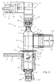
図4は、ボトル2を充填するための充填機51を示している。充填機51は、ラベル貼付ユニット40が取り除かれ、ハンドリングユニット12が取り除かれて各ハンドリングユニット52に置き換えられているという点で、図1〜図3に示されている充填機とは異なる。
FIG. 4 shows a filling
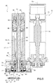
図5および図6に示されているように、各ハンドリングユニット52は、軸Bに平行な長手方向軸55を有する円筒状の垂直支柱54を備えた充填装置53を備え、カルーセル6の周辺部11に固定される。
As shown in FIGS. 5 and 6, each
支柱54は、上部幅広部57と下部狭窄部58とを備える内壁56によって半径方向に画定され、軸55と同軸の支柱54内部に取り付けられる筒状のシャッタ59と摺動係合される。
The
シャッタ59は、支柱54の下端から下に突出し、支柱54とシャッタ59自体の間に挿置される変形可能な環状膜60によって支柱54に接続される。
The
シャッタ59は支柱54と共に、支柱54とシャッタ59との間に伸び、ボトル2に供給される注入可能な製品のタンク(図示せず)に接続される管状供給ダクト61を画定する。
シャッタ59は、シャッタ59が支柱54と液密に接続されるように壁56と接触状態で配置されてダクト61を閉鎖する下降閉鎖位置と、ダクト61自体が開放している上昇開放位置との間で、軸方向に可動である。
The
シャッタ59は、軸55と同軸の支柱54とシャッタ59との間に取り付けられたばね62によって上昇開放位置まで移動され(そして、通常はその位置で維持され)、作動筒63によってばね62の作用に逆らって下降閉鎖位置まで移動される。
The
作動筒63は、軸55と同軸の支柱54内に設けられ、軸方向に角度固定した状態でシャッタ59に結合されたピストン64が設けられ、周知の空気圧装置(図示せず)に接続される。
The operating
さらに、シャッタ59は、ダクト61に沿って供給される注入可能な製品を旋回運動させるために、シャッタ59自体の外表面に設けられ、軸55に沿って(かつ軸55の周囲に)伸びる旋回翼65を有する。
In addition, a
シャッタ59は、内側供給ダクト66を画定する。ダクト66は、シャッタ59内部に伸び、ダクト66に沿ってボトル2に加圧下でガスを供給するように設計された供給装置(図示せず)に接続される。
The
さらに、充填装置53は作動筒67を備える。作動筒67は、管状形で支柱54の下部狭窄部68の周囲に伸び、軸55と同軸に取り付けられ、支柱54自体に軸方向に角度固定した状態で結合される。
Further, the filling
充填装置53は、軸55と同軸であり、作動筒67の周囲に伸び、凹面が上方を向いて配置される略円筒状ベル70を備えたボトル2の把持部材69と協働する。
The filling
ベル70は、軸方向に固定した状態で作動筒67に結合され、さらに、作動筒67自体に対して、作動装置72の推力を受けて、軸55を中心として回転するように転がり軸受71を介在させて回転可能に作動筒67に結合される。
The
作動装置72は、支柱54に固定され、軸55に平行な長手方向軸75を有する出力シャフト74が設けられた電気モータ73を備える。
The
出力シャフト74は、一対の歯車76によってベル70に結合され、歯車76のうちの一方は出力シャフト74とスプライン接続され、他方はベル70自体の外表面に設けられる。
The
さらに、把持部材69は支持板77を備え、支持板77は、ベル70から下に突出し、ベル70に固定され、関連ボトル2の上部首部4と合致して関連ボトル2を保持する構造である一対の保持ジョー78を支持する。
Further, the gripping
ジョー78は、支持板77の下に取り付けられ、支持板77とヒンジ接続されることにより、支持板77自体に対して、互いに平行かつ軸55に平行な各支点軸79を中心として回転する。
The
ジョー78は、ジョー78間に挿置されたばね80によって締め付け位置になり(そして、通常は、その位置で維持され)、関連ボトル2を把持部材69に挿入する、もしくは把持部材69から関連ボトル2を抜き取る際に関連ボトル2によってジョー78自身に加えられた推力により解除位置になる。
The
作動筒67には、作動筒67内部で摺動するように取り付けられ、下端68の周囲に伸びて、充填ヘッド82の一部を画定する空気圧式ピストン81が設けられる。
The working
充填ヘッド82は、軸方向に支柱54から下に突出し、さらに、エラストマー材料製のガスケット83を備え、ガスケット83は、軸55と同軸の環状形状であり、使用時に、ボトル2の上部首部4に面し、軸方向に固定した状態でピストン81に結合されることで、ガスケット83が上部首部4と液密に結合される下降作動位置と、ガスケット83が上部首部4自体から所定間隔離間して配置される上昇休止位置との間でピストン81によって移動される。
The filling
さらに、ガスケット83は、ボトル2の推力を受けて、ピストン81自体に対して、軸55を中心として回転するように、転がり軸受84を介在させることで回転可能にピストン81に結合される。
Further, the
この点に関して、ガスケット83は、軸受84の下方回転レース85と角度的に一体となること、およびレース85はガスケット83の上で半径方向に伸びることで、機械的摺動ガスケット87の回転リング86を画定することに留意されたい。
In this regard, the
ガスケット87は、ピストン81およびガスケット83、すなわち、充填ヘッド82の角度固定部分と回転部分とを液密に互いに結合させ、さらに、軸55と同軸のリング86の上に取り付けられる別のリング88を備える。
The
リング88は、スリーブ89の下方自由端に固定され、スリーブ89は、ピストン81に角度固定した状態で軸方向に摺動可能に結合され、ピストン81とスリーブ89自体との間に挿置されたばね90によってリング86と接触した状態で維持される。
The
関連軸55の周囲の各把持部材69の位置、ひいては関連ジョー78の位置は、移送ステーション8、10に対応して、ボトル2を正確に受け取って、正確に放すことができるように選択的に制御される。
The position of each gripping
各把持部材69の角度位置は、関連電気モータ73に結合されたエンコーダによって、もしくはベル70と協働するカム機構によって、選択的に制御される。
The angular position of each gripping
図示されていない一実施形態によれば、把持部材69は取り除かれて、関連ボトル2の下に配置され、関連軸55を中心として回転するように電動式の各下方板に置き換えられており、回転運動は、ボトル2自体によって充填ヘッド82に伝達される。この場合、ボトル2がPET製である場合、ボトル2は、好ましくは、関連軸55を中心として回転させる前に、十分な剛性になるように供給ダクト66によって加圧される。
According to one embodiment not shown, the gripping
明らかに、充填機51の全て利点は、充填機1に関して既に上述したように、充填時のボトル2の回転によって得られる。
Obviously, all the advantages of the filling
Claims (19)
搬送装置(5)と、
経路(P)に沿って搬送装置(5)によって供給される少なくとも1つのハンドリングユニット(12、52)であって、関連容器(2)を受け取って保持するための支持手段(13、69)と、ハンドリングユニット(12、52)が前記経路(P)に沿って移動している時に容器(2)に注入可能な製品を供給するための少なくとも1つの充填装置(14、53)とを備える、前記少なくとも1つのハンドリングユニット(12、52)と、
前記注入可能な製品の泡形成を低減するために、前記充填装置(14、53)によって前記注入可能な製品が容器(2)に充填される間に、長手方向軸(A)を中心として前記容器(2)を回転させるための作動手段(20、72)とを備える充填機(1)であって、
制御手段をさらに備え、前記制御手段が、少なくともハンドリングユニット(12、52)における容器(2)のピックアップステーション(8)およびハンドリングユニット(12、52)からの容器(2)の解放ステーション(10)における前記長手方向軸(A)を中心とした支持手段(13、69)の角度位置を選択的に制御することを特徴とする、充填機(1)。 A filling machine (1) for filling a container (2) having each longitudinal axis (A),
A transport device (5);
At least one handling unit (12, 52) supplied by the conveying device (5) along the path (P), the supporting means (13, 69) for receiving and holding the associated container (2); At least one filling device (14, 53) for supplying an injectable product to the container (2) when the handling unit (12, 52) is moving along the path (P). Said at least one handling unit (12, 52);
In order to reduce foam formation of the injectable product, the filling device (14, 53) fills the container (2) with the injectable product while the longitudinal axis (A) is the center. A filling machine (1) comprising actuating means (20, 72) for rotating the container (2),
The control means further comprises a pick-up station (8) for the container (2) at least in the handling unit (12, 52) and a release station (10) for the container (2) from the handling unit (12, 52). A filling machine (1), characterized in that the angular position of the support means (13, 69) about the longitudinal axis (A) is selectively controlled.
経路(P)に沿って少なくとも1つのハンドリングユニット(12、52)を前進させるステップと、
前記経路(P)に沿って保持され前進する前記ハンドリングユニット(12、52)に少なくとも1つの容器(2)を供給するステップと、
前記ハンドリングユニット(12、52)の充填装置(14、53)を作動させることによって、前記容器(2)に注入可能な製品を充填する充填ステップであって、ハンドリングユニット(12、52)が前記経路(P)に沿って前進する間に行われる、前記充填ステップと、
注入可能な製品の泡形成を低減するために、前記充填ステップの時に、前記容器(2)を前記長手方向軸(A)を中心として回転させるステップとを含み、
前記容器(2)の長手方向軸(A)を中心とした回転は、前記ハンドリングユニット(12、52)の少なくとも一部(13、25、26、69)を前記長手方向軸(A)と同軸の回転軸(E、55)を中心として回転させることによって行われる充填方法であって、
少なくともハンドリングユニット(12、52)における容器(2)のピックアップステーション(8)およびハンドリングユニット(12、52)からの容器(2)の解放ステーション(10)における前記長手方向軸(A)を中心とした前記ハンドリングユニット(12、52)の前記一部(13、25、26、69)の角度位置を選択的に制御するステップをさらに含むことを特徴とする、充填方法。 In a filling method of filling a container (2) having each longitudinal axis (A),
Advancing at least one handling unit (12, 52) along path (P);
Supplying at least one container (2) to the handling unit (12, 52) held and advanced along the path (P);
A filling step of filling the container (2) with an injectable product by operating a filling device (14, 53) of the handling unit (12, 52), wherein the handling unit (12, 52) is Said filling step performed while advancing along path (P);
Rotating the container (2) about the longitudinal axis (A) during the filling step to reduce foam formation of the injectable product ;
The rotation of the container (2) about the longitudinal axis (A) causes at least a part (13, 25, 26, 69) of the handling unit (12, 52) to be coaxial with the longitudinal axis (A). A filling method performed by rotating around the rotation axis (E, 55) of
Centered on the longitudinal axis (A) at least in the pick-up station (8) of the container (2) in the handling unit (12, 52) and the release station (10) of the container (2) from the handling unit (12, 52). The filling method further comprising the step of selectively controlling the angular position of said part (13, 25, 26, 69) of said handling unit (12, 52).
Applications Claiming Priority (3)
| Application Number | Priority Date | Filing Date | Title |
|---|---|---|---|
| EP12199777.9 | 2012-12-28 | ||
| EP12199777.9A EP2749501B1 (en) | 2012-12-28 | 2012-12-28 | A machine and a method for filling and labelling containers |
| PCT/EP2013/076619 WO2014102075A1 (en) | 2012-12-28 | 2013-12-13 | A machine and a method for filling containers |
Publications (3)
| Publication Number | Publication Date |
|---|---|
| JP2016501795A JP2016501795A (en) | 2016-01-21 |
| JP2016501795A5 JP2016501795A5 (en) | 2016-08-25 |
| JP6321677B2 true JP6321677B2 (en) | 2018-05-09 |
Family
ID=47715796
Family Applications (1)
| Application Number | Title | Priority Date | Filing Date |
|---|---|---|---|
| JP2015550022A Active JP6321677B2 (en) | 2012-12-28 | 2013-12-13 | Container filling machine and container filling method |
Country Status (5)
| Country | Link |
|---|---|
| US (2) | US9758361B2 (en) |
| EP (3) | EP2749501B1 (en) |
| JP (1) | JP6321677B2 (en) |
| CN (1) | CN104884352B (en) |
| WO (1) | WO2014102075A1 (en) |
Families Citing this family (29)
| Publication number | Priority date | Publication date | Assignee | Title |
|---|---|---|---|---|
| DE102013103111A1 (en) * | 2013-03-26 | 2014-10-02 | George Robert Collins | Holder for a container receptacle and container receptacle |
| KR20160106675A (en) * | 2014-01-08 | 2016-09-12 | 애버리 데니슨 코포레이션 | Articles, compositions, systems, and methods using selectively detackified adhesives |
| EP3118131B1 (en) * | 2015-07-16 | 2018-01-31 | Sidel Participations | A machine and a method for filling containers |
| EP3124428A1 (en) * | 2015-07-31 | 2017-02-01 | Sidel Participations | A machine for filling containers |
| US20170029261A1 (en) * | 2015-07-31 | 2017-02-02 | Spraying Systems Co. | System for filling liquid containing bottles |
| EP3135628B1 (en) * | 2015-08-31 | 2017-12-13 | Sidel Participations | A machine for filling containers |
| EP3144234A1 (en) * | 2015-09-21 | 2017-03-22 | Sidel Participations | An apparatus for producing plastic bottles |
| EP3153419B1 (en) * | 2015-10-05 | 2018-06-06 | Sidel Participations | A method and an apparatus for handling receptacles |
| EP3162721A1 (en) * | 2015-11-02 | 2017-05-03 | Sidel Participations | An apparatus for handling receptacles |
| EP3176126B1 (en) * | 2015-12-04 | 2018-08-08 | Sidel Participations | A filling device for a filling machine |
| CN108290728A (en) * | 2015-12-07 | 2018-07-17 | 雀巢产品技术援助有限公司 | For filling and the device and method of sealing container |
| DE102015224972A1 (en) | 2015-12-11 | 2017-06-14 | Krones Aktiengesellschaft | Container treatment plant with a filler |
| BR112018017190A2 (en) | 2016-02-22 | 2019-01-02 | Avery Dennison Corp | extended content transparent label with selectively reduced adhesive |
| JP6685162B2 (en) * | 2016-03-31 | 2020-04-22 | サントリーホールディングス株式会社 | Removal jig |
| CN106347796A (en) * | 2016-08-30 | 2017-01-25 | 贵州凯吉通医药包装机械有限公司 | Automatic labeling structure |
| MX2019002777A (en) | 2016-09-09 | 2019-08-29 | Procter & Gamble | System and method for producing products based upon demand. |
| WO2018049143A1 (en) * | 2016-09-09 | 2018-03-15 | The Procter & Gamble Company | System and method for independently routing vehicles and delivering containers and closures to unit operation stations |
| IT201600128045A1 (en) * | 2016-12-19 | 2018-06-19 | Weightpack Srl | NET WEIGHT FILLING MACHINE WITH VOLUMETRIC PUMP |
| EP3348377B1 (en) * | 2017-01-12 | 2019-10-09 | Sidel Participations | Receptacle conveying and cooling apparatus, a method of operating such a receptacle conveying and cooling apparatus and a receptacle treatment machine having such a receptacle conveying and cooling apparatus |
| USD846608S1 (en) * | 2017-03-14 | 2019-04-23 | M&M Machinery Services, Inc. | Receiver for a bottling machine |
| IT201700089679A1 (en) * | 2017-08-03 | 2019-02-03 | Gea Procomac Spa | SYSTEM TO PRODUCE STERILE VESSELS, BOTTLING SYSTEM INCLUDING THIS EQUIPMENT AND METHOD TO PRODUCE A STERILE CONTAINER |
| EP3473590B1 (en) | 2017-10-19 | 2020-02-12 | Sidel Participations | Improved filling device for a filling machine |
| JP2019094098A (en) * | 2017-11-22 | 2019-06-20 | 澁谷工業株式会社 | Filling valve |
| IT201900000361A1 (en) * | 2019-01-10 | 2020-07-10 | Makro Labelling Srl | Machine for the treatment and / or handling of objects, in particular containers, and related method |
| CN111892003B (en) * | 2020-08-28 | 2021-10-15 | 泉州市创智工业设计服务有限公司 | Filling device is used in cosmetics production |
| CN112456416B (en) * | 2020-11-02 | 2022-07-01 | 安徽独秀山蓝莓科技开发有限公司 | Blueberry wine filling and sealing equipment |
| US20220315264A1 (en) * | 2021-03-31 | 2022-10-06 | Accraply, Llc | Machine For Applying Labels Or Other Markings To Containers |
| CN115320972B (en) * | 2021-05-11 | 2023-11-24 | 菜鸟智能物流控股有限公司 | Labeling device and automatic labeling machine |
| CN113233405B (en) * | 2021-06-02 | 2023-05-09 | 湖南堂家巷子食品科技有限公司 | Full-automatic production line for filled food |
Family Cites Families (17)
| Publication number | Priority date | Publication date | Assignee | Title |
|---|---|---|---|---|
| US3516455A (en) * | 1967-05-01 | 1970-06-23 | Automatic Sprinkler Corp | Container-filling apparatus |
| FR2151725A5 (en) * | 1971-09-10 | 1973-04-20 | Bedin Jean | |
| DE2539857B2 (en) * | 1975-09-08 | 1981-04-09 | Wüma Maschinenbau GmbH, 6805 Heddesheim | Device for filling and labeling containers such as bottles or cans |
| DE3927489A1 (en) * | 1989-08-21 | 1991-02-28 | Alfill Getraenketechnik | DEVICE FOR FILLING CONTAINERS |
| EP1184160A3 (en) * | 1997-04-30 | 2002-03-20 | Mitsubishi Heavy Industries, Ltd. | Transportation, feeding and filling apparatus of irregular-formed vessels and transportation and feeding method |
| US6338371B1 (en) * | 1997-04-30 | 2002-01-15 | Mitsubishi Heavy Industries, Ltd. | Apparatus for conveying, supplying, and filling unshaped containers, and method for conveying and supplying the same |
| JP4232265B2 (en) * | 1999-03-29 | 2009-03-04 | 澁谷工業株式会社 | Resin bottle transfer processing system |
| ITMI20010838A1 (en) * | 2001-04-20 | 2002-10-20 | Sasib Labelling Machinery S P | DEVICE FOR TAKING AND HANDLING BOTTLES IN A LABELING MACHINE AND PROCEDURE FOR FILLING / PRESSURIZING BOTTLES |
| ITBO20020523A1 (en) * | 2002-08-05 | 2004-02-06 | Azionaria Costruzioni Acma Spa | MACHINE FOR FILLING CONTAINERS. |
| EP1867600B1 (en) * | 2006-06-14 | 2009-03-25 | Sidel Holdings & Technology S.A. | Gripper for containers |
| DE102006055317B4 (en) * | 2006-11-23 | 2010-09-30 | Khs Ag | Device for container transport with a rotating inlet disc |
| JP4952408B2 (en) | 2007-06-29 | 2012-06-13 | 澁谷工業株式会社 | Container carrier |
| IT1393171B1 (en) * | 2009-02-13 | 2012-04-11 | Berchi Group S P A | HOT BOTTLE FILLING PLANT. |
| EP2454186A1 (en) * | 2009-07-14 | 2012-05-23 | Sidel S.p.a. Con Socio Unico | Filling valve |
| DE102009058085A1 (en) * | 2009-12-14 | 2011-06-16 | Krones Ag | Labeling device and labeling method for labeling containers with sterilization device |
| CN201605151U (en) * | 2010-02-04 | 2010-10-13 | 广州达意隆包装机械股份有限公司 | Filling device with controllable filling speed |
| US8852370B2 (en) * | 2010-03-04 | 2014-10-07 | Sidel S.P.A. Con Socio Unico | Labelling machine and method thereof |
-
2012
- 2012-12-28 EP EP12199777.9A patent/EP2749501B1/en active Active
-
2013
- 2013-12-13 JP JP2015550022A patent/JP6321677B2/en active Active
- 2013-12-13 CN CN201380068935.7A patent/CN104884352B/en active Active
- 2013-12-13 WO PCT/EP2013/076619 patent/WO2014102075A1/en active Application Filing
- 2013-12-13 US US14/758,132 patent/US9758361B2/en active Active
- 2013-12-13 EP EP16194069.7A patent/EP3156341A1/en not_active Withdrawn
- 2013-12-13 EP EP13805379.8A patent/EP2938545B1/en active Active
-
2017
- 2017-09-11 US US15/700,763 patent/US20170369297A1/en not_active Abandoned
Also Published As
| Publication number | Publication date |
|---|---|
| EP2938545A1 (en) | 2015-11-04 |
| EP2749501B1 (en) | 2017-08-02 |
| CN104884352B (en) | 2016-12-07 |
| EP3156341A1 (en) | 2017-04-19 |
| CN104884352A (en) | 2015-09-02 |
| JP2016501795A (en) | 2016-01-21 |
| EP2938545B1 (en) | 2017-02-08 |
| US9758361B2 (en) | 2017-09-12 |
| EP2749501A1 (en) | 2014-07-02 |
| WO2014102075A1 (en) | 2014-07-03 |
| US20160194189A1 (en) | 2016-07-07 |
| US20170369297A1 (en) | 2017-12-28 |
Similar Documents
| Publication | Publication Date | Title |
|---|---|---|
| JP6321677B2 (en) | Container filling machine and container filling method | |
| US10017370B2 (en) | Machine and method for filling containers | |
| US10773446B2 (en) | Apparatus for producing plastic bottles | |
| US6082418A (en) | Aseptic container filling assembly | |
| EP2445825B1 (en) | Liquid bottling method and machine, in particular for carbonated liquids or oxygen sensitive liquids | |
| EP3153419B1 (en) | A method and an apparatus for handling receptacles | |
| EP3199490B1 (en) | Receptacle handling apparatus for filling and capping receptacles | |
| US10106281B2 (en) | Receptacle conveying and cooling apparatus, a method of operating such a receptacle conveying and cooling apparatus and a receptacle treatment machine having such a receptacle conveying and cooling apparatus | |
| EP3162721A1 (en) | An apparatus for handling receptacles | |
| EP4074649B1 (en) | Capping device and capping method | |
| EP3453629A1 (en) | Method and machine for filling and capping receptacles | |
| EP3357859A1 (en) | Filling valve, filling apparatus having such a filling valve and method of operating such a filling valve | |
| EP3026007A1 (en) | A filling head for filling containers | |
| EP2746216B1 (en) | An apparatus and a method for filling containers | |
| US20170029259A1 (en) | Machine for filling containers |
Legal Events
| Date | Code | Title | Description |
|---|---|---|---|
| A521 | Request for written amendment filed |
Free format text: JAPANESE INTERMEDIATE CODE: A523 Effective date: 20160707 |
|
| A621 | Written request for application examination |
Free format text: JAPANESE INTERMEDIATE CODE: A621 Effective date: 20160707 |
|
| A977 | Report on retrieval |
Free format text: JAPANESE INTERMEDIATE CODE: A971007 Effective date: 20170627 |
|
| A131 | Notification of reasons for refusal |
Free format text: JAPANESE INTERMEDIATE CODE: A131 Effective date: 20170704 |
|
| A521 | Request for written amendment filed |
Free format text: JAPANESE INTERMEDIATE CODE: A523 Effective date: 20171003 |
|
| TRDD | Decision of grant or rejection written | ||
| A01 | Written decision to grant a patent or to grant a registration (utility model) |
Free format text: JAPANESE INTERMEDIATE CODE: A01 Effective date: 20180327 |
|
| A61 | First payment of annual fees (during grant procedure) |
Free format text: JAPANESE INTERMEDIATE CODE: A61 Effective date: 20180405 |
|
| R150 | Certificate of patent or registration of utility model |
Ref document number: 6321677 Country of ref document: JP Free format text: JAPANESE INTERMEDIATE CODE: R150 |
|
| R250 | Receipt of annual fees |
Free format text: JAPANESE INTERMEDIATE CODE: R250 |
|
| R250 | Receipt of annual fees |
Free format text: JAPANESE INTERMEDIATE CODE: R250 |
|
| R250 | Receipt of annual fees |
Free format text: JAPANESE INTERMEDIATE CODE: R250 |