JP6319009B2 - Cooling system - Google Patents

Cooling system Download PDF

Info

Publication number
JP6319009B2
JP6319009B2 JP2014191045A JP2014191045A JP6319009B2 JP 6319009 B2 JP6319009 B2 JP 6319009B2 JP 2014191045 A JP2014191045 A JP 2014191045A JP 2014191045 A JP2014191045 A JP 2014191045A JP 6319009 B2 JP6319009 B2 JP 6319009B2
Authority
JP
Japan
Prior art keywords
air
vehicle
outside air
engine
passage
Prior art date
Legal status (The legal status is an assumption and is not a legal conclusion. Google has not performed a legal analysis and makes no representation as to the accuracy of the status listed.)
Active
Application number
JP2014191045A
Other languages
Japanese (ja)
Other versions
JP2016060410A (en
JP2016060410A5 (en
Inventor
雄史 川口
雄史 川口
位司 安田
位司 安田
Current Assignee (The listed assignees may be inaccurate. Google has not performed a legal analysis and makes no representation or warranty as to the accuracy of the list.)
Denso Corp
Original Assignee
Denso Corp
Priority date (The priority date is an assumption and is not a legal conclusion. Google has not performed a legal analysis and makes no representation as to the accuracy of the date listed.)
Filing date
Publication date
Application filed by Denso Corp filed Critical Denso Corp
Priority to JP2014191045A priority Critical patent/JP6319009B2/en
Priority to DE112015004248.2T priority patent/DE112015004248B4/en
Priority to PCT/JP2015/004253 priority patent/WO2016042709A1/en
Publication of JP2016060410A publication Critical patent/JP2016060410A/en
Publication of JP2016060410A5 publication Critical patent/JP2016060410A5/ja
Application granted granted Critical
Publication of JP6319009B2 publication Critical patent/JP6319009B2/en
Active legal-status Critical Current
Anticipated expiration legal-status Critical

Links

Images

Classifications

    • BPERFORMING OPERATIONS; TRANSPORTING
    • B60VEHICLES IN GENERAL
    • B60KARRANGEMENT OR MOUNTING OF PROPULSION UNITS OR OF TRANSMISSIONS IN VEHICLES; ARRANGEMENT OR MOUNTING OF PLURAL DIVERSE PRIME-MOVERS IN VEHICLES; AUXILIARY DRIVES FOR VEHICLES; INSTRUMENTATION OR DASHBOARDS FOR VEHICLES; ARRANGEMENTS IN CONNECTION WITH COOLING, AIR INTAKE, GAS EXHAUST OR FUEL SUPPLY OF PROPULSION UNITS IN VEHICLES
    • B60K11/00Arrangement in connection with cooling of propulsion units
    • B60K11/02Arrangement in connection with cooling of propulsion units with liquid cooling
    • B60K11/04Arrangement or mounting of radiators, radiator shutters, or radiator blinds
    • BPERFORMING OPERATIONS; TRANSPORTING
    • B60VEHICLES IN GENERAL
    • B60HARRANGEMENTS OF HEATING, COOLING, VENTILATING OR OTHER AIR-TREATING DEVICES SPECIALLY ADAPTED FOR PASSENGER OR GOODS SPACES OF VEHICLES
    • B60H1/00Heating, cooling or ventilating [HVAC] devices
    • B60H1/00271HVAC devices specially adapted for particular vehicle parts or components and being connected to the vehicle HVAC unit
    • BPERFORMING OPERATIONS; TRANSPORTING
    • B60VEHICLES IN GENERAL
    • B60KARRANGEMENT OR MOUNTING OF PROPULSION UNITS OR OF TRANSMISSIONS IN VEHICLES; ARRANGEMENT OR MOUNTING OF PLURAL DIVERSE PRIME-MOVERS IN VEHICLES; AUXILIARY DRIVES FOR VEHICLES; INSTRUMENTATION OR DASHBOARDS FOR VEHICLES; ARRANGEMENTS IN CONNECTION WITH COOLING, AIR INTAKE, GAS EXHAUST OR FUEL SUPPLY OF PROPULSION UNITS IN VEHICLES
    • B60K11/00Arrangement in connection with cooling of propulsion units
    • B60K11/06Arrangement in connection with cooling of propulsion units with air cooling
    • BPERFORMING OPERATIONS; TRANSPORTING
    • B60VEHICLES IN GENERAL
    • B60KARRANGEMENT OR MOUNTING OF PROPULSION UNITS OR OF TRANSMISSIONS IN VEHICLES; ARRANGEMENT OR MOUNTING OF PLURAL DIVERSE PRIME-MOVERS IN VEHICLES; AUXILIARY DRIVES FOR VEHICLES; INSTRUMENTATION OR DASHBOARDS FOR VEHICLES; ARRANGEMENTS IN CONNECTION WITH COOLING, AIR INTAKE, GAS EXHAUST OR FUEL SUPPLY OF PROPULSION UNITS IN VEHICLES
    • B60K11/00Arrangement in connection with cooling of propulsion units
    • B60K11/08Air inlets for cooling; Shutters or blinds therefor
    • B60K11/085Air inlets for cooling; Shutters or blinds therefor with adjustable shutters or blinds
    • FMECHANICAL ENGINEERING; LIGHTING; HEATING; WEAPONS; BLASTING
    • F01MACHINES OR ENGINES IN GENERAL; ENGINE PLANTS IN GENERAL; STEAM ENGINES
    • F01PCOOLING OF MACHINES OR ENGINES IN GENERAL; COOLING OF INTERNAL-COMBUSTION ENGINES
    • F01P1/00Air cooling
    • F01P1/06Arrangements for cooling other engine or machine parts
    • BPERFORMING OPERATIONS; TRANSPORTING
    • B60VEHICLES IN GENERAL
    • B60HARRANGEMENTS OF HEATING, COOLING, VENTILATING OR OTHER AIR-TREATING DEVICES SPECIALLY ADAPTED FOR PASSENGER OR GOODS SPACES OF VEHICLES
    • B60H1/00Heating, cooling or ventilating [HVAC] devices
    • B60H1/00271HVAC devices specially adapted for particular vehicle parts or components and being connected to the vehicle HVAC unit
    • B60H2001/003Component temperature regulation using an air flow
    • FMECHANICAL ENGINEERING; LIGHTING; HEATING; WEAPONS; BLASTING
    • F01MACHINES OR ENGINES IN GENERAL; ENGINE PLANTS IN GENERAL; STEAM ENGINES
    • F01PCOOLING OF MACHINES OR ENGINES IN GENERAL; COOLING OF INTERNAL-COMBUSTION ENGINES
    • F01P1/00Air cooling
    • F01P2001/005Cooling engine rooms
    • YGENERAL TAGGING OF NEW TECHNOLOGICAL DEVELOPMENTS; GENERAL TAGGING OF CROSS-SECTIONAL TECHNOLOGIES SPANNING OVER SEVERAL SECTIONS OF THE IPC; TECHNICAL SUBJECTS COVERED BY FORMER USPC CROSS-REFERENCE ART COLLECTIONS [XRACs] AND DIGESTS
    • Y02TECHNOLOGIES OR APPLICATIONS FOR MITIGATION OR ADAPTATION AGAINST CLIMATE CHANGE
    • Y02TCLIMATE CHANGE MITIGATION TECHNOLOGIES RELATED TO TRANSPORTATION
    • Y02T10/00Road transport of goods or passengers
    • Y02T10/80Technologies aiming to reduce greenhouse gasses emissions common to all road transportation technologies
    • Y02T10/88Optimized components or subsystems, e.g. lighting, actively controlled glasses

Description

本発明は、エンジン後部の後方排気部を冷却する冷却装置に関する。   The present invention relates to a cooling device that cools a rear exhaust portion at the rear of an engine.

特許文献1のエンジンルーム構造によれば、車両前部のラジエータファンによって後方に送風される外気が流れるダクトをエンジンの前方から後方にかけて配設することが開示されている。このダクト内部の通路には、エンジンの前部から延びる排気マニホールド及びこのマニホールドから後方に延びる排気パイプが設けられている。ラジエータファンによってエンジンルームに取り込まれた外気は、ダクト内を後方へ流れることで、排気マニホールド及び排気パイプに接触してこれらを冷却することができる。   According to the engine room structure of Patent Document 1, it is disclosed that a duct through which outside air blown rearward by a radiator fan at the front of a vehicle flows is arranged from the front to the rear of the engine. An exhaust manifold extending from the front portion of the engine and an exhaust pipe extending rearward from the manifold are provided in a passage inside the duct. The outside air taken into the engine room by the radiator fan flows backward in the duct, and can contact the exhaust manifold and the exhaust pipe to cool them.

特開平05−169986号公報Japanese Patent Laid-Open No. 05-169986

特許文献1の技術では、エンジンの前部から延びる排気マニホールドについて、ラジエータファンによって後方に送風される空気を用いて冷却することで、エンジン前面側の排気マニホールドで熱交換された熱気がエンジン背面に回り込むことを抑制する。このように特許文献1に開示の技術では、エンジン後部から排気が行われる後方排気部を構成するエンジン後部の排気マニホールド、当該マニホールドから後方へ延びる排気パイプ等について、十分な冷却を行うことができない。特に、後方排気型のエンジンに関して後方排気部の冷却を効率的に行うことは、重要な技術課題であり、さらなる改良が求められている。   In the technique of Patent Document 1, the exhaust manifold extending from the front portion of the engine is cooled using air blown rearward by a radiator fan, so that the hot air heat-exchanged by the exhaust manifold on the front side of the engine is transferred to the rear surface of the engine. Suppresses wraparound. As described above, the technique disclosed in Patent Document 1 cannot sufficiently cool the exhaust manifold at the rear of the engine that constitutes the rear exhaust that exhausts from the rear of the engine, the exhaust pipe that extends rearward from the manifold, and the like. . In particular, efficient cooling of the rear exhaust portion of a rear exhaust type engine is an important technical issue, and further improvement is required.

そこで、本発明は、前述の問題点に鑑みてなされたものであり、エンジンの後部から排気が流れる後方排気部を効率的に排気可能な冷却装置を提供することを目的とする。   Therefore, the present invention has been made in view of the above-described problems, and an object of the present invention is to provide a cooling device capable of efficiently exhausting a rear exhaust part through which exhaust flows from the rear part of an engine.

本発明は上記目的を達成するために以下の技術的手段を採用する。なお、特許請求の範囲及びこの項に記載した括弧内の符号は、ひとつの態様として後述する実施形態に記載の具体的手段との対応関係を示す一例であって、本発明の技術的範囲を限定するものではない。   The present invention employs the following technical means to achieve the above object. It should be noted that the reference numerals in parentheses described in the claims and in this section are examples showing the correspondence with the specific means described in the embodiments described later as one aspect, and the technical scope of the present invention is as follows. It is not limited.

開示された冷却装置に係る発明のひとつは、車両に搭載され、エンジン後部から後方に向けて排気が流れる排気通路を構成する後方排気部(20、21)を有するエンジン(2)と、車外とエンジンが設置されるエンジンルーム(4)とを連絡する通路であって、車外から取り込まれる外気が後方排気部に向けて流入するように、エンジンの後部寄りに設けられた外気導入通路(31)と、外気導入通路において空気の流通を許容する開状態と阻止する閉状態とに制御可能な通路開閉装置(3)と、車室内を空調するための車両用空調装置(1)において空調された空調空気を、エンジンよりも後方から後方排気部に向けて流入させるように設けられた空調風導入通路(11)と、車両用空調装置の運転と通路開閉装置の作動とを制御する制御装置(100)と、を備え
制御装置は、停車中に、通路開閉装置を開状態に制御するとともに、車両用空調装置において冷却された冷気を空調風導入通路に流すように車両用空調装置の運転を制御することを特徴とする。
One of the inventions related to the disclosed cooling device includes an engine (2) that is mounted on a vehicle and has a rear exhaust part (20, 21) that constitutes an exhaust passage through which exhaust flows from the rear of the engine toward the rear, An outside air introduction passage (31) provided near the rear of the engine so as to allow the outside air taken in from the outside of the vehicle to flow toward the rear exhaust part. And the passage opening and closing device (3) that can be controlled to be open and closed to allow air flow in the outside air introduction passage, and the vehicle air conditioner (1) for air conditioning the vehicle interior. The conditioned air introduction passage (11) provided to allow the conditioned air to flow from the rear toward the rear exhaust part from the engine, and the control of the operation of the vehicle air conditioner and the operation of the passage opening / closing device. Apparatus (100) comprises a,
The control device controls the operation of the vehicle air conditioner so that the cool air cooled in the vehicle air conditioner flows into the conditioned air introduction passage while the passage opening and closing device is controlled to be open while the vehicle is stopped. To do.

この発明によれば、エンジンの後部寄りに設定された外気導入通路に外気を導入することにより、外気流入時の通風抵抗を少なくしてスムーズにエンジンルームに取り入れることができる。さらに外気導入通路に流入した外気は、後方排気部に向けて流れるため、冷却効果の高い新鮮な外気をエンジンルームの他の熱源から吸熱する前に後方排気部に接触させることができる。これにより、外気によって後方排気部を冷却する効果を格段に高めることが可能である。例えば、車両走行時には、通路開閉装置を開状態にすることにより、外気が車外から外気導入通路を通って後方排気部に向けて流れ得るので、後方排気型のエンジンの排気マニホールドや排気パイプを冷却する能力を外気によって向上させることができる。   According to the present invention, by introducing the outside air into the outside air introduction passage set near the rear part of the engine, it is possible to reduce the ventilation resistance when the outside air flows in and smoothly take it into the engine room. Furthermore, since the outside air that has flowed into the outside air introduction passage flows toward the rear exhaust portion, fresh outside air having a high cooling effect can be brought into contact with the rear exhaust portion before absorbing heat from another heat source in the engine room. Thereby, it is possible to remarkably enhance the effect of cooling the rear exhaust part by the outside air. For example, when the vehicle is running, by opening the passage opening and closing device, outside air can flow from outside the vehicle through the outside air introduction passage toward the rear exhaust section, so that the exhaust manifold and exhaust pipe of the rear exhaust type engine are cooled. The ability to do can be improved by the outside air.

以上のように、この発明によれば、エンジン後部から排気が流れる後方排気部を効率的に排気できる冷却装置を提供できる。   As described above, according to the present invention, it is possible to provide a cooling device that can efficiently exhaust the rear exhaust part through which exhaust flows from the rear part of the engine.

本発明に係る冷却装置の一例である第1実施形態であり、走行時に外気導入を行う状態を示した図面である。It is 1st Embodiment which is an example of the cooling device which concerns on this invention, and is drawing which showed the state which introduces external air at the time of driving | running | working. 第1実施形態において、走行時に外気導入を行わない状態を示した図面である。In 1st Embodiment, it is drawing which showed the state which does not introduce external air at the time of driving | running | working. 第1実施形態において、停車時に外気導入を行う状態を示した図面である。In 1st Embodiment, it is drawing which showed the state which introduces external air at the time of a stop. 第1実施形態における冷却装置の制御に関するブロック図である。It is a block diagram regarding control of the cooling device in a 1st embodiment. 第1実施形態の冷却装置が行う制御に関するフローチャートである。It is a flowchart regarding the control which the cooling device of 1st Embodiment performs. 第2実施形態において、停車時に外気導入を行う状態を示した図面である。In 2nd Embodiment, it is drawing which showed the state which introduces external air at the time of a stop. 第2実施形態における冷却装置の制御に関するブロック図である。It is a block diagram regarding control of the cooling device in 2nd Embodiment. 第2実施形態の冷却装置が行う制御に関するフローチャートである。It is a flowchart regarding the control which the cooling device of 2nd Embodiment performs.

以下に、図面を参照しながら本発明を実施するための複数の形態を説明する。各形態において先行する形態で説明した事項に対応する部分には同一の参照符号を付して重複する説明を省略する場合がある。各形態において構成の一部のみを説明している場合は、構成の他の部分については先行して説明した他の形態を適用することができる。各実施形態で具体的に組み合わせが可能であることを明示している部分同士の組み合わせばかりではなく、特に組み合わせに支障が生じなければ、明示してなくとも実施形態同士を部分的に組み合わせることも可能である。   A plurality of modes for carrying out the present invention will be described below with reference to the drawings. In each embodiment, parts corresponding to the matters described in the preceding embodiment may be denoted by the same reference numerals, and redundant description may be omitted. When only a part of the configuration is described in each mode, the other modes described above can be applied to the other parts of the configuration. In addition to combinations of parts that clearly indicate that each embodiment can be combined specifically, the embodiments may be partially combined even if they are not clearly specified, unless there is a problem with the combination. Is possible.

(第1実施形態)
開示発明に係る第1実施形態の冷却装置は、車両走行のための動力を提供するエンジン2において、エンジン後部から後方に向けて排気が流れる部分である後方排気部を効率的に冷却できる装置である。冷却対象とする後方排気部は、エンジン2の後部に接続される排気通路である。後方排気部には、例えば、エンジン後部から後方へ排気が流出する多岐管の排気マニホールド20や、排気マニホールド20に接続されて後方に延びる排気パイプ21が含まれる。
(First embodiment)
The cooling device according to the first embodiment of the disclosed invention is a device that can efficiently cool a rear exhaust portion, which is a portion in which exhaust flows from the rear of the engine toward the rear, in the engine 2 that provides power for vehicle travel. is there. The rear exhaust part to be cooled is an exhaust passage connected to the rear part of the engine 2. The rear exhaust unit includes, for example, a manifold exhaust manifold 20 from which exhaust flows out rearward from the rear of the engine, and an exhaust pipe 21 connected to the exhaust manifold 20 and extending rearward.

第1実施形態に係る冷却装置について、図1〜図5を参照して説明する。車両のエンジンルーム4は、前部のフロントグリル41、側部のフードリッジパネル、上部のエンジンフード40(またはボンネット)、下部のアンダーカバー45及び後部のファイアウォール47等で囲まれたエンジン2の収容空間である。アンダーカバー45は、フロントグリル41の下方部から車両後方へファイアウォール47の近傍まで延びている。ファイアウォール47は、エンジンルーム4と運転席の間の仕切りパネルを構成する。   The cooling device according to the first embodiment will be described with reference to FIGS. The engine room 4 of the vehicle accommodates the engine 2 surrounded by a front front grill 41, a side hood ridge panel, an upper engine hood 40 (or bonnet), a lower under cover 45, a rear firewall 47, and the like. It is space. The under cover 45 extends from the lower part of the front grill 41 to the vicinity of the firewall 47 in the rear of the vehicle. The firewall 47 constitutes a partition panel between the engine room 4 and the driver's seat.

例えば、ファイアウォール47には、フロアパネル46が一体に設けられる。フロアパネル46は、車室内5の下方で車両の底部を構成する。アンダーカバー45、ファイアウォール47及びフロアパネル46は、車両の車幅全体にわたって設けられている。アンダーカバー45とフロアパネル46との隙間は、前述の後方排気部を冷却するために車外から取り込まれた外気がエンジンルーム4から排出される外気排出用の開口を構成する。   For example, the floor panel 46 is integrally provided in the firewall 47. The floor panel 46 constitutes the bottom of the vehicle below the vehicle interior 5. The under cover 45, the firewall 47, and the floor panel 46 are provided over the entire vehicle width. A gap between the under cover 45 and the floor panel 46 constitutes an opening for discharging outside air through which outside air taken in from the outside of the vehicle is discharged from the engine room 4 in order to cool the above-described rear exhaust portion.

エンジンルーム4の前部であるエンジン2の前方には、車両のフレーム等に固定されたクーリングモジュールが設けられている。クーリングモジュールは、空調装置1に用いられるコンデンサ42の冷却とエンジン2の冷却水を冷却するラジエータ43の冷却とを、共通の電動ファン44による強制送風により行う。クーリングモジュールには、コンデンサ42がラジエータ43の前面に配置される直列配列が採用されている。コンデンサ42はラジエータ43のボディにゴムマウントを介して固定されている。また、電動ファン44は、ファンシュラウドを有し、ラジエータ43の背後でラジエータ43に一体に固定されている。   A cooling module fixed to a vehicle frame or the like is provided in front of the engine 2 which is a front portion of the engine room 4. The cooling module performs cooling of the condenser 42 used in the air conditioner 1 and cooling of the radiator 43 that cools the cooling water of the engine 2 by forced air blowing by a common electric fan 44. The cooling module employs a series arrangement in which the capacitor 42 is disposed on the front surface of the radiator 43. The capacitor 42 is fixed to the body of the radiator 43 via a rubber mount. The electric fan 44 has a fan shroud, and is fixed to the radiator 43 integrally behind the radiator 43.

エンジン2は、その後部から排気を行う排気マニホールド20を少なくとも有する。排気マニホールド20には、エンジンルーム4の後部でファイアウォール47に近接して下方に延びる排気パイプ21が接続されている。排気パイプ21は、フロアパネル46に沿うように車両後部まで延びており、車両後部のバンパと一体となった開口端部から排気が車外に排出される。排気マニホールド20と排気パイプ21は、エンジン2から流出した排気が流れるエンジン2の排気管とも呼ばれる。冷却装置が冷却対象とする後方排気部には、排気マニホールド20及び排気パイプ21の少なくとも一方が含まれる。   The engine 2 has at least an exhaust manifold 20 that performs exhaust from its rear part. Connected to the exhaust manifold 20 is an exhaust pipe 21 that extends downward in the vicinity of the firewall 47 at the rear of the engine room 4. The exhaust pipe 21 extends to the rear of the vehicle along the floor panel 46, and the exhaust is discharged out of the vehicle through an opening end integrated with a bumper at the rear of the vehicle. The exhaust manifold 20 and the exhaust pipe 21 are also called the exhaust pipe of the engine 2 through which the exhaust gas flowing out from the engine 2 flows. The rear exhaust part to be cooled by the cooling device includes at least one of the exhaust manifold 20 and the exhaust pipe 21.

電動ファン44によって、フロントグリル41から吸い込まれた外気は、コンデンサ42の熱交換コア部、ラジエータ43の熱交換コア部を順に通過して、エンジン2の前面側に流れる。この外気は、エンジン2の前部に接触してこれを冷却した後、エンジン2の後部側にも接触して、アンダーカバー45とフロアパネル46との隙間による前述の開口からエンジンルーム4の外に排出される。   The outside air sucked from the front grill 41 by the electric fan 44 passes through the heat exchange core portion of the condenser 42 and the heat exchange core portion of the radiator 43 in this order, and flows to the front side of the engine 2. This outside air contacts the front part of the engine 2 and cools it, and then also contacts the rear side of the engine 2, and the outside of the engine room 4 from the above opening due to the gap between the under cover 45 and the floor panel 46. To be discharged.

このように、電動ファン44によってエンジンルーム4に導入された外気は、エンジン2の後部側に設けられる後方排気部にも接触しうるため、後方排気部を冷却することができる。しかしながら、この外気の流れは、コンデンサ42、ラジエータ43を冷却することに加え、エンジン2の前部の熱を吸熱するため、後方排気部を冷却する効果は小さい。さらにこの外気の流れは、コンデンサ42、ラジエータ43及びエンジン2の前部等に接触した後に、最後に後方排気部に到達するため、後方排気部に至るまでの通風抵抗が大きく、この点からも後方排気部を十分に冷却することはできない。   Thus, since the outside air introduced into the engine room 4 by the electric fan 44 can also contact the rear exhaust part provided on the rear side of the engine 2, the rear exhaust part can be cooled. However, in addition to cooling the condenser 42 and the radiator 43, this outside air flow absorbs the heat of the front part of the engine 2, so that the effect of cooling the rear exhaust part is small. Furthermore, since the outside air flow finally reaches the rear exhaust part after contacting the condenser 42, the radiator 43, the front part of the engine 2, etc., the ventilation resistance to the rear exhaust part is large. The rear exhaust cannot be cooled sufficiently.

次に、後方排気部を効率的に冷却できる第1実施形態の冷却装置について説明する。冷却装置は、車外とエンジンが設置されるエンジンルーム4とを連絡する外気導入通路31を備える。外気導入通路31は、図1のとおり、車外から取り込まれる外気が後方排気部に向けて流入するように、エンジン2の後部寄りに設けられる。外気導入通路31は、外気導入口30から取り込まれた車外の空気が後方排気部に接触して、アンダーカバー45とフロアパネル46との隙間による外気排出用の開口から車外に排出されるまでに通る通路である。   Next, the cooling device according to the first embodiment capable of efficiently cooling the rear exhaust part will be described. The cooling device includes an outside air introduction passage 31 that communicates between the outside of the vehicle and the engine room 4 where the engine is installed. As shown in FIG. 1, the outside air introduction passage 31 is provided near the rear part of the engine 2 so that outside air taken in from the outside of the vehicle flows toward the rear exhaust part. The outside air introduction passage 31 is configured to allow the outside air taken in from the outside air introduction port 30 to come into contact with the rear exhaust portion and be discharged outside the vehicle through the outside air discharge opening formed by the gap between the under cover 45 and the floor panel 46. It is a passage through.

外気導入通路31は、車両の前後方向について、エンジン2の前面よりも後面(または背面)に近い位置に設けられる。したがって、外気導入通路31は、車両の前後方向について、エンジン2の中央部から後面の範囲、及びエンジン2の後面よりも後方に位置する範囲の少なくとも一方の範囲に含まれる位置を通るように設けられる。例えば、外気導入通路31は、エンジン2の後方排気部の周辺を含む通路を構成する。以上のように、外気導入通路31が構成されることにより、車外から取り込まれる外気は、後方排気部に向けて流入する。   The outside air introduction passage 31 is provided at a position closer to the rear surface (or the rear surface) than the front surface of the engine 2 in the longitudinal direction of the vehicle. Therefore, the outside air introduction passage 31 is provided so as to pass through a position included in at least one of the range from the center of the engine 2 to the rear surface and the range located behind the rear surface of the engine 2 in the longitudinal direction of the vehicle. It is done. For example, the outside air introduction passage 31 constitutes a passage including the periphery of the rear exhaust part of the engine 2. As described above, since the outside air introduction passage 31 is configured, outside air taken in from the outside of the vehicle flows toward the rear exhaust part.

外気導入通路31において車外から外気が取り込まれる外気導入口30は、エンジン2よりも高い位置で外気を車外から取り入れることが好ましい。また外気導入口30は、エンジン2よりも後方の位置で外気を車外から取り入れることが好ましい。さらに外気導入通路31は、後方排気部の真上から外気を取り入れる通路であることが好ましい。外気導入口30から流入した外気は、エンジンルーム4に設けられるガイド壁31aやファイアウォール47によって、エンジンルーム4での外気の流れが案内される。このように案内された流れにしたがって、外気導入通路31が形成されることになる。   The outside air introduction port 30 through which outside air is taken from outside the vehicle in the outside air introduction passage 31 preferably takes outside air from outside the vehicle at a position higher than the engine 2. Further, it is preferable that the outside air introduction port 30 takes outside air from outside the vehicle at a position behind the engine 2. Furthermore, the outside air introduction passage 31 is preferably a passage for taking in outside air from directly above the rear exhaust part. The outside air flowing in from the outside air introduction port 30 is guided by the guide wall 31a and the firewall 47 provided in the engine room 4 to the flow of the outside air in the engine room 4. The outside air introduction passage 31 is formed in accordance with the flow thus guided.

外気導入通路31の外気導入口30は、カウルに設けられている。カウルは、エンジンフード40(またはボンネット)とフロントウインドシールド51の間に設けられる外板部である。さらに外板部には、空調運転の外気モード時に空調ケース内に外気を取り込むための車両用空調装置の吸気口が設けられている。   The outside air introduction port 30 of the outside air introduction passage 31 is provided in the cowl. The cowl is an outer plate portion provided between the engine hood 40 (or bonnet) and the front windshield 51. Further, the outer plate portion is provided with an air inlet of a vehicle air conditioner for taking outside air into the air conditioning case in the outside air mode of the air conditioning operation.

冷却装置は、外気導入通路31において空気の流通を許容する開状態と阻止する閉状態とに制御可能な通路開閉装置の一例である第1ドア3を備える。第1ドア3は、外気導入通路31に設けられて外気導入通路31を開閉する単数または複数のドア本体を備えて構成される装置である。図1〜図3には、一例として3個のドア本体を有する第1ドア3が開示されている。   The cooling device includes a first door 3 that is an example of a passage opening and closing device that can be controlled in an open state that allows air to flow in the outside air introduction passage 31 and a closed state that blocks air flow. The first door 3 is a device that includes one or a plurality of door bodies that are provided in the outside air introduction passage 31 and open and close the outside air introduction passage 31. 1 to 3 disclose a first door 3 having three door bodies as an example.

冷却装置は、第1ドア3と、車室内に対して温度調節した空調空気を送風する車両用の空調装置1とを関連させて制御することができる。空調装置1には、空調装置1の空調ケース内部とエンジンルーム4とを連絡するダクト10が設けられている。ダクト10は、空調風導入通路11を構成する。ダクト10はファイアウォール47を貫通するように設けられ、その開口端部が排気マニホールド20や排気パイプ21に向かって開口している。したがって、空調風導入通路11は、エンジン2よりも後方の位置から後方排気部に向けて空調空気をエンジンルーム4に流入させる通路を構成する。   The cooling device can control the first door 3 and the vehicle air conditioner 1 that blows conditioned air whose temperature is adjusted with respect to the passenger compartment. The air conditioner 1 is provided with a duct 10 that communicates the inside of the air conditioning case of the air conditioner 1 and the engine room 4. The duct 10 constitutes the conditioned air introduction passage 11. The duct 10 is provided so as to penetrate the firewall 47, and an opening end portion thereof opens toward the exhaust manifold 20 and the exhaust pipe 21. Therefore, the conditioned air introduction passage 11 constitutes a passage through which conditioned air flows into the engine room 4 from a position behind the engine 2 toward the rear exhaust part.

ダクト10の内部には、空調風導入通路11を開状態と閉状態とに制御可能な通路開閉装置の一例である第2ドア12が設けられている。第2ドア12は、開状態に制御された場合は空調装置1で空調された空調空気がエンジンルーム4に流入することを許容する。第2ドア12は、閉状態に制御された場合は空調風導入通路11における空気の流通を阻止し、エンジンルーム4への空調空気の流入を禁止する。空調装置1は、エンジンルーム4への空調空気の流入を許容する場合に、エンジンルーム吹出しモードに設定される。このエンジンルーム吹出しモードでは、第2ドア12は開状態に制御されて、空調装置1の室内用ブロワ14によって送風される空調空気の全部または一部が空調風導入通路11を通じて、後方排気部に向けてエンジンルーム4に吹き出される。   Inside the duct 10, there is provided a second door 12, which is an example of a passage opening / closing device capable of controlling the conditioned air introduction passage 11 in an open state and a closed state. The second door 12 allows the conditioned air conditioned by the air conditioner 1 to flow into the engine room 4 when controlled to the open state. When the second door 12 is controlled to be in a closed state, the second door 12 prevents air from flowing through the conditioned air introduction passage 11 and prohibits the flow of conditioned air into the engine room 4. The air conditioner 1 is set to the engine room blowing mode when allowing the conditioned air to flow into the engine room 4. In this engine room blowing mode, the second door 12 is controlled to be in an open state, and all or part of the conditioned air blown by the indoor blower 14 of the air conditioner 1 passes through the conditioned air introduction passage 11 to the rear exhaust part. The air is blown out into the engine room 4.

冷却装置に関係する制御に関して構成を説明する。第1ドア3の作動は、冷却用ECU100により制御される。冷却用ECU100は、第1ドア3の回転軸部を駆動するモータに印加する電圧値を制御することにより、第1ドア3のドア本体の回転位置を制御して、外気導入通路31の開度を制御する。したがって、冷却用ECU100は、外気導入通路31に流入する外気の風量を可変することができる。後方排気部を冷却可能な能力は、冷却用ECU100による第1ドア3の開度制御によって、調整されることになる。   A structure is demonstrated regarding the control relevant to a cooling device. The operation of the first door 3 is controlled by the cooling ECU 100. The cooling ECU 100 controls the rotational position of the door body of the first door 3 by controlling the voltage value applied to the motor that drives the rotating shaft portion of the first door 3, and the opening degree of the outside air introduction passage 31. To control. Therefore, the cooling ECU 100 can vary the amount of outside air flowing into the outside air introduction passage 31. The ability to cool the rear exhaust part is adjusted by controlling the opening degree of the first door 3 by the cooling ECU 100.

冷却用ECU100は、エンジンの始動および停止を司るイグニッションスイッチのON、OFFに関係なく、車両に搭載された車載電源であるバッテリ7から直流電源が供給されて、所定の演算処理や制御処理を行うように構成されている。冷却用ECU100は、バッテリ7から得られる電力を第1ドア3に供給し、当該供給電力を制御することができる。冷却用ECU100は、当該供給電力を制御することによって、第1ドア3のドア本体の回転位置を制御することができる。   The cooling ECU 100 is supplied with DC power from a battery 7 that is an in-vehicle power source mounted on the vehicle, regardless of whether an ignition switch that controls starting and stopping of the engine is on or off, and performs predetermined arithmetic processing and control processing. It is configured as follows. The cooling ECU 100 can supply electric power obtained from the battery 7 to the first door 3 and control the supplied electric power. The cooling ECU 100 can control the rotational position of the door body of the first door 3 by controlling the supplied power.

バッテリ7は、例えば、複数個の単電池の集合体からなる組電池で構成してもよい。各単電池は、例えばニッケル水素二次電池、リチウムイオン二次電池、有機ラジカル電池で構成することができる。バッテリ7は、例えば、充放電可能で、車両走行用のモータを有する車両の場合には、当該モータに電力を供給する用途に用いることもできる。   The battery 7 may be composed of, for example, an assembled battery made up of an assembly of a plurality of single cells. Each unit cell can be composed of, for example, a nickel-hydrogen secondary battery, a lithium ion secondary battery, or an organic radical battery. For example, in the case of a vehicle that is chargeable / dischargeable and has a motor for traveling the vehicle, the battery 7 can be used for the purpose of supplying electric power to the motor.

冷却用ECU100は、演算処理や制御処理を行うCPU(中央演算装置)、ROMやRAM等のメモリ、及びI/Oポート(入力/出力回路)等の機能を含んで構成されるマイクロコンピュータを備えている。空調ECU200は、バッテリ7から得られる電力を空調装置1の各空調機能部品に供給し、当該供給電力を制御することができる。   The cooling ECU 100 includes a microcomputer that includes functions such as a CPU (central processing unit) that performs arithmetic processing and control processing, a memory such as a ROM and a RAM, and an I / O port (input / output circuit). ing. The air conditioning ECU 200 can supply power obtained from the battery 7 to each air conditioning functional component of the air conditioner 1 and control the supplied power.

ROMやRAM等のメモリは、冷却用ECU100の記憶手段を構成する。記憶手段は、後方排気部の冷却運転に用いられる所定の演算プログラム、所定の制御特性データ等を予め記憶している。これらのプログラム等は、冷却用ECU100による後方排気部の冷却運転の制御に用いられる。また、冷却用ECU100は、空調ECU200と通信することによって空調装置1の運転と関連させた、後方排気部を冷却するための冷却運転を実施する。   Memory such as ROM and RAM constitutes storage means of the cooling ECU 100. The storage means stores in advance a predetermined calculation program, predetermined control characteristic data, and the like used for the cooling operation of the rear exhaust section. These programs and the like are used for controlling the cooling operation of the rear exhaust unit by the cooling ECU 100. In addition, the cooling ECU 100 performs a cooling operation for cooling the rear exhaust unit associated with the operation of the air conditioner 1 by communicating with the air conditioning ECU 200.

乗員は、インストルメントパネル50等に設置される空調操作部を操作することにより、車室内の温度(設定温度)を設定することができる。空調操作部が操作されて、自動の空調運転を行う命令の信号が空調ECU200に入力されると、空調ECU200は、空調装置1による自動の空調運転を制御し、車室内温度を設定温度に近づける。空調ECU200は、バッテリ7からの供給電力を制御することによって空調装置1の各空調機能部品の運転を制御して、自動の空調運転を行う。   The occupant can set the temperature (set temperature) in the passenger compartment by operating an air conditioning operation unit installed in the instrument panel 50 or the like. When the air conditioning operation unit is operated and a command signal for performing an automatic air conditioning operation is input to the air conditioning ECU 200, the air conditioning ECU 200 controls the automatic air conditioning operation by the air conditioner 1, and brings the vehicle interior temperature close to the set temperature. . The air conditioning ECU 200 controls the operation of each air conditioning functional component of the air conditioner 1 by controlling the power supplied from the battery 7 to perform an automatic air conditioning operation.

外気温度センサ15は、車外の空気に接触して電気信号として外気温度Tamを検知する温度検知部を有し、温度検知部によって検知された電気信号を空調ECU200に送信する。内気温度センサ16は、車室内5の空気に接触して電気信号として車室内温度Trを検知する温度検知部を有し、温度検知部によって検知された電気信号を空調ECU200に送信する。外気温度センサ15や内気温度センサ16からの信号は、例えば、I/Oポート、もしくはA/D変換回路によってA/D変換された後に、マイクロコンピュータに入力される。   The outside air temperature sensor 15 has a temperature detector that detects the outside air temperature Tam as an electric signal in contact with air outside the vehicle, and transmits the electric signal detected by the temperature detector to the air conditioning ECU 200. The inside air temperature sensor 16 has a temperature detection unit that detects the vehicle interior temperature Tr as an electrical signal in contact with the air in the vehicle interior 5, and transmits the electrical signal detected by the temperature detection unit to the air conditioning ECU 200. Signals from the outside air temperature sensor 15 and the inside air temperature sensor 16 are A / D converted by, for example, an I / O port or an A / D conversion circuit, and then input to the microcomputer.

冷却用ECU100と空調ECU200との通信形態は、有線、無線のいずれであってもよい。空調ECU200は、CPU、ROM及びRAM等のマイクロコンピュータとその周辺回路から構成され、バッテリ7から直流電源が供給されて車室内の空調を制御する空調制御装置である。空調ECU200には、前述の外気温度センサ15及び内気温度センサ16の他、日射センサ、吐出温度センサ、吐出圧力センサ、蒸発器温度センサ等の空調制御用のセンサ群の各検出信号、及び設定温度の信号が入力される。   The communication form between the cooling ECU 100 and the air conditioning ECU 200 may be wired or wireless. The air conditioning ECU 200 is an air conditioning control device that includes a microcomputer such as a CPU, a ROM, and a RAM, and peripheral circuits thereof, and is supplied with a DC power from the battery 7 to control air conditioning in the vehicle interior. In the air conditioning ECU 200, in addition to the outside air temperature sensor 15 and the inside air temperature sensor 16 described above, each detection signal of a sensor group for air conditioning control such as a solar radiation sensor, a discharge temperature sensor, a discharge pressure sensor, an evaporator temperature sensor, and a set temperature. Signal is input.

日射センサは、車室内5の日射量Tsを検出する。吐出温度センサは、空調用冷凍サイクルにおける圧縮機の吐出冷媒温度Tdを検出する。吐出圧力センサは、圧縮機の吐出冷媒圧力Pdを検出する。蒸発器温度センサは、空調用冷凍サイクルにおける蒸発器からの吹出空気温度(蒸発器温度)Teを検出する。また、空調ECU200には、車室内の窓ガラス近傍の車室内空気の相対湿度を検出する湿度センサ、窓近傍の車室内空気の温度を検出する窓近傍温度センサ、及び窓表面温度を検出する窓表面温度センサ等の信号が入力される。また、空調ECU200には、冷却水温Twが車両ECU300を介して入力される。   The solar radiation sensor detects the solar radiation amount Ts in the vehicle interior 5. The discharge temperature sensor detects the discharge refrigerant temperature Td of the compressor in the air-conditioning refrigeration cycle. The discharge pressure sensor detects the discharge refrigerant pressure Pd of the compressor. The evaporator temperature sensor detects the temperature of air blown from the evaporator (evaporator temperature) Te in the air-conditioning refrigeration cycle. The air conditioning ECU 200 includes a humidity sensor that detects the relative humidity of the air in the vehicle interior near the window glass in the vehicle interior, a temperature sensor near the window that detects the temperature of the air in the vehicle interior near the window, and a window that detects the window surface temperature. A signal from a surface temperature sensor or the like is input. In addition, the cooling water temperature Tw is input to the air conditioning ECU 200 via the vehicle ECU 300.

空調ECU200は、これら検出信号と記憶された空調制御プログラムとを用いて各種演算、処理を行い、各モードドア用のアクチュエータ、ブロワモータのモータ駆動回路、圧縮機の容量制御弁、電磁クラッチのクラッチ駆動回路等に制御信号を出力する。ROMやRAM等のメモリは、空調ECU200の記憶手段を構成する。記憶手段は、所定の空調制御プログラム、各種制御特性グラフの元となる所定の制御特性データを予め記憶している。当該制御特性データは、空調ECU200による車室内5の空調制御に用いられる。   The air conditioning ECU 200 performs various calculations and processes using these detection signals and the stored air conditioning control program, and operates an actuator for each mode door, a motor drive circuit for a blower motor, a capacity control valve for a compressor, and a clutch drive for an electromagnetic clutch. A control signal is output to a circuit or the like. Memory such as ROM and RAM constitutes storage means of the air conditioning ECU 200. The storage means stores in advance predetermined control characteristic data that is a basis of a predetermined air conditioning control program and various control characteristic graphs. The control characteristic data is used for air conditioning control of the vehicle interior 5 by the air conditioning ECU 200.

空調機能部品には、空調用冷凍サイクルの圧縮機、室内用ブロワ14、内外気切換ドア、エアミックスドア、吹出しモード切換ドア等が含まれる。空調ECU200は、空調機能部品の他、第2ドア12の作動を制御する。空調ECU200は、車両ECU300と相互に通信可能に構成される。両者の通信形態は、有線、無線のいずれであってもよく、その信号形式についても限定されない。車両ECU300は、車速、エンジン冷却水温度、乗員の着座の有無等の車両に関する各種情報を取得し、所定の情報を空調ECU200に送る。空調ECU200は、車両ECU300から取得した情報を、空調運転における空調機能部品の作動決定に使用する。   The air-conditioning functional parts include a compressor for an air-conditioning refrigeration cycle, an indoor blower 14, an inside / outside air switching door, an air mix door, a blow-out mode switching door, and the like. The air conditioning ECU 200 controls the operation of the second door 12 in addition to the air conditioning functional components. Air conditioning ECU 200 is configured to be able to communicate with vehicle ECU 300. Both communication forms may be wired or wireless, and the signal format is not limited. The vehicle ECU 300 acquires various types of information related to the vehicle such as the vehicle speed, the engine coolant temperature, whether or not a passenger is seated, and sends predetermined information to the air conditioning ECU 200. The air conditioning ECU 200 uses the information acquired from the vehicle ECU 300 to determine the operation of the air conditioning functional component in the air conditioning operation.

冷却水温センサ22は、エンジン冷却水回路を流れるエンジン冷却用の冷却水に接触して電気信号として冷却水温Twを検知する温度検知部を有し、温度検知部によって検知された電気信号を車両ECU300に送信する。排気温度センサ23は、電気信号として排気マニホールド20の温度Tex(以下、排気温度Texともいう)を検知する温度検知部を有し、温度検知部によって検知された電気信号を車両ECU300に送信する。冷却水温センサ22や排気温度センサ23からの信号は、例えば、I/Oポート、もしくはA/D変換回路によってA/D変換された後に、マイクロコンピュータに入力される。   Cooling water temperature sensor 22 has a temperature detecting unit that detects cooling water temperature Tw as an electric signal by contacting engine cooling water flowing through the engine cooling water circuit, and uses the electric signal detected by temperature detecting unit as vehicle ECU 300. Send to. The exhaust temperature sensor 23 has a temperature detection unit that detects the temperature Tex (hereinafter also referred to as the exhaust temperature Tex) of the exhaust manifold 20 as an electrical signal, and transmits the electrical signal detected by the temperature detection unit to the vehicle ECU 300. Signals from the coolant temperature sensor 22 and the exhaust temperature sensor 23 are A / D converted by, for example, an I / O port or an A / D conversion circuit, and then input to the microcomputer.

空調ECU200は、マニュアル操作による指令や、自動運転の設定温度と各種センサ等から取得した各種情報を用いた演算により、空気取入れモード、吹出しモード、室内用ブロワ14による送風量、車室内5への空調温度等を制御する。空調ECU200は、空気取入れモードとして、外気モード、内気モード、内外気導入モードのいずれかに設定する。空調ECU200は、吹出し用ドアの位置を制御して、各吹出しモードに設定する。吹出しモードには、フット吹出しモード、フェイス吹出しモード、バイレベルモード、デフロスタ吹出しモード、フットデフロスタ吹出しモード、エンジンルーム吹出しモード等が設定されうる。   The air conditioning ECU 200 calculates the air intake mode, the blow-out mode, the amount of air blown by the indoor blower 14, Control air conditioning temperature. The air conditioning ECU 200 sets the outside air mode, the inside air mode, or the inside / outside air introduction mode as the air intake mode. The air conditioning ECU 200 controls the position of the blowing door and sets each blowing mode. As the blowing mode, a foot blowing mode, a face blowing mode, a bi-level mode, a defroster blowing mode, a foot defroster blowing mode, an engine room blowing mode, and the like can be set.

次に、冷却装置による後方排気部の冷却運転、及び冷却運転に関連させる空調装置1の運転について図1〜図3、図5を参照して説明する。図1には、冷却運転において、走行時に外気導入を行うときの各部の状態を示している。図2には、走行時に外気導入を行わないときの各部の状態を示している。図3には、冷却運転において、停車時に空調装置1によって空調空気の導入を行うときの各部の状態を示している。   Next, the cooling operation of the rear exhaust unit by the cooling device and the operation of the air conditioner 1 related to the cooling operation will be described with reference to FIGS. 1 to 3 and FIG. 5. FIG. 1 shows the state of each part when the outside air is introduced during traveling in the cooling operation. FIG. 2 shows a state of each part when outside air is not introduced during traveling. In FIG. 3, the state of each part when air-conditioning air is introduce | transduced by the air conditioner 1 at the time of a stop in cooling operation is shown.

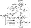
図5には、冷却運転に係る制御の処理手順を開示するフローチャートを示している。本フローチャートは、冷却用ECU100や空調ECU200に電源が投入されている状態で開始され、冷却用ECU100と空調ECU200とが互いに情報を通信することで、主に冷却用ECU100によって実行される。本フローチャートは、予め定めた時間間隔で繰り返し行われる。すなわち、本フローチャートが終了すると、所定時間経過後に再びステップ10以降の処理が実行されることになる。   FIG. 5 shows a flowchart disclosing a control processing procedure related to the cooling operation. This flowchart is started when the cooling ECU 100 and the air conditioning ECU 200 are powered on, and is mainly executed by the cooling ECU 100 when the cooling ECU 100 and the air conditioning ECU 200 communicate information with each other. This flowchart is repeatedly performed at predetermined time intervals. That is, when this flowchart is finished, the processing after step 10 is executed again after a predetermined time has elapsed.

本フローチャートが開始されると、まずステップ10で、車両が走行中であるか否かを判定する。ステップ10では、冷却用ECU100は、車両ECU300から取得した現在の車速情報に基いて当該判定を実行する。車速情報に基いてステップ10で車両が走行中であると判定すると、次にステップ20で、冷却水温センサ22によって検出された冷却水温Twが所定温度、例えば90℃を超えているか否かを判定する。   When this flowchart is started, it is first determined in step 10 whether or not the vehicle is running. In step 10, the cooling ECU 100 performs the determination based on the current vehicle speed information acquired from the vehicle ECU 300. If it is determined in step 10 that the vehicle is traveling based on the vehicle speed information, then in step 20, it is determined whether or not the coolant temperature Tw detected by the coolant temperature sensor 22 exceeds a predetermined temperature, for example, 90 ° C. To do.

ステップ20でTwが90℃を超えていないと判定すると、エンジン2の温度が高くないため、後方排気部を冷却する条件を満たしていない。そして、ステップ50に進み、第1ドア3を閉状態に制御する処理を実行し、本フローチャートを終了する。この場合、外気は外気導入通路31に流入せず、後方排気部の冷却は行われない(図2参照)。   If it is determined in step 20 that Tw does not exceed 90 ° C., the temperature of the engine 2 is not high, so the conditions for cooling the rear exhaust part are not satisfied. And it progresses to step 50, the process which controls the 1st door 3 to a closed state is performed, and this flowchart is complete | finished. In this case, the outside air does not flow into the outside air introduction passage 31, and the rear exhaust part is not cooled (see FIG. 2).

ステップ10でTwが90℃を超えていると判定すると、次のステップ30で排気マニホールド20の温度(排気温度Tex)が所定温度、例えば500℃を超えているか否かを判定する。ステップ30でTexが500℃を超えていないと判定すると、冷却水温Twは高くが、排気温度Texは高くないため、後方排気部を冷却する条件を満たしていない。この場合も、ステップ50に進み、第1ドア3を閉状態に制御する処理を実行し、後方排気部の冷却を行わずに本フローチャートを終了する。   If it is determined in step 10 that Tw exceeds 90 ° C., it is determined in next step 30 whether or not the temperature of the exhaust manifold 20 (exhaust temperature Tex) exceeds a predetermined temperature, for example, 500 ° C. If it is determined in step 30 that Tex does not exceed 500 ° C., the cooling water temperature Tw is high, but the exhaust temperature Tex is not high, so the conditions for cooling the rear exhaust part are not satisfied. Also in this case, the process proceeds to step 50, the process of controlling the first door 3 to the closed state is executed, and this flowchart is ended without cooling the rear exhaust part.

ステップ30でTexが500℃を超えていると判定すると、冷却水温Tw及び排気温度Texが高いため、後方排気部を冷却する条件を満たしている。この場合、ステップ40に進み、第1ドア3を開状態に制御する処理を実行し、後方排気部の冷却を行い、本フローチャートを終了する。このときの各部の状態及び外気の導入経路は、図1に図示するようになる。   If it is determined in step 30 that Tex exceeds 500 ° C., the cooling water temperature Tw and the exhaust temperature Tex are high, so the conditions for cooling the rear exhaust part are satisfied. In this case, it progresses to step 40, the process which controls the 1st door 3 to an open state is performed, a back exhaust part is cooled, and this flowchart is complete | finished. The state of each part and the outside air introduction path at this time are as shown in FIG.

走行中には、走行圧によって図1において破線A1で示すように、車両と地面との間、例えば、アンダーカバー45やフロアパネル46の近傍における空気の圧力が負圧エリアになる。一方、アンダーカバー45の前部と地面との間、フロントグリル41(車両前部)の近傍、エンジンフード40(またはボンネット)の後部近傍の空気の圧力は、図1において二点鎖線A2や二点鎖線A4で示すように、正圧エリアになる。なお、図1における破線A3のエリアは、車体表面における圧力分布が負圧のエリアになる。このため、車両前部、例えばフロントグリル41付近に空気は、フロントウインドシールド51側に向かって勢い良く流れるようになる。このような車両のCd値(抗力係数)に密接に関係する車体形状によって、車体表面におけるスムーズな空気流れを形成することができる。   During traveling, the air pressure in the vicinity of the under cover 45 and the floor panel 46 becomes a negative pressure area between the vehicle and the ground, for example, as indicated by a broken line A1 in FIG. On the other hand, the pressure of the air between the front part of the under cover 45 and the ground, in the vicinity of the front grille 41 (the front part of the vehicle) and in the vicinity of the rear part of the engine hood 40 (or the hood) is shown in FIG. As indicated by a dashed line A4, a positive pressure area is obtained. 1 is an area where the pressure distribution on the surface of the vehicle body is negative. For this reason, the air flows vigorously toward the front windshield 51 side near the front portion of the vehicle, for example, near the front grille 41. A smooth air flow on the surface of the vehicle body can be formed by the vehicle body shape closely related to the Cd value (drag coefficient) of the vehicle.

走行中に、エンジンルーム4の周囲における車体には、以上のような空気の圧力分布が形成されるため、エンジンルーム4上方のボンネット上をフロントウインドシールド51に向かう外気の気流が生じる。この気流の発生により、外気は、図1の実線矢印で示すように、車両前部から、ボンネット上、カウルへと流れ、第1ドア3によって開放された外気導入口30から外気導入通路31に流入するようになる。外気導入通路31に流入した外気は、外気導入通路31を下方に流れる際に、排気マニホールド20及び排気パイプ21の周囲を通過し、これらの外表面に接触することで後方排気部を吸熱して冷却する。吸熱した外気は、アンダーカバー45とフロアパネル46との隙間によって形成された外気排出用の開口から車外に排出されるため、後方排気部の熱は車外に放出される。   During traveling, the air pressure distribution as described above is formed in the vehicle body around the engine room 4, so that an outside air flow is generated on the hood above the engine room 4 toward the front windshield 51. Due to the generation of this air flow, the outside air flows from the front of the vehicle to the cowl on the hood as shown by the solid line arrow in FIG. 1, and enters the outside air introduction passage 31 from the outside air inlet 30 opened by the first door 3. Inflow. When the outside air flowing into the outside air introduction passage 31 flows downward through the outside air introduction passage 31, the outside air passes through the periphery of the exhaust manifold 20 and the exhaust pipe 21, and absorbs heat from the rear exhaust portion by contacting these outer surfaces. Cooling. The outside air that has absorbed heat is discharged to the outside of the vehicle through an outside air discharge opening formed by the gap between the under cover 45 and the floor panel 46, so that the heat of the rear exhaust is released to the outside of the vehicle.

車速情報に基いてステップ10で車両が停車中であると判定すると、次にステップ100で排気マニホールド20の温度(排気温度Tex)が所定温度、例えば500℃を超えているか否かを判定する。ステップ100でTexが500℃を超えていないと判定すると、停車中の排気温度Texは高くないため、後方排気部を冷却する条件を満たしていない。この場合も、ステップ50に進み、第1ドア3を閉状態に制御する処理を実行し、後方排気部の冷却を行わずに本フローチャートを終了する。   If it is determined in step 10 that the vehicle is stopped based on the vehicle speed information, it is next determined in step 100 whether or not the temperature of the exhaust manifold 20 (exhaust temperature Tex) exceeds a predetermined temperature, for example, 500 ° C. If it is determined in step 100 that Tex does not exceed 500 ° C., the exhaust temperature Tex while the vehicle is stopped is not high, and therefore the condition for cooling the rear exhaust part is not satisfied. Also in this case, the process proceeds to step 50, the process of controlling the first door 3 to the closed state is executed, and this flowchart is ended without cooling the rear exhaust part.

ステップ100でTexが500℃を超えていると判定すると、停車中の排気温度Texが高いため、後方排気部を冷却する条件を満たしている。さらにステップ110で車室内温度Trが外気温度Tamよりも高いか否かを判定する。ステップ110でTrがTamと同等またはTamよりも低温であると判定すると、外気よりも車室内5の空気を用いて後方排気部を冷却する方が効率的である。このため、ステップ120、ステップ130、ステップ140、ステップ150を実行して、車室内空気の導入による後方排気部の冷却を行い、本フローチャートを終了する。   If it is determined in step 100 that Tex exceeds 500 ° C., the exhaust temperature Tex while the vehicle is stopped is high, and therefore the condition for cooling the rear exhaust part is satisfied. Further, at step 110, it is determined whether or not the vehicle interior temperature Tr is higher than the outside air temperature Tam. If it is determined in step 110 that Tr is equal to Tam or a temperature lower than Tam, it is more efficient to cool the rear exhaust portion using the air in the vehicle compartment 5 than the outside air. Therefore, Step 120, Step 130, Step 140, and Step 150 are executed to cool the rear exhaust portion by introducing the vehicle interior air, and this flowchart is ended.

ステップ120では、第1ドア3を開状態に制御する。ステップ130では、空調装置1の空気取入れモードを、内気取入口13から車室内空気を取り入れる内気モードに設定するように制御する。ステップ140では、室内用ブロワ14を運転する。ステップ150では、第2ドア12を開状態に制御する。これらの処理により、室内用ブロワ14によって送風される空調空気の全部または一部は、空調風導入通路11を介してエンジンルーム4に吹き出され、後方排気部を冷却する。このときの各部の状態及び外気の導入経路は、図3に図示するようになる。   In step 120, the first door 3 is controlled to be opened. In step 130, the air intake mode of the air conditioner 1 is controlled to be set to the inside air mode for taking in the vehicle interior air from the inside air inlet 13. In step 140, the indoor blower 14 is operated. In step 150, the second door 12 is controlled to be opened. Through these processes, all or part of the conditioned air blown by the indoor blower 14 is blown out to the engine room 4 through the conditioned air introduction passage 11 to cool the rear exhaust part. The state of each part and the outside air introduction path at this time are as shown in FIG.

空調風導入通路11からエンジンルーム4に吹き出された空調空気は、後方排気部に接触した後、下方に流れて前述の排出用の開口から車外に排出されるので、後方排気部の熱は車外に放出される。また、上方の外気導入通路31は開放されているため、空調空気は、後方排気部に接触した後、温度上昇することで上方に流れて外気導入口30から車外に排出されうる。このように空調空気が上方に流れることにより、エンジン2の上部に位置する後方排気部、例えば排気マニホールド20に対する冷却性能を向上させることができる。   The conditioned air blown out from the conditioned air introduction passage 11 to the engine room 4 contacts the rear exhaust portion, and then flows downward and is discharged outside the vehicle through the aforementioned discharge opening. To be released. Further, since the upper outside air introduction passage 31 is open, the conditioned air can flow upward as the temperature rises after coming into contact with the rear exhaust part, and can be discharged out of the vehicle through the outside air introduction port 30. As the conditioned air flows in this way, the cooling performance for the rear exhaust part located at the top of the engine 2, for example, the exhaust manifold 20, can be improved.

ステップ110でTrがTamよりも高温であると判定すると、車室内温度よりも低温の外気で後方排気を冷却する方が効率的である。このため、次のステップ125で第1ドア3を開状態に制御する処理を実行して本フローチャートを終了する。したがって、車室内空気をエンジンルーム4に導入せず、外気導入通路31だけを開放することで、外気導入口30から流入する外気を用いて後方排気部の冷却を図る。特に、低温である外気は、下方に流れやすいため、外気導入口30から導入された後、下方に延びる外気導入通路31を流下するようになる。したがって、低温の外気は、外気導入通路31を上部から下部に流れ、車室内空気よりも後方排気部を効率的に冷却することができる。   If it is determined in step 110 that Tr is higher than Tam, it is more efficient to cool the rear exhaust with outside air that is cooler than the passenger compartment temperature. For this reason, the process which controls the 1st door 3 to an open state in the following step 125 is performed, and this flowchart is complete | finished. Accordingly, by not opening the vehicle interior air into the engine room 4 but only opening the outside air introduction passage 31, the outside exhaust air flowing from the outside air introduction port 30 is used to cool the rear exhaust part. In particular, since low temperature outside air tends to flow downward, it flows down through the outside air introduction passage 31 extending downward after being introduced from the outside air inlet 30. Therefore, the low temperature outside air flows from the upper part to the lower part in the outside air introduction passage 31 and can cool the rear exhaust part more efficiently than the air in the passenger compartment.

次に、第1実施形態の冷却装置がもたらす作用効果について説明する。冷却装置は、車両に搭載され、エンジン後部から後方に向けて排気が流れる排気通路を構成する後方排気部を有するエンジン2を備える。冷却装置は、車外とエンジンルーム4とを連絡する通路であり、車外から取り込まれる外気が後方排気部に向けて流入するようにエンジン2の後部寄りに設けられた外気導入通路31と、外気導入通路31を開状態と閉状態とに制御可能な第1ドア3と、を備える。   Next, the effect which the cooling device of 1st Embodiment brings is demonstrated. The cooling device includes an engine 2 that is mounted on a vehicle and has a rear exhaust portion that constitutes an exhaust passage through which exhaust flows from the rear of the engine toward the rear. The cooling device is a passage connecting the outside of the vehicle and the engine room 4, and an outside air introduction passage 31 provided near the rear of the engine 2 so that outside air taken in from the outside flows toward the rear exhaust portion, and outside air introduction A first door 3 capable of controlling the passage 31 in an open state and a closed state.

この構成によれば、エンジン2の後部寄りに設定された外気導入通路31に外気を導入することにより、外気流入時の通風抵抗を少なくしてスムーズにエンジンルーム4に取り入れることができる。さらに外気導入通路31に流入した外気は、後方排気部(排気マニホールド20や排気パイプ21)に向けて流れるため、冷却効果の高い新鮮な外気をエンジンルーム4の他の熱源から吸熱する前に後方排気部に接触させることができる。これにより、外気によって後方排気部を冷却する効果を格段に高めることが可能である。   According to this configuration, by introducing the outside air into the outside air introduction passage 31 set near the rear portion of the engine 2, the ventilation resistance when the outside air flows can be reduced and smoothly taken into the engine room 4. Furthermore, since the outside air that has flowed into the outside air introduction passage 31 flows toward the rear exhaust part (the exhaust manifold 20 and the exhaust pipe 21), the fresh outside air having a high cooling effect is rearward before absorbing heat from other heat sources in the engine room 4. The exhaust part can be contacted. Thereby, it is possible to remarkably enhance the effect of cooling the rear exhaust part by the outside air.

例えば、車両走行時には、第1ドア3を開状態にすることで、外気が車外から外気導入通路31を通って後方排気部に向けて流れ得るため、後方排気型のエンジン2の排気マニホールド20や排気パイプ21を冷却する能力を外気によって向上させることができる。このように、エンジン2の後部から排気が流れる後方排気部を効率的に排気できる冷却装置が得られる。   For example, when the vehicle is running, by opening the first door 3, the outside air can flow from outside the vehicle through the outside air introduction passage 31 toward the rear exhaust part, so that the exhaust manifold 20 of the rear exhaust type engine 2 or The ability to cool the exhaust pipe 21 can be improved by outside air. In this way, a cooling device that can efficiently exhaust the rear exhaust part through which exhaust flows from the rear part of the engine 2 is obtained.

また、外気導入通路31は、エンジン2よりも高い位置で外気を車外から取り入れる通路である。このような外気導入通路31の構成によれば、外気導入通路31が外気導入口30から下方に向かって延びることになるため、特に外気が低温である場合には、エンジンルーム4の空気に対して重い外気が外気導入通路31を流下しやすい。このため、外気はスムーズに下方に流下しながら排気マニホールド20や排気パイプ21に接触することができ、比較的速い流速の外気を後方排気部に接触させることが可能である。   The outside air introduction passage 31 is a passage for taking outside air from outside the vehicle at a position higher than the engine 2. According to such a configuration of the outside air introduction passage 31, the outside air introduction passage 31 extends downward from the outside air introduction port 30, and therefore, particularly when the outside air is at a low temperature, And heavy outside air easily flows down the outside air introduction passage 31. For this reason, the outside air can come into contact with the exhaust manifold 20 and the exhaust pipe 21 while smoothly flowing downward, and the outside air having a relatively high flow velocity can be brought into contact with the rear exhaust portion.

また、外気導入通路31は、エンジン2よりも後方の位置で外気を車外から取り入れる通路である。このような外気導入通路31の構成によれば、外気をエンジン2の前部よりも後部に積極的に接触させることができる。さらに後方排気部の一例である排気パイプ21は車両の後方へ延びるように設置されることが多いため、エンジン2よりも後方から導入された外気を排気パイプ21の広い範囲に接触させることができる。これにより、エンジン2から後方に延びる後方排気部を効率的に冷却することが可能である。   The outside air introduction passage 31 is a passage for taking in outside air from the outside of the vehicle at a position behind the engine 2. According to such a configuration of the outside air introduction passage 31, the outside air can be positively brought into contact with the rear portion of the engine 2 rather than the front portion. Further, since the exhaust pipe 21 which is an example of the rear exhaust part is often installed so as to extend rearward of the vehicle, the outside air introduced from the rear side of the engine 2 can be brought into contact with a wide range of the exhaust pipe 21. . Thereby, it is possible to efficiently cool the rear exhaust portion extending rearward from the engine 2.

また、外気導入通路31は、車両におけるエンジンフード40とフロントウインドシールド51との間に設けられた開口部である外気導入口30から外気を取り入れる通路である。このような外気導入通路31の構成によれば、前述したように走行中の車体周囲に形成される空気の圧力分布を利用した効率的な外気導入を実施することができる。また、空調装置1における外気の吸気口が形成される外板部等に外気導入口30を形成することができる。   The outside air introduction passage 31 is a passage for taking in outside air from the outside air introduction port 30 which is an opening provided between the engine hood 40 and the front windshield 51 in the vehicle. According to the configuration of the outside air introduction passage 31 as described above, it is possible to efficiently introduce outside air using the pressure distribution of the air formed around the traveling vehicle body as described above. Further, the outside air inlet 30 can be formed in an outer plate portion or the like where an outside air inlet is formed in the air conditioner 1.

また、外気導入通路31は、後方排気部の真上から外気を取り入れる通路である。このような外気導入通路31の構成によれば、外気導入通路31を外気導入口30から真下に向かって設けることができるため、外気の流速を重力を利用して加速させることが可能である。特に外気が低温である場合には、エンジンルーム4の空気に対して重い外気をさらに加速させやすい。このため、外気は外気導入通路31を加速しながら流下し、速い流速の外気を後方排気部に接触させることが可能である。   The outside air introduction passage 31 is a passage for taking in outside air from directly above the rear exhaust part. According to such a configuration of the outside air introduction passage 31, the outside air introduction passage 31 can be provided directly below the outside air introduction port 30, so that the flow rate of the outside air can be accelerated using gravity. In particular, when the outside air is at a low temperature, it is easy to further accelerate the outside air that is heavier than the air in the engine room 4. For this reason, the outside air can flow down while accelerating the outside air introduction passage 31, and the outside air having a high flow velocity can be brought into contact with the rear exhaust part.

車両の走行中に、第1ドア3は開状態に制御され、車外から取り入れられた外気は、外気導入通路31を下方に流れる。これによれば、外気導入口30を後方排気部よりも上方に位置させることができる。このため、前述したように走行中の車体周囲に形成される空気の圧力分布を利用して、外気を外気導入通路31に取り込むことができる。したがって、走行中の外気導入を効率的に実施でき、後方排気部により多くの外気を接触させることが可能になる。   While the vehicle is running, the first door 3 is controlled to be in an open state, and the outside air taken in from the outside of the vehicle flows downward through the outside air introduction passage 31. According to this, the outside air inlet 30 can be positioned above the rear exhaust part. For this reason, the outside air can be taken into the outside air introduction passage 31 using the pressure distribution of the air formed around the traveling vehicle body as described above. Therefore, it is possible to efficiently introduce the outside air during traveling and to bring more outside air into contact with the rear exhaust part.

また、冷却装置は、空調風導入通路11と、空調装置1の運転と第1ドア3の作動とを制御する制御装置を備える。空調風導入通路11は、車室内5を空調するための空調装置1において空調された空調空気を、エンジン2よりも後方から後方排気部に向けて流入させるように設けられている。制御装置は、停車中に、第1ドア3を開状態に制御するとともに、空調装置1において冷却された冷気を空調風導入通路11に流すように空調装置1の運転を制御する。   In addition, the cooling device includes an air conditioning air introduction passage 11, and a control device that controls the operation of the air conditioning device 1 and the operation of the first door 3. The conditioned air introduction passage 11 is provided so that conditioned air conditioned in the air conditioner 1 for air-conditioning the vehicle interior 5 flows from the rear of the engine 2 toward the rear exhaust part. The control device controls the operation of the air conditioner 1 so that the cold air cooled in the air conditioner 1 flows into the conditioned air introduction passage 11 while the first door 3 is controlled to be open while the vehicle is stopped.

これによれば、高速走行後に停車したときのように、走行時に形成される空気の圧力分布を利用できず、十分な量の外気をエンジンルーム4に取り込むことが困難な場合でも、後方排気部を効率的に冷却できる冷却装置を提供できる。また、空調空気の方が外気よりも低温であり、高い冷却効果が得られる場合にも、より効率的な冷却運転を実施できる。   According to this, even when it is difficult to take in a sufficient amount of outside air into the engine room 4 such as when stopping after high-speed traveling, it is difficult to use the pressure distribution of air formed during traveling. Can be efficiently cooled. Further, even when the conditioned air is at a lower temperature than the outside air and a high cooling effect is obtained, a more efficient cooling operation can be performed.

(第2実施形態)
第2実施形態では、第1実施形態で説明した冷却装置及び冷却運転に係る制御に対する他の実施形態について図6〜図8を参照して説明する。図6、図7において図1、図4等と同じ符号を付した構成は同様の構成であり、同様の作用効果を奏する。図8において図5と同じステップ番号を付したステップは同様の処理であり、同様の作用効果を奏する。以下に、第1実施形態とは異なる内容についてのみ説明する。
(Second Embodiment)
In the second embodiment, another embodiment for the control related to the cooling device and the cooling operation described in the first embodiment will be described with reference to FIGS. 6 and 7, the same reference numerals as those in FIGS. 1, 4, and the like are the same and have the same effects. In FIG. 8, steps denoted by the same step numbers as in FIG. 5 are the same processing and have the same effects. Only the contents different from the first embodiment will be described below.

図6に示すように、冷却装置は、第1ドア3と、車室内の空気をエンジンルーム4へ送風する送風装置61と、室内空気導入通路60を開閉可能な第3ドア62と、を関連させて制御することができる。図6には、冷却運転において、停車時に車室内空気の導入を行うときの各部の状態を示している。   As shown in FIG. 6, the cooling device relates the first door 3, a blower 61 that blows air in the vehicle compartment to the engine room 4, and a third door 62 that can open and close the indoor air introduction passage 60. Can be controlled. FIG. 6 shows the state of each part when air is introduced into the passenger compartment when the vehicle is stopped in the cooling operation.

車両には、車室内5とエンジンルーム4とを連絡するダクト6が設けられている。ダクト6は、室内空気導入通路60を構成する。ダクト6は、インストルメントパネル50の下部及びファイアウォール47を貫通するように設けられ、エンジンルーム4に位置する開口端部が排気マニホールド20や排気パイプ21に向かって開口している。したがって、室内空気導入通路60は、エンジン2よりも後方の位置から後方排気部に向けて車室内空気をエンジンルーム4に流入させる通路を構成する。   The vehicle is provided with a duct 6 that communicates between the vehicle compartment 5 and the engine room 4. The duct 6 constitutes an indoor air introduction passage 60. The duct 6 is provided so as to penetrate the lower part of the instrument panel 50 and the firewall 47, and an opening end portion located in the engine room 4 opens toward the exhaust manifold 20 and the exhaust pipe 21. Therefore, the indoor air introduction passage 60 constitutes a passage through which the vehicle interior air flows into the engine room 4 from a position behind the engine 2 toward the rear exhaust part.

ダクト6の内部には、室内空気導入通路60を開状態と閉状態とに制御可能な通路開閉装置の一例である第3ドア62が設けられている。第3ドア62は、冷却運転のために備えられた専用の装置であり、開状態に制御された場合は車室内空気がエンジンルーム4に流入することを許容する。第3ドア62は、閉状態に制御された場合は室内空気導入通路60における空気の流通を阻止し、エンジンルーム4への車室内空気の流入を禁止する。ダクト6の内部には、車室内空気をエンジンルーム4に向けて送風する送風装置61が設けられている。送風装置61は、冷却運転のために備えられた専用の装置であり、第3ドア62が開状態に制御された場合に車室内空気をエンジンルーム4に流入させることができる。   Inside the duct 6 is provided a third door 62 which is an example of a passage opening / closing device capable of controlling the indoor air introduction passage 60 in an open state and a closed state. The third door 62 is a dedicated device provided for the cooling operation, and allows the air in the passenger compartment to flow into the engine room 4 when controlled to the open state. When the third door 62 is controlled to be closed, the third door 62 prevents air from flowing through the indoor air introduction passage 60 and prohibits inflow of vehicle interior air into the engine room 4. Inside the duct 6 is provided a blower 61 that blows vehicle interior air toward the engine room 4. The blower device 61 is a dedicated device provided for the cooling operation, and allows the air in the vehicle compartment to flow into the engine room 4 when the third door 62 is controlled to be in the open state.

第3ドア62及び送風装置61の作動は、冷却用ECU100により制御される。冷却用ECU100は、第3ドア62の回転軸部を駆動するモータに印加する電圧値を制御することにより、第3ドア62のドア本体の回転位置を制御して、室内空気導入通路60の開度を制御する。したがって、冷却用ECU100は、室内空気導入通路60に流入する室内空気の風量を可変することができる。後方排気部を冷却可能な能力は、冷却用ECU100による第3ドア62の開度制御と送風装置61による風量制御とによって調整されることになる。   The operation of the third door 62 and the blower 61 is controlled by the cooling ECU 100. The cooling ECU 100 controls the rotational position of the door body of the third door 62 by controlling the voltage value applied to the motor that drives the rotating shaft of the third door 62, thereby opening the indoor air introduction passage 60. Control the degree. Therefore, the cooling ECU 100 can vary the air volume of the room air flowing into the room air introduction passage 60. The ability to cool the rear exhaust part is adjusted by the opening degree control of the third door 62 by the cooling ECU 100 and the air volume control by the blower 61.

次に、冷却装置による後方排気部の冷却運転と、冷却運転に関連させる送風装置61及び第3ドア62の運転とについて図6、図8を参照して説明する。   Next, the cooling operation of the rear exhaust unit by the cooling device and the operation of the blower 61 and the third door 62 related to the cooling operation will be described with reference to FIGS. 6 and 8.

図8には、冷却運転に係る制御の処理手順を開示するフローチャートを示している。本フローチャートにおける、ステップ10、20、3040、50、100、110は、第1実施形態において説明した処理と同様である。   FIG. 8 shows a flowchart disclosing the control processing procedure related to the cooling operation. Steps 10, 20, 3040, 50, 100, and 110 in this flowchart are the same as the processes described in the first embodiment.

ステップ100でTexが500℃を超えていると判定すると、次にステップ110で車室内温度Trが外気温度Tamよりも高いか否かを判定する。ステップ110でTrがTamと同等またはTamよりも低温であると判定すると、外気よりも車室内5の空気を用いて後方排気部を冷却する方が効率的である。このため、ステップ200、ステップ210、ステップ220を実行して、車室内空気の導入による後方排気部の冷却を行い、本フローチャートを終了する。   If it is determined in step 100 that Tex exceeds 500 ° C., it is next determined in step 110 whether the vehicle interior temperature Tr is higher than the outside air temperature Tam. If it is determined in step 110 that Tr is equal to Tam or a temperature lower than Tam, it is more efficient to cool the rear exhaust portion using the air in the vehicle compartment 5 than the outside air. Therefore, Step 200, Step 210, and Step 220 are executed to cool the rear exhaust portion by introducing the vehicle interior air, and this flowchart is finished.

ステップ200では、第1ドア3を開状態に制御する。ステップ210では、送風装置61を運転する。ステップ220では、第3ドア62を開状態に制御する。これらの処理により、送風装置61によって送風される車室内空気の全部は、室内空気導入通路60を介してエンジンルーム4に吹き出され、後方排気部を冷却する。このときの各部の状態及び外気の導入経路は、図6に図示するようになる。   In step 200, the first door 3 is controlled to be opened. In step 210, the blower 61 is operated. In step 220, the third door 62 is controlled to be opened. Through these processes, all of the passenger compartment air blown by the blower 61 is blown out to the engine room 4 via the indoor air introduction passage 60 to cool the rear exhaust part. The state of each part and the outside air introduction path at this time are as shown in FIG.

室内空気導入通路60からエンジンルーム4に吹き出された車室内空気は、後方排気部に接触した後、下方に流れて前述の排出用の開口から車外に排出されるので、後方排気部の熱は車外に放出される。また、上方の外気導入通路31は開放されているため、車室内空気は、後方排気部に接触した後、温度上昇することで上方に流れて外気導入口30から車外に排出されうる。   After the vehicle interior air blown out from the indoor air introduction passage 60 to the engine room 4 contacts the rear exhaust portion, the vehicle interior air flows downward and is discharged out of the vehicle through the aforementioned discharge opening. Released outside the car. Further, since the upper outside air introduction passage 31 is open, the vehicle interior air can flow upward as the temperature rises after coming into contact with the rear exhaust portion, and can be discharged from the outside air introduction port 30 to the outside.

ステップ110でTrがTamよりも高温であると判定すると、次のステップ205で第1ドア3を開状態に制御する処理を実行して本フローチャートを終了する。したがって、前述の第1実施形態における説明と同様の理由から、低温の外気は、外気導入通路31を上部から下部に流れ、車室内空気よりも後方排気部を効率的に冷却することができる。また、上方の外気導入通路31は開放されているため、車室内空気は、後方排気部に接触した後、温度上昇することで上方に流れて外気導入口30から車外に排出されうる。このように車室内空気が上方に流れることにより、エンジン2の上部に位置する後方排気部、例えば排気マニホールド20に対する冷却性能を向上させることができる。   If it is determined in step 110 that Tr is higher than Tam, in the next step 205, processing for controlling the first door 3 to the open state is executed, and this flowchart is ended. Therefore, for the same reason as described in the first embodiment, the low-temperature outside air can flow from the top to the bottom in the outside air introduction passage 31 and cool the rear exhaust part more efficiently than the air in the passenger compartment. Further, since the upper outside air introduction passage 31 is open, the vehicle interior air can flow upward as the temperature rises after coming into contact with the rear exhaust portion, and can be discharged from the outside air introduction port 30 to the outside. As described above, the vehicle interior air flows upward, so that it is possible to improve the cooling performance with respect to the rear exhaust part, for example, the exhaust manifold 20, located at the upper part of the engine 2.

次に、第2実施形態の冷却装置がもたらす作用効果について説明する。冷却装置は、車室内空気をエンジン2よりも後方から後方排気部に向けて流入させる室内空気導入通路60と、室内空気導入通路60に車室内の空気を流す送風装置61と、第1ドア3の作動と送風装置61の運転とを制御する制御装置と、を備える。制御装置は、停車中に、第1ドア3を開状態に制御するとともに、車室内空気を室内空気導入通路60に流すように送風装置61の運転を制御する。   Next, the effect which the cooling device of 2nd Embodiment brings is demonstrated. The cooling device includes an indoor air introduction passage 60 that allows the vehicle interior air to flow from the rear toward the rear exhaust portion of the engine 2, a blower device 61 that causes the air in the vehicle interior to flow through the indoor air introduction passage 60, and the first door 3. And a control device for controlling the operation of the blower 61. The control device controls the operation of the blower 61 so that the vehicle interior air flows through the indoor air introduction passage 60 while the first door 3 is controlled to be open while the vehicle is stopped.

これによれば、高速走行後の停車時(デッドソーク時)のように、走行時に形成される空気の圧力分布を利用できず、十分な量の外気をエンジンルーム4に取り込むことが困難な場合でも、後方排気部を効率的に冷却可能な冷却装置を提供できる。また、車室内空気の方が外気よりも低温であり、高い冷却効果が得られる場合にも、より効率的な冷却運転を実施できる。   According to this, even when it is difficult to take in a sufficient amount of outside air into the engine room 4, such as when stopping after high-speed driving (at the time of dead soak), the pressure distribution of air formed during driving cannot be used. A cooling device capable of efficiently cooling the rear exhaust part can be provided. Further, when the passenger compartment air is at a lower temperature than the outside air and a high cooling effect is obtained, a more efficient cooling operation can be performed.

また、制御装置は、停車中に、外気の温度が車室内空気の温度よりも低い場合には、第1ドア3を開状態に制御し、送風装置61を停止するように制御する。これによれば、外気よりも高温である車室内空気をエンジンルーム4に導入することなく、外気を積極的に導入することで、効率的な冷却運転を実現できる。   In addition, when the temperature of the outside air is lower than the temperature of the vehicle interior air while the vehicle is stopped, the control device controls the first door 3 to be in an open state and controls the blower 61 to stop. According to this, an efficient cooling operation can be realized by positively introducing the outside air without introducing the vehicle interior air having a temperature higher than that of the outside air into the engine room 4.

さらに、外気導入口30がエンジン2よりも高い位置に設けられている場合や、外気導入通路31が後方排気部の真上から外気を取り入れる場合や、外気導入口30がカウルに設けられている場合には、以下のような効果が得られる。すなわち、低温である外気は、外気導入通路31を上部から下部に流れるため、車室内空気を導入する場合に比べて後方排気部を効率的に冷却でき、さらに送風するための電力等を必要としない点でも省エネルギ化も図れる。   Furthermore, when the outside air introduction port 30 is provided at a position higher than the engine 2, when the outside air introduction passage 31 takes in outside air from directly above the rear exhaust part, or when the outside air introduction port 30 is provided in the cowl. In this case, the following effects can be obtained. That is, since the outside air having a low temperature flows from the upper part to the lower part of the outside air introduction passage 31, the rear exhaust part can be cooled more efficiently than the case where the vehicle interior air is introduced, and electric power for blowing air is required. This also saves energy.

(他の実施形態)
以上、開示された発明の好ましい実施形態について説明したが、開示された発明は上述した実施形態に何ら制限されることなく、種々変形して実施することが可能である。前述の実施形態の構造は、あくまで例示であって、開示された発明の技術的範囲はこれらの記載の範囲に限定されるものではない。開示された発明の技術的範囲は、特許請求の範囲の記載によって示され、さらに特許請求の範囲の記載と均等の意味及び範囲内での全ての変更を含むものである。
(Other embodiments)
The preferred embodiments of the disclosed invention have been described above, but the disclosed invention is not limited to the above-described embodiments, and various modifications can be made. The structure of the above-described embodiment is merely an example, and the technical scope of the disclosed invention is not limited to the scope of these descriptions. The technical scope of the disclosed invention is indicated by the description of the scope of claims, and further includes all modifications within the meaning and scope equivalent to the description of the scope of claims.

前述の実施形態においてエンジン2は、後部から排気が流出する排気マニホールド20を有するが、さらに、前部から排気が流出する排気マニホールドを有するように構成してもよい。つまり、本発明に係る冷却装置が冷却する後方排気部を有するエンジンは、後部以外に前部からも排気が排出される構成を備えるものでもよい。   In the above-described embodiment, the engine 2 has the exhaust manifold 20 from which exhaust flows out from the rear, but may further be configured to have an exhaust manifold from which exhaust flows out from the front. That is, the engine having the rear exhaust part cooled by the cooling device according to the present invention may have a configuration in which exhaust gas is discharged from the front part in addition to the rear part.

前述の実施形態においては、第1ドア3の動作を制御する冷却用ECU100と空調装置1の運転を制御する空調ECU200とが連携して、冷却装置の作動が制御されるように構成されている。冷却装置の制御は、このように、互いに通信する複数のECUによって構成される形態に限定されるものではない。例えば、冷却装置の作動は、第1ドア3と空調装置1との両方についてこれらの作動を制御する単一の制御装置、すなわちシステム制御装置によって制御される構成でもよい。また、単一の制御装置は、空調ECU200であってもよい。   In the above-described embodiment, the cooling ECU 100 that controls the operation of the first door 3 and the air conditioning ECU 200 that controls the operation of the air conditioner 1 cooperate to control the operation of the cooling device. . Control of a cooling device is not limited to the form comprised by several ECUs which communicate with each other in this way. For example, the operation of the cooling device may be controlled by a single control device that controls the operation of both the first door 3 and the air conditioner 1, that is, the system control device. The single control device may be the air conditioning ECU 200.

前述の実施形態における第1ドア3は、ドア本体が回転駆動されて、開状態と閉状態とに切り替え制御される通路開閉装置であるが、このような駆動形態に限定されるものではない。例えば、第1ドア3は、ドア本体がスライドすることにより外気導入通路31を開閉する形態に構成される装置でもよい。   The first door 3 in the above-described embodiment is a passage opening / closing device that is controlled to be switched between an open state and a closed state when the door body is rotationally driven, but is not limited to such a drive mode. For example, the first door 3 may be a device configured to open and close the outside air introduction passage 31 by sliding the door body.

前述の実施形態においては、冷却水温Twが車両ECU300を介して空調ECU200に入力されるとしているが、車両ECU300を介さずに直接空調ECU200に入力されるように構成してもよい。   In the above-described embodiment, the cooling water temperature Tw is input to the air conditioning ECU 200 via the vehicle ECU 300. However, the cooling water temperature Tw may be directly input to the air conditioning ECU 200 without passing through the vehicle ECU 300.

2…エンジン
3…第1ドア(通路開閉装置)
4…エンジンルーム
20…排気マニホールド(後方排気部)
21…排気パイプ(後方排気部)
31…外気導入通路
2 ... Engine 3 ... First door (passage opening / closing device)
4 ... Engine room 20 ... Exhaust manifold (rear exhaust part)
21 ... Exhaust pipe (rear exhaust part)
31 ... outside air introduction passage

Claims (8)

車両に搭載され、エンジン後部から後方に向けて排気が流れる排気通路を構成する後方排気部(20、21)を有するエンジン(2)と、
車外と前記エンジンが設置されるエンジンルーム(4)とを連絡する通路であって、前記車外から取り込まれる外気が前記後方排気部に向けて流入するように、前記エンジンの後部寄りに設けられた外気導入通路(31)と、
前記外気導入通路において空気の流通を許容する開状態と阻止する閉状態とに制御可能な通路開閉装置(3)と、
車室内を空調するための車両用空調装置(1)において空調された空調空気を、前記エンジンよりも後方から前記後方排気部に向けて流入させるように設けられた空調風導入通路(11)と、
前記車両用空調装置の運転と前記通路開閉装置の作動とを制御する制御装置(100)と、
を備え
前記制御装置は、停車中に、前記通路開閉装置を前記開状態に制御するとともに、前記車両用空調装置において冷却された冷気を前記空調風導入通路に流すように前記車両用空調装置の運転を制御することを特徴とする冷却装置。
An engine (2) mounted on a vehicle and having a rear exhaust part (20, 21) constituting an exhaust passage through which exhaust flows from the rear part of the engine toward the rear;
A passage connecting the outside of the vehicle and the engine room (4) in which the engine is installed, provided near the rear of the engine so that outside air taken in from the outside flows into the rear exhaust portion. An outside air introduction passage (31);
A passage opening and closing device (3) that is controllable to an open state that allows air flow in the outside air introduction passage and a closed state that blocks air flow;
A conditioned air introduction passage (11) provided so as to allow the conditioned air conditioned in the vehicle air conditioner (1) for air-conditioning the vehicle interior to flow from the rear toward the rear exhaust part from the engine; ,
A control device (100) for controlling the operation of the vehicle air conditioner and the operation of the passage opening and closing device;
Equipped with a,
The control device controls the passage opening and closing device to the open state while the vehicle is stopped, and operates the vehicle air conditioning device so that the cool air cooled in the vehicle air conditioning device flows through the conditioned air introduction passage. A cooling device characterized by controlling .
車両に搭載され、エンジン後部から後方に向けて排気が流れる排気通路を構成する後方排気部(20、21)を有するエンジン(2)と、
車外と前記エンジンが設置されるエンジンルーム(4)とを連絡する通路であって、前記車外から取り込まれる外気が前記後方排気部に向けて流入するように、前記エンジンの後部寄りに設けられた外気導入通路(31)と、
前記外気導入通路において空気の流通を許容する開状態と阻止する閉状態とに制御可能な通路開閉装置(3)と、
車室内の空気を、前記エンジンよりも後方から前記後方排気部に向けて流入させるように設けられた室内空気導入通路(11、60)と、
前記室内空気導入通路に車室内の空気を流す送風装置(61)と、
前記通路開閉装置の作動と前記送風装置の運転とを制御する制御装置(100)と、
を備え、
前記制御装置は、停車中に、前記通路開閉装置を前記開状態に制御するとともに、車室内の空気を前記室内空気導入通路に流すように前記送風装置の運転を制御することを特徴とする冷却装置。
An engine (2) mounted on a vehicle and having a rear exhaust part (20, 21) constituting an exhaust passage through which exhaust flows from the rear part of the engine toward the rear;
A passage connecting the outside of the vehicle and the engine room (4) in which the engine is installed, provided near the rear of the engine so that outside air taken in from the outside flows into the rear exhaust portion. An outside air introduction passage (31);
A passage opening and closing device (3) that is controllable to an open state that allows air flow in the outside air introduction passage and a closed state that blocks air flow;
Indoor air introduction passages (11, 60) provided so as to allow air in the vehicle compartment to flow from the rear toward the rear exhaust part from the engine;
A blower (61) for flowing the air in the vehicle interior to the indoor air introduction passage;
A control device (100) for controlling the operation of the passage opening and closing device and the operation of the blower;
With
The control device controls the operation of the blower so as to flow the air in the passenger compartment to the indoor air introduction passage while controlling the passage opening and closing device to the open state while the vehicle is stopped. apparatus.
前記制御装置は、停車中に、外気の温度が車室内の空気の温度よりも低い場合には、前記通路開閉装置を前記開状態に制御し、前記送風装置を停止するように制御することを特徴とする請求項2に記載の冷却装置。 When the outside air temperature is lower than the temperature of the air in the passenger compartment while the vehicle is stopped, the control device controls the passage opening / closing device to the open state and controls the air blower to stop. The cooling device according to claim 2, wherein 前記外気導入通路は、前記エンジンよりも高い位置で前記外気を前記車外から取り入れる通路であることを特徴とする請求項1から請求項3のいずれか一項に記載の冷却装置。 The cooling device according to any one of claims 1 to 3, wherein the outside air introduction passage is a passage for taking in the outside air from the outside of the vehicle at a position higher than the engine . 前記外気導入通路は、前記エンジンよりも後方の位置で前記外気を前記車外から取り入れる通路であることを特徴とする請求項4に記載の冷却装置。 The cooling device according to claim 4 , wherein the outside air introduction passage is a passage for taking in the outside air from the outside of the vehicle at a position behind the engine . 前記外気導入通路は、前記車両におけるエンジンフード(40)とフロントウインドシールド(51)との間に設けられた開口部(30)から前記外気を取り入れる通路であることを特徴とする請求項5に記載の冷却装置。 6. The outside air introduction passage is a passage for taking in the outside air from an opening (30) provided between an engine hood (40) and a front windshield (51) in the vehicle. The cooling device as described. 前記外気導入通路は、前記後方排気部の真上から前記外気を取り入れる通路であることを特徴とする請求項5または請求項6に記載の冷却装置。 The cooling device according to claim 5 or 6, wherein the outside air introduction passage is a passage for taking in the outside air from directly above the rear exhaust portion . 前記車両の走行中に、前記通路開閉装置は前記開状態に制御され、前記車外から取り入れられた前記外気は、前記外気導入通路を下方に流れることを特徴とする請求項5から請求項7のいずれか一項に記載の冷却装置。 8. The passage opening and closing device is controlled to be in the open state while the vehicle is running, and the outside air taken from outside the vehicle flows downward in the outside air introduction passage . The cooling device according to any one of the above.
JP2014191045A 2014-09-19 2014-09-19 Cooling system Active JP6319009B2 (en)

Priority Applications (3)

Application Number Priority Date Filing Date Title
JP2014191045A JP6319009B2 (en) 2014-09-19 2014-09-19 Cooling system
DE112015004248.2T DE112015004248B4 (en) 2014-09-19 2015-08-25 Cooling devices
PCT/JP2015/004253 WO2016042709A1 (en) 2014-09-19 2015-08-25 Cooling apparatus

Applications Claiming Priority (1)

Application Number Priority Date Filing Date Title
JP2014191045A JP6319009B2 (en) 2014-09-19 2014-09-19 Cooling system

Publications (3)

Publication Number Publication Date
JP2016060410A JP2016060410A (en) 2016-04-25
JP2016060410A5 JP2016060410A5 (en) 2016-09-01
JP6319009B2 true JP6319009B2 (en) 2018-05-09

Family

ID=55532768

Family Applications (1)

Application Number Title Priority Date Filing Date
JP2014191045A Active JP6319009B2 (en) 2014-09-19 2014-09-19 Cooling system

Country Status (3)

Country Link
JP (1) JP6319009B2 (en)
DE (1) DE112015004248B4 (en)
WO (1) WO2016042709A1 (en)

Families Citing this family (6)

* Cited by examiner, † Cited by third party
Publication number Priority date Publication date Assignee Title
US9879591B2 (en) 2015-02-20 2018-01-30 Pratt & Whitney Canada Corp. Engine intake assembly with selector valve
US9896998B2 (en) 2015-02-20 2018-02-20 Pratt & Whitney Canada Corp. Compound engine assembly with modulated flow
US9932892B2 (en) 2015-02-20 2018-04-03 Pratt & Whitney Canada Corp. Compound engine assembly with coaxial compressor and offset turbine section
US9797297B2 (en) 2015-02-20 2017-10-24 Pratt & Whitney Canada Corp. Compound engine assembly with common inlet
JP6493554B2 (en) 2015-11-03 2019-04-03 株式会社デンソー Airflow control system
DE112016005531T5 (en) 2015-12-02 2018-08-30 Denso Corporation Airflow control system

Family Cites Families (10)

* Cited by examiner, † Cited by third party
Publication number Priority date Publication date Assignee Title
JPS6112924U (en) * 1984-06-28 1986-01-25 富士重工業株式会社 Vehicle exhaust system cooling and heat shielding device
JPS61108610U (en) * 1984-12-21 1986-07-10
DE4127634C2 (en) 1991-08-21 1994-03-10 Bayerische Motoren Werke Ag Exhaust system with a covered front pipe
JPH05169986A (en) 1991-12-24 1993-07-09 Nissan Motor Co Ltd Engine room structure
DE19948148B4 (en) 1999-10-07 2009-09-17 Volkswagen Ag Motor vehicle with an internal combustion engine
DE10133422A1 (en) 2001-07-10 2003-01-30 Bayerische Motoren Werke Ag Device for adjusting the temperature of exhaust gases
DE10222320A1 (en) 2002-05-18 2003-12-04 Bayerische Motoren Werke Ag Actuator for an air control valve
AT501385B1 (en) 2003-04-10 2007-12-15 Avl List Gmbh INTERNAL COMBUSTION ENGINE WITH AN EXHAUST SYSTEM
DE10328991A1 (en) 2003-06-27 2005-02-17 Bayerische Motoren Werke Ag Exhaust gas unit for an internal combustion engine has a catalytic exhaust gas cleaning device, an air channel with a controlled flow rate and ribs stretching into the air channel
DE102008018567A1 (en) 2008-04-12 2009-10-15 Daimler Ag Aerator for passenger car, has air inlet provided in area of rear upper end of engine compartment, in area of front hood covering compartment and in area of disk root, where air channel extends downward from rear upper end of compartment

Also Published As

Publication number Publication date
JP2016060410A (en) 2016-04-25
DE112015004248B4 (en) 2021-08-05
WO2016042709A1 (en) 2016-03-24
DE112015004248T5 (en) 2017-06-08

Similar Documents

Publication Publication Date Title
JP6319009B2 (en) Cooling system
US8241097B2 (en) Environmental control system and method for a battery in a vehicle
JP3125198B2 (en) Battery temperature control device for electric vehicle
US20150380785A1 (en) Temperature regulation device
JP4710616B2 (en) Vehicle battery cooling system
JP2009252688A (en) Temperature control system of storage battery for vehicle
JP2008141945A (en) Cooling device for electricity storage mechanism
US11161390B2 (en) Air flow control system
KR20120023409A (en) Air-conditioning method for electric vehicle
JP2013180614A (en) Vehicle battery temperature control structure
JP2007137127A (en) Battery cooling and air conditioning device for vehicle
JP6634957B2 (en) Blower for battery cooling
JP2014189077A (en) Hybrid vehicle
JP2008247341A (en) Cooling device of in-vehicle heating element
JP4626506B2 (en) Cooling control device for electric equipment mounted on vehicle
JP4239698B2 (en) Air conditioner for vehicles
JP2007153054A (en) Cooling device of electric equipment mounted on vehicle
JP2005088752A (en) Driving battery cooling control device
JP2009274573A (en) Air conditioning device for vehicle
JP5780176B2 (en) Ventilation structure for vehicles
JP2006248386A (en) Vehicular air conditioner
JP2005041356A (en) Ventilation system for vehicle
KR101438094B1 (en) Cooling and heating system for using battery cooling system of air conditioner of hybrid electric vehicles
JP2010111168A (en) Exhaust heat collecting system for vehicle
JP6079564B2 (en) Air conditioning control device for vehicles

Legal Events

Date Code Title Description
A521 Written amendment

Free format text: JAPANESE INTERMEDIATE CODE: A523

Effective date: 20160718

A621 Written request for application examination

Free format text: JAPANESE INTERMEDIATE CODE: A621

Effective date: 20170322

TRDD Decision of grant or rejection written
A01 Written decision to grant a patent or to grant a registration (utility model)

Free format text: JAPANESE INTERMEDIATE CODE: A01

Effective date: 20180306

A61 First payment of annual fees (during grant procedure)

Free format text: JAPANESE INTERMEDIATE CODE: A61

Effective date: 20180319

R151 Written notification of patent or utility model registration

Ref document number: 6319009

Country of ref document: JP

Free format text: JAPANESE INTERMEDIATE CODE: R151