JP6317543B2 - Reflective sensor for automatic door - Google Patents
Reflective sensor for automatic door Download PDFInfo
- Publication number
- JP6317543B2 JP6317543B2 JP2013012968A JP2013012968A JP6317543B2 JP 6317543 B2 JP6317543 B2 JP 6317543B2 JP 2013012968 A JP2013012968 A JP 2013012968A JP 2013012968 A JP2013012968 A JP 2013012968A JP 6317543 B2 JP6317543 B2 JP 6317543B2
- Authority
- JP
- Japan
- Prior art keywords
- light
- intersection
- lens
- elements
- light emitting
- Prior art date
- Legal status (The legal status is an assumption and is not a legal conclusion. Google has not performed a legal analysis and makes no representation as to the accuracy of the status listed.)
- Active
Links
Images


Landscapes
- Geophysics And Detection Of Objects (AREA)
- Optical Elements Other Than Lenses (AREA)
- Lenses (AREA)
- Non-Portable Lighting Devices Or Systems Thereof (AREA)
Description
本発明は、発光素子からの照射光を複数の光線(スポット光)に分割する自動ドア用反射式センサに好適な分割レンズに関し、さらに詳しく言えば、分割レンズのレンズ素子間の境界面によって生ずる迷光を低減させる技術に関するものである。 The present invention relates to a split lens suitable for a reflective sensor for an automatic door that splits light emitted from a light emitting element into a plurality of light beams (spot light). More specifically, the split lens is generated by a boundary surface between lens elements of the split lens. The present invention relates to a technique for reducing stray light.
自動ドア用反射式センサにおいては、発光素子(赤外線発光素子)より自動ドア近傍の床面に向けて検出光として赤外光を照射するにあたって、1つの発光素子から複数のスポット光を得るため分割レンズを備えている(例えば、特許文献1参照)。 In the reflective sensor for automatic doors, when emitting infrared light as detection light from the light emitting element (infrared light emitting element) toward the floor near the automatic door, it is divided to obtain a plurality of spot lights from one light emitting element. A lens is provided (see, for example, Patent Document 1).
分割レンズは、複数の凸レンズ素子を一体的に接合してなるレンズで、一例として、2分割レンズと3素子の組み合わせで6つのスポット光が得られ、3分割レンズと4素子の組み合わせでは12のスポット光が得られる。 The split lens is a lens formed by integrally joining a plurality of convex lens elements. As an example, six spot lights can be obtained by combining two split lenses and three elements, and twelve spots can be obtained by combining three split lenses and four elements. Spot light is obtained.
しかしながら、分割レンズには迷光が発生するという固有の問題がある。迷光は、隣接する凸レンズ素子間の境界面(接合面)によって生ずる。この迷光は、各凸レンズ素子の中心を通る本来のスポット光の間に現れるため、誤検知等の不具合の要因となる。 However, the split lens has an inherent problem that stray light is generated. Stray light is generated by a boundary surface (joint surface) between adjacent convex lens elements. Since this stray light appears between the original spot lights passing through the centers of the convex lens elements, it causes a problem such as false detection.
図7に示す2素子,2分割レンズの組み合わせを例にして、迷光の発生メカニズムと、従来の迷光対策について説明する。 A stray light generation mechanism and a conventional countermeasure against stray light will be described with reference to an example of a combination of two elements and two-divided lenses shown in FIG.
2分割レンズ1は、中心Oaを有する凸レンズ素子1aと、中心Obを有する凸レンズ素子1bとを一体的に含み、その境界面をXとする。通常、この種の分割レンズは、金型内で例えばアクリル樹脂等により一体成型されるため、境界面Xは実際には存在しない仮想の境界面である。
The two-divided
自動ドア用反射式センサにおいて、素子L1,L2には、通常、赤外線発光素子が用いられ、境界面Xを中心として左右対称に配置される。 In the reflective sensor for automatic doors, infrared light emitting elements are usually used as the elements L1 and L2 and are arranged symmetrically about the boundary surface X.
素子L1から照射される赤外光のうち、各レンズ中心Oa,Obを通る光が床面に照射すべき本来のスポット光SP1a,SP1bであるが、境界面Xを横切る光によって領域F1の部分に迷光が発生する。 Of the infrared light irradiated from the element L1, the light passing through the lens centers Oa and Ob is the original spot light SP1a and SP1b to be irradiated on the floor surface. Stray light is generated.
同様に、素子L2から照射される赤外光のうち、各レンズ中心Oa,Obを通る光が床面に照射すべき本来のスポット光SP2a,SP2bであるが、境界面Xを横切る光によって領域F2の部分に迷光が発生する。 Similarly, of the infrared light irradiated from the element L2, the light passing through the lens centers Oa and Ob is the original spot light SP2a and SP2b to be irradiated on the floor surface. Stray light is generated in the portion F2.
分割レンズの場合、このような迷光が必ず発生する。そこで、従来においては、分割レンズ1の前面(光出射面側)に透明なレンズカバー2を配置し、迷光が現れる領域F1,F2に対応する部分に遮光テープ3,3を貼り付けて迷光を遮光するようにしている。
In the case of a split lens, such stray light always occurs. Therefore, conventionally, a transparent lens cover 2 is disposed on the front surface (light emitting surface side) of the
しかしながら、この遮光方法によると、遮光テープ3によって正規のスポット光の一部までが遮光され感度が低下するおそれがあるため、好ましくない。
However, this light shielding method is not preferable because a part of the regular spot light is shielded by the
また、分割レンズ1とレンズカバー2との距離が離れると、必然的に迷光の遮光エリアも大きくなるため、遮光テープ3の位置合わせや大きさ等の調整にかなりの時間の手間がかかる。
Further, if the distance between the divided
さらには、レンズカバー2と遮光テープ3を必要とするため、その分、コストアップになるばかりでなく、長期間にわたって使用した場合、遮光テープが剥がれたりするおそれもあり、信頼性の点でも問題がある。
Furthermore, since the lens cover 2 and the
そこで、本発明の課題は、分割レンズ固有の問題である迷光を簡単な方法によって大幅に低減することにある。 Therefore, an object of the present invention is to significantly reduce stray light, which is a problem inherent to the split lens, by a simple method.
上記課題を解決するため、本発明は、複数の凸レンズ素子を一体的に接合した分割レンズと、複数の発光素子とを含み、隣接する上記発光素子が上記分割レンズの光入射面側で上記凸レンズ素子間の境界面を含む面を中心としてほぼ左右対称に配置されており、上記各発光素子から照射された光が上記各凸レンズ素子ごとにその中心を通る複数の光線に分割される自動ドア用反射式センサにおいて、
上記分割レンズの光入射面および/または光出射面自体に、上記発光素子から照射される光のうち隣接する上記凸レンズ素子間の境界面を横切る光による迷光を低減させる遮光性マスクを備えており、
上記光入射面と上記境界面との交点をA,上記光出射面と上記境界面との交点をB,上記発光素子と上記交点Aとを含む第1仮想直線と上記光出射面との交点をS,上記発光素子と上記交点Bとを含む第2仮想直線と上記光入射面との交点をTとして、
上記遮光性マスクは、上記光出射面側の上記交点Sと交点Bとの間および/または上記光入射面側の上記交点Tと交点Aとの間に設けられることを特徴としている。
In order to solve the above-described problem, the present invention includes a divided lens obtained by integrally bonding a plurality of convex lens elements and a plurality of light emitting elements, and the adjacent light emitting elements are arranged on the light incident surface side of the divided lenses. are disposed substantially symmetrically about a plane including a boundary surface between the convex lens elements, the automatic door light emitted from each light emitting element Ru is divided into a plurality of light beams passing through the center for each of the respective convex lens element Reflection type sensor
The light entrance surface and / or the light exit surface of the split lens is provided with a light-shielding mask that reduces stray light caused by light crossing the boundary surface between the adjacent convex lens elements among the light emitted from the light emitting elements. ,
The intersection of the light incident surface and the boundary surface is A, the intersection of the light emission surface and the boundary surface is B, and the intersection of the first virtual straight line including the light emitting element and the intersection A and the light emission surface S, and the intersection of the second imaginary straight line including the light emitting element and the intersection B and the light incident surface is T,
The light shielding mask is provided between the intersection S and the intersection B on the light emitting surface side and / or between the intersection T and the intersection A on the light incident surface side.
本発明において、上記遮光性マスクはシボ加工によりレンズ表面に形成された梨地からなることが好ましい。この場合、自動ドア用反射式センサへの適用を考慮すると、同センサの検知レベルを高水準に維持するうえで、上記梨地による上記遮光性マスクの迷光遮光率が80%以上とすることが好ましい。 In the present invention, the light-shielding mask is preferably made of satin formed on the lens surface by embossing. In this case, in consideration of application to the reflective sensor for automatic doors, it is preferable that the stray light shielding rate of the shading mask by the satin is 80% or more in order to maintain the detection level of the sensor at a high level. .
なお、本発明には、上記遮光性マスクがレンズ表面に貼着された遮光性テープもしくはレンズ表面に塗布された遮光性塗膜からなる態様も含まれる。すなわち、レンズ表面に梨地を形成する以外に、遮光性テープや遮光性塗膜が用いられてもよい。 In addition, the aspect which consists of a light-shielding tape with which the said light-shielding mask was affixed on the lens surface, or the light-shielding coating film apply | coated to the lens surface is also contained in this invention. That is, in addition to forming a satin finish on the lens surface, a light shielding tape or a light shielding coating film may be used.
また、上記した遮光性マスクを有する分割レンズは、自動ドア用反射式センサの受光素子側にも適用することができる。 Further, the split lens having the above-described light-shielding mask can also be applied to the light receiving element side of the reflective sensor for automatic doors.
本発明によれば、複数の凸レンズ素子を一体的に接合してなり、発光素子から照射された光を各凸レンズ素子ごとにその中心を通る複数の光線に分割する分割レンズの光入射面および/または光出射面自体に、発光素子から照射される光のうち隣接する凸レンズ素子間の境界面を横切る光による迷光を低減させる遮光性マスクを備える、というきわめて簡単な構成により、分割レンズ固有の問題である迷光を大幅に低減することができる。 According to the present invention, a light incident surface of a split lens that is formed by integrally joining a plurality of convex lens elements and divides light emitted from a light emitting element into a plurality of light beams that pass through the center of each convex lens element, and / or Or the light exit surface itself is equipped with a light-shielding mask that reduces stray light caused by light that crosses the boundary surface between adjacent convex lens elements among the light emitted from the light emitting elements, so that the problem inherent to the split lens It is possible to greatly reduce the stray light.
次に、図1ないし図6により、本発明のいくつかの実施形態について説明するが、本発明はこれに限定されるものではない。 Next, some embodiments of the present invention will be described with reference to FIGS. 1 to 6, but the present invention is not limited thereto.
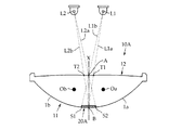
まず、図1を参照して、この第1実施形態に係る分割レンズ10Aは、先の図7で説明したのと同じく、レンズ中心Oa,Obをそれぞれ有する2つの凸レンズ素子1a,1bを成形金型内で例えばアクリル樹脂等にて一体成形してなる2分割レンズであり、素子間の境界面をXとする。なお、別個に形成された2つの凸レンズ素子1a,1bを一体的に接合した2分割レンズであってもよいが、一体成形の2分割レンズにおいて、境界面Xは実際には存在しない仮想の境界面である。
First, referring to FIG. 1, split
また、この第1実施形態においても、図2に示すように、分割レンズ10Aの上方に2つの素子L1,L2が配置され、したがって、レンズ上面が光入射面12で、レンズ下面が光出射面11である。素子L1,L2は、ともに赤外線発光素子である。
Also in the first embodiment, as shown in FIG. 2, the two elements L1 and L2 are arranged above the
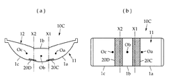
この第1実施形態では、分割レンズ10Aの出射面11側に、迷光を低減(削減)するための遮光性マスク20Aが設けられる。この第1実施形態において、遮光性マスク20Aは、シボ加工によりレンズ表面に形成された梨地からなる(以下に説明する各実施形態も同様)。
In the first embodiment, a light-
好ましい例として、梨地(シボ)の深さ平均値を24〜29μmとすることにより、梨地の有り無しで、迷光部分の反射レベルを比較すると、80%以上の光線を遮ることができる。この意味において、本明細書における「遮光性マスク」なる用語は、光線を100%完全に遮ることを意図するものでなく、好ましくは80%以上の光線を遮るもしくは分散させる手段であることを理解されたい。 As a preferable example, by setting the average depth of the textured surface to 24 to 29 μm, when the reflection level of the stray light portion is compared with or without the textured surface, 80% or more of light rays can be blocked. In this sense, the term “light-shielding mask” in the present specification is not intended to completely block light 100%, but preferably is a means for blocking or dispersing 80% or more of light. I want to be.
なお、上記のような深さ平均値を24〜29μmの梨地を得るにあたっては、成形金型面の抜き勾配を、現在の技術での限界値である3〜4゜とし、また、成形金型面をあらかじめ#320〜#400番手のサンドペーパーで仕上げるとよい。 In order to obtain a satin having an average depth of 24 to 29 μm as described above, the draft of the molding die surface is set to 3 to 4 °, which is the limit value in the current technology, and the molding die The surface may be finished with # 320- # 400 sandpaper in advance.
次に、図2により、分割レンズ10Aの光出射面11側に、遮光性マスク20Aを形成する範囲について説明する。なお、図2の2素子×2分割レンズの組み合わせの場合、4つのスポット光が得られるが、図2にはレンズ中心Oa,Obを通るスポット光線は省略されている。
Next, the range in which the light-
素子L1,L2が凸レンズ素子1a,1bの境界面Xを中心としてほぼ左右対称に配置されており、分割レンズ10Aの光入射面12と境界面Xとの交点をA,光出射面11と境界面Xとの交点をBとする。
Elements L1 and L2 are arranged substantially symmetrically about the boundary surface X of the
素子L1から照射される赤外光のうち境界面Xを横切るのは、素子L1と交点Bとを含む仮想直線L1aと、素子L1と交点Aとを含む仮想直線L1bとの間に存在する光線であるから、素子L1による迷光は、仮想直線L1bと光出射面11との交点S1と、交点Bとの間の範囲内に現れる。
Of the infrared light emitted from the element L1, the ray crossing the boundary plane X is a light ray existing between a virtual straight line L1a including the element L1 and the intersection B and a virtual straight line L1b including the element L1 and the intersection A. Therefore, the stray light from the element L1 appears in the range between the intersection S1 between the virtual straight line L1b and the
同様に、素子L2から照射される赤外光のうち境界面Xを横切るのは、素子L2と交点Bとを含む仮想直線L2bと、素子L2と交点Aとを含む仮想直線L2aとの間に存在する光線であるから、素子L2による迷光は、仮想直線L2aと光出射面11との交点S2と、交点Bとの間の範囲内に現れる。
Similarly, the infrared light irradiated from the element L2 crosses the boundary surface X between the virtual straight line L2b including the element L2 and the intersection B and the virtual straight line L2a including the element L2 and the intersection A. Since it is an existing light beam, the stray light from the element L2 appears in a range between the intersection point S2 between the virtual straight line L2a and the
したがって、この第1実施形態においては、分割レンズ10Aの光出射面11のうちのS1−B−S2の範囲にかけて、梨地からなる遮光性マスク20Aが設けられることになる。
Therefore, in the first embodiment, the light-shielding
なお、境界面Xを横切る光線とは、分割レンズ内で一方の凸レンズ素子から他方の凸レンズ素子に向かう光線であり、境界面Xの真上に配置される素子から迷光は生じない。 The light beam crossing the boundary surface X is a light beam traveling from one convex lens element to the other convex lens element in the split lens, and stray light is not generated from the element arranged directly above the boundary surface X.
第1実施形態の別の態様として、迷光を低減するには、境界面Xを横切る光線を分割レンズの光入射面側で遮ってもよい。図2において、素子L1と交点Bとを含む仮想直線L1aと光入射面12との交点をT1,素子L2と交点Bとを含む仮想直線L2bと光入射面12との交点をT2とすると、素子L1,L2から照射される赤外光のうち、境界面Xに向かうのはT1−A−T2の範囲内の光線である。
As another aspect of the first embodiment, in order to reduce stray light, a light beam crossing the boundary surface X may be blocked on the light incident surface side of the split lens. In FIG. 2, when the intersection of the virtual line L1a including the element L1 and the intersection B and the
このことから、図3に示す第2実施形態に係る分割レンズ(2分割レンズ)10Bにおいては、その光入射面12のうちのT1−A−T2の範囲にかけて、梨地からなる遮光性マスク20Bを備えている。
Therefore, in the split lens (two-split lens) 10B according to the second embodiment shown in FIG. 3, the light-shielding
次に、図4,5を参照して、本発明の第3実施形態に係る分割レンズ10Cについて説明する。
Next, a
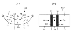
この分割レンズ10Cは、レンズ中心Oa,Ob,Ocをそれぞれ有する3の凸レンズ素子1a,1b,1cを成形金型内で例えばアクリル樹脂等にて一体成形してなる3分割レンズであり、素子1a,1b間の境界面をX1とし、素子1b,1c間の境界面をX2とする。なお、別個に形成された2つの凸レンズ素子1a,1b,1cを一体的に接合した3分割レンズであってもよい。
The
この第3実施形態においては、図5に示すように、分割レンズ10Cの上方に3つの素子L1,L2,L3が配置される。素子L1,L2,L3は、ともに赤外線発光素子であり、3素子×3分割レンズの組み合わせであることから、9個のスポット光が得られるが、図6にはレンズ中心Oa,Ob,Ocを通るスポット光線は省略されている。
In the third embodiment, as shown in FIG. 5, the three elements above the
この第3実施形態では、分割レンズ10Cが3分割レンズで、その内部に2つの境界面X1,X2があることから、光出射面11の2箇所に迷光を低減するための遮光性マスク20C,20Dが設けられる。
In the third embodiment, the dividing
これについて図5により説明するが、まず、光入射面12と第1境界面X1との交点をA1,光入射面12と第2境界面X2との交点をA2,光出射面11と第1境界面X1との交点をB1,光出射面11と第2境界面X2との交点をB2とする。また、素子L2を挟んで素子L1がその右側,素子L3がその左側に配置されているものとする。
This will be described with reference to FIG. 5. First, the intersection of the
素子L1から照射される赤外光のうち第1境界面X1を横切るのは、素子L1と交点B1とを含む仮想直線L1aと、素子L1と交点A1とを含む仮想直線L1bとの間に存在する光線であり、また、第2境界面X2を横切るのは、素子L1と交点B2とを含む仮想直線L1cと、素子L1と交点A2とを含む仮想直線L1dとの間に存在する光線である。 The infrared light irradiated from the element L1 crosses the first boundary surface X1 between a virtual straight line L1a including the element L1 and the intersection B1 and a virtual straight line L1b including the element L1 and the intersection A1. Further, the light ray that crosses the second boundary surface X2 is a light ray that exists between a virtual straight line L1c that includes the element L1 and the intersection B2, and a virtual straight line L1d that includes the element L1 and the intersection A2. .
したがって、光出射面11において、素子L1による迷光は、仮想直線L1bと光出射面11との交点S1と、交点B1との間と、仮想直線L1dと光出射面11との交点S2と、交点B2との間にそれぞれ現れる。
Accordingly, stray light from the element L1 on the
同様に、素子L2から照射される赤外光のうち第1境界面X1を横切るのは、素子L2と交点B1とを含む仮想直線L2bと、素子L2と交点A1とを含む仮想直線L2aとの間に存在する光線であり、また、第2境界面X2を横切るのは、素子L2と交点B2とを含む仮想直線L2cと、素子L2と交点A2とを含む仮想直線L2dとの間に存在する光線である。 Similarly, the infrared light irradiated from the element L2 crosses the first boundary surface X1 between the virtual straight line L2b including the element L2 and the intersection B1, and the virtual straight line L2a including the element L2 and the intersection A1. A light ray that exists between them, and that crosses the second boundary surface X2 exists between a virtual straight line L2c that includes the element L2 and the intersection B2, and a virtual straight line L2d that includes the element L2 and the intersection A2. Light rays.
したがって、光出射面11において、素子L2による迷光は、仮想直線L2aと光出射面11との交点S3と、交点B1との間と、仮想直線L2dと光出射面11との交点S4と、交点B2との間にそれぞれ現れる。
Accordingly, stray light from the element L2 on the
同様に、素子L3から照射される赤外光のうち第1境界面X1を横切るのは、素子L3と交点B1とを含む仮想直線L3bと、素子L3と交点A1とを含む仮想直線L3aとの間に存在する光線であり、また、第2境界面X2を横切るのは、素子L3と交点B2とを含む仮想直線L3dと、素子L3と交点A2とを含む仮想直線L3cとの間に存在する光線である。 Similarly, the infrared light irradiated from the element L3 crosses the first boundary surface X1 between the virtual straight line L3b including the element L3 and the intersection B1, and the virtual straight line L3a including the element L3 and the intersection A1. A light ray that exists between them, and that crosses the second boundary surface X2 exists between a virtual straight line L3d that includes the element L3 and the intersection B2, and a virtual straight line L3c that includes the element L3 and the intersection A2. Light rays.
したがって、光出射面11において、素子L3による迷光は、仮想直線L3aと光出射面11との交点S5と、交点B1との間と、仮想直線L3cと光出射面11との交点S6と、交点B2との間にそれぞれ現れる。
Accordingly, stray light from the element L3 on the
このことから、この第3実施形態においては、図4,図5に示すように、分割レンズ10Cの光出射面11のうちの第1境界面X1側のS1−B1−S3−S5にかけての範囲と、第2境界面X2側のS2−S4−B2−S6にかけての範囲とに、梨地からなる遮光性マスク20C,20Dを備える。
Therefore, in the third embodiment, as shown in FIGS. 4 and 5, the range from S1-B1-S3-S5 on the first boundary surface X1 side of the
第3実施形態の別の態様として、上記第2実施形態と同じく、迷光を低減するには、境界面Xを横切る光線を分割レンズの光入射面側で遮ってもよい。 As another aspect of the third embodiment, similarly to the second embodiment, in order to reduce stray light, a light beam crossing the boundary surface X may be blocked on the light incident surface side of the split lens.
図5において、素子L1と交点B1とを含む仮想直線L1aと光入射面12との交点をT1,素子L1と交点B2とを含む仮想直線L1cと光入射面12との交点をT2,素子L2と交点B1とを含む仮想直線L2bと光入射面12との交点をT3,素子L2と交点B2とを含む仮想直線L2cと光入射面12との交点をT4,素子L3と交点B1とを含む仮想直線L3bと光入射面12との交点をT5,素子L3と交点B2とを含む仮想直線L3dと光入射面12との交点をT6とする。
In FIG. 5, the intersection of the virtual straight line L1a including the element L1 and the intersection B1 and the
この場合、素子L1,L2,L3から照射される赤外光のうち、第1境界面X1に向かうのはT1−A1−T3−T5にかけての範囲内の光線であり、また、第2境界面X2に向かうのはT2−T4−A2−T6にかけての範囲内の光線である。 In this case, out of the infrared light irradiated from the elements L1, L2, and L3, the light traveling toward the first boundary surface X1 is a light beam in the range from T1-A1-T3-T5, and the second boundary surface. It is a ray in the range from T2-T4-A2-T6 that goes to X2.
このことから、図6に示す第4実施形態に係る分割レンズ(3分割レンズ)10Dにおいては、その光入射面12のうちの第1境界面X1側のT1−A1−T3−T5にかけての範囲と、第2境界面X2側のT2−T4−A2−T6にかけての範囲とに、梨地からなる遮光性マスク20E,20Fを備える。
Therefore, in the split lens (three-split lens) 10D according to the fourth embodiment shown in FIG. 6, the range from T1-A1-T3-T5 on the first boundary surface X1 side of the
上記各実施形態において、遮光性マスク20A〜20Fは、分割レンズの光出射面11または光入射面12のいずれか一方に形成するようにしているが、光出射面11と光入射面12の両面に形成してもよい。
In each of the above embodiments, the light-shielding
また、遮光性マスク20A〜20Fをシボ加工による梨地面としているが、これ以外に遮光テープを貼り付けてもよいし、遮光塗料を塗布してもよく、自動ドア用反射式センサについて言えば、迷光による誤検知が生じないように、迷光の遮光率が好ましくは80%以上となるマスク処理であれば、仕様に応じて任意に選択されてよい。
Moreover, although the light-shielding
また、上記各実施形態において、分割レンズは発光素子を有する発光部側用として説明しているが、本発明の分割レンズは受光部側に用いられてもよい。また、本発明は4分割以上の分割レンズにも適用可能である。 Further, in each of the above embodiments, the split lens is described for the light emitting unit side having the light emitting element, but the split lens of the present invention may be used on the light receiving unit side. The present invention can also be applied to a split lens having four or more splits.
10A〜10D 分割レンズ
11 光出射面
12 光入射面
20A〜20F 遮光性マスク
1a〜1c 凸レンズ素子
Oa〜Oc レンズ中心
L1〜L3 発光素子
X1,X2 境界面
10A to
Claims (5)
上記分割レンズの光入射面および/または光出射面自体に、上記発光素子から照射される光のうち隣接する上記凸レンズ素子間の境界面を横切る光による迷光を低減させる遮光性マスクを備えており、
上記光入射面と上記境界面との交点をA,上記光出射面と上記境界面との交点をB,上記発光素子と上記交点Aとを含む第1仮想直線と上記光出射面との交点をS,上記発光素子と上記交点Bとを含む第2仮想直線と上記光入射面との交点をTとして、
上記遮光性マスクは、上記光出射面側の上記交点Sと交点Bとの間および/または上記光入射面側の上記交点Tと交点Aとの間に設けられることを特徴とする自動ドア用反射式センサ。 A split lens in which a plurality of convex lens elements are integrally joined; and a plurality of light emitting elements, wherein the adjacent light emitting elements are centered on a surface including a boundary surface between the convex lens elements on the light incident surface side of the split lenses. substantially are arranged symmetrically, in the reflection-type sensor for an automatic door that will be divided into a plurality of light beams passing through the center for each light above the convex lenses elements emitted from the respective light emitting elements as,
The light entrance surface and / or the light exit surface of the split lens is provided with a light-shielding mask that reduces stray light caused by light crossing the boundary surface between the adjacent convex lens elements among the light emitted from the light emitting elements. ,
The intersection of the light incident surface and the boundary surface is A, the intersection of the light emission surface and the boundary surface is B, and the intersection of the first virtual straight line including the light emitting element and the intersection A and the light emission surface S, and the intersection of the second imaginary straight line including the light emitting element and the intersection B and the light incident surface is T,
The light-shielding mask is provided between the intersection S and the intersection B on the light emitting surface side and / or between the intersection T and the intersection A on the light incident surface side . Reflective sensor .
Priority Applications (1)
| Application Number | Priority Date | Filing Date | Title |
|---|---|---|---|
| JP2013012968A JP6317543B2 (en) | 2013-01-28 | 2013-01-28 | Reflective sensor for automatic door |
Applications Claiming Priority (1)
| Application Number | Priority Date | Filing Date | Title |
|---|---|---|---|
| JP2013012968A JP6317543B2 (en) | 2013-01-28 | 2013-01-28 | Reflective sensor for automatic door |
Publications (2)
| Publication Number | Publication Date |
|---|---|
| JP2014145816A JP2014145816A (en) | 2014-08-14 |
| JP6317543B2 true JP6317543B2 (en) | 2018-04-25 |
Family
ID=51426141
Family Applications (1)
| Application Number | Title | Priority Date | Filing Date |
|---|---|---|---|
| JP2013012968A Active JP6317543B2 (en) | 2013-01-28 | 2013-01-28 | Reflective sensor for automatic door |
Country Status (1)
| Country | Link |
|---|---|
| JP (1) | JP6317543B2 (en) |
Families Citing this family (1)
| Publication number | Priority date | Publication date | Assignee | Title |
|---|---|---|---|---|
| JP6638383B2 (en) * | 2015-12-24 | 2020-01-29 | セイコーエプソン株式会社 | Virtual image display |
Family Cites Families (4)
| Publication number | Priority date | Publication date | Assignee | Title |
|---|---|---|---|---|
| JPS63153501A (en) * | 1986-12-17 | 1988-06-25 | Nippon Sheet Glass Co Ltd | Lens array plate and its production |
| KR970010008B1 (en) * | 1995-04-13 | 1997-06-20 | 삼성전자 주식회사 | Infrared Object Detection Device |
| FI20095065A0 (en) * | 2009-01-26 | 2009-01-26 | Wallac Oy | Combination of lens and reflector and optical device using the same |
| US9347644B2 (en) * | 2011-04-22 | 2016-05-24 | Sharp Kabushiki Kaisha | Lens and light source unit |
-
2013
- 2013-01-28 JP JP2013012968A patent/JP6317543B2/en active Active
Also Published As
| Publication number | Publication date |
|---|---|
| JP2014145816A (en) | 2014-08-14 |
Similar Documents
| Publication | Publication Date | Title |
|---|---|---|
| JP6558166B2 (en) | Optical device and operation input device | |
| JP5085631B2 (en) | Optical imaging apparatus and optical imaging method using the same | |
| JP6372305B2 (en) | Blind spot assist device | |
| US9851478B2 (en) | Optical cross talk mitigation for optical device having disrupting features formed on a shield | |
| CN112540495A (en) | Polarized lens and light supplementing method of monitoring assembly | |
| TWI737720B (en) | Lens | |
| JP2000235000A (en) | Light-scattering-type particle detection sensor | |
| RU2763122C1 (en) | Augmented and combined reality screen | |
| CN203870371U (en) | Optical filter that inhibits partial overexposure and monitoring camera internally equipped with optical filter | |
| US20230074490A1 (en) | Reflective structure, reflective structure array comprising same, and floating image display device | |
| JP6317543B2 (en) | Reflective sensor for automatic door | |
| KR20220004709A (en) | Screen fingerprint recognition assembly and terminal equipment | |
| CN105050880B (en) | Optical Signal | |
| JP4790874B2 (en) | Imaging device | |
| WO2015151388A1 (en) | Infrared sensor | |
| TW201721276A (en) | Light source module | |
| JP6531583B2 (en) | Optical device, optical system and ticket gate | |
| CN215006043U (en) | Optical system, optical lens and TOF camera module | |
| JP6464733B2 (en) | Blind spot assist device | |
| US20190064354A1 (en) | Optical sensor arrangement | |
| US12216378B2 (en) | Projection device and projection method | |
| US20240168363A1 (en) | Projection device and projection method | |
| US11268833B2 (en) | Reflection type sensor and optical encoder having the same | |
| CN212341496U (en) | An optical waveguide lens | |
| JP2014132327A (en) | Projection display device housing and projection display device housing with projection display device housing |
Legal Events
| Date | Code | Title | Description |
|---|---|---|---|
| A621 | Written request for application examination |
Free format text: JAPANESE INTERMEDIATE CODE: A621 Effective date: 20160127 |
|
| A977 | Report on retrieval |
Free format text: JAPANESE INTERMEDIATE CODE: A971007 Effective date: 20161130 |
|
| A131 | Notification of reasons for refusal |
Free format text: JAPANESE INTERMEDIATE CODE: A131 Effective date: 20161207 |
|
| A521 | Request for written amendment filed |
Free format text: JAPANESE INTERMEDIATE CODE: A523 Effective date: 20170206 |
|
| A131 | Notification of reasons for refusal |
Free format text: JAPANESE INTERMEDIATE CODE: A131 Effective date: 20170726 |
|
| A521 | Request for written amendment filed |
Free format text: JAPANESE INTERMEDIATE CODE: A523 Effective date: 20170925 |
|
| TRDD | Decision of grant or rejection written | ||
| A01 | Written decision to grant a patent or to grant a registration (utility model) |
Free format text: JAPANESE INTERMEDIATE CODE: A01 Effective date: 20180228 |
|
| A61 | First payment of annual fees (during grant procedure) |
Free format text: JAPANESE INTERMEDIATE CODE: A61 Effective date: 20180330 |
|
| R150 | Certificate of patent or registration of utility model |
Ref document number: 6317543 Country of ref document: JP Free format text: JAPANESE INTERMEDIATE CODE: R150 |
|
| R250 | Receipt of annual fees |
Free format text: JAPANESE INTERMEDIATE CODE: R250 |
|
| R250 | Receipt of annual fees |
Free format text: JAPANESE INTERMEDIATE CODE: R250 |