JP6317448B2 - ソレノイド駆動式ゲートバルブ - Google Patents
ソレノイド駆動式ゲートバルブ Download PDFInfo
- Publication number
- JP6317448B2 JP6317448B2 JP2016538555A JP2016538555A JP6317448B2 JP 6317448 B2 JP6317448 B2 JP 6317448B2 JP 2016538555 A JP2016538555 A JP 2016538555A JP 2016538555 A JP2016538555 A JP 2016538555A JP 6317448 B2 JP6317448 B2 JP 6317448B2
- Authority
- JP
- Japan
- Prior art keywords
- gate
- opening
- check valve
- valve
- elastic band
- Prior art date
- Legal status (The legal status is an assumption and is not a legal conclusion. Google has not performed a legal analysis and makes no representation as to the accuracy of the status listed.)
- Active
Links
- 239000012530 fluid Substances 0.000 claims description 45
- 230000007246 mechanism Effects 0.000 claims description 24
- 230000002093 peripheral effect Effects 0.000 claims description 22
- 230000008878 coupling Effects 0.000 claims description 12
- 238000010168 coupling process Methods 0.000 claims description 12
- 238000005859 coupling reaction Methods 0.000 claims description 12
- 238000007789 sealing Methods 0.000 claims description 10
- 238000004891 communication Methods 0.000 claims description 8
- 230000000712 assembly Effects 0.000 claims description 2
- 238000000429 assembly Methods 0.000 claims description 2
- 238000002955 isolation Methods 0.000 claims 1
- 230000000717 retained effect Effects 0.000 claims 1
- 238000003780 insertion Methods 0.000 description 13
- 230000037431 insertion Effects 0.000 description 12
- 239000013013 elastic material Substances 0.000 description 5
- 230000006870 function Effects 0.000 description 5
- 230000004044 response Effects 0.000 description 4
- 230000008901 benefit Effects 0.000 description 3
- 238000007906 compression Methods 0.000 description 3
- 238000013461 design Methods 0.000 description 3
- 239000000463 material Substances 0.000 description 3
- XEEYBQQBJWHFJM-UHFFFAOYSA-N Iron Chemical compound [Fe] XEEYBQQBJWHFJM-UHFFFAOYSA-N 0.000 description 2
- 230000009471 action Effects 0.000 description 2
- 230000009286 beneficial effect Effects 0.000 description 2
- 230000008859 change Effects 0.000 description 2
- 239000000696 magnetic material Substances 0.000 description 2
- 230000001052 transient effect Effects 0.000 description 2
- 238000004026 adhesive bonding Methods 0.000 description 1
- 239000000956 alloy Substances 0.000 description 1
- 229910045601 alloy Inorganic materials 0.000 description 1
- 239000011324 bead Substances 0.000 description 1
- 239000000084 colloidal system Substances 0.000 description 1
- 239000002131 composite material Substances 0.000 description 1
- 230000006835 compression Effects 0.000 description 1
- 238000010276 construction Methods 0.000 description 1
- 238000010586 diagram Methods 0.000 description 1
- 238000007599 discharging Methods 0.000 description 1
- 238000006073 displacement reaction Methods 0.000 description 1
- 239000013536 elastomeric material Substances 0.000 description 1
- 239000007789 gas Substances 0.000 description 1
- 230000014509 gene expression Effects 0.000 description 1
- 230000017525 heat dissipation Effects 0.000 description 1
- 229910052742 iron Inorganic materials 0.000 description 1
- 239000007788 liquid Substances 0.000 description 1
- 230000005291 magnetic effect Effects 0.000 description 1
- 238000004519 manufacturing process Methods 0.000 description 1
- 238000000034 method Methods 0.000 description 1
- 238000012986 modification Methods 0.000 description 1
- 230000004048 modification Effects 0.000 description 1
- 229920003052 natural elastomer Polymers 0.000 description 1
- 229920001194 natural rubber Polymers 0.000 description 1
- 239000002907 paramagnetic material Substances 0.000 description 1
- 238000003825 pressing Methods 0.000 description 1
- 230000009467 reduction Effects 0.000 description 1
- 230000008771 sex reversal Effects 0.000 description 1
- 239000000725 suspension Substances 0.000 description 1
- 229920003051 synthetic elastomer Polymers 0.000 description 1
- 239000005061 synthetic rubber Substances 0.000 description 1
- 230000009466 transformation Effects 0.000 description 1
- 238000009423 ventilation Methods 0.000 description 1
- 238000013022 venting Methods 0.000 description 1
- 229910000859 α-Fe Inorganic materials 0.000 description 1
Images


Classifications
-
- F—MECHANICAL ENGINEERING; LIGHTING; HEATING; WEAPONS; BLASTING
- F16—ENGINEERING ELEMENTS AND UNITS; GENERAL MEASURES FOR PRODUCING AND MAINTAINING EFFECTIVE FUNCTIONING OF MACHINES OR INSTALLATIONS; THERMAL INSULATION IN GENERAL
- F16K—VALVES; TAPS; COCKS; ACTUATING-FLOATS; DEVICES FOR VENTING OR AERATING
- F16K3/00—Gate valves or sliding valves, i.e. cut-off apparatus with closing members having a sliding movement along the seat for opening and closing
- F16K3/02—Gate valves or sliding valves, i.e. cut-off apparatus with closing members having a sliding movement along the seat for opening and closing with flat sealing faces; Packings therefor
- F16K3/0254—Gate valves or sliding valves, i.e. cut-off apparatus with closing members having a sliding movement along the seat for opening and closing with flat sealing faces; Packings therefor being operated by particular means
-
- F—MECHANICAL ENGINEERING; LIGHTING; HEATING; WEAPONS; BLASTING
- F02—COMBUSTION ENGINES; HOT-GAS OR COMBUSTION-PRODUCT ENGINE PLANTS
- F02M—SUPPLYING COMBUSTION ENGINES IN GENERAL WITH COMBUSTIBLE MIXTURES OR CONSTITUENTS THEREOF
- F02M35/00—Combustion-air cleaners, air intakes, intake silencers, or induction systems specially adapted for, or arranged on, internal-combustion engines
- F02M35/10—Air intakes; Induction systems
- F02M35/10209—Fluid connections to the air intake system; their arrangement of pipes, valves or the like
- F02M35/10229—Fluid connections to the air intake system; their arrangement of pipes, valves or the like the intake system acting as a vacuum or overpressure source for auxiliary devices, e.g. brake systems; Vacuum chambers
-
- F—MECHANICAL ENGINEERING; LIGHTING; HEATING; WEAPONS; BLASTING
- F02—COMBUSTION ENGINES; HOT-GAS OR COMBUSTION-PRODUCT ENGINE PLANTS
- F02M—SUPPLYING COMBUSTION ENGINES IN GENERAL WITH COMBUSTIBLE MIXTURES OR CONSTITUENTS THEREOF
- F02M35/00—Combustion-air cleaners, air intakes, intake silencers, or induction systems specially adapted for, or arranged on, internal-combustion engines
- F02M35/10—Air intakes; Induction systems
- F02M35/10242—Devices or means connected to or integrated into air intakes; Air intakes combined with other engine or vehicle parts
- F02M35/10255—Arrangements of valves; Multi-way valves
-
- F—MECHANICAL ENGINEERING; LIGHTING; HEATING; WEAPONS; BLASTING
- F16—ENGINEERING ELEMENTS AND UNITS; GENERAL MEASURES FOR PRODUCING AND MAINTAINING EFFECTIVE FUNCTIONING OF MACHINES OR INSTALLATIONS; THERMAL INSULATION IN GENERAL
- F16K—VALVES; TAPS; COCKS; ACTUATING-FLOATS; DEVICES FOR VENTING OR AERATING
- F16K3/00—Gate valves or sliding valves, i.e. cut-off apparatus with closing members having a sliding movement along the seat for opening and closing
- F16K3/02—Gate valves or sliding valves, i.e. cut-off apparatus with closing members having a sliding movement along the seat for opening and closing with flat sealing faces; Packings therefor
- F16K3/16—Gate valves or sliding valves, i.e. cut-off apparatus with closing members having a sliding movement along the seat for opening and closing with flat sealing faces; Packings therefor with special arrangements for separating the sealing faces or for pressing them together
- F16K3/18—Gate valves or sliding valves, i.e. cut-off apparatus with closing members having a sliding movement along the seat for opening and closing with flat sealing faces; Packings therefor with special arrangements for separating the sealing faces or for pressing them together by movement of the closure members
-
- F—MECHANICAL ENGINEERING; LIGHTING; HEATING; WEAPONS; BLASTING
- F16—ENGINEERING ELEMENTS AND UNITS; GENERAL MEASURES FOR PRODUCING AND MAINTAINING EFFECTIVE FUNCTIONING OF MACHINES OR INSTALLATIONS; THERMAL INSULATION IN GENERAL
- F16K—VALVES; TAPS; COCKS; ACTUATING-FLOATS; DEVICES FOR VENTING OR AERATING
- F16K3/00—Gate valves or sliding valves, i.e. cut-off apparatus with closing members having a sliding movement along the seat for opening and closing
- F16K3/30—Details
- F16K3/314—Forms or constructions of slides; Attachment of the slide to the spindle
-
- F—MECHANICAL ENGINEERING; LIGHTING; HEATING; WEAPONS; BLASTING
- F16—ENGINEERING ELEMENTS AND UNITS; GENERAL MEASURES FOR PRODUCING AND MAINTAINING EFFECTIVE FUNCTIONING OF MACHINES OR INSTALLATIONS; THERMAL INSULATION IN GENERAL
- F16K—VALVES; TAPS; COCKS; ACTUATING-FLOATS; DEVICES FOR VENTING OR AERATING
- F16K31/00—Actuating devices; Operating means; Releasing devices
- F16K31/02—Actuating devices; Operating means; Releasing devices electric; magnetic
- F16K31/06—Actuating devices; Operating means; Releasing devices electric; magnetic using a magnet, e.g. diaphragm valves, cutting off by means of a liquid
- F16K31/0644—One-way valve
- F16K31/0668—Sliding valves
Description
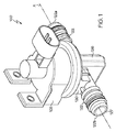
102 ハウジング
104 ソレノイドコイル
106 アーマチャー
106a 挿入端部
106b 非挿入端部
107 隣接ボディ部分
108 内部リセス
110 付勢要素
112 コイルスプリング
114 アーマチャーステム
114a 接続開口端部
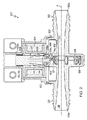
120 バルブ機構
122 導管
122a 入口端部
122b 出口端部
124 接続開口(コネクター開口)
125 断面
126 ポケット
127 断面
128 スプラングゲートアセンブリ(スライドゲートアセンブリ)
128a 接続開口端部
160 レールシステム
162 ガイドレール
164 レースウェイ溝(レーストラック溝)
166 スライダー
167 ヘッド
168 マルチパートソケット
170 ベントポート
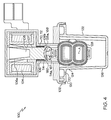
180 エアインテーク
182 エアインタークーラー
184 インテークマニホールド
190 アスピレーター
192 チェックバルブ
194 パワーブレーキブースター
228,228’ スプラングゲートアセンブリ
228a 接続開口端部
229,229’ 通路
230 第1のゲート部材(硬質ゲート部材)
230’ 第1のゲート部材
232 第2のゲート部材(硬質ゲート部材)
232’ 第2のゲート部材
233,233’ 開口
234 エンドレス弾性帯
235 8の字形状帯
235’ エンドレス弾性帯
236,237,237’ トラック
240,240’ 開ポジション部分
242,242’ 閉ポジション部分
244’ 開口
250 外面
252,252’ 内面
253’ プラグ
254 チャネル
266,266’ スライダー
268 マルチパートソケット
272 第1の内周面
273 第2の内周面
274 外周面
276 第1の側面
278 第2の側面
281 ラッチ
282 内周面
283 デテント
284 外周面
286 第1の側面
288 第2の側面
328 ユニバーサルスプラングゲート
332 第2のゲート部材
333 第1の開口
334 インナーゲート部材
336 開口
344 第2の開口
346 第1のエンドレス弾性帯(8の字形状エンドレス弾性帯)
348 第2のエンドレス弾性帯
352 第1のトラック
354 第2のトラック
366 スライダー
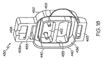
428 スプラングゲートアセンブリ(スライドゲートアセンブリ)
428a 接続開口端部
429 通路
430 第1のゲート部材
432 第2のゲート部材
433 開口
434 エンドレス弾性帯
436 トラック
438 チャンバー
440 開ポジション部分
442 閉ポジション部分
450 連続的外面
451 リセス
452 内面
454 チャネル
456 チェックバルブ開口
458 チェックバルブリテーナー開口
459 停止ポスト
468 マルチパートソケット
481 ラッチ
482 内周面
483 デテント
484 外周面
486 第1の側面
488 第2の側面
490 チェックバルブ部材
492 シール面
494 チェックバルブリテーナー
495 ネック部分
496 ヘッド部分
497 犠牲タブ延長部
498 リテーナーストッパー
Claims (21)
- 動力式ゲートバルブであって、
ソレノイドコイルと、バルブ機構に接続されたアーマチャーと、を備え、
前記バルブ機構は、
接続開口と、対向配置されたポケットと、を有する導管と、
前記接続開口と前記ポケットとの間で直線的に移動可能なスプラングゲートアセンブリと、を含み、
前記スプラングゲートアセンブリは、開口を有する第1のゲート部材と、開口を有すると共に前記第1のゲート部材と対向する第2のゲート部材と、前記第1および第2のゲート部材間に保持されたエンドレス弾性帯と、を含み、前記開口およびエンドレス弾性帯は、前記スプラングゲートアセンブリを通過する通路を協働で画定し、かつ、
前記第1および第2のゲート部材は、前記接続開口と前記ポケットとの間での往復直線運動のために、前記アーマチャーに対して機械的に結合されており、
前記第2のゲート部材は、外側向きリセスと、前記外側向きリセス内に配置されたチェックバルブ開口と、前記第1および第2のゲート部材および前記エンドレス弾性帯によって形成されたチャンバーからの流れに対して前記チェックバルブ開口を選択的に密封するように前記チェックバルブ開口に隣接して配置されたチェックバルブと、を有する、動力式ゲートバルブ。 - 機械的結合部は、前記アーマチャーから突出するステムを備え、かつ、前記ステムの接続開口端部は前記スプラングゲートアセンブリに固定されている、請求項1に記載の動力式ゲートバルブ。
- 機械的結合部は、前記アーマチャーから突出するステムと、前記導管の長手方向縦軸と平行な方向の前記ステムと前記スプラングゲートアセンブリとの間の相対的スライド移動を許容するように前記ステムの接続開口端部と前記スプラングゲートアセンブリの接続開口端部とを相互接続するレールシステムと、を備える、請求項1に記載の動力式ゲートバルブ。
- 前記ステムの前記接続開口端部および前記スプリングゲートアセンブリの前記接続開口端部の一方はガイドレールを含み、かつ、前記ステムの前記接続開口端部および前記スプリングゲートアセンブリの前記接続開口端部の他方は、前記ガイドレールの周囲を取り囲むように構成されたスライダーを含む、請求項3に記載の動力式ゲートバルブ。
- 機械的結合部は前記アーマチャーから突出するステムを備え、前記ステムの前記接続開口端部は拡大されたプレート状ヘッドを含み、かつ、少なくとも前記第1および第2のゲート部材の接続開口端部は、協働で、前記プレート状ヘッドを取り囲むソケットを形成する、請求項1に記載の動力式ゲートバルブ。
- 前記第1および第2のゲート部材はそれぞれ、前記エンドレス弾性帯の一部を受け容れるためのトラックを含み、前記トラックおよびエンドレス弾性帯は、前記エンドレス帯が前記トラック内に着座させられたとき前記第1および第2のゲート部材が非ゼロ距離だけ互いに離間させられるように構成され、前記トラックは、前記第1および第2のゲート部材間に配置された前記エンドレス弾性帯の外面の周りにチャネルを形成するように、前記第1および第2のゲート部材の外周から、ある距離だけ前記エンドレス弾性帯を奥まった所に置くように配置される、請求項1に記載の動力式ゲートバルブ。
- 前記接続開口、前記ポケットおよび前記チャネルと流体連通するベントポートをさらに備える、請求項6に記載の動力式ゲートバルブ。
- 前記ポケットは、このポケット内への前記スプラングゲートアセンブリの挿入時に、前記スプラングゲートアセンブリと前記ポケットとの間に締まり嵌めが生じるように、前記スプラングゲートアセンブリが前記ポケットに挿入されていない状態での前記スプラングゲートアセンブリの幅よりも小さな、前記導管の長手方向軸線に対して平行な方向における幅を有する、請求項1に記載の動力式ゲートバルブ。
- 前記第1および第2のゲート部材は閉ポジション部分を含み、前記第1のゲート部材は第2の開口を有し、前記第2のゲート部材は前記第2の開口と対向する実質的に連続した滑らかな外面を有し、前記エンドレス弾性帯は、8の字形状であって、前記8の字形状の対向ループ内で前記通路および前記第2の開口を分離する8の字形状を有する、請求項1に記載の動力式ゲートバルブ。
- 前記第2のゲート部材は前記第2の開口と対向する内面から突出するプラグを有し、前記プラグは、前記8の字形状の隣接ループ内に嵌合するよう構成され、かつ、少なくとも前記第2の開口のサイズとなるような寸法とされている、請求項9に記載の動力式ゲートバルブ。
- 前記第1および第2のゲート部材の一方がラッチを含み、かつ、前記第1および第2のゲート部材の他方が対応するように配置されたデテントを含み、前記ラッチは、組み立て状態において、前記スプラングゲートアセンブリを保持するために前記デテントと係合する、請求項1に記載の動力式ゲートバルブ。
- 前記エンドレス弾性帯は蛇腹壁状の長手方向断面を有する、請求項1に記載の動力式ゲートバルブ。
- 前記外側向きリセスは前記チェックバルブ開口を支える複数のチェックバルブリテーナー開口を含み、かつ、前記チェックバルブは、前記チェックバルブリテーナー開口によって収容されかつ保持される複数のチェックバルブリテーナーを含む、請求項1に記載の動力式ゲートバルブ。
- 前記第1のゲート部材は前記複数のチェックバルブリテーナー開口と対向する内面を有し、かつ、前記内面は、チェックバルブリテーナー開口と整列させられると共に前記チェックバルブと係合する複数の内側に突出する停止ポストを含む、請求項13に記載の動力式ゲートバルブ。
- 前記チェックバルブは略平坦なシール面を含み、かつ、前記チェックバルブリテーナーは、前記チェックバルブリテーナー開口を貫通して延在すると共にそれを塞ぐよう構成された突出ネック部分と、前記チェックバルブリテーナー開口の壁によって干渉的に保持されるよう構成されたヘッド部分と、を備える、請求項13または請求項14に記載の動力式ゲートバルブ。
- 前記チェックバルブは複数のリテーナーストッパーを含み、前記複数のリテーナーストッパーは、前記複数のチェックバルブリテーナーと整列させられ、かつ、前記略平坦なシール面から前記複数のチェックバルブリテーナーと反対の側に突出する、請求項15に記載の動力式ゲートバルブ。
- 前記チェックバルブは、前記チェックバルブ開口を、前記チャンバーと、第1のゲート部材開口と、第2のゲート部材開口と、そして前記外側向きリセスにおける圧力が前記チャンバー内の圧力よりも高い場合には通路と、流体的に相互接続するために選択的に開く、請求項1に記載の動力式ゲートバルブ。
- 前記チェックバルブは、前記チェックバルブ開口を、前記チャンバーから、第1のゲート部材開口から、第2のゲート部材開口から、そして前記外側向きリセスにおける圧力が前記チャンバー内の圧力よりも低い場合には通路から、流体的に切り離すために選択的に閉じる、請求項17に記載の動力式ゲートバルブ。
- スプラングゲートアセンブリであって、
第1のゲート部材および第2のゲート部材であって、それぞれがその開ポジション部分においてそれを貫通する開口を画定し、前記第2のゲート部材は、その閉ポジション部分にチェックバルブ開口を備え、かつ、前記チェックバルブ開口を選択的に密封するチェックバルブ部材を有する、第1のゲート部材および第2のゲート部材と、
エンドレス弾性帯であって、少なくとも第1の開放スペースを画定する内周面を有し、前記スプラングゲートを通過する通路を形成するよう整列させられた前記第1および第2のゲート部材の両方における前記開口との整列のために、その前記第1の開放スペースが配向された状態で、前記第1および第2のゲート部間に圧縮状態で挟み込まれた、エンドレス弾性帯と、を具備し、
前記エンドレス弾性帯は、前記第1および第2のゲート部材に対して、それらを互いに離間させる付勢力を加え、かつ、前記第1のエンドレス弾性帯と、前記第1のゲート部材と、前記第2のゲート部材とは、開ポジションと閉ポジションとの間で、集合的に一緒に移動する、スプラングゲートアセンブリ。 - 前記第1のゲート部材は、前記チェックバルブ部材に向かって、閉ポジション部分の内面から突出する複数の停止ポストを有する、請求項19に記載のスプラングゲートアセンブリ。
- 前記チェックバルブは、略平坦なシール面と、それぞれが前記第2のゲート部材の保持開口を通って延在する突出ネック部分と、前記保持開口を通過した後、前記第2のゲート部材によって干渉的に保持される各突出ネック部分上のヘッド部分と、を含む、請求項19に記載のスプラングゲートアセンブリ。
Applications Claiming Priority (3)
| Application Number | Priority Date | Filing Date | Title |
|---|---|---|---|
| US201361914866P | 2013-12-11 | 2013-12-11 | |
| US61/914,866 | 2013-12-11 | ||
| PCT/US2014/069796 WO2015089305A1 (en) | 2013-12-11 | 2014-12-11 | Solenoid-powered gate valve |
Publications (3)
| Publication Number | Publication Date |
|---|---|
| JP2016540173A JP2016540173A (ja) | 2016-12-22 |
| JP2016540173A5 JP2016540173A5 (ja) | 2017-12-21 |
| JP6317448B2 true JP6317448B2 (ja) | 2018-04-25 |
Family
ID=53371838
Family Applications (1)
| Application Number | Title | Priority Date | Filing Date |
|---|---|---|---|
| JP2016538555A Active JP6317448B2 (ja) | 2013-12-11 | 2014-12-11 | ソレノイド駆動式ゲートバルブ |
Country Status (6)
| Country | Link |
|---|---|
| EP (1) | EP3094897B1 (ja) |
| JP (1) | JP6317448B2 (ja) |
| KR (1) | KR102173206B1 (ja) |
| CN (1) | CN105209806B (ja) |
| BR (1) | BR112016013351B1 (ja) |
| WO (1) | WO2015089305A1 (ja) |
Families Citing this family (5)
| Publication number | Priority date | Publication date | Assignee | Title |
|---|---|---|---|---|
| EP3791094A4 (en) * | 2018-05-07 | 2021-12-08 | Dayco IP Holdings, LLC | TWO-POSITION SLIDER AND SPRING SLIDER WITH A FULLY FLOW OPENING AND A PARTIAL FLOW OPENING POSITION |
| JP7017498B2 (ja) * | 2018-10-19 | 2022-02-08 | 株式会社鷺宮製作所 | 電磁弁 |
| CN109838594B (zh) * | 2019-03-01 | 2020-10-20 | 马鞍山领瞻机械科技有限公司 | 一种防泄漏密封阀 |
| CN111550594B (zh) * | 2020-04-30 | 2022-07-15 | 东莞市安海思精密电子有限公司 | 电磁阀、电磁阀泵阀模组及一体式两联串联式电磁阀 |
| CN115899320B (zh) * | 2023-01-04 | 2023-05-16 | 河北同力自控阀门制造有限公司 | 一种具有泄压结构的可调式单向阀 |
Family Cites Families (18)
| Publication number | Priority date | Publication date | Assignee | Title |
|---|---|---|---|---|
| US2740962A (en) * | 1950-01-05 | 1956-04-03 | Sperry Rand Corp | Three axis tracking system |
| US2816730A (en) * | 1951-04-20 | 1957-12-17 | Rabas Eduard | Shut-off valve |
| US2750962A (en) * | 1955-06-28 | 1956-06-19 | Morton A Kreitchman | Solenoid operated valve structure |
| US3113757A (en) * | 1961-01-18 | 1963-12-10 | Nixon Phillip | Solenoid-operated gate valve |
| US3768774A (en) * | 1971-06-16 | 1973-10-30 | Vetco Offshore Ind Inc | Gate valve with pressure actuated plug seat |
| US4010928A (en) * | 1974-12-27 | 1977-03-08 | Xomox Corporation | Piston-operated parallel-slide gate valve |
| US4056255A (en) * | 1975-05-08 | 1977-11-01 | Lace Donald A | Valve actuator |
| US5000215A (en) * | 1988-04-27 | 1991-03-19 | Phillips Edwin D | Bellows seal for valves and the like |
| US5195722A (en) * | 1990-06-14 | 1993-03-23 | Bedner Michael P | Fool proof slide gate valve |
| US5627504A (en) * | 1992-04-07 | 1997-05-06 | Avl Medical Instruments Ag | Electromagnetic actuating device, in particular for a valve |
| US5377955A (en) * | 1994-02-15 | 1995-01-03 | Baker; Dwight | Gate valve |
| US6158718A (en) * | 1999-09-17 | 2000-12-12 | Erc Industries, Inc. | Gate valve |
| JP3425937B2 (ja) * | 2000-12-04 | 2003-07-14 | 入江工研株式会社 | ゲート弁 |
| CN2480633Y (zh) * | 2001-06-01 | 2002-03-06 | 彭国军 | 楔式双闸板闸阀 |
| US7017886B1 (en) * | 2004-03-17 | 2006-03-28 | Romanus Aniekezie Ngene-Igwe | Sliding gate valve |
| US7523916B2 (en) * | 2006-10-05 | 2009-04-28 | Vetco Gray Inc. | Fail-safe gate valve |
| SG185830A1 (en) * | 2011-05-09 | 2012-12-28 | Cameron Int Corp | Split gate valve with biasing mechanism |
| US8777184B2 (en) * | 2011-06-13 | 2014-07-15 | Tom J. Brock | Gate valve |
-
2014
- 2014-12-11 KR KR1020167016317A patent/KR102173206B1/ko active IP Right Grant
- 2014-12-11 JP JP2016538555A patent/JP6317448B2/ja active Active
- 2014-12-11 EP EP14869954.9A patent/EP3094897B1/en active Active
- 2014-12-11 WO PCT/US2014/069796 patent/WO2015089305A1/en active Application Filing
- 2014-12-11 CN CN201480002180.5A patent/CN105209806B/zh active Active
- 2014-12-11 BR BR112016013351-0A patent/BR112016013351B1/pt active IP Right Grant
Also Published As
| Publication number | Publication date |
|---|---|
| EP3094897B1 (en) | 2018-10-24 |
| WO2015089305A1 (en) | 2015-06-18 |
| JP2016540173A (ja) | 2016-12-22 |
| KR102173206B1 (ko) | 2020-11-03 |
| EP3094897A1 (en) | 2016-11-23 |
| BR112016013351B1 (pt) | 2022-04-19 |
| BR112016013351A2 (ja) | 2017-08-08 |
| KR20160094989A (ko) | 2016-08-10 |
| BR112016013351A8 (pt) | 2020-05-19 |
| CN105209806B (zh) | 2017-04-26 |
| EP3094897A4 (en) | 2017-09-27 |
| CN105209806A (zh) | 2015-12-30 |
Similar Documents
| Publication | Publication Date | Title |
|---|---|---|
| US9574677B2 (en) | Solenoid-powered gate valve | |
| EP3039319B1 (en) | Sprung gate valves movable by a solenoid actuator | |
| JP6317448B2 (ja) | ソレノイド駆動式ゲートバルブ | |
| JP6683828B2 (ja) | スプリング式ゲートバルブ | |
| JP6466418B2 (ja) | アクチュエータによって動作可能なバネ装填式ゲートバルブ | |
| JP6623154B2 (ja) | ソレノイド駆動式ゲートバルブを備えたディーゼルエンジン流体クーラントシステム | |
| JP7160944B2 (ja) | 全流開位置および制限流開位置を有する二位置ゲートおよびばね付勢されたゲートバルブ |
Legal Events
| Date | Code | Title | Description |
|---|---|---|---|
| A521 | Request for written amendment filed |
Free format text: JAPANESE INTERMEDIATE CODE: A523 Effective date: 20171113 |
|
| A621 | Written request for application examination |
Free format text: JAPANESE INTERMEDIATE CODE: A621 Effective date: 20171113 |
|
| A871 | Explanation of circumstances concerning accelerated examination |
Free format text: JAPANESE INTERMEDIATE CODE: A871 Effective date: 20171113 |
|
| A975 | Report on accelerated examination |
Free format text: JAPANESE INTERMEDIATE CODE: A971005 Effective date: 20171211 |
|
| A131 | Notification of reasons for refusal |
Free format text: JAPANESE INTERMEDIATE CODE: A131 Effective date: 20171218 |
|
| A521 | Request for written amendment filed |
Free format text: JAPANESE INTERMEDIATE CODE: A523 Effective date: 20180215 |
|
| TRDD | Decision of grant or rejection written | ||
| A01 | Written decision to grant a patent or to grant a registration (utility model) |
Free format text: JAPANESE INTERMEDIATE CODE: A01 Effective date: 20180305 |
|
| A61 | First payment of annual fees (during grant procedure) |
Free format text: JAPANESE INTERMEDIATE CODE: A61 Effective date: 20180329 |
|
| R150 | Certificate of patent or registration of utility model |
Ref document number: 6317448 Country of ref document: JP Free format text: JAPANESE INTERMEDIATE CODE: R150 |
|
| R250 | Receipt of annual fees |
Free format text: JAPANESE INTERMEDIATE CODE: R250 |
|
| R250 | Receipt of annual fees |
Free format text: JAPANESE INTERMEDIATE CODE: R250 |
|
| R250 | Receipt of annual fees |
Free format text: JAPANESE INTERMEDIATE CODE: R250 |
|
| R250 | Receipt of annual fees |
Free format text: JAPANESE INTERMEDIATE CODE: R250 |