JP6316426B2 - Link unit and hair cutting device - Google Patents
Link unit and hair cutting device Download PDFInfo
- Publication number
- JP6316426B2 JP6316426B2 JP2016533207A JP2016533207A JP6316426B2 JP 6316426 B2 JP6316426 B2 JP 6316426B2 JP 2016533207 A JP2016533207 A JP 2016533207A JP 2016533207 A JP2016533207 A JP 2016533207A JP 6316426 B2 JP6316426 B2 JP 6316426B2
- Authority
- JP
- Japan
- Prior art keywords
- arm
- pivot
- cutting unit
- cutting
- base
- Prior art date
- Legal status (The legal status is an assumption and is not a legal conclusion. Google has not performed a legal analysis and makes no representation as to the accuracy of the status listed.)
- Active
Links
- 210000004209 hair Anatomy 0.000 title claims description 80
- 230000007246 mechanism Effects 0.000 claims description 53
- 230000007935 neutral effect Effects 0.000 claims description 20
- 230000008878 coupling Effects 0.000 claims description 4
- 238000010168 coupling process Methods 0.000 claims description 4
- 238000005859 coupling reaction Methods 0.000 claims description 4
- 239000002991 molded plastic Substances 0.000 claims description 2
- 210000002414 leg Anatomy 0.000 description 18
- 238000009966 trimming Methods 0.000 description 11
- 239000010408 film Substances 0.000 description 8
- 239000011888 foil Substances 0.000 description 7
- 238000004519 manufacturing process Methods 0.000 description 7
- 239000000463 material Substances 0.000 description 7
- 230000008901 benefit Effects 0.000 description 6
- 238000002347 injection Methods 0.000 description 6
- 239000007924 injection Substances 0.000 description 6
- 230000009286 beneficial effect Effects 0.000 description 5
- 238000000034 method Methods 0.000 description 5
- 230000009471 action Effects 0.000 description 3
- 238000009434 installation Methods 0.000 description 3
- 230000008569 process Effects 0.000 description 3
- 125000006850 spacer group Chemical group 0.000 description 3
- 206010040880 Skin irritation Diseases 0.000 description 2
- 238000005452 bending Methods 0.000 description 2
- 238000006073 displacement reaction Methods 0.000 description 2
- 230000001815 facial effect Effects 0.000 description 2
- 238000001746 injection moulding Methods 0.000 description 2
- 239000004033 plastic Substances 0.000 description 2
- 229920003023 plastic Polymers 0.000 description 2
- -1 polyethylene Polymers 0.000 description 2
- 230000036556 skin irritation Effects 0.000 description 2
- 231100000475 skin irritation Toxicity 0.000 description 2
- 208000019300 CLIPPERS Diseases 0.000 description 1
- 239000004698 Polyethylene Substances 0.000 description 1
- 239000004743 Polypropylene Substances 0.000 description 1
- 206010052428 Wound Diseases 0.000 description 1
- 208000027418 Wounds and injury Diseases 0.000 description 1
- 230000002411 adverse Effects 0.000 description 1
- 238000013459 approach Methods 0.000 description 1
- 208000021930 chronic lymphocytic inflammation with pontine perivascular enhancement responsive to steroids Diseases 0.000 description 1
- 210000001520 comb Anatomy 0.000 description 1
- 238000011109 contamination Methods 0.000 description 1
- 230000001419 dependent effect Effects 0.000 description 1
- 238000007667 floating Methods 0.000 description 1
- 210000000629 knee joint Anatomy 0.000 description 1
- 238000000465 moulding Methods 0.000 description 1
- 229920000573 polyethylene Polymers 0.000 description 1
- 229920001155 polypropylene Polymers 0.000 description 1
- 239000002243 precursor Substances 0.000 description 1
- 230000009467 reduction Effects 0.000 description 1
- 239000012858 resilient material Substances 0.000 description 1
- 229920005989 resin Polymers 0.000 description 1
- 239000011347 resin Substances 0.000 description 1
- 230000004044 response Effects 0.000 description 1
- 239000010409 thin film Substances 0.000 description 1
- 230000007704 transition Effects 0.000 description 1
- 230000028838 turning behavior Effects 0.000 description 1
Images


Classifications
-
- B—PERFORMING OPERATIONS; TRANSPORTING
- B26—HAND CUTTING TOOLS; CUTTING; SEVERING
- B26B—HAND-HELD CUTTING TOOLS NOT OTHERWISE PROVIDED FOR
- B26B19/00—Clippers or shavers operating with a plurality of cutting edges, e.g. hair clippers, dry shavers
- B26B19/38—Details of, or accessories for, hair clippers, or dry shavers, e.g. housings, casings, grips, guards
- B26B19/3853—Housing or handle
- B26B19/386—Means for attaching the head thereto
-
- B—PERFORMING OPERATIONS; TRANSPORTING
- B26—HAND CUTTING TOOLS; CUTTING; SEVERING
- B26B—HAND-HELD CUTTING TOOLS NOT OTHERWISE PROVIDED FOR
- B26B19/00—Clippers or shavers operating with a plurality of cutting edges, e.g. hair clippers, dry shavers
- B26B19/02—Clippers or shavers operating with a plurality of cutting edges, e.g. hair clippers, dry shavers of the reciprocating-cutter type
- B26B19/04—Cutting heads therefor; Cutters therefor; Securing equipment thereof
- B26B19/042—Long hair cutters or older types comprising a cutting grid
-
- B—PERFORMING OPERATIONS; TRANSPORTING
- B26—HAND CUTTING TOOLS; CUTTING; SEVERING
- B26B—HAND-HELD CUTTING TOOLS NOT OTHERWISE PROVIDED FOR
- B26B19/00—Clippers or shavers operating with a plurality of cutting edges, e.g. hair clippers, dry shavers
- B26B19/02—Clippers or shavers operating with a plurality of cutting edges, e.g. hair clippers, dry shavers of the reciprocating-cutter type
- B26B19/04—Cutting heads therefor; Cutters therefor; Securing equipment thereof
- B26B19/048—Complete cutting head being movable
-
- B—PERFORMING OPERATIONS; TRANSPORTING
- B26—HAND CUTTING TOOLS; CUTTING; SEVERING
- B26B—HAND-HELD CUTTING TOOLS NOT OTHERWISE PROVIDED FOR
- B26B19/00—Clippers or shavers operating with a plurality of cutting edges, e.g. hair clippers, dry shavers
- B26B19/02—Clippers or shavers operating with a plurality of cutting edges, e.g. hair clippers, dry shavers of the reciprocating-cutter type
- B26B19/04—Cutting heads therefor; Cutters therefor; Securing equipment thereof
- B26B19/06—Cutting heads therefor; Cutters therefor; Securing equipment thereof involving co-operating cutting elements both of which have shearing teeth
- B26B19/063—Movable or adjustable cutting head
-
- B—PERFORMING OPERATIONS; TRANSPORTING
- B26—HAND CUTTING TOOLS; CUTTING; SEVERING
- B26B—HAND-HELD CUTTING TOOLS NOT OTHERWISE PROVIDED FOR
- B26B19/00—Clippers or shavers operating with a plurality of cutting edges, e.g. hair clippers, dry shavers
- B26B19/38—Details of, or accessories for, hair clippers, or dry shavers, e.g. housings, casings, grips, guards
- B26B19/3846—Blades; Cutters
-
- B—PERFORMING OPERATIONS; TRANSPORTING
- B26—HAND CUTTING TOOLS; CUTTING; SEVERING
- B26B—HAND-HELD CUTTING TOOLS NOT OTHERWISE PROVIDED FOR
- B26B21/00—Razors of the open or knife type; Safety razors or other shaving implements of the planing type; Hair-trimming devices involving a razor-blade; Equipment therefor
- B26B21/08—Razors of the open or knife type; Safety razors or other shaving implements of the planing type; Hair-trimming devices involving a razor-blade; Equipment therefor involving changeable blades
- B26B21/14—Safety razors with one or more blades arranged transversely to the handle
- B26B21/22—Safety razors with one or more blades arranged transversely to the handle involving several blades to be used simultaneously
- B26B21/222—Safety razors with one or more blades arranged transversely to the handle involving several blades to be used simultaneously with the blades moulded into, or attached to, a changeable unit
- B26B21/225—Safety razors with one or more blades arranged transversely to the handle involving several blades to be used simultaneously with the blades moulded into, or attached to, a changeable unit the changeable unit being resiliently mounted on the handle
Description
本開示は、毛切断機器、具体的には電動毛切断機器、より具体的には、切断ユニット及び該切断ユニットと毛切断機器のハウジングを結合するためのリンクユニットに関する。切断ユニットは、ブレードセットを有し得るとともに、毛を切るために移動方向に毛を通って動かされるように構成され得る。ブレードセットは、静止ブレード及び可動ブレードを有することができ、可動ブレードは、それらの間に捉えられた毛を切るために静止ブレードに対して動かされ得る。 The present disclosure relates to a hair cutting device, specifically an electric hair cutting device, and more specifically to a cutting unit and a link unit for connecting the cutting unit and a housing of the hair cutting device. The cutting unit can have a blade set and can be configured to be moved through the hair in the direction of movement to cut the hair. The blade set can have a stationary blade and a movable blade, and the movable blade can be moved relative to the stationary blade to cut the hair captured between them.
特許文献1は、中心軸の方向に延びるとともに前側と後側と側面も備えるハンドピース、及び保持装置によりハンドピースに留められる動作ヘッドを有する、電気毛除去機器を開示し、動作ヘッドは、動作ユニットがユーザの皮膚表面に沿って滑走するとき、毛が動作ユニットによって取り除かれるように、機器の中に形成された電気駆動モータによって動作要素を介して動かされる少なくとも1つの動作要素を有する動作ユニットを有し、動作ヘッドに力が案内方向に作用するとき、ハンドピースに対する動作ヘッドの少なくとも横方向の変位が生じ得るような方法で、保持装置は案内手段を介してハンドピースに接続される。 Patent Document 1 discloses an electric hair removal device having a handpiece that extends in the direction of the central axis and also includes a front side, a rear side, and a side surface, and an operating head that is fastened to the handpiece by a holding device. An operating unit having at least one operating element that is moved through the operating element by an electric drive motor formed in the device so that the hair is removed by the operating unit when the unit slides along the user's skin surface And the holding device is connected to the handpiece via the guiding means in such a way that at least a lateral displacement of the operating head relative to the handpiece can occur when a force acts on the operating head in the guiding direction.
特許文献2は、ハンドル、前記ハンドルの端部に取り付けられた第1、第2及び第3のブレードユニットであって、各前記ブレードユニットはガード、切断エッジを有する少なくとも1つのブレード、及びキャップを含む、第1、第2及び第3のブレードユニット、並びに各前記ブレードユニットを前記ハンドルに接続する取付構造を有する、シェービングカミソリを開示し、前記取付構造は、切断エッジに対して横方向である枢動軸周りの前記取付構造に対する前記ブレードユニットの枢動可能な接続を提供するとともに、ガード及びキャップを通る平面に対して横方向である変位方向に沿って前記ブレードユニットの上下運動を提供し、それによって、各前記ブレードユニットが、シェービングされる表面の輪郭に従うことを可能にする。 Patent Document 2 is a handle, first, second and third blade units attached to an end of the handle, each blade unit including a guard, at least one blade having a cutting edge, and a cap. Including a shaving razor having first, second and third blade units and a mounting structure connecting each blade unit to the handle, the mounting structure being transverse to the cutting edge Providing a pivotable connection of the blade unit to the mounting structure about a pivot axis and providing vertical movement of the blade unit along a displacement direction which is transverse to a plane through the guard and cap. , Thereby allowing each said blade unit to follow the contour of the surface to be shaved
特許文献3は、毛切断機器及び毛切断機器の対応するブレードセットを開示する。ブレードセットは、静止ブレード及び可動ブレードを有し、可動ブレードは、毛を切るために静止ブレードに対して往復駆動されることができる。ブレードセットは、特に、トリミング及びシェービング動作の両方を可能にするのに適する。 Patent Document 3 discloses a hair cutting device and a corresponding blade set of the hair cutting device. The blade set has a stationary blade and a movable blade, and the movable blade can be driven back and forth relative to the stationary blade to cut hair. The blade set is particularly suitable for enabling both trimming and shaving operations.
身体の毛を切断する目的のため、基本的に2つの習慣的に区別されるタイプの電動機器:カミソリ(razor)、及び毛トリマ(trimmer)又はクリッパ(clipper)がある。一般的に、カミソリは、シェービング、すなわち、剃り跡のない滑らかな皮膚を得るために皮膚のレベルで身体の毛を薄く切ること、のために用いられる。毛トリマは、典型的には、皮膚から選択された距離で毛を切るために、即ち所望の長さに毛を切るために用いられる。用途の違いは、それぞれの機器に実装されたカッタブレード構成の異なる機構及び構造の違いに反映される。 For the purpose of cutting the hair of the body, there are basically two habitually differentiated types of electric devices: a razor, and a hair trimmer or clipper. Generally, razors are used for shaving, i.e., thinning the hair of the body at the level of the skin to obtain smooth skin without shaving. Hair trimmers are typically used to cut hair at a selected distance from the skin, i.e. to cut hair to a desired length. The difference in use is reflected in the difference in mechanism and structure of the cutter blade configuration mounted on each device.
電気カミソリは典型的には、フォイル(foil)、すなわち、極薄の穴の開いたスクリーンと、フォイル内に沿って及びフォイルに対して移動可能なカッタブレードと、を含む。使用の間、フォイルを通るいずれの毛も、フォイル内側に対して動くカッタブレードにより切断され、カミソリの内部の中空毛収集部に落ちるように、フォイルの外側は皮膚に接して置かれるとともに皮膚に押し付けられる。 An electric razor typically includes a foil, ie a very thin perforated screen, and a cutter blade that is movable along and relative to the foil. During use, the outer side of the foil is placed against and against the skin so that any hair that passes through the foil is cut by a cutter blade that moves against the inside of the foil and falls into the hollow hair collection inside the razor. Pressed.
一方、電気毛トリマは典型的には、歯付きエッジを有する2つのカッタブレードを一般的に含み、それぞれの歯付きエッジが重なるように一方が他方の上に配置される。動作時には、カッタブレードは互いに対して往復運動し、はさみ動作でこれらの歯の間に捉えられた如何なる毛も切断する。毛が切断される皮膚上の正確なレベルは通常、(スペーサ)ガード又はコーム(comb)と呼ばれる追加アタッチメント部品により決定される。 On the other hand, electrotrimmers typically typically include two cutter blades having toothed edges, one disposed over the other such that each toothed edge overlaps. In operation, the cutter blades reciprocate relative to each other, cutting any hair caught between these teeth with a scissor action. The exact level on the skin where hair is cut is usually determined by additional attachment parts called (spacer) guards or combs.
さらに、シェービングとトリミング目的の両方に基本的に適合される組み合わされた装置が知られている。しかし、これらの装置は単に、2つの分離し且つ別個のセクション、すなわち、上述の電動カミソリの概念に一致する構成を有するシェービングセクションと、他方で、毛トリマの概念に一致する構成を有するトリミングセクションを含むにすぎない。 Furthermore, combined devices are known which are basically adapted for both shaving and trimming purposes. However, these devices are simply two separate and separate sections: a shaving section having a configuration that matches the concept of the electric razor described above, and a trimming section that has a configuration that matches the concept of the hair trimmer. It only contains.
残念ながら、一般の電気カミソリは、皮膚の上の所望の可変の長さに毛を切断するのに、すなわち、正確なトリミング動作に適していない。これは、少なくとも一部には、電動カミソリが皮膚からフォイル及びしたがってカッタブレードを離隔させるための機構を含んでいないという事実による。それらが、例えば、スペーサコームのようなアタッチメントスペーサ部品を加えることによって、斯かる機構を含んでいたとしても、フォイルの構造は、一般に多くの小さな周りが閉じた穴を含むものであり、最も短い及び最も硬い毛の殆どの効率的な捕捉を妨げ得る。 Unfortunately, common electric razors are not suitable for cutting hair to the desired variable length on the skin, i.e., an accurate trimming operation. This is due, at least in part, to the fact that the electric razor does not include a mechanism for separating the foil and thus the cutter blade from the skin. Even though they include such a mechanism, for example by adding an attachment spacer component such as a spacer comb, the structure of the foil is generally the shortest, including many small closed holes. And may prevent efficient capture of most of the stiffest hair.
同様に、一般の毛トリマは、主に、個々のカッタブレードが、変形なくはさみ動作を実行するために、特定の剛性(rigidity)、したがって厚さを必要とするため、特にシェービングには適していない。それは、大抵皮膚の近くで毛が切断されることを防ぐための皮膚に面するブレードの最小必要ブレード厚さである。従って、身体の毛のシェービング及びトリミング両方を行いたいユーザは、2つの別個の機器を購入し且つ用いる必要があり得る。 Similarly, common hair trimmers are particularly suitable for shaving, mainly because individual cutter blades require a certain stiffness and thus thickness to perform scissoring operations without deformation. Absent. It is the minimum required blade thickness of the blade facing the skin to prevent hair from being cut, mostly near the skin. Thus, a user who wants to do both shaving and trimming body hair may need to purchase and use two separate devices.
さらに、組み合わされたシェービング及びトリミング装置は、それらが基本的に2つの切断ブレードセット及びそれぞれの駆動機構を必要とするので、幾つかの欠点を示す。したがって、これらの装置は、標準的なタイプの専用毛切断機器より重く且つより摩耗しやすく、またコストのかかる製造及び組立プロセスを必要とする。同様に、これらの組み合わされた装置を操作することは、しばしば、かなり不快且つ複雑であることを経験する。2つの別個の切断セクションを有する従来の組み合わされたシェービング及びトリミング装置が利用される場合でさえ、装置を操作すること及び異なる動作モードの間を切り替えることは、時間がかかるとともに全くユーザフレンドリでないと見なされ得る。切断セクションは、典型的には、装置の異なる場所に設けられるので、ユーザが操作の簡易2つの別個の保持位置に慣れる必要がため、案内精度(したがって、また切断精度)が減少し得る。 Furthermore, the combined shaving and trimming device presents some drawbacks because they basically require two cutting blade sets and respective drive mechanisms. Thus, these devices are heavier and more subject to wear than standard types of dedicated hair-cutting equipment and require costly manufacturing and assembly processes. Similarly, operating these combined devices often experiences considerable discomfort and complexity. Even when a conventional combined shaving and trimming device having two separate cutting sections is utilized, operating the device and switching between different operating modes is time consuming and not user friendly at all. Can be considered. Since the cutting sections are typically provided at different locations on the device, guidance accuracy (and therefore cutting accuracy) may be reduced because the user needs to become familiar with two separate holding positions for easy operation.
上述の特許文献3は、使用しているとき、静止ブレードの第1の部分が皮膚を向く可動ブレードの側に配置されるように、且つ使用しているとき、静止ブレードの第2の部分が皮膚から離れる方を向く可動ブレードの側に配置されるように可動ブレードを収容する静止ブレードを有するブレードセットを提供することによってこの問題に対処している。さらに、歯付き切断エッジにおいて、静止ブレードの第1の部分及び第2の部分は、接続され、それによって、可動ブレードのそれぞれの歯を覆う複数の静止歯を形成する。したがって、可動ブレードは、静止ブレードによって保護されている。 The above-mentioned patent document 3 states that, when in use, the first part of the stationary blade is arranged on the side of the movable blade facing the skin, and when in use, the second part of the stationary blade is This problem is addressed by providing a blade set having a stationary blade that houses the movable blade so that it is positioned on the side of the movable blade that faces away from the skin. Further, at the toothed cutting edge, the first and second portions of the stationary blade are connected, thereby forming a plurality of stationary teeth covering each tooth of the movable blade. Accordingly, the movable blade is protected by the stationary blade.
この配置は、静止ブレードも皮膚から離れる方を向く可動ブレードの側に存在するので、静止ブレードが、増加した強度及び剛性を持つブレードセットを提供し得る限りにおいて、有利である。これは、概して、可動ブレードの皮膚を向く側における静止ブレードの第1の部分の厚さの削減を可能にする。したがって、この方法では、可動ブレードは、動作中に皮膚に近づくので、上述のブレードセットは、毛シェービング動作によく適している。それの他に、スロットと交互になっているそれぞれの歯を含む、切断エッジの構成もまた、より長い毛が、スロットに入ることを可能にし、したがって、可動ブレードと静止ブレードとの間の相対切断運動によって切られることを可能にするので、ブレードセットはまた特に、トリミング動作にも適する。 This arrangement is advantageous as long as the stationary blade can provide a blade set with increased strength and stiffness, since the stationary blade is also on the side of the movable blade facing away from the skin. This generally allows a reduction in the thickness of the first part of the stationary blade on the skin facing side of the movable blade. Thus, in this method, the movable blade is close to the skin during operation, so the blade set described above is well suited for hair shaving operations. Besides that, the configuration of the cutting edge, including each tooth alternating with the slot, also allows longer hairs to enter the slot and thus the relative between the movable blade and the stationary blade The blade set is also particularly suitable for a trimming operation because it allows it to be cut by a cutting movement.
特許文献3から知られる切断機器は、特にトリミング及びシェービング動作の両方に適しているが、シェービング性能の特殊性及びシェービング動作に対する実用面に取り組んでいない。例えば、顔の毛をシェービングするとき、皮膚表面の基本的に均一でない輪郭が考慮されるべきである。シェービング性能を最適化するために、ブレードセットは、現在の皮膚部分に対して所定の角度で案内されるべきである。これは、このような毛切断機器の取り扱いを複雑にし得る。 The cutting device known from patent document 3 is particularly suitable for both trimming and shaving operations, but does not address the peculiarities of shaving performance and the practical aspects of shaving operations. For example, when shaving facial hair, an essentially non-uniform contour of the skin surface should be considered. In order to optimize shaving performance, the blade set should be guided at a predetermined angle relative to the current skin part. This can complicate handling of such hair cutting equipment.
本開示の目的は、向上したシェービング適合性を示す、毛切断機器、特にその切断ユニットのためのリンクユニットを提供することである。特に、皮膚のレベルで毛を剃るときの輪郭追従を簡単にし得るリンクユニットが提示され得る。より好ましくは、使用の間に毛切断機器を扱うことが改善されることになる。有利には、リンクユニットは、皮膚切り傷及び/又は同様の傷のリスクの削減に貢献し得る。より好ましくは、小さい努力で製造されることができるリンクユニットを提供することは有利である。更により好ましくは、毛切断機器はまた、正確なスタイリング動作にも適する。 The object of the present disclosure is to provide a hair-cutting device, in particular a link unit for the cutting unit, which exhibits improved shaving compatibility. In particular, a link unit can be presented that can simplify contour following when shaving at the skin level. More preferably, handling of the hair cutting device during use will be improved. Advantageously, the link unit may contribute to reducing the risk of skin cuts and / or similar wounds. More preferably, it is advantageous to provide a link unit that can be manufactured with little effort. Even more preferably, the hair cutting device is also suitable for precise styling operations.
本開示の第1の態様では、毛切断機器のための切断ユニット及びリンクユニットの組合せが提示され、切断ユニットは、リンクユニットによって毛切断機器のハウジングに結合されるように構成され、切断ユニットは、静止ブレード、可動ブレード及び少なくとも1つの基本的に長手方向に延びる切断エッジを有するブレードセットを有し、静止ブレードは、静止ブレードに対する長手方向運動のために可動ブレードを収容するとともに案内するように構成され、静止ブレードは、横方向Yに対して直角な平面視で、特に少なくとも1つの切断エッジにおいて、基本的にU形状である断面を有し、U形状の形態は、第1の脚部及び第2の脚部を有し、可動ブレードのための案内スロットが第1の脚部と第2の脚部との間に設けられ、静止ブレードは、毛を切るとき皮膚を向くその側部で、及び、少なくとも部分的に、毛を切るとき皮膚から離れる方を向くその側部で、可動ブレードを基本的に囲み、リンクユニットは、4バー(four-bar)リンク機構を有し、4バーリンク機構は、第1のアーム及び第1のアームの反対側の第2のアームを有し、第1のアームは、ベースに結合される第1のベースピボットを有し、第2のアームは、ベースに結合される第2のベースピボットを有し、第1のベースピボット及び第2のベースピボットは、定められた距離を置いてベースに配置され、第1のアームはさらに、接続バーに結合される第1の上部ピボットを有し、第2のアームはさらに、接続バーに結合される第2の上部ピボットを有し、接続バーは、動作中、切断ユニットがリンク機構によって枢動可能(pivotably)に支持されるように切断ユニットに結合されるよう構成される。 In a first aspect of the present disclosure, a combination of a cutting unit and a link unit for a hair cutting device is presented, the cutting unit being configured to be coupled to a housing of the hair cutting device by a link unit, A blade set having a stationary blade, a movable blade and at least one essentially longitudinally extending cutting edge, the stationary blade being adapted to receive and guide the movable blade for longitudinal movement relative to the stationary blade The stationary blade is configured in plan view perpendicular to the transverse direction Y, in particular at least one cutting edge, and has a cross section that is essentially U-shaped, the U-shaped form being the first leg And a second leg, and a guide slot for the movable blade is provided between the first leg and the second leg, The door essentially encloses the movable blade on its side facing the skin when cutting hair and at least partially on its side facing away from the skin when cutting hair. Has a four-bar linkage, the four-bar linkage has a first arm and a second arm opposite the first arm, the first arm being coupled to the base The first arm has a first base pivot, the second arm has a second base pivot coupled to the base, and the first base pivot and the second base pivot are separated from each other by a predetermined distance. And the first arm further has a first upper pivot coupled to the connection bar, the second arm further has a second upper pivot coupled to the connection bar, During operation, the cutting unit is And is configured to be coupled to the cutting unit so as to be pivotably supported.
この態様は、毛切断機器のシェービング性能が、枢動する方法で(又は旋回する(swiveling)方法で)ブレードユニットに取り付けられることによって著しく改良されることができるという洞察に基づいている。切断ユニットは、毛を剃るとき皮膚を向くとともに基本的に平面の又は実質的に平らな拡張部を有し得る皮膚側を有するブレードセットを有し得る。切断ユニットがその後毛切断機器のハウジングにおいて枢動される又は同ハウジングに枢動可能に接続されるとき、切断ユニットは、皮膚の表面で多少自動位置合わせ(self-aligning)し得る一方、同時に、毛切断機器のハウジングに対する補償相対(旋回)運動を実行し得るので、毛切断機器の輪郭追従能力は強化され得る。したがって、ユーザは、皮膚表面の実際の向きに毛切断機器の向きを直ちに適合させる必要なしに、毛切断機器をそのハウジングで、しっかりした又はぐらつかない方法でつかみ得る又は握り得る。これは、切断性能を著しく向上させ得る一方、皮膚刺激又はさらに皮膚切り傷のリスクも軽減する。 This aspect is based on the insight that the shaving performance of the hair-cutting device can be significantly improved by being attached to the blade unit in a pivoting manner (or in a swiveling manner). The cutting unit may have a blade set having a skin side that faces the skin when shaving the hair and may have an essentially flat or substantially flat extension. When the cutting unit is subsequently pivoted in or connected to the housing of the hair-cutting device, the cutting unit may be somewhat self-aligned on the surface of the skin, while at the same time, Since the compensating relative (swirl) movement of the hair cutting device relative to the housing can be performed, the contour following capability of the hair cutting device can be enhanced. Thus, the user can grab or grasp the hair-cutting device with its housing in a firm or non-shaking manner without having to immediately adapt the orientation of the hair-cutting device to the actual orientation of the skin surface. While this can significantly improve cutting performance, it also reduces the risk of skin irritation or even skin cuts.
毛切断機器の及び特にその切断ユニットのサイズ及び質量を減少させることが一般的に望まれているので、切断ユニットのピボットを配置するための現実的な設計制限が存在する。切断ユニットのために、単軸リンクユニット、又は円ジョイント、膝ジョイント等を実装するための設置スペースは制限される可能性があるので、旋回軸が配置されることができる領域の可能な範囲も制限される可能性がある。したがって、このような従来の切断ユニットの取り付けは、大幅に貧弱な旋回挙動が生じ得るので、切断ユニットの輪郭追従能力に悪影響を及ぼすと見なされ得る。
リンクユニットは、4バーリンク機構の望ましくない運動を妨げるための少なくとも1つの端部停止要素を有する。少なくとも1つの端部停止要素は、リビングヒンジにおける過度な運動が妨げられ得るように配置され得る。概して、少なくとも1つの端部停止要素は、別個の部品として又は4バーリンク機構に一体にされる部品として形成され得る。特に、少なくとも1つの端部停止要素は、切断ユニットの旋回角を制限し得る。幾つかの実施形態では、切断ユニットのブレードセットの総旋回角は、約45°(度)の範囲にあり得る。言い換えると、これは、中央位置(又は中立位置)に対する約−22.5°と+22.5°の旋回角を含み得る。総旋回角は、異なる方法で、さらにまた非対称な方法で、定義され得る。総旋回角は、約30°から約60°の範囲にあることが一般的に好ましくなり得る。幾つかの実施形態では、総旋回角は、約40°から50°の範囲にあり得る。幾つかの実施形態では、総旋回角は、約42°から48°の範囲にあり得る。
リンクユニットの少なくとも1つの端部停止要素は、第1のアーム、第2のアーム及び接続バーの少なくとも1つに少なくとも1つの突出接触タブ、並びにそれらの他の1つに少なくとも1つの対応する接触面を有し、少なくとも1つの突出接触タブ及び少なくとも1つの対応する接触面が、第1及び第2のアームと接続バーとの間の最大相対回転を定めるようになる。この構成は、リンク機構をブロック又は硬くし得るとともに、ヒンジのための荷重リミッタとして働き得る。したがって、少なくとも1つの停止要素は、相対停止要素として見なされることができ、4バーリンク機構のベースに固定して配置されることができる少なくとも1つの停止要素は、絶対端部停止要素と見なされ得る。幾つかの実施形態では、相対端部停止要素及び絶対端部停止要素が組み合わされ得ることは言うまでもない。
Since it is generally desired to reduce the size and mass of the hair-cutting device and particularly its cutting unit, there are practical design limitations for placing the pivot of the cutting unit. Because of the cutting unit, the installation space for mounting a single-axis link unit or a circular joint, knee joint, etc. may be limited, so the possible range of the area where the pivot axis can be placed is also May be limited. Therefore, such a conventional cutting unit installation can be considered to adversely affect the contour following ability of the cutting unit, since significantly poorer turning behavior can occur.
The link unit has at least one end stop element to prevent undesired movement of the 4-bar linkage. The at least one end stop element may be arranged such that excessive movement in the living hinge can be prevented. In general, the at least one end stop element may be formed as a separate piece or as a piece integrated into the four bar linkage. In particular, the at least one end stop element may limit the turning angle of the cutting unit. In some embodiments, the total pivot angle of the cutting unit blade set may be in the range of about 45 degrees (degrees). In other words, this may include pivot angles of about −22.5 ° and + 22.5 ° relative to the central position (or neutral position). The total turning angle can be defined in different ways and also in an asymmetric way. It may generally be preferred for the total pivot angle to be in the range of about 30 ° to about 60 °. In some embodiments, the total pivot angle can be in the range of about 40 ° to 50 °. In some embodiments, the total pivot angle may be in the range of about 42 ° to 48 °.
At least one end stop element of the link unit includes at least one protruding contact tab on at least one of the first arm, second arm and connecting bar, and at least one corresponding contact on the other one. And having at least one protruding contact tab and at least one corresponding contact surface to define a maximum relative rotation between the first and second arms and the connection bar. This configuration can block or stiffen the linkage and can act as a load limiter for the hinge. Thus, at least one stop element can be considered as a relative stop element, and at least one stop element that can be fixedly placed on the base of the 4-bar linkage is considered an absolute end stop element. obtain. Of course, in some embodiments, a relative end stop element and an absolute end stop element may be combined.
したがって、取り付け及び支持機能を行うための4バーリンク機構を実装することが特に好ましい。4バーリンク機構は、適切な方法で設計されることができ、それによって、可動(又は浮動)仮想ピボットとも見なされ得る仮想ピボットを定める。例として、4バーリンク機構は、仮想ピボットが、設置に利用可能なスペースを考慮すると、従来の単一ピボット結合機構で達成されることができない切断ユニットからの定められた距離を置いて(仮想的に)配置されるように、設計され得る。結果として得られる仮想ピボットは、その更なる構成部品によって基本的に妨害される毛切断機器の一部に配置され得る。代替的には、仮想ピボットは、シェービングするとき、ブレードセットの「上に」、すなわち、皮膚表面の下に、配置され得る。したがって、皮膚の毛を剃るために皮膚で案内されるときの切断ユニットの枢動応答は、それに応じて調整されることができる。この点について、仮想ピボットは、幾つかの実施形態では、固定仮想ピボットと見なされなくてもよいことが理解されるべきである。むしろ、仮想ピボットは、瞬間の、実際の又は現在の仮想ピボットと見なされ得る。 Therefore, it is particularly preferred to implement a 4-bar link mechanism for performing attachment and support functions. The 4-bar linkage mechanism defines a virtual pivot that can be designed in any suitable manner, thereby being considered a movable (or floating) virtual pivot. As an example, a four-bar linkage is a fixed distance from a cutting unit (virtual pivot can not be achieved with a conventional single-pivot coupling mechanism, given the space available for installation in the virtual pivot (virtual). Can be designed to be deployed). The resulting virtual pivot can be placed on the part of the hair-cutting device that is essentially disturbed by its further components. Alternatively, the virtual pivot can be placed “on” the blade set, ie below the skin surface, when shaving. Thus, the pivoting response of the cutting unit when guided by the skin to shave the skin hair can be adjusted accordingly. In this regard, it should be understood that the virtual pivot may not be considered a fixed virtual pivot in some embodiments. Rather, the virtual pivot can be considered the actual, current or current virtual pivot.
上述の実施形態による切断ユニットは、シェービング及びトリミング動作両方に適切に適合され得る。シェービング性能は、皮膚側部分と称され得る第1の壁部分及び皮膚から離れる方を向く部分と称され得る第2の壁部分を含む静止ブレードの層状構造によって改良され得る。これは、ブレードセットが、特に、その皮膚側部分において、著しく薄くなり得ると同時に、皮膚から離れる方を向く側における壁部分の存在のために、相当に硬くなり得るという重要な利点を有し得る。第2の壁部分は、十分な剛性を持つ静止ブレードを提供するので、第1の壁の厚さは、著しく減少されることができ、これは、シェービングするとき、より短い毛でさえ切ることを可能にする。ブレードセットの向上した剛性は、切断ユニットもまた(コームによって定められることができる所望の毛の長さに)毛をトリミングするために適切に配置されるように、アタッチメントコームがそこに取付けられ得る/結合され得るという更なる利点を有し得る。上記部分(皮膚側及び皮膚から離れる方を向く側)の指定は、ブレードセットがシェービングのために使用され且つユーザの皮膚に沿って案内されるとき、定められ得る。 The cutting unit according to the above embodiments can be suitably adapted for both shaving and trimming operations. The shaving performance may be improved by a layered structure of stationary blades including a first wall portion that may be referred to as the skin side portion and a second wall portion that may be referred to as the portion facing away from the skin. This has the important advantage that the blade set can be significantly thinner, especially in its skin side part, and at the same time, due to the presence of the wall part on the side facing away from the skin. obtain. Since the second wall portion provides a stationary blade with sufficient rigidity, the thickness of the first wall can be significantly reduced, which cuts even shorter hairs when shaving. Enable. The improved stiffness of the blade set allows the attachment comb to be attached thereto so that the cutting unit is also properly positioned to trim the hair (to the desired hair length that can be defined by the comb) May have the additional advantage of being able to be combined. The designation of the part (the skin side and the side facing away from the skin) can be defined when the blade set is used for shaving and guided along the user's skin.
上記実施形態は、ブレードセットの減少した全体の厚さが、4バーリンク機構によって定められ得る仮想ピボットの位置及び/又は位置範囲の定義のための設計自由度をさらに高めるという更なる利点を有し得る。したがって、切断ユニットの輪郭追従能力は、さらにもっと向上し得る。概して、切断ユニット及びリンクユニットは、毛切断機器のハウジングに取り付け可能であるセットを形成し得る。セットでは、切断ユニット及びリンクユニットは、互いに接続可能である別個の構成要素として存在し得る。代替では、セットは、接合された又は接続された状態で存在する切断ユニット及びリンクユニットを有し得る。 The above embodiment has the further advantage that the reduced overall thickness of the blade set further increases the design freedom for the definition of the position and / or position range of the virtual pivot that can be defined by the 4-bar linkage. Can do. Therefore, the contour following ability of the cutting unit can be further improved. In general, the cutting unit and the link unit may form a set that is attachable to the housing of the hair-cutting device. In the set, the cutting unit and the link unit may exist as separate components that are connectable to each other. Alternatively, the set may have a cutting unit and a link unit that are present joined or connected.
好適な実施形態では、4バーリンク機構は、切断ユニットのための仮想ピボットを定め、仮想ピボットは、切断ユニットの切断エッジに実質的に平行である仮想ピボット軸pを有する。好ましくは、ピボット軸は、取り付けられるとき、毛切断機器のハウジングから離れる方を向く切断ユニットの上面の近くに配置されることができ、ピボット軸pは、4バーリンク機構の中立位置において、上面から、約−2.0mmから約+5.0mmの範囲の、好ましくは、約−1.0mmから約+2.0mmの範囲の、より好ましくは、約+0.25mmから約+0.75mmの範囲の、ピボットオフセット寸法loだけオフセットされる。したがって、切断ユニットは、毛を切るとき、毛切断機器の想定される移動方向に実質的に直角である軸周りに旋回し得る。仮想ピボットが、使用するとき、好ましくは皮膚に向かって、切断ユニットの切断エッジによって定められる、上面とも称される、皮膚を向く平面からオフセットされることがさらに好ましい。しかし、幾つかの代替実施形態では、仮想ピボットは、皮膚レベルの上に配置され得る、すなわち、切断ユニットの切断エッジによって定められる皮膚を向く平面から後方に位置をずらされ得る。 In a preferred embodiment, the 4-bar linkage defines a virtual pivot for the cutting unit, which has a virtual pivot axis p that is substantially parallel to the cutting edge of the cutting unit. Preferably, the pivot shaft can be arranged near the top surface of the cutting unit, which when attached, faces away from the housing of the hair-cutting device, and the pivot shaft p is in the neutral position of the 4-bar linkage mechanism at the top surface From about -2.0 mm to about +5.0 mm, preferably from about -1.0 mm to about +2.0 mm, more preferably from about +0.25 mm to about +0.75 mm. It is offset by the pivot offset dimension l o . Thus, the cutting unit may pivot about an axis that is substantially perpendicular to the assumed direction of movement of the hair-cutting device when cutting hair. It is further preferred that the virtual pivot, when used, is preferably offset from a plane facing the skin, also referred to as the upper surface, defined by the cutting edge of the cutting unit, preferably towards the skin. However, in some alternative embodiments, the virtual pivot can be placed above the skin level, i.e. it can be displaced backwards from the plane facing the skin defined by the cutting edge of the cutting unit.
中立位置は、ブレードユニットが基本的に中心に置かれるリンク機構の位置と見なされ得る。言い換えると、ブレードセットは、中立位置にあり得る、実質的にベースに平行であり得る、又はより明示的には、第1のベースピボット及び第2のベースピボットによって定められる平面に実質的に平行であり得る。言い換えるなら、リンク機構の中立位置は、旋回範囲の中心又は中央部分のリンク機構によって占められる位置と見なされ得る。 The neutral position can be considered as the position of the linkage where the blade unit is basically centered. In other words, the blade set may be in a neutral position, may be substantially parallel to the base, or more explicitly, substantially parallel to a plane defined by the first base pivot and the second base pivot. It can be. In other words, the neutral position of the link mechanism can be regarded as the position occupied by the link mechanism in the center or central part of the turning range.
第1及び第2のベースピボット並びに第1及び第2の上部ピボットの、少なくとも1つが、好ましくはそれぞれが、リビングヒンジ(living hinge)として構成されることが特に好ましい。リビングヒンジはまた、リビングヒンジによって枢動する方法で接続される部品と同じ材料から作られるたわみ軸受(flexure bearing)とも見なされ得る。これに関して、4バーリンク機構の全てのピボットがリビングヒンジとして、特にフィルムヒンジ(film hinges)として構成されることがさらに好ましい。フィルムヒンジ又は薄フィルムヒンジは、例えば、射出成形プロセスにより製造され得る。したがって、ピボットの少なくとも1つ及びピボットによって接続されるそれぞれの隣接する部品は、一体に基本的に同じ材料から製造されることができる。この構成はさらに、実質的な(機械的な)遊びがピボットに存在しないことを確実にし得る。別個の構成部品から構成される機械的ジョイントは、典型的には、滑らかな枢動運動を可能にするように、定められた遊びを含むすきまばめの方法で設計される。さらに、フィルムヒンジは、ジョイントの如何なる(内部)汚染も防がれることができるという利点をさらに有し得る。他の有利な実施形態によれば、少なくとも、4バーリンク機構の第1のアーム、第2のアーム及び接続バー並びにそれらのそれぞれのベースピボット及び上部ピボットは、単一ピースとして一体に形成される。 It is particularly preferred that at least one of the first and second base pivots and the first and second upper pivots are preferably each configured as a living hinge. A living hinge can also be viewed as a flexure bearing made from the same material as the parts connected in a pivoting manner by the living hinge. In this regard, it is further preferred that all the pivots of the 4-bar link mechanism are configured as living hinges, in particular as film hinges. Film hinges or thin film hinges can be manufactured, for example, by an injection molding process. Thus, at least one of the pivots and each adjacent part connected by the pivot can be integrally manufactured from essentially the same material. This configuration may further ensure that there is no substantial (mechanical) play on the pivot. Mechanical joints composed of separate components are typically designed in a loose-fit manner with defined play to allow for smooth pivoting. Furthermore, the film hinge may further have the advantage that any (internal) contamination of the joint can be prevented. According to another advantageous embodiment, at least the first arm, the second arm and the connecting bar of the 4-bar linkage and their respective base pivot and upper pivot are integrally formed as a single piece. .
これは、4バーリンク機構が基本的に単一製造ステップで製造されることができる限りにおいて有益であり得る。特に、時間がかかる組立ステップが、回避されることができる。これに関して、4バーリンク機構のベースも、単一ピース形状に少なくとも部分的に組み込まれることがさらに好ましい。 This can be beneficial as long as the 4-bar linkage can be manufactured basically in a single manufacturing step. In particular, time-consuming assembly steps can be avoided. In this regard, it is further preferred that the base of the 4-bar linkage is also at least partially integrated in a single piece shape.
幾つかの実施形態では、第1のアームと第2のアームを接続するベースは、2つの別々のベース部分から構成され得る。代替的には、同じことが、第1のアームと第2のアームをそれらの上部ピボットで接続する接続バーに適用され得る。また、接続バーは、2つの別々の接続バーセクションから構成され得る。しかし、代替では、接続バー及びベースの少なくとも一方又はそれぞれは、単一の連続的に延びる構成要素から構成され得る。 In some embodiments, the base connecting the first arm and the second arm can be comprised of two separate base portions. Alternatively, the same can be applied to the connecting bar connecting the first and second arms with their upper pivots. The connection bar can also be composed of two separate connection bar sections. However, alternatively, at least one or each of the connection bar and base may be comprised of a single continuously extending component.
幾つかの実施形態では、4バーリンク機構は、リンクユニットのそれぞれの横方向端部に2つのセクションを有することが特に好ましい。より好ましくは、2つのセクションは、互いに横方向に離間されるとともに共通ベースに接続される。この方法では、切断ユニットを駆動するための、特にブレードセットの可動ブレードを駆動するための、駆動機構のような、機器の更なる構成要素を収容するために使用されることができる2つのセクションの間のクリアランスが設けられ得るので、この実施形態は有益である。長手方向Xに平行である中心軸に対して基本的に鏡面対象であり得る2つのセクションの4バーリンク機構を構成することは、切断ユニットの柔軟性及び輪郭追従能力をさらに高め得る。一般的に、リンク機構が、フィルムヒンジによって定められるピボットに平行である軸周りに旋回するように構成され得ることが望まれている。フィルムヒンジは、一方では、薄くされた材料セクションによって定められる軸周りに枢動又は旋回するように基本的に設計される。しかし、フィルムヒンジはそれ自体典型的にはかなり弾力のある材料から作られるので、フィルムヒンジもまた、それぞれの外部荷重に応じて、他の方法で動かされ得る、曲げられ得る又はそらされ得る。したがって、切断ユニットは、毛切断機器の切断ユニットのための従来のピボット機構と比べて、はるかに多くの柔軟性を伴って皮膚において案内されることができる。さらに他の実施形態では、4バーリンク機構は、一体成形された射出成形プラスチック部品である。好ましくは、ポリエチレン、ポリプロピレン及び十分な耐疲労性を有する同様の材料のような、プラスチック樹脂が、一体4バーリンク機構を製造するために使用されるとともに処理され得る。 In some embodiments, it is particularly preferred that the 4-bar linkage has two sections at each lateral end of the link unit. More preferably, the two sections are spaced apart from each other and connected to a common base. In this way, two sections that can be used to accommodate further components of the instrument, such as a drive mechanism, for driving the cutting unit, in particular for driving the movable blades of the blade set. This embodiment is beneficial because a clearance between the two can be provided. Configuring a two-section four-bar linkage that may be essentially specular with respect to a central axis that is parallel to the longitudinal direction X may further enhance the flexibility and contour following capability of the cutting unit. In general, it is desirable that the linkage can be configured to pivot about an axis that is parallel to the pivot defined by the film hinge. The film hinge, on the one hand, is basically designed to pivot or pivot about an axis defined by the thinned material section. However, since the film hinge itself is typically made from a fairly resilient material, the film hinge can also be moved, bent or deflected in other ways depending on the respective external load. Thus, the cutting unit can be guided in the skin with much more flexibility compared to the conventional pivot mechanism for the cutting unit of a hair cutting device. In yet another embodiment, the 4-bar link mechanism is an integrally molded injection molded plastic part. Preferably, plastic resins, such as polyethylene, polypropylene and similar materials with sufficient fatigue resistance, can be used and processed to produce an integral four bar linkage.
これに関して、4バーリンク機構は、3次元のニアネットシェイプにされた(near-net shaped)モールド部品であることがさらに好ましく、そのピボットを形成するヒンジは、リンク機構が中立(又は中心に置かれた)位置にあるとき、基本的に付勢されていない。本明細書で使用されるとき、ニアネットシェイプは、さらなる費用のかかる製造プロセスの必要無しに最終形状と同等、又は少なくとも同最終形状に近づくモールド部品の形状と見なされ得る。さらに、中立位置は、荷重がそこに作用していないときにヒンジに想定される位置と見なされ得る。本明細書で使用されるとき、ピボットの付勢されていない状態は、内部張力及び歪が無い又は比較的小さい内部張力及び歪のみが存在する状態と見なされ得る。これは、リンク機構の寿命を、すなわち、動作中にリンク機構が堪え得る負荷サイクルの数を増加させ得る。本明細書で使用されるとき、中立位置は、中央位置とも称され得る。したがって、スタート位置及び/又はエンド位置とも称される、リンク機構のそれぞれの極端な旋回位置では、それぞれの張力が中立位置において相当低い歪レベルに単に加えられるだけであるので、ほんの限られた内部歪及び張力が発生し得る。さらに、全体の張力レベルが概して低くなり得るので、より広範囲の材料が、リンク機構を製造するときに使用され得る。また、(高コスト材料と対照的に)減少した強度及び弾性特性を有し得る低コスト材料、例えば、低コストプラスチックの使用も、この方法では可能にされ得る。 In this regard, the 4-bar linkage is more preferably a three-dimensional near-net shaped mold part, and the hinge forming the pivot is neutral (or centered) with the linkage. Is not energized when in position. As used herein, a near net shape can be considered the shape of a molded part that is equivalent to, or at least approximates, the final shape without the need for additional costly manufacturing processes. Furthermore, the neutral position can be considered as the position assumed for the hinge when no load is acting on it. As used herein, the unbiased state of the pivot can be considered as having no internal tension and strain or only having relatively low internal tension and strain. This can increase the life of the linkage, ie the number of duty cycles that the linkage can withstand during operation. As used herein, the neutral position may also be referred to as the central position. Thus, at each extreme pivot position of the linkage, also referred to as the start position and / or end position, each tension is simply applied to a fairly low strain level at the neutral position, so only a limited internal Strain and tension can occur. In addition, a wider range of materials can be used when manufacturing the linkage, since the overall tension level can generally be lower. Also, the use of low cost materials, such as low cost plastics, that may have reduced strength and elastic properties (as opposed to high cost materials) may be possible with this method.
ニアネットシェイプにされた成形リンク機構は、閉じたチェーン(closed chain)とも称され得る閉鎖構造(closed structure)に形成され得る。リンク機構の閉鎖構造は、4バーリンク機構の如何なる隣接するピボットも、4バーリンク機構により互いに直接接続される実施形態を含み得る。対照的に、幾つかの実施形態では、ニアネットシェイプにモールドされたリンク機構は、開放チェーン(open chain)とも称され得る開放構造(open structure)に形成され得る。開放構造は、本明細書で使用されるとき、4バーリンクの4つのピボットの少なくとも2つの隣接するピボットが4バーリンク機構により互いに直接接続されない、すなわち、第1のアーム、第2のアーム、接続バー及びベースの少なくとも1つが、2つのそれぞれ分離した部分から構成される、4バーリンク機構の実施形態と見なされ得る。 The near net shaped shaped link mechanism may be formed into a closed structure, which may also be referred to as a closed chain. The closure structure of the linkage may include an embodiment in which any adjacent pivots of the 4-bar linkage are directly connected to each other by the 4-bar linkage. In contrast, in some embodiments, the link mechanism molded into the near net shape may be formed into an open structure, which may also be referred to as an open chain. An open structure, as used herein, means that at least two adjacent pivots of the four pivots of a four bar link are not directly connected to each other by a four bar linkage, ie, a first arm, a second arm, At least one of the connection bar and the base can be considered as an embodiment of a four-bar linkage consisting of two separate parts.
代替実施形態では、4バーリンク機構は、射出成形された平らな中間構成から得られる屈曲部として構成されることができ、そのピボットを形成するヒンジは、リンク機構が中立位置にあるとき、基本的に付勢される。したがって、4バーリンク機構を射出成形することは、他の区別される製造ステップ、すなわち、基本的に平らな中間構成を3次元形状に変形させるための曲げ又は変形プロセスを費やして、さらに単純化されることができる。 In an alternative embodiment, the 4-bar linkage can be configured as a bend resulting from an injection molded flat intermediate configuration and the hinge forming its pivot is the base when the linkage is in a neutral position. Is energized. Thus, injection molding a 4-bar linkage further simplifies through another distinct manufacturing step, i.e., a bending or deformation process to transform an essentially flat intermediate configuration into a three-dimensional shape. Can be done.
第1のベースピボットと第2のベースピボットとの間の距離によって定められるベースの長さは、第1の上部ピボットと第2の上部ピボットとの間の距離によって定められる、接続バーの長さより大きいことがさらに好ましくなり得る。仮想ピボット軸pは、このような方法で上方に、好ましくは、上面のレベルの上に又は、言い換えると、皮膚の中に、移動され得る。第1のアーム及び第2のアームは好ましくは、それらのそれぞれのピボットの間の距離によって定められる、実質的に同じ長さを有し得ることは言うまでもない。 The length of the base defined by the distance between the first base pivot and the second base pivot is greater than the length of the connecting bar defined by the distance between the first upper pivot and the second upper pivot. Larger may be more preferred. The virtual pivot axis p can be moved in this way upwards, preferably above the upper surface level, or in other words, into the skin. It goes without saying that the first arm and the second arm may preferably have substantially the same length, which is defined by the distance between their respective pivots.
少なくとも幾つかの実施形態では、第1のアームと第2のアームの長さの合計は、接続バーとベースの長さの合計より大きいことがさらに有益であり得る。言い換えると、4バーリンク機構は、ダブルロッカー機構として構成され得る。本明細書で使用されるように、それぞれの長さは、典型的には、それぞれのヒンジによって定められる2つの隣接するピボットの間の距離に関連する。4バーリンク機構をダブルロッカー機構として構成することは、特に顔の毛を切るとき、切断ユニットの滑らかな皮膚輪郭追従運動を可能にし得る。 In at least some embodiments, it may be further beneficial that the sum of the lengths of the first arm and the second arm is greater than the sum of the lengths of the connection bar and the base. In other words, the 4-bar link mechanism can be configured as a double rocker mechanism. As used herein, each length is typically related to the distance between two adjacent pivots defined by each hinge. Configuring the 4-bar link mechanism as a double rocker mechanism may allow a smooth skin contour following movement of the cutting unit, especially when cutting facial hair.
さらなる実施形態によれば、リンクユニットはさらに、4バーリンク機構をスタート位置に付勢する少なくとも1つの付勢要素を有する。これに関して、4バーリンク機構が、遊び無しにスタート位置に付勢されることが特に好ましい。少なくとも1つの付勢要素は、切断ユニットをスタート位置に基本的に永久に付勢する定められた復元力が存在するように定められ得るとともに選択され得る。復元力は好ましくは、切断ユニットが皮膚輪郭において、例えば、その基本的に湾曲した首部分又は顎部分において、案内されるとき、毛切断機器の動作中に容易に克服されるほど十分小さい。したがって、リンクユニットは基本的に、皮膚に対して基本的に自動位置合わせすることができ、さらに、外部荷重又は力が解放された直後に、自己復元し得る。 According to a further embodiment, the link unit further comprises at least one biasing element that biases the 4-bar linkage to the start position. In this regard, it is particularly preferred that the 4-bar link mechanism is biased to the start position without play. The at least one biasing element may be determined and selected such that there is a defined restoring force that biases the cutting unit essentially permanently to the starting position. The restoring force is preferably small enough to be easily overcome during operation of the hair-cutting device when the cutting unit is guided in the skin contour, for example in its basically curved neck or jaw part. Thus, the link unit can basically be self-aligned with respect to the skin and can self-recover immediately after an external load or force is released.
これに関して、リンクユニットは、第1の付勢要素及び第1の付勢要素の反対側に配置される第2の付勢要素を有することがさらに好ましく、第1の付勢要素は、第1のアームに結合され、第2の付勢要素は第2のアームに結合され、第1の付勢要素及び第2の付勢要素は、第1のアーム及び第2のアームを反対方向に付勢する。第2の付勢要素は、第1の付勢要素によって発生する力が第2の付勢要素によって発生する力より概して大きいように、選択され得る。したがって、4バーリンク機構は、スタート位置に、圧力ばめされる方法で、保持され得る。2つの付勢要素は、それらがスタート位置に僅かに付勢されるように、定められ得るとともに選択され得る。ブレードセットが対応するエンド位置に動かされるとき、少なくとも第1の付勢要素の付勢力、及びしたがって、復元力は、それに従って増加し得る。 In this regard, it is further preferred that the link unit has a first biasing element and a second biasing element disposed on the opposite side of the first biasing element, the first biasing element being a first biasing element. The second biasing element is coupled to the second arm, and the first biasing element and the second biasing element bias the first arm and the second arm in opposite directions. Rush. The second biasing element may be selected such that the force generated by the first biasing element is generally greater than the force generated by the second biasing element. Thus, the 4-bar linkage can be held in a pressure-fitted manner in the starting position. The two biasing elements can be defined and selected such that they are slightly biased to the starting position. When the blade set is moved to the corresponding end position, the biasing force of at least the first biasing element, and thus the restoring force, can increase accordingly.
少なくとも付勢要素は、ベースに配置されたトーションバースプリングであることがより一層好ましく、トーションバースプリングは、ベースに枢動可能に受けられるトーションバーを有し、トーションバーは、第1の脚部と第2の脚部の間に配置され、第1の脚部はベースに結合され、第2の脚部は、第1のアーム及び第2のアームの一方に結合される。トーションバースプリングの第1の脚部は、回転に抗してベースに固定され得る。この目的を達成するために、それぞれの当接部分がベースに存在し得る。トーションバースプリング、特にそのトーションバーが、第1のアーム及び第2のアームの一方とベースとの間の移行部の近傍に配置されることが特に好ましい。言い換えると、ベース及び接続バーの中心部分は好ましくは、少なくとも1つの付勢要素によって覆い隠されない(not obscured)。したがって、十分な設計スペースが、切断ユニットのブレードセットの可動ブレードをその静止ブレードに対して駆動するように適合される毛切断機器の駆動機構を収容し得る中心部分に設けられる。 Even more preferably, at least the biasing element is a torsion bar spring disposed on the base, the torsion bar spring having a torsion bar pivotally received on the base, the torsion bar having a first leg And the second leg, the first leg is coupled to the base, and the second leg is coupled to one of the first arm and the second arm. The first leg of the torsion bar spring can be secured to the base against rotation. To achieve this purpose, a respective abutment portion can be present in the base. It is particularly preferred that the torsion bar spring, in particular the torsion bar, is arranged in the vicinity of the transition between one of the first arm and the second arm and the base. In other words, the base and the central part of the connecting bar are preferably not obscured by at least one biasing element. Thus, sufficient design space is provided in the central portion that can accommodate the drive mechanism of the hair cutting device adapted to drive the movable blades of the blade set of the cutting unit relative to its stationary blades.
この点について、少なくとも1つの端部停止要素は、少なくとも1つの付勢要素と協働することがさらに好ましくなることができ、結果として得られる付勢力は、4バーリンク機構を、少なくとも1つの端部停止要素の少なくとも1つに対して付勢する。この方法では、切断ユニットのための定められたスタート位置が採用され(adopted)得る。この点について、ブレードセットが少なくとも1つの付勢要素によってスタート位置に僅かに付勢された状態で、ブレードセットが、定められたスタート位置と、動作中に少なくとも1つの端部停止要素の他の物によって定められたエンド位置との間で旋回し得ることがさらに好ましくなり得る。少なくとも1つの付勢要素は、外部荷重が除去されるとき、ブレードセットが定められたスタート位置に基本的に自己復帰するように、ブレードセットを絶えず付勢し得る。 In this regard, it may further be preferred that the at least one end stop element cooperates with the at least one biasing element, and the resulting biasing force causes the four bar linkage to be at least one end. Energizing at least one of the part stop elements. In this way, a defined starting position for the cutting unit can be adopted. In this regard, with the blade set slightly biased to the start position by the at least one biasing element, the blade set has a defined start position and other at least one end stop element during operation. It may further be preferred to be able to pivot between end positions defined by the object. The at least one biasing element may continuously bias the blade set such that when the external load is removed, the blade set essentially self-returns to a defined starting position.
少なくとも1つの端部停止要素は、ベースに接続されるとともに、切断ユニットの案内された運動を制限するように配置されることがさらに好ましくなり得る。少なくとも1つの端部停止要素は、特に、第1のアーム及び第2のアーム及び接続バーの少なくとも一つの運動を制限するように配置され得る。少なくとも1つの端部停止要素は、直接又は間接のいずれかで、接続バーの運動を制限するように適切に設計され得る。例えば、少なくとも1つの端部停止要素は、第1のアーム及び第2のアームの少なくとも一方の、好ましくは、それぞれの旋回角を制限するように構成され得る。代替的には、少なくとも1つの端部停止要素は、接続バー、又はそれに取り付けられた切断ユニットに、仮想ピボット軸周りのそれぞれの旋回又は枢動運動を制限するように、直接接触するように構成され得る。 It may further be preferred that the at least one end stop element is connected to the base and arranged to limit the guided movement of the cutting unit. The at least one end stop element may in particular be arranged to limit at least one movement of the first arm and the second arm and the connecting bar. The at least one end stop element may be suitably designed to limit the movement of the connection bar, either directly or indirectly. For example, the at least one end stop element may be configured to limit the pivot angle of at least one of the first arm and the second arm, preferably each. Alternatively, the at least one end stop element is configured to directly contact the connecting bar, or a cutting unit attached thereto, so as to limit the respective pivoting or pivoting movement about the virtual pivot axis. Can be done.
上述の実施形態は、少なくとも1つの端部停止要素が、少なくとも1つの端部停止ビーム(beam)を有する端部停止サポートに配置されることがさらに詳述され、少なくとも1つの端部停止ビームは、少なくとも1つの端面を有し、少なくとも1つの端面は好ましくは、切断ユニットの運動を制限するように切断ユニットの底部側に当接する。好ましくは、2つのそれぞれの端部停止部ブラケットが、切断ユニットの枢動運動を制限するように構成されるリンク機構の反対側の横方向端部に設けられ、それによって、スタート(旋回)位置及びエンド(旋回)位置を定める。基本的に、少なくとも1つの端部停止ビームは、4バーリンク機構から横方向に変位又は離間され得る。少なくとも1つの端部停止ビームは、実質的に上方に延びる端部停止ビームと見なされ得る。 The above-described embodiments are further detailed that the at least one end stop element is disposed on an end stop support having at least one end stop beam, wherein the at least one end stop beam is , Having at least one end face, the at least one end face preferably abutting the bottom side of the cutting unit so as to limit the movement of the cutting unit. Preferably, two respective end stop brackets are provided at the opposite lateral ends of the linkage configured to limit the pivoting movement of the cutting unit, so that a start (swing) position And determine the end (turning) position. Basically, the at least one end stop beam can be laterally displaced or spaced from the 4-bar linkage. The at least one end stop beam may be considered an end stop beam extending substantially upward.
端部停止サポートは、複数の端部停止ビームを有し得る。例えば、第1及び第2の端部停止ビームは、切断ユニットの旋回運動を制限するように配置され得る。これは、切断ユニットに直接当接又は接触することによって、又は、オプションで、4バーリンク機構の接続バーに当接又は接触することによって、実行されることができる。さらに、端部停止サポートは、4バーリンク機構の2つのセクションのそれぞれの第1及び第2のアームと協働するように配置され得る第3及び第4の端部停止ビームをさらに有し得る。第3及び第4の端部停止ビームは、4バーリンク機構のベースに対するそれぞれの第1及び第2のアームの旋回運動を制限するように構成されるそれぞれの接触又は当接面を備え得る。 The end stop support may have a plurality of end stop beams. For example, the first and second end stop beams can be arranged to limit the pivoting movement of the cutting unit. This can be performed by directly contacting or contacting the cutting unit, or optionally by contacting or contacting the connection bar of the four bar linkage. Further, the end stop support may further comprise third and fourth end stop beams that may be arranged to cooperate with respective first and second arms of the two sections of the four bar linkage. . The third and fourth end stop beams may comprise respective contact or abutment surfaces configured to limit the pivoting movement of the respective first and second arms relative to the base of the four bar linkage.
本開示の他の態様は、モータ、切断ユニット、及び切断ユニットをハウジングに結合するための本開示の原理に従うリンクユニットを収容するハウジングを有する毛切断機器に向けられる。好ましくは、リンクユニット及びそれらのそれぞれの4バーリンク機構は、本明細書で論じられる態様及び実施形態の少なくとも幾つかに従って形成される。 Another aspect of the present disclosure is directed to a hair cutting device having a motor, a cutting unit, and a housing that houses a link unit according to the principles of the present disclosure for coupling the cutting unit to the housing. Preferably, the link units and their respective 4-bar link mechanisms are formed according to at least some of the aspects and embodiments discussed herein.
本開示のこれらの及び他の特徴並びに利点は、説明することを意図し且つ開示を限定することを意図しない添付の図面とともに、本開示の特定の実施形態の以下の記載からより完全に理解されるであろう。 These and other features and advantages of the present disclosure will be more fully understood from the following description of specific embodiments of the present disclosure, together with the accompanying drawings, which are intended to illustrate and not to limit the disclosure. It will be.
本発明のこれらの及び他の態様は、以下に記載される実施形態から明らかになるとともに同実施形態を参照して説明されるであろう。
図1は、毛切断機器10の例示的な実施形態を、特に電気毛切断機器10を、簡略化された斜視図で概略的に示す。切断機器10は、ハウジング12、ハウジング12に破線ブロック14で示されたモータ、及びハウジング12に破線ブロック16で示された駆動機構を含み得る。モータ14に電力を送るために、少なくとも切断機器10の幾つかの実施形態では、ハウジング12に破線ブロック17で示された、電気バッテリが、例えば、充電式バッテリ、交換可能バッテリ等が設けられ得る。しかし、幾つかの実施形態では、切断機器10は、電源に接続するための電力ケーブルを備え得る。電源コネクタが、(内部)電気バッテリ17に加えて又は同電気バッテリ17の代わりに設けられ得る。
FIG. 1 schematically illustrates an exemplary embodiment of a
毛切断機器10はさらに、切断ヘッド又は切断ユニット18を有し得る。切断ユニット18において、ブレードセット20が、毛切断機器10に取り付けられ得る。切断ユニット18のブレードセット20は、切断運動を可能にするように、駆動機構16を介してモータ14によって駆動され得る。
The
切断運動は概して、ブレードセット20の静止ブレード22と可動ブレード24との間の相対運動と見なされることができ、図1a及び1bも参照されたい。一般的に、ユーザは、毛切断機器10を、握り、保持し、毛を切るために移動方向28に毛を通って案内し得る。毛切断機器10は、概して、手で導かれる及び手で操作される電動装置と見なされ得る。さらに、ブレードセット20は、参照数字26によって示される湾曲両矢印で示す、枢動する方法で切断ユニット18に配置されることができる。幾つかの実施形態では、毛切断機器10、又は、より具体的には、ブレードセット20を含む切断ユニット18は、皮膚において成長する毛を切るために皮膚に沿って通過することができる。皮膚の近くで毛を切るとき、基本的に、シェービング動作が、皮膚のレベルでの切断(又はチョッピング(chopping))を目指して実行されることができる。しかし、刈り込み(clipping)(又はトリミング)動作もまた想定されることができ、ブレードセット20を有する切断ユニット18は、皮膚に対する所望の距離で経路に沿って通過する。
The cutting motion can generally be viewed as a relative motion between the
毛を通って案内又は導かれるとき、ブレードセット20を含む毛切断機器10は典型的には、図1の参照数字28によって示される共通移動方向に沿って動かされる。これに関して、毛切断機器10が典型的には手動で案内され且つ動かされるとすれば、移動方向28はしたがって、必ずしも、正確な幾何学的な基準として解釈されなくてもよく、毛切断機器10及びブレードセット20を備えるその切断ユニット18の向きに対して固定された定義及び関係を有さなくてもよいことは、言及する価値がある。すなわち、皮膚において切られることになる毛に対する毛切断機器10の全体的な向きは、多少非定常として解釈され得る。しかし、説明目的のために、(想像上の)移動方向28が、毛切断機器10の構造的な特徴を記載するための手段として以下で役立ち得る座標系の主な中心面に平行(又は概して平行)であることが、適正に想定されることができる。
When guided or guided through the bristles, the
参照の便宜上、座標系が、図1乃至10の幾つかに示されている。例として、デカルト座標系X−Y−Zが図1に示されている。それぞれの座標系のX軸は、本開示のために、概して長さに関連付けられる概して長手方向に延びる。座標系のY軸は、本開示のために、幅に関連付けられる横(又は横断)方向に延びる。座標系のY軸は、説明のために、少なくとも幾つかの実施形態において、概して垂直方向と称される、高さ(又は垂直)方向に延びる。座標系の毛切断機器10の特性及び/又は実施形態との関連性は、主に説明目的で提供されており、限定する方法で解釈されるものではないことは言うまでもない。当業者は、異なる向きを含む代替実施形態、それぞれの図面及び説明に直面するとき、本明細書に提供された座標系を容易に変換及び/又は移動し得ることが理解されるべきである。
For convenience of reference, a coordinate system is shown in some of FIGS. As an example, a Cartesian coordinate system XYZ is shown in FIG. The X axis of each coordinate system extends generally longitudinally associated with the length for purposes of this disclosure. The Y axis of the coordinate system extends in the lateral (or transverse) direction associated with the width for purposes of this disclosure. The Y axis of the coordinate system extends in the height (or vertical) direction, generally referred to as the vertical direction, in at least some embodiments for purposes of illustration. It will be appreciated that the properties of the coordinate system hair-cutting
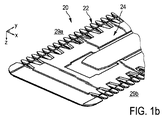
図1a及び1bは、図1に例示的に示されている切断ユニット18のブレードセット20の部分詳細図を示す。ブレードセット20は、静止ブレード22及び可動ブレード24を有する。例として、ブレードセット20は、少なくとも1つの基本的に長手方向に延びる先導(leading)エッジ又は切断エッジ29を有し得る。ブレードセット20は、互いに横方向に離間される2つの切断エッジ29a、29bを有することが好ましい。切断エッジ29a、29bは、横方向Yと基本的に平行である移動方向28に互いに離間され得る。静止ブレード22及び可動ブレード24は、基本的に平らな形状を有し得る。静止ブレード22が可動ブレード24を収容するとともに案内するように構成されることが特に好ましい。言い換えると、静止ブレード22は、可動ブレード24のためのシェル又はケージと見なされ得る。静止ブレード22は、横方向Yに直角な平面の中で見るとき、特に、少なくとも1つの切断エッジにおいて、基本的にU形状である、断面を有し得る。U形状形態は、第1の脚部及び第2の脚部を有し得る。第1の脚部と第2の脚部との間に、可動ブレード24のための案内スロットが画定され得る。可動ブレード24は、静止ブレード22に対する長手方向運動のために、静止ブレード22の中に収容されるとともに案内されることができる。可動ブレード24及び静止ブレード22は、ハサミ様動作で毛を切ることを可能にするそれらの切断エッジにおいてそれぞれの歯を有し得る。静止ブレード22は基本的に、毛を切るとき皮膚を向くそれらの側部において、及び少なくとも部分的に、毛を切るとき皮膚から離れ方を向くそれらの側部において、可動ブレード24を囲む。
FIGS. 1 a and 1 b show a partial detail view of the blade set 20 of the cutting
ブレードセット20をシェービング動作に適切に適合させるために、ブレードセット20の全体的な高さ(又は厚さ)、が、少なくとも、少なくとも1つの切断エッジにおいて、比較的小さいことが好ましい。特に、静止ブレード22の皮膚側部分が比較的小さい厚さを有することが好ましい。一層好ましくは、皮膚を向く静止ブレード部分の厚さは、少なくとも切断エッジにおいて、皮膚から離れる方を向く静止ブレード部分の厚さより著しく小さい。毛切断機器10のための例示的なブレードセット20は、約0.3mmから約0.75mmの範囲の全高又は厚さを有し得る。静止ブレード22の皮膚を向く部分の高さ又は厚さは、少なくとも、少なくとも1つの切断エッジにおいて、約0.04mmから約0.25mmの範囲にあり得る。皮膚から離れる方を向く静止ブレード部分の高さ又は厚さは、約0.08mmから約0.4mmの範囲にあり得る。可動ブレード24の高さ又は厚さは、少なくとも、少なくとも1つの切断エッジにおいて、約0.05mmから約0.5mmの範囲にあり得る。可動ブレード24の高さは基本的に、可動ブレード24のために静止ブレード22によって画定される案内スロットの高さに対応し得る。
In order to properly adapt the blade set 20 to the shaving operation, it is preferred that the overall height (or thickness) of the blade set 20 is relatively small, at least at least at one cutting edge. In particular, it is preferable that the skin side portion of the
ブレードセット20を含む切断ユニット18は、毛切断機器10のハウジングで枢動する又は枢動可能に支持されることが特に好ましい。この目的のために、本開示の原理に従うリンクユニット30が用いられ得る。これに関して、図2、3及び4が参照される。図2は、切断ユニット18を支持するように構成されるリンクユニット30の第1の実施形態の斜視図を示す。リンクユニット30は、図1を参照して、毛切断機器10のブレードセット20とハウジング12との間に配置される4バーリンク機構32を有し得る。さらに図2を参照すると、リンクユニット30はさらに、さらに詳述され、第1のリンクセクション34及び第2のリンクセクション36を有して例示的に示されている。第1のリンクセクション34及び第2のリンクセクション36は、横方向Yに互いに離間され得る。しかし、幾つかの実施形態では、4バーリンク機構32は基本的に単一のリンクセクションを有することが想定され得る。4バーリンク機構32は、Y軸に基本的に平行である、したがって、少なくとも1つの切断エッジ29a、29bに基本的に平行である、(仮想)軸p周りの切断ユニット18の旋回又は枢動運動を可能にするように構成されることができ、これに関して図9も参照されたい。動作の間の、例えば、実際の皮膚輪郭に追従するときの、結果として得られる旋回運動が、図3及び4にそれぞれ両矢印26によって示される。図4は、第1の位置、特にエンド位置を示し得る。図3は、第2の位置、特にスタート位置を示し得る。
It is particularly preferred that the cutting
4バーリンク機構32、又は、幾つかの実施形態では、それらの各リンクセクション34、36は、ベース38を有し得る。図2、3及び4に示された例示的な実施形態によれば、ベース38は、第1のベース部分40a及び第2のベース部分40bを有し得る。ベース部分40a及び40bは、横方向Yに互いに離間され得る。概して、ベース38は、基本的にベース38とハウジング12との間の相対運動が許容されないように、動作中の無視できない遊びなしに毛切断機器10のハウジング12に結合又は接続され得る。4バーリンク機構32又はそれらの各リンクセクション34、36はさらに、第1のアーム42及びそれぞれの第2のアーム44を有し得る。第1のアーム42及び第2のアーム44は、横方向Yに互いに離間され得る。さらに、接続バー46が設けられることができ、そこに、切断ユニット18のブレードセット20が接続又は結合される。4バーリンク機構32のそれぞれの部材は、それぞれのピボット48、50、52、54によって移動可能又は枢動可能に接続され得る。第1のベースピボット48は、第1のアーム42及びそれらのそれぞれのベース部分40aに関するベース38を接続するように配置され得る。第2のベースピボット50は、第2のアーム44及びベース38又はそのそれぞれのベース部分40bに接続するように配置され得る。第1の上部ピボット54は、第1のアーム42及び接続バー46を接続するように構成され得る。同様に、第2の上部ピボット54は、第2のアーム44及び接続バー46を接続するように構成され得る。したがって、上部ピボット52、54は、ベースピボット50、52から垂直方向Zに離間され得る。
The four
ピボット48、50、52、54の、少なくとも1つ、より好ましくは、それぞれは、リビングヒンジとして構成され得る。特に、ピボット48、50、52、54は、フィルムヒンジとして構成され得る。言い換えると、それらの間に置かれたピボット48、50、52、54を含む、ベース部分40a、40bを含むベース38、第1のアーム42、第2のアーム44及び接続バー46は、単一ピースとして一体に製造されることができ、図3及び4も参照されたい。例えば、4バーリンク機構32は、単一の射出成形された部品として形成され得る。図2に最も良く見ることができるように、第1のリンクセクション34及び第2のリンクセクション36もまた一体に形成され得る。しかし、代替では、第1のリンクセクション34及び第2のリンクセクション36のそれぞれは、別個の一体成形された部品として形成され得る。
At least one, and more preferably, each of the
図2からさらに見ることができるように、接続バー46はさらに、少なくとも1つの側部アーム56を、特にブレードセット20に結合され得る第1の側部アーム56a及び第2の側部アーム56bを有し得る。側部アーム56a、56bのそれぞれは、接続バー46から外向きに延び得る。少なくとも1つの側部アーム56a、56bは、接続バー46に及びブレードセット20に対して傾斜し得る。これに関して、本明細書で論じられ且つ記載されるように、構造的な特徴及び関係が、別段の指示がない限り、例えば、図2、5及び9に示されるように、リンクユニット30の中立位置(又は中心にされた位置)を典型的に示し得ることは言うまでもない。
As can further be seen from FIG. 2, the
図2はさらに、相対リミット停止装置と見なされ得るオプションのリミット停止装置を示す。リミット停止装置は、少なくとも1つの接触タブ58、60を有する。図2から見ることができるように、2つの対応する接触タブ58、60が設けられ得る。第1の接触タブ58は、第1のアーム42に設けられ、そこから突出する。第2の接触タブ60は、接続バー46に、又はより具体的には、横方向に突出する方法でその第1の側部アーム56aに設けられ得る。接触タブ58、60のそれぞれは、対向する構成要素のそれぞれの接触面と協働し得る。接触タブ58、60は、第1の上部ピボット52を定めるヒンジによって定められるピボット軸周りの接続バー46と第1のアーム42との間の相対ピボット運動を制限するように、協働し得る。第1の接触タブ58及び第2の接触タブ60が互いに接触又は当接するとき、接触タブ58及び接触タブ60によって定められる限度を超える4バーリンク機構32の一般的な運動も基本的に妨げられる。この方法では、ピボット48、50、52、54における過度な歪が回避されることができるので、4バーリンク機構32の過度な運動を妨げることは有益である。さらに、切断ユニット18は、動作中の皮膚刺激のリスク又は皮膚を切るリスクさえ増加させるかもしれない、望ましくない向き、例えば、過大な旋回角度を取ることを防ぐことができる。好ましくは、接触タブ58、60の少なくとも2つのペアが、リンク機構32に設けられる(図2に明示的に示されていない)。
FIG. 2 further illustrates an optional limit stop device that may be considered a relative limit stop device. The limit stop device has at least one
特に図5を参照すると、4バーリンク機構32aの代替実施形態が、示されるとともにさらに詳述される。図2に示される4バーリンク機構32と同様に、図5に示される4バーリンク機構32aは、それぞれの第1及び第2のベースピボット48、50並びに第1及び第2の上部ピボット52、54によって結合される、ベース38、第1のアーム42、第2のアーム44及び接続バー46を有する。図2に示された実施形態と対照的に、ベース38は、第1のベースピボット48及び第2のベースピボット50を連続的に(又は直接)接続する一体構成要素として形成される。図5に例示された4バーリンク機構32aは、閉鎖構成又は閉鎖チェーンとして構成される。対照的に、図2に例示された4バーリンク機構32は、開放構成又は開放チェーンとして形成される。さらに図5を参照して、4バーリンク機構32aがさらに詳述される。端部停止装置が設けられ、機構32aの第1のアーム側に接触タブ58a、60aの第1のペアを追加する。端部停止装置はさらに、機構32aの第2のアーム側に配置された接触タブ58b、60bの第2のペアをさらに有する。したがって、4バーリンク機構32aの枢動運動は、スタート位置とエンド位置との間で前に動くとき及び後ろに動くときの両方で、制限されることができる。
With particular reference to FIG. 5, an alternative embodiment of a four
1つの実施形態では、図5に示される4バーリンク機構32aは、特に、3次元ニアネットシェイプにされたモールド部品として、射出成形されることが特に好ましい。したがって、4バーリンク機構32a及びそれぞれのリンクユニットは、成形プロセスの後に容易に設置され得る。高価な仕上げ加工ステップ、アライメントステップ及び努力を要する組立ステップがこの方法で止められることができる。
In one embodiment, it is particularly preferred that the 4-
しかし、幾つかの代替実施形態では、他の製造アプローチが追及され得る。図6aに最も良く示されるように、4バーリンク機構32の前駆体又は中間部品が、概して平らな中間構成62として、形成、特に射出成形され得る。中間構成62は、少なくとも1つの薄くされた凹所64を有し得る。少なくとも1つの薄くされた凹所64は、後に、4バーリンク機構32のそれぞれのピボット48、50、52、54を画定し得る。図6aの最初に基本的に平らな中間構成62は、図6bに進んだ製造段階で示されている。中間構成62を変形させる、特に曲げることによって、4バーリンク機構32の基本的に3次元形状が達成され得る。図6bはさらに、4バーリンク機構32の例示の開放チェーン構成を示す。
However, in some alternative embodiments, other manufacturing approaches may be pursued. As best shown in FIG. 6a, the precursor or intermediate piece of the four-
図7及び図8は、リンクユニット30aの他の代替実施形態を示す。リンクユニット30aは、図1乃至6bに示された実施形態の原理の少なくとも幾つかに従って基本的に形成された4バーリンク機構32bを有し得る。しかし、4バーリンク機構32bは、接続バー46が、又は言い換えると、その上部結合部分が、切断ユニット18自体によって形成され得るという点でそれらと異なり得る。言い換えると、4バーリンク機構32bは、第1の上部ピボット52を介して第1のアーム42に結合された第1の接続アーム66a及び第2の上部ピボット54を介して第2のアーム44に結合された第2の接続アーム66bを有し得る。第1の接続アーム66a及び第2の接続アーム66bは、切断ユニット18を介して互いに(仲介して)固定して接続される。より具体的には、第1の接続アーム66a及び第2の接続アーム66bは、基本的に相対運動を妨げられる。この実施形態はさらに、4バーリンク機構32bを2つの横方向に離間した部品に分割することを可能にし得る。
7 and 8 show another alternative embodiment of the
リンクユニット30aはさらに、絶対端部停止装置を有する。端部停止装置は、端部停止サポート68を有し得る。端部停止サポート68は、少なくとも1つの端部停止ビーム70、72を有し得る。好ましくは、外側端部停止ビーム70の第1のペアが、設けられる。それに応じて、内側端部停止ビーム72の第2のペアが、設けられる。端部停止ビーム70は、それぞれの旋回又は枢動運動を制限するように、接続バー46と直接又は間接的に協働するように配置され得る。端部停止ビーム72は、それぞれの旋回又は枢動運動を制限するように、第1のアーム42及び第2のアーム44の少なくとも一方と協働するように構成され得る。少なくとも1つの端面74a、74bが、端部ビーム70に設けられ得る。少なくとも1つの端面76a、76bが、端部ビーム72に設けられ得る。
The
端部ビーム70の少なくとも1つの端面74a、74bは、接続バー46に付随するそれぞれの接触面と接触又は当接するように配置され得る。端部ビーム72の少なくとも1つの端面76a、76bは、第1のアーム42及び第2のアーム44の少なくとも一方で対応する接触面と接触又は当接するように配置され得る。図7及び8に示された絶対端部停止装置は、過度な運動が、4バーリンク機構32bの可動構成要素から分離している外部構成要素によって制限されることができる限りにおいて、有益であり得る。図7及び図8の両方は、スタート位置における4バーリンク機構32bを示している。
At least one
特に図9及び図10を参照すると、リンクユニット30bのさらに他の例示的な実施形態が、例示されている。リンクユニット30bは、図2に示された4バーリンク機構32の実施形態に基本的に対応し得る4バーリンク機構32を有し得る。それを別として、リンクユニット30bはさらに、少なくとも1つの付勢要素80a、80bを有する。特に、第1のアーム42に関連付けられる第1の付勢要素80aが設けられ得る。第1の付勢要素80aは、第1のアーム42を第1の付勢方向82aに付勢するように構成され得る。幾つかの実施形態では、第2のアーム44に関連付けられる第2の(サポート)付勢要素80bが設けられ得る。第2の付勢要素80bは、第2のアーム44を第2の付勢方向82bに付勢するように構成され得る。第1の付勢方向82a及び第2の付勢方向82b、付勢要素80a、80bは、第1のアーム42及び第2のアーム44を反対方向82a、82bに基本的に付勢し得る。付勢要素80aは、4バーリンク機構32が、動作しているとき、枢動した後図8に示されるスタート位置に戻ることを確実にし得る。付勢要素80aは、リンク機構32の基本的に遊び無しの支持を確実にし得る。
With particular reference to FIGS. 9 and 10, yet another exemplary embodiment of the link unit 30b is illustrated. The link unit 30b may have a 4
図10から概略的に見ることができるように、少なくとも1つの付勢要素80a、80bは、例えば、トーションバースプリング80として構成され得る。トーションバースプリング80は、トーションバー84並びに、トーションバー84のそれぞれの端部に設けられた第1の脚部86及び第2の脚部88を有し得る。第1の付勢要素80a及び第2の付勢要素80bの同様の配置の側面図が、図9に示されている。
As can be seen schematically from FIG. 10, the at least one biasing
特に、トーションバースプリング80のトーションバー84は、ベース38に取り付けられることができる。さらに、第1の脚部86は、トーションバー84による過度な発見に関する望ましくない回転に抗してベース38に固定され得る。トーションバースプリング80は、トーションバー84をベース38に取り付け、第1の脚部86をベース38に固定すると、第2の脚部88が第1のアーム42に対して付勢することができるように、設計され且つ形成され得る。
In particular, the
図9から最も良く見ることができるように、少なくとも1つの付勢要素80a、80bは、4バーリンク機構32のそれぞれの第1のアーム42及び第2のアーム44の近傍に又は近接して配置され得る。したがって、リンク機構32の中心部分は、十分な設計空間が、切断ユニット18のブレードセット20の可動ブレードを駆動するために設けられるように、空いている且つ妨害が無い状態に保たれることができる。リンクセクション34、36(図2を参照)のそれぞれが、リンク機構をスタート位置に付勢するように構成されるそれぞれの第1の付勢要素80aに関連付けられることがさらに想定され得る。
As can best be seen from FIG. 9, the at least one biasing
図9からさらに見ることができるように、4バーリンク機構32は、少なくとも幾つかの好適な実施形態において、定められる結果的に得られる仮想ピボット軸pが少なくとも1つの歯付き切断エッジ29a、29bと基本的に平行であるように設計されることができ、図1a及び1bも参照されたい。さらに、4バーリンク機構32は、少なくとも図9に示された中立位置において、皮膚に向かう垂直方向Zにブレードセット20の皮膚を向く側からオフセットされるピボット軸pを含むように構成され得る。皮膚を向く側は、本開示の目的のために、上面90とも称され得る。対応するオフセット寸法loが、図9に示されている。言い換えると、4バーリンク機構32の(仮想)ピボット軸pは、幾つかの実施形態において、皮膚「の中に」移され得る。これはシェービング性能をさらに向上させ得る。このような構成は、従来の実際の構造的ピボット装置で達成することができない。しかし、幾つかの代替実施形態では、仮想ピボットpは、皮膚レベルの上に、すなわち、上面90のレベルの下に、配置され得る。ピボットオフセット寸法loは、少なくとも中立位置において、約−2.0mmから約+5.0mmの範囲に、好ましくは、約−1.0mmから約+2.0mmの範囲に、より好ましくは、約+0.25mmから約+0.75mmの範囲にあることが好ましい。本明細書で使用されるとき、+(プラス)は、ピボット軸pが上面90のレベルの上に位置する、すなわち、皮膚「の中に」移される、配置を示す。対照的に、−(マイナス)は、ピボット軸pが上面90のレベルの下に、すなわち皮膚の上に、位置する、配置を示す。
As can be further seen from FIG. 9, the 4-
特に図11を参照すると、毛切断機器10の毛切断ユニット及びハウジング12(図1も参照)を枢動可能に接続するためのリンクユニット30cの他の代替実施形態が、示されるとともに、さらに詳述される。リンクユニット30cは、少なくとも1つのピボットジョイントを備える4バーリンク機構32aを有し、この少なくとも1つのピボットジョイントは、例えば少なくとも1つのそれぞれの別個のピボットシートを介して、2つの結合されることになる要素と協働するピボットピンを有し得る。ピボットピンは、少なくとも1つのピボットシートで受けられることができる。ピボットピン及びピボットシートは、ピボットベアリングを定めるように、協働し得る。
With particular reference to FIG. 11, another alternative embodiment of the
4バーリンク機構32aは、ベース38a、第1のアーム42a、第2のアーム44a、及び接続バー46aを有する。ベース38aは、そのベース端部において、第1のアーム42aと第2のアーム44aとの間に置かれる。接続バー46aは、その上部端部において、第1のアーム42aと第2のアーム44aとの間に置かれる。ベース38aと第1のアーム42aとの間に、第1のベースピボット又はベースピボットジョイント48aが設けられ得る。ベース38aと第2のアーム44aとの間に、第2のベースピボット又はベースピボットジョイント50aが設けられ得る。接続バー46aと第1のアーム42aとの間に、第1の上部ピボット又は上部ピボットジョイント52aが設けられ得る。接続バー46aと第2のアーム44aとの間に、第2の上部ピボット又は上部ピボットジョイント54aが設けられ得る。ピボット48a、50a、52a、54aの少なくとも1つがリビングヒンジとして設けられ得ることは言うまでもない。しかし、図11に示された実施形態に関連して、ピボット48a、50a、52a、54aのそれぞれが、両方のそれぞれの結合されることになる要素と一体に形成されていない少なくとも1つの別個の部品を有する組立てられたピボットジョイントであることが好ましくなり得る。
The 4-
図11の4バーリンク機構32aはまた、図11に示された中立位置(又は中央位置)において、上で論じられたような、ピボットオフセット寸法loだけブレードセット20の上面90からオフセットされる仮想ピボット軸pを定め得る。
The 4-
本発明の例示的な実施形態が、部分的に添付の図面を参照して、上に記載されているが、本発明はこれらの実施形態に限定されないことが理解されるべきである。開示された実施形態に対する変形形態は、当業者によって、図面、明細書、及び添付の請求項の検討から、理解されるとともに、請求項に記載された発明を実施する際に実施されるであろう。本明細書全体を通して「1つの実施形態」又は「一実施形態」との言及は、実施形態に関連して記載されている特定の特徴、構造又は特性が、本開示による、静止ブレード、ブレードセット等の少なくとも1つの実施形態に含まれることを意味する。したがって、本明細書全体に亘って様々な場所において出現する「1つの実施形態では」又は「一実施形態では」との表現は、必ずしも全て同じ実施形態を指しているわけではない。さらに、1又は複数の実施形態の特定の特徴、構造、又は特性は、新しい、明示的に記載されていない実施形態を形成するために、任意の適切な態様で組み合わされ得ることが留意される。 While exemplary embodiments of the present invention have been described above, in part with reference to the accompanying drawings, it should be understood that the present invention is not limited to these embodiments. Variations to the disclosed embodiments will be understood by those skilled in the art from consideration of the drawings, specification, and appended claims, and implemented in practicing the claimed invention. Let's go. Throughout this specification, reference to “one embodiment” or “one embodiment” refers to a particular feature, structure or characteristic described in connection with the embodiment, in accordance with the present disclosure, a stationary blade, a blade set It is meant to be included in at least one embodiment. Thus, the phrases “in one embodiment” or “in one embodiment” appearing in various places throughout this specification are not necessarily all referring to the same embodiment. Furthermore, it is noted that the particular features, structures, or characteristics of one or more embodiments may be combined in any suitable manner to form new, not explicitly described embodiments. .
請求項において、用語“有する”は他の要素又はステップを除外せず、不定冠詞“a”又は“an”は複数を除外しない。単一の要素又は他のユニットは、請求項に記載の幾つかの項目の機能を満たし得る。特定の手段が相互に異なる従属項に記載されているという単なる事実は、これらの手段の組み合わせが有利に使用できないことを示すものではない。 In the claims, the term “comprising” does not exclude other elements or steps, and the indefinite article “a” or “an” does not exclude a plurality. A single element or other unit may fulfill the functions of several items recited in the claims. The mere fact that certain measures are recited in mutually different dependent claims does not indicate that a combination of these measured cannot be used to advantage.
請求項における如何なる参照符号もその範囲を限定するものとして解釈されるべきではない。 Any reference signs in the claims should not be construed as limiting the scope.
Claims (17)
前記切断ユニットは、静止ブレード、可動ブレード及び少なくとも1つの基本的に長手方向に延びる切断エッジを有するブレードセットを有し、前記静止ブレードは、前記静止ブレードに対する長手方向運動のために前記可動ブレードを収容するとともに案内するように構成され、
前記静止ブレードは、横方向に対して直角な平面視で、前記少なくとも1つの切断エッジにおいて、U形状である断面を有し、前記U形状の形態は、第1の脚部及び第2の脚部を有し、前記可動ブレードのための案内スロットが、前記第1の脚部と前記第2の脚部との間に設けられ、前記静止ブレードは、前記可動ブレードを、毛を切るとき皮膚を向くその側部で、及び、少なくとも部分的に、毛を切るとき前記皮膚から離れる方を向くその側部で、基本的に囲み、
前記リンクユニットは、4バーリンク機構を有し、
前記4バーリンク機構は、第1のアーム及び前記第1のアームの反対側の第2のアームを有し、前記第1のアームは、ベースに結合される第1のベースピボットを有し、前記第2のアームは、前記ベースに結合される第2のベースピボットを有し、前記第1のベースピボット及び前記第2のベースピボットは、定められた距離を置いて前記ベースに配置され、前記第1のアームはさらに、接続バーに結合される第1の上部ピボットを有し、前記第2のアームはさらに、前記接続バーに結合される第2の上部ピボットを有し、前記接続バーは、動作中、前記切断ユニットが前記リンク機構によって枢動可能に支持されるように、前記切断ユニットに結合されるよう構成され、
前記切断ユニット及び前記リンクユニットは、前記4バーリンク機構の望ましくない運動を妨げるための少なくとも1つの端部停止要素をさらに有し、
前記少なくとも1つの端部停止要素は、前記第1のアーム、前記第2のアーム及び前記接続バーの少なくとも1つにおいて、少なくとも1つの突出接触タブ、並びに前記第1のアーム、前記第2のアーム及び前記接続バーの他の1つにおいて、少なくとも1つの対応する接触面を有し、前記少なくとも1つの突出接触タブ及び前記少なくとも1つの対応する接触面は、前記第1及び前記第2のアームと前記接続バーとの間の最大相対回転を定めるようになる、
切断ユニット及びリンクユニット。 A cutting unit and a link unit for a hair cutting device, wherein the cutting unit is configured to be coupled to a housing of the hair cutting device by the link unit, the cutting unit comprising a stationary blade, a movable blade and at least A blade set having one essentially longitudinally extending cutting edge, the stationary blade configured to receive and guide the movable blade for longitudinal movement relative to the stationary blade;
The stationary blade has a U-shaped cross section at the at least one cutting edge in a plan view perpendicular to a lateral direction, and the U-shaped form includes a first leg and a second leg. A guide slot for the movable blade is provided between the first leg and the second leg, and the stationary blade causes the movable blade to cut skin when hair is cut. Basically with its side facing towards and at least partly with its side facing away from said skin when cutting hair,
The link unit has a 4-bar link mechanism,
The 4-bar link mechanism has a first arm and a second arm opposite to the first arm, and the first arm has a first base pivot coupled to a base; The second arm has a second base pivot coupled to the base, and the first base pivot and the second base pivot are disposed on the base at a predetermined distance; The first arm further includes a first upper pivot coupled to the connection bar, and the second arm further includes a second upper pivot coupled to the connection bar. Is configured to be coupled to the cutting unit such that, in operation, the cutting unit is pivotally supported by the linkage mechanism;
The cutting unit and the link unit further comprise at least one end stop element for preventing undesired movement of the 4-bar linkage;
The at least one end stop element includes at least one protruding contact tab and at least one of the first arm, the second arm in at least one of the first arm, the second arm, and the connection bar. And the other one of the connecting bars has at least one corresponding contact surface, the at least one protruding contact tab and the at least one corresponding contact surface being connected to the first and second arms. To determine the maximum relative rotation with the connection bar,
Cutting unit and link unit.
請求項1に記載の切断ユニット及びリンクユニット。 The 4-bar linkage defines a virtual pivot for the cutting unit, the virtual pivot having a virtual pivot axis that is substantially parallel to the cutting edge of the cutting unit;
The cutting unit and the link unit according to claim 1.
請求項2に記載の切断ユニット及びリンクユニット。 The pivot shaft is located near the top surface of the cutting unit that, when attached, faces away from the housing of the hair-cutting device, and the pivot shaft is in the neutral position of the 4-bar linkage mechanism from the top surface. Offset by a pivot offset dimension in the range between -2.0 mm and +5.0 mm below and above the height of the upper surface,
The cutting unit and the link unit according to claim 2.
請求項2に記載の切断ユニット及びリンクユニット。 The pivot shaft is located near the top surface of the cutting unit that, when attached, faces away from the housing of the hair-cutting device, and the pivot shaft is in the neutral position of the 4-bar linkage mechanism from the top surface. Offset by a pivot offset dimension in the range between -1.0 mm and +2.0 mm below and above the height of the top surface,
The cutting unit and the link unit according to claim 2.
請求項2に記載の切断ユニット及びリンクユニット。 The pivot shaft is located near the top surface of the cutting unit that, when attached, faces away from the housing of the hair-cutting device, and the pivot shaft is in the neutral position of the 4-bar linkage mechanism from the top surface. Offset by a pivot offset dimension in the range between +0.25 mm and +0.75 mm below and above the height of the top surface,
The cutting unit and the link unit according to claim 2.
請求項1に記載の切断ユニット及びリンクユニット。 At least the first arm, the second arm and the connection bar and their respective base pivot and upper pivot are integrally formed as a single piece,
The cutting unit and the link unit according to claim 1.
請求項6に記載の切断ユニット及びリンクユニット。 All pivots of the 4-bar link mechanism are configured as living hinges,
The cutting unit and the link unit according to claim 6 .
請求項1に記載の切断ユニット及びリンクユニット。 The 4-bar link mechanism is an integrally formed injection-molded plastic part.
The cutting unit and the link unit according to claim 1.
請求項1に記載の切断ユニット及びリンクユニット。 The 4-bar link mechanism is a molded part having a three-dimensional near net shape, and the hinge forming the pivot is basically not biased when the link mechanism is in a neutral position.
The cutting unit and the link unit according to claim 1.
請求項1に記載の切断ユニット及びリンクユニット。 The length of the base defined by the distance between the first base pivot and the second base pivot is defined by the distance between the first upper pivot and the second upper pivot. Greater than the length of the connection bar,
The cutting unit and the link unit according to claim 1.
請求項1に記載の切断ユニット及びリンクユニット。 And further comprising at least one biasing element for biasing the 4-bar link mechanism to a predetermined start position.
The cutting unit and the link unit according to claim 1.
請求項11に記載の切断ユニット及びリンクユニット。 The at least one biasing element is a torsion bar spring disposed on the base, the torsion bar spring having a torsion bar pivotally received on the base, the torsion bar comprising a first torsion bar Located between a leg and a second leg, the first leg is coupled to the base, and the second leg is coupled to one of the first arm and the second arm. To be
The cutting unit and the link unit according to claim 11.
請求項1に記載の切断ユニット及びリンクユニット。 The at least one end stop element cooperates with at least one biasing element, and the resulting biasing force causes the four bar linkage to act against at least one of the at least one end stop element. Energize,
The cutting unit and the link unit according to claim 1.
請求項1に記載の切断ユニット及びリンクユニット。 The at least one end stop element is connected to the base and arranged to limit movement of the cutting unit;
The cutting unit and the link unit according to claim 1.
請求項1に記載の切断ユニット及びリンクユニット。 The at least one end stop element is disposed on an end stop support having at least one end stop beam, the at least one end stop beam having at least one end surface, and the at least one end surface. Abuts the bottom side of the cutting unit to limit movement of the cutting unit;
The cutting unit and the link unit according to claim 1.
請求項1に記載の切断ユニット及びリンクユニット。 The at least one end stop element is coupled to the base and arranged to limit at least one movement of the first arm, the second arm, and the connection bar;
The cutting unit and the link unit according to claim 1.
前記4バーリンク機構は、第1のアーム及び前記第1のアームの反対側の第2のアームを有し、前記第1のアームは、ベースに結合される第1のベースピボットを有し、前記第2のアームは、前記ベースに結合される第2のベースピボットを有し、前記第1のベースピボット及び前記第2のベースピボットは、定められた距離を置いて前記ベースに配置され、前記第1のアームはさらに、接続バーに結合される第1の上部ピボットを有し、前記第2のアームはさらに、前記接続バーに結合される第2の上部ピボットを有し、前記接続バーは、動作中、前記切断ユニットが前記リンク機構によって枢動可能に支持されるように、前記切断ユニットに結合されるよう構成され、
前記切断ユニット及び前記リンクユニットは、前記4バーリンク機構の望ましくない運動を妨げるための少なくとも1つの端部停止要素をさらに有し、
前記少なくとも1つの端部停止要素は、前記第1のアーム、前記第2のアーム及び前記接続バーの少なくとも1つにおいて、少なくとも1つの突出接触タブ、並びに前記第1のアーム、前記第2のアーム及び前記接続バーの他の1つにおいて、少なくとも1つの対応する接触面を有し、前記少なくとも1つの突出接触タブ及び前記少なくとも1つの対応する接触面は、前記第1及び前記第2のアームと前記接続バーとの間の最大相対回転を定めるようになる、
毛切断機器。 Housing containing motor, a cutting unit, as well as a link unit, for coupling the cutting unit and the housing, a hair-cutting apparatus, wherein the link unit includes a four-bar linkage,
The 4-bar link mechanism has a first arm and a second arm opposite to the first arm, and the first arm has a first base pivot coupled to a base; The second arm has a second base pivot coupled to the base, and the first base pivot and the second base pivot are disposed on the base at a predetermined distance; The first arm further includes a first upper pivot coupled to the connection bar, and the second arm further includes a second upper pivot coupled to the connection bar. Is configured to be coupled to the cutting unit such that, in operation, the cutting unit is pivotally supported by the linkage mechanism;
The cutting unit and the link unit further comprise at least one end stop element for preventing undesired movement of the 4-bar linkage;
The at least one end stop element includes at least one protruding contact tab and at least one of the first arm, the second arm in at least one of the first arm, the second arm, and the connection bar. And the other one of the connecting bars has at least one corresponding contact surface, the at least one protruding contact tab and the at least one corresponding contact surface being connected to the first and second arms. To determine the maximum relative rotation with the connection bar,
Hair cutting equipment.
Applications Claiming Priority (3)
| Application Number | Priority Date | Filing Date | Title |
|---|---|---|---|
| EP13193972.0 | 2013-11-22 | ||
| EP13193972.0A EP2875915B1 (en) | 2013-11-22 | 2013-11-22 | Linkage unit and hair cutting appliance |
| PCT/EP2014/073882 WO2015074882A1 (en) | 2013-11-22 | 2014-11-06 | Linkage unit and hair cutting appliance |
Related Child Applications (1)
| Application Number | Title | Priority Date | Filing Date |
|---|---|---|---|
| JP2018060097A Division JP6564099B2 (en) | 2013-11-22 | 2018-03-27 | Link unit and hair cutting device |
Publications (3)
| Publication Number | Publication Date |
|---|---|
| JP2016537132A JP2016537132A (en) | 2016-12-01 |
| JP2016537132A5 JP2016537132A5 (en) | 2018-02-22 |
| JP6316426B2 true JP6316426B2 (en) | 2018-04-25 |
Family
ID=49680821
Family Applications (2)
| Application Number | Title | Priority Date | Filing Date |
|---|---|---|---|
| JP2016533207A Active JP6316426B2 (en) | 2013-11-22 | 2014-11-06 | Link unit and hair cutting device |
| JP2018060097A Active JP6564099B2 (en) | 2013-11-22 | 2018-03-27 | Link unit and hair cutting device |
Family Applications After (1)
| Application Number | Title | Priority Date | Filing Date |
|---|---|---|---|
| JP2018060097A Active JP6564099B2 (en) | 2013-11-22 | 2018-03-27 | Link unit and hair cutting device |
Country Status (6)
| Country | Link |
|---|---|
| US (1) | US9925675B2 (en) |
| EP (2) | EP2875915B1 (en) |
| JP (2) | JP6316426B2 (en) |
| CN (2) | CN204585267U (en) |
| RU (1) | RU2674052C1 (en) |
| WO (1) | WO2015074882A1 (en) |
Families Citing this family (36)
| Publication number | Priority date | Publication date | Assignee | Title |
|---|---|---|---|---|
| US9486930B2 (en) * | 2012-09-27 | 2016-11-08 | Shavelogic, Inc. | Shaving systems |
| EP2875916B2 (en) | 2013-11-22 | 2021-09-29 | Koninklijke Philips N.V. | Mounting unit and hair cutting appliance |
| EP2875915B1 (en) * | 2013-11-22 | 2019-05-22 | Koninklijke Philips N.V. | Linkage unit and hair cutting appliance |
| EP3300854B1 (en) | 2016-09-28 | 2020-06-10 | Braun GmbH | Electric shaver |
| EP3305485B1 (en) * | 2016-09-28 | 2019-07-03 | Braun GmbH | Electric shaver |
| US10443649B2 (en) * | 2017-01-24 | 2019-10-15 | Raytheon Company | Flexural pivot |
| EP3388206A1 (en) | 2017-04-14 | 2018-10-17 | Koninklijke Philips N.V. | Attachment comb, cutting head and hair cutting appliance |
| CN208342890U (en) | 2017-05-15 | 2019-01-08 | A·库班尼 | Hair cutting device |
| WO2018223683A1 (en) * | 2017-06-05 | 2018-12-13 | 黄勇辉 | Novel electric hair clipper |
| EP3450119A1 (en) | 2017-08-30 | 2019-03-06 | Koninklijke Philips N.V. | Processing head for a hair cutting appliance and combined blade unit |
| USD952946S1 (en) | 2017-09-01 | 2022-05-24 | Church & Dwight Co., Inc. | Hair removal device |
| EP3546147B1 (en) * | 2018-03-29 | 2023-05-24 | Braun GmbH | Hair removal device |
| US11123888B2 (en) | 2018-03-30 | 2021-09-21 | The Gillette Company Llc | Razor handle with a pivoting portion |
| EP3705245B1 (en) | 2018-03-30 | 2021-12-15 | The Gillette Company LLC | Shaving razor handle |
| JP2021517492A (en) | 2018-03-30 | 2021-07-26 | ザ ジレット カンパニー リミテッド ライアビリティ カンパニーThe Gillette Company Llc | Razor handle with pivot part |
| JP2021517043A (en) | 2018-03-30 | 2021-07-15 | ザ ジレット カンパニー リミテッド ライアビリティ カンパニーThe Gillette Company Llc | Razor handle with pivot part |
| BR112020020123A2 (en) | 2018-03-30 | 2021-01-26 | The Gillette Company Llc | shaver or shaving handle with a pivoting portion |
| USD874061S1 (en) | 2018-03-30 | 2020-01-28 | The Gillette Company Llc | Shaving razor cartridge |
| JP7090727B2 (en) | 2018-03-30 | 2022-06-24 | ザ ジレット カンパニー リミテッド ライアビリティ カンパニー | Razor handle with pivot part |
| EP3774224A1 (en) | 2018-03-30 | 2021-02-17 | The Gillette Company LLC | Razor handle with a pivoting portion |
| JP2021516136A (en) | 2018-03-30 | 2021-07-01 | ザ ジレット カンパニー リミテッド ライアビリティ カンパニーThe Gillette Company Llc | Razor handle with movable members |
| US11607820B2 (en) | 2018-03-30 | 2023-03-21 | The Gillette Company Llc | Razor handle with movable members |
| CN111819050B (en) | 2018-03-30 | 2022-10-04 | 吉列有限责任公司 | Razor handle with movable member |
| CN209732902U (en) * | 2018-12-07 | 2019-12-06 | 飞利浦(中国)投资有限公司 | hair appliance |
| USD925830S1 (en) | 2019-07-19 | 2021-07-20 | Church & Dwight Co., Inc. | Head assembly for hair removal apparatus |
| USD914977S1 (en) | 2019-07-19 | 2021-03-30 | Church & Dwight Co., Inc. | Handle for hair removal apparatus |
| USD936899S1 (en) | 2019-10-18 | 2021-11-23 | Church & Dwight Co., Inc. | Hair removal apparatus |
| USD914978S1 (en) | 2019-10-18 | 2021-03-30 | Church & Dwight Co., Inc. | Hair removal apparatus |
| USD942687S1 (en) | 2019-11-18 | 2022-02-01 | Church & Dwight Co., Inc. | Articulating blade assembly for hair removal device |
| USD940958S1 (en) | 2019-11-18 | 2022-01-11 | Church & Dwight Co., Inc. | Articulating blade assembly for hair removal device |
| EP3907044A1 (en) | 2020-05-08 | 2021-11-10 | Braun GmbH | Electric beard trimmer |
| EP3907049B1 (en) | 2020-05-08 | 2023-03-22 | Braun GmbH | Electric beard trimmer |
| EP3978211A1 (en) | 2020-10-01 | 2022-04-06 | Koninklijke Philips N.V. | A mounting assembly and a hair cutting appliance |
| EP4112247A1 (en) * | 2021-07-02 | 2023-01-04 | Koninklijke Philips N.V. | A mounting assembly |
| EP4112246A1 (en) | 2021-07-02 | 2023-01-04 | Koninklijke Philips N.V. | Mounting assembly for a hair cutting appliance |
| EP4197720A1 (en) * | 2021-12-20 | 2023-06-21 | Babyliss Faco SRL | Beard trimmer with damping system for the cutting unit |
Family Cites Families (31)
| Publication number | Priority date | Publication date | Assignee | Title |
|---|---|---|---|---|
| US2102529A (en) * | 1935-02-07 | 1937-12-14 | Clipshave Inc | Hair clipper |
| US2151965A (en) * | 1937-04-05 | 1939-03-28 | Clipshave Inc | Hair clipper |
| US2290326A (en) * | 1939-11-21 | 1942-07-21 | Gillette Safety Razor Co | Dry shaving appliance |
| GB8626631D0 (en) * | 1986-11-07 | 1986-12-10 | Gillette Co | Dry shavers |
| US5611145A (en) * | 1991-12-20 | 1997-03-18 | Wetzel; Matthias | Dry-shaving apparatus |
| DE4244164C2 (en) * | 1992-12-24 | 1995-09-07 | Braun Ag | Dry shaver with a pivoting long hair trimmer |
| DE4413352C1 (en) * | 1994-04-18 | 1995-05-04 | Braun Ag | Method for producing a cutter for a cutting device of an electric razor or beard trimmer |
| US5787593A (en) * | 1995-11-29 | 1998-08-04 | Warner-Lambert Company | Pivoting shaving system |
| US5661907A (en) | 1996-04-10 | 1997-09-02 | The Gillette Company | Razor blade assembly |
| US6308416B1 (en) | 1998-12-31 | 2001-10-30 | The Gillette Company | Surface conforming shaving razor and handle therefor |
| US6317982B1 (en) * | 1999-10-22 | 2001-11-20 | Remington Corporation L.L.C. | Shaving system and adjustable trimmers therefor |
| CN2423078Y (en) * | 2000-05-23 | 2001-03-14 | 木大实业股份有限公司 | Hair shaver |
| US6555031B2 (en) | 2000-06-19 | 2003-04-29 | Corning Incorporated | Process for producing silicon carbide bodies |
| AU2003212586A1 (en) * | 2002-05-16 | 2003-12-02 | Warner-Lambert Company Llc | Razor cartridge mounting structure |
| US7137205B2 (en) * | 2002-10-01 | 2006-11-21 | The Gillette Company | Linkage mechanism providing a virtual pivot axis for razor apparatus with pivotal head |
| DE60204780T2 (en) * | 2002-10-01 | 2006-05-18 | The Gillette Co., Boston | Articulated gear with virtual swivel axis for hair removal device with oscillating head |
| JP2004216067A (en) * | 2003-01-17 | 2004-08-05 | Matsushita Electric Works Ltd | Head swing mechanism for hair cutter |
| JP3972903B2 (en) | 2003-12-26 | 2007-09-05 | 松下電工株式会社 | Electric razor |
| JP2006042898A (en) | 2004-07-30 | 2006-02-16 | Matsushita Electric Works Ltd | Electric shaver |
| DE102006030947A1 (en) * | 2006-07-05 | 2008-01-10 | Braun Gmbh | Electric dry shaver |
| DE102008031132A1 (en) * | 2008-07-01 | 2010-01-07 | Braun Gmbh | Small electrical appliance for removing hair |
| JP4955711B2 (en) * | 2009-01-15 | 2012-06-20 | パナソニック株式会社 | Electric razor |
| JP4988777B2 (en) * | 2009-01-15 | 2012-08-01 | パナソニック株式会社 | Electric razor |
| CN202200323U (en) * | 2011-08-29 | 2012-04-25 | 珠海新秀丽家居用品有限公司 | Personal care hair shears |
| RU113688U1 (en) * | 2011-11-30 | 2012-02-27 | Общество С Ограниченной Ответственностью "Хитэк-Груп" | HAIR CLIPPER |
| US20130160306A1 (en) | 2011-12-22 | 2013-06-27 | Daren Mark Howell | Linkage mechanism producing a virtual pivot axis for a razor |
| CA3021116C (en) | 2012-04-03 | 2020-08-18 | Koninklijke Philips N.V. | Blade set for hair cutting appliance and method for its manufacture |
| CN202846561U (en) * | 2012-08-20 | 2013-04-03 | 宁波邦首电器有限公司 | Shearer with double-sided knife |
| EP2875915B1 (en) * | 2013-11-22 | 2019-05-22 | Koninklijke Philips N.V. | Linkage unit and hair cutting appliance |
| EP2875916B2 (en) * | 2013-11-22 | 2021-09-29 | Koninklijke Philips N.V. | Mounting unit and hair cutting appliance |
| US10279492B2 (en) * | 2014-04-18 | 2019-05-07 | Koninklijke Philips N.V. | Coupling mechanism for a drive train of a hair cutting appliance |
-
2013
- 2013-11-22 EP EP13193972.0A patent/EP2875915B1/en active Active
-
2014
- 2014-11-06 WO PCT/EP2014/073882 patent/WO2015074882A1/en active Application Filing
- 2014-11-06 EP EP14801956.5A patent/EP3071374B1/en active Active
- 2014-11-06 RU RU2016124214A patent/RU2674052C1/en active
- 2014-11-06 US US15/038,353 patent/US9925675B2/en active Active
- 2014-11-06 JP JP2016533207A patent/JP6316426B2/en active Active
- 2014-11-21 CN CN201420705748.7U patent/CN204585267U/en not_active Withdrawn - After Issue
- 2014-11-21 CN CN201410673237.6A patent/CN104647414B/en active Active
-
2018
- 2018-03-27 JP JP2018060097A patent/JP6564099B2/en active Active
Also Published As
| Publication number | Publication date |
|---|---|
| CN204585267U (en) | 2015-08-26 |
| EP3071374A1 (en) | 2016-09-28 |
| EP2875915B1 (en) | 2019-05-22 |
| EP3071374B1 (en) | 2019-08-28 |
| WO2015074882A1 (en) | 2015-05-28 |
| CN104647414B (en) | 2018-06-05 |
| JP2016537132A (en) | 2016-12-01 |
| US9925675B2 (en) | 2018-03-27 |
| RU2016124214A (en) | 2017-12-27 |
| RU2674052C1 (en) | 2018-12-04 |
| JP6564099B2 (en) | 2019-08-21 |
| CN104647414A (en) | 2015-05-27 |
| EP2875915A1 (en) | 2015-05-27 |
| JP2018114323A (en) | 2018-07-26 |
| US20160288348A1 (en) | 2016-10-06 |
Similar Documents
| Publication | Publication Date | Title |
|---|---|---|
| JP6564099B2 (en) | Link unit and hair cutting device | |
| EP2875916B2 (en) | Mounting unit and hair cutting appliance | |
| US11247353B2 (en) | Attachment comb and hair cutting appliance | |
| US20200331156A1 (en) | Attachment comb and hair cutting appliance | |
| CN108724253B (en) | Attachment comb, cutting head and hair cutting appliance | |
| RU2651550C1 (en) | Cutting head and cutting hair device | |
| US10279492B2 (en) | Coupling mechanism for a drive train of a hair cutting appliance | |
| RU2700884C2 (en) | Cutting head and device for hair cutting | |
| JP6725770B2 (en) | Comb configuration, cutting head and hair cutting device | |
| EP3388207A1 (en) | Stationary blade, blade set and hair cutting appliance | |
| JP5497192B2 (en) | Electric hair cutting device |
Legal Events
| Date | Code | Title | Description |
|---|---|---|---|
| A521 | Request for written amendment filed |
Free format text: JAPANESE INTERMEDIATE CODE: A523 Effective date: 20160721 |
|
| A621 | Written request for application examination |
Free format text: JAPANESE INTERMEDIATE CODE: A621 Effective date: 20171102 |
|
| A521 | Request for written amendment filed |
Free format text: JAPANESE INTERMEDIATE CODE: A523 Effective date: 20171211 |
|
| A871 | Explanation of circumstances concerning accelerated examination |
Free format text: JAPANESE INTERMEDIATE CODE: A871 Effective date: 20171211 |
|
| A975 | Report on accelerated examination |
Free format text: JAPANESE INTERMEDIATE CODE: A971005 Effective date: 20171221 |
|
| A521 | Request for written amendment filed |
Free format text: JAPANESE INTERMEDIATE CODE: A523 Effective date: 20180112 |
|
| A871 | Explanation of circumstances concerning accelerated examination |
Free format text: JAPANESE INTERMEDIATE CODE: A871 Effective date: 20180112 |
|
| TRDD | Decision of grant or rejection written | ||
| A01 | Written decision to grant a patent or to grant a registration (utility model) |
Free format text: JAPANESE INTERMEDIATE CODE: A01 Effective date: 20180227 |
|
| A61 | First payment of annual fees (during grant procedure) |
Free format text: JAPANESE INTERMEDIATE CODE: A61 Effective date: 20180327 |
|
| R150 | Certificate of patent or registration of utility model |
Ref document number: 6316426 Country of ref document: JP Free format text: JAPANESE INTERMEDIATE CODE: R150 |
|
| R250 | Receipt of annual fees |
Free format text: JAPANESE INTERMEDIATE CODE: R250 |
|
| R250 | Receipt of annual fees |
Free format text: JAPANESE INTERMEDIATE CODE: R250 |
|
| R250 | Receipt of annual fees |
Free format text: JAPANESE INTERMEDIATE CODE: R250 |
|
| R250 | Receipt of annual fees |
Free format text: JAPANESE INTERMEDIATE CODE: R250 |