JP6314640B2 - Shift control device - Google Patents
Shift control device Download PDFInfo
- Publication number
- JP6314640B2 JP6314640B2 JP2014098820A JP2014098820A JP6314640B2 JP 6314640 B2 JP6314640 B2 JP 6314640B2 JP 2014098820 A JP2014098820 A JP 2014098820A JP 2014098820 A JP2014098820 A JP 2014098820A JP 6314640 B2 JP6314640 B2 JP 6314640B2
- Authority
- JP
- Japan
- Prior art keywords
- accelerator opening
- vehicle speed
- transmission
- ecu
- gear ratio
- Prior art date
- Legal status (The legal status is an assumption and is not a legal conclusion. Google has not performed a legal analysis and makes no representation as to the accuracy of the status listed.)
- Active
Links
Images


Classifications
-
- F—MECHANICAL ENGINEERING; LIGHTING; HEATING; WEAPONS; BLASTING
- F16—ENGINEERING ELEMENTS AND UNITS; GENERAL MEASURES FOR PRODUCING AND MAINTAINING EFFECTIVE FUNCTIONING OF MACHINES OR INSTALLATIONS; THERMAL INSULATION IN GENERAL
- F16H—GEARING
- F16H61/00—Control functions within control units of change-speed- or reversing-gearings for conveying rotary motion ; Control of exclusively fluid gearing, friction gearing, gearings with endless flexible members or other particular types of gearing
- F16H61/02—Control functions within control units of change-speed- or reversing-gearings for conveying rotary motion ; Control of exclusively fluid gearing, friction gearing, gearings with endless flexible members or other particular types of gearing characterised by the signals used
- F16H61/0202—Control functions within control units of change-speed- or reversing-gearings for conveying rotary motion ; Control of exclusively fluid gearing, friction gearing, gearings with endless flexible members or other particular types of gearing characterised by the signals used the signals being electric
- F16H61/0204—Control functions within control units of change-speed- or reversing-gearings for conveying rotary motion ; Control of exclusively fluid gearing, friction gearing, gearings with endless flexible members or other particular types of gearing characterised by the signals used the signals being electric for gearshift control, e.g. control functions for performing shifting or generation of shift signal
- F16H61/0213—Control functions within control units of change-speed- or reversing-gearings for conveying rotary motion ; Control of exclusively fluid gearing, friction gearing, gearings with endless flexible members or other particular types of gearing characterised by the signals used the signals being electric for gearshift control, e.g. control functions for performing shifting or generation of shift signal characterised by the method for generating shift signals
- F16H2061/022—Calculation or estimation of optimal gear ratio, e.g. best ratio for economy drive or performance according driver preference, or to optimise exhaust emissions
-
- F—MECHANICAL ENGINEERING; LIGHTING; HEATING; WEAPONS; BLASTING
- F16—ENGINEERING ELEMENTS AND UNITS; GENERAL MEASURES FOR PRODUCING AND MAINTAINING EFFECTIVE FUNCTIONING OF MACHINES OR INSTALLATIONS; THERMAL INSULATION IN GENERAL
- F16H—GEARING
- F16H59/00—Control inputs to control units of change-speed-, or reversing-gearings for conveying rotary motion
- F16H59/36—Inputs being a function of speed
- F16H59/44—Inputs being a function of speed dependent on machine speed of the machine, e.g. the vehicle
Description
本発明は、変速制御装置に関し、詳しくは、車速を維持するように制御する車速維持機能を有する車両に設けられた変速機を制御する変速制御装置に関する。 The present invention relates to a shift control device, and more particularly to a shift control device that controls a transmission provided in a vehicle having a vehicle speed maintaining function for controlling the vehicle speed.
従来、車速を維持するように制御する車速維持機能を有する車両が知られている。例えば、特許文献1には、車速維持機能が作動していない状態では、アクセル開度センサによって検出されたアクセル開度を制御入力とし、車速維持機能が作動している状態では、エンジンの目標出力が得られるように演算した擬似アクセル開度を制御入力とすることにより、車速維持機能の作動状態によらずに、同一の制御系で変速機を制御するものが提案されている。
Conventionally, a vehicle having a vehicle speed maintaining function for controlling to maintain the vehicle speed is known. For example, in
特許文献1で提案されたものによれば、例えば、車速維持機能が作動している状態で車両が登坂路を走行している場合には、エンジンの出力が不足することにより、車速が目標とする車速となるまで擬似アクセル開度が高くなるとともに変速機のギヤ比が高く変更される。
According to what is proposed in
車速が目標とする車速となった場合には、エンジンに要求される出力が小さくなり、擬似アクセル開度が低くなるとともに変速機のギヤ比が低く変更される。ここで、車両が登坂路を継続して走行している場合には、エンジンの出力が再び不足する。 When the vehicle speed reaches the target vehicle speed, the output required for the engine is reduced, the pseudo accelerator opening is lowered, and the gear ratio of the transmission is changed to be lower. Here, when the vehicle continues running on the uphill road, the output of the engine becomes insufficient again.
このように、特許文献1で提案されたものは、変速機のギヤ比を高く変更するダウンシフトと、変速機のギヤ比を低く変更するアップシフトとが繰り返される、いわゆるシフトハンチングを発生させてしまい、ドライバビリティを低下させてしまうことがあるといった課題があった。
As described above, the technique proposed in
そこで、本発明は、このような課題を解決するためになされたもので、車速維持機能が作動している状態でドライバビリティが低下することを抑制することができる変速制御装置を提供することを目的とする。 Therefore, the present invention has been made to solve such a problem, and provides a shift control device that can suppress a decrease in drivability in a state where the vehicle speed maintenance function is operating. Objective.
本発明の第1の態様は、車速を維持するように制御する車速維持機能を有する車両に設けられた変速機を制御する変速制御装置であって、車速とエンジンの目標出力とに応じた第1アクセル開度を算出する第1アクセル開度算出部と、第1アクセル開度を平滑化した第2アクセル開度を算出する第2アクセル開度算出部と、車速維持機能が作動していることを条件として、車速と第2アクセル開度とに基づいて変速機のギヤ比を制御する変速制御部と、を備え、変速制御部は、車速維持機能が作動した後の特定期間には、車速と第1アクセル開度とに基づいて変速機のギヤ比を制御し、特定期間は、第1アクセル開度が第2アクセル開度以下になると開始される。 A first aspect of the present invention is a shift control device for controlling a transmission provided in a vehicle having a vehicle speed maintaining function for controlling to maintain the vehicle speed, wherein the first mode according to the vehicle speed and the target output of the engine. A first accelerator opening calculation unit that calculates one accelerator opening, a second accelerator opening calculation unit that calculates a second accelerator opening obtained by smoothing the first accelerator opening, and a vehicle speed maintaining function are operating. And a shift control unit that controls the gear ratio of the transmission based on the vehicle speed and the second accelerator opening, and the shift control unit has a specific period after the vehicle speed maintaining function is activated, The gear ratio of the transmission is controlled based on the vehicle speed and the first accelerator opening, and the specific period starts when the first accelerator opening is equal to or less than the second accelerator opening.
本発明の第2の態様として、特定期間は、第1アクセル開度が第2アクセル開度以上になると終了する。 As a second aspect of the present invention, the specific period ends when the first accelerator opening is equal to or greater than the second accelerator opening.
本発明の第3の態様として、特定期間は、少なくとも一定時間継続する。 As a third aspect of the present invention, the specific period continues for at least a fixed time.
本発明の第4の態様として、変速制御部は、特定期間が経過した後、変速機のギヤ比が所定のギヤ比より低いことを条件として、所定時間にわたって、変速機のギヤ比を高く変更することを禁止するようにしてもよい。 As a fourth aspect of the present invention, the shift control unit changes the gear ratio of the transmission to a high value over a predetermined time on condition that the gear ratio of the transmission is lower than the predetermined gear ratio after a specific period has elapsed. Doing so may be prohibited.
このように、上記の第1の態様は、車速維持機能が作動していることを条件として、車速と、第1アクセル開度を平滑化した第2アクセル開度とに基づいて変速機のギヤ比を制御することにより、シフトハンチングの発生を抑制するため、車速維持機能が作動している状態でドライバビリティが低下することを抑制することができる。 As described above, the first aspect described above is based on the vehicle speed and the second accelerator opening obtained by smoothing the first accelerator opening on the condition that the vehicle speed maintaining function is operating. By controlling the ratio, the occurrence of shift hunting can be suppressed, so that drivability can be prevented from decreasing while the vehicle speed maintenance function is operating.
上記の第1の態様は、車速維持機能が作動した後の特定期間には、車速と第1アクセル開度に基づいて変速機のギヤ比を制御することにより、変速機のギヤ比を変更するタイミングが遅延することを防止することができる。 In the first aspect, the gear ratio of the transmission is changed by controlling the gear ratio of the transmission based on the vehicle speed and the first accelerator opening during a specific period after the vehicle speed maintaining function is activated. It is possible to prevent the timing from being delayed.
上記の第1の態様は、車速維持機能が作動した後、第1アクセル開度が第2アクセル開度以下であれば、車速と第1アクセル開度に基づいて変速機のギヤ比を制御することにより、車速維持機能が作動したときに、変速機のギヤ比が変更されることを抑制することができる。 In the first aspect, after the vehicle speed maintaining function is activated, the gear ratio of the transmission is controlled based on the vehicle speed and the first accelerator opening if the first accelerator opening is equal to or smaller than the second accelerator opening. Thus, when the vehicle speed maintenance function is activated, it is possible to prevent the gear ratio of the transmission from being changed.
上記の第2の態様は、車速維持機能が作動した後、第1アクセル開度が第2アクセル開度以下になっているときから第1アクセル開度が第2アクセル開度以上になるときまでの期間には、車速と第1アクセル開度に基づいて変速機のギヤ比を制御することにより、変速機のギヤ比を変更するタイミングが遅延することを防止することができる。 A second aspect described above, after the vehicle speed maintenance function is activated, until when the first accelerator opening from when the first accelerator opening is equal to or less than the second accelerator opening becomes equal to or greater than the second accelerator opening During this period, by controlling the gear ratio of the transmission based on the vehicle speed and the first accelerator opening, it is possible to prevent the timing for changing the gear ratio of the transmission from being delayed.
上記の第3の態様は、例えば、第1アクセル開度と第2アクセル開度とが等しい状態で車速維持機能が作動した後、一定時間が経過するまでは、車速と第1アクセル開度に基づいて変速機のギヤ比を制御するため、第1アクセル開度が変化したことにより変速機のギヤ比を変更する必要が生じたときに、変速機のギヤ比を変更するタイミングが遅延することを防止することができる。 In the third aspect, for example, the vehicle speed and the first accelerator opening are maintained until a certain time elapses after the vehicle speed maintaining function is activated with the first accelerator opening and the second accelerator opening being equal. Since the transmission gear ratio is controlled based on the first accelerator opening, the transmission gear ratio changing timing is delayed when the transmission gear ratio needs to be changed. Can be prevented.
上記の第4の態様は、特定期間が経過した後、変速機のギヤ比を制御するために参照されるアクセル開度が第1アクセル開度から第2アクセル開度に変更されることによって、変速機のギヤ比が高く変更され、シフトハンチングが発生することを抑制することができる。 In the fourth aspect, the accelerator opening referred to control the gear ratio of the transmission is changed from the first accelerator opening to the second accelerator opening after the specific period has elapsed. It is possible to suppress the occurrence of shift hunting because the gear ratio of the transmission is changed to be high.
以下、図面を参照して、本発明の実施の形態について詳細に説明する。図1に示すように、本発明の実施の形態に係る変速制御装置を搭載した車両1は、内燃機関型のエンジン2と、油圧制御装置3と、変速機4と、エンジン制御ユニット(以下、単に「EG−ECU」という)5と、変速制御ユニット(以下、単に「TM−ECU」という)6とを含んで構成されている。
Hereinafter, embodiments of the present invention will be described in detail with reference to the drawings. As shown in FIG. 1, a
エンジン2は、ピストンが気筒を2往復する間に吸気行程、圧縮行程、膨張行程及び排気行程からなる一連の4行程を行うとともに、圧縮行程および膨張行程の間に点火を行う4サイクルのエンジンによって構成されている。 The engine 2 performs a series of four strokes consisting of an intake stroke, a compression stroke, an expansion stroke, and an exhaust stroke while the piston makes two reciprocations of the cylinder, and a four-cycle engine that performs ignition during the compression stroke and the expansion stroke. It is configured.
油圧制御装置3は、油圧回路と、複数のソレノイド弁とを有し、変速機4を制御するようになっている。油圧制御装置3は、TM−ECU6によって制御される複数のソレノイド弁により、変速機4に供給する作動油の流路を切り替えるとともに、作動油の油圧を調整するようになっている。 The hydraulic control device 3 has a hydraulic circuit and a plurality of solenoid valves, and controls the transmission 4. The hydraulic control device 3 is configured to switch the flow path of the hydraulic oil supplied to the transmission 4 and adjust the hydraulic pressure of the hydraulic oil by a plurality of solenoid valves controlled by the TM-ECU 6.
本実施の形態において、変速機4は、トルクコンバータ式オートマチックトランスミッションによって構成されている。なお、変速機4は、その他の方式のオートマチックトランスミッションによって構成されていてもよく、無段変速機によって構成されていてもよい。 In the present embodiment, the transmission 4 is constituted by a torque converter type automatic transmission. In addition, the transmission 4 may be comprised by the automatic transmission of the other system, and may be comprised by the continuously variable transmission.
変速機4は、エンジン2によって生成された動力を変速するようになっている。変速機4は、複数の遊星歯車機構と、クラッチ及びブレーキを構成する複数の摩擦係合要素とを有する。 The transmission 4 shifts the power generated by the engine 2. The transmission 4 includes a plurality of planetary gear mechanisms and a plurality of friction engagement elements that constitute a clutch and a brake.
変速機4は、TM−ECU6によって制御された油圧制御装置3から供給される作動油に応じて、各摩擦係合要素の掴み変えを行うことにより、所望の変速段を形成するようになっている。これにより、変速機4の変速比が決定される。 The transmission 4 forms a desired gear stage by changing the gripping of each friction engagement element in accordance with the hydraulic fluid supplied from the hydraulic control device 3 controlled by the TM-ECU 6. Yes. Thereby, the gear ratio of the transmission 4 is determined.
本実施の形態において、変速機4は、1速から6速の6つの前進変速段および1つの後進変速段のうちいずれかの変速段を形成するものとする。変速機4によって変速された動力は、ディファレンシャルギヤ等のギヤ機構を介して駆動軸に伝達され、駆動輪を回転させる。 In the present embodiment, the transmission 4 forms one of the six forward shift stages from the first to sixth speeds and one reverse shift stage. The power shifted by the transmission 4 is transmitted to the drive shaft through a gear mechanism such as a differential gear, and rotates the drive wheels.
EG−ECU5は、CPU(Central Processing Unit)と、RAM(Random Access Memory)と、ROM(Read Only Memory)と、フラッシュメモリと、入力ポートと、出力ポートと、ネットワークモジュールとを備えたコンピュータユニットによって構成されている。 The EG-ECU 5 is a computer unit including a CPU (Central Processing Unit), a RAM (Random Access Memory), a ROM (Read Only Memory), a flash memory, an input port, an output port, and a network module. It is configured.
ネットワークモジュールは、TM−ECU6等の他のECU(Electronic Control Unit)とCAN(Controller Area Network)を介して通信を行うことができるようになっている。 The network module can communicate with another ECU (Electronic Control Unit) such as the TM-ECU 6 via a CAN (Controller Area Network).
なお、本実施の形態において、EG−ECU5及びTM−ECU6は、CANを介して通信を行うものとして説明するが、フレックスレイ等の他の規格に準拠したネットワークを介して通信を行うようにしてもよい。 In the present embodiment, the EG-ECU 5 and the TM-ECU 6 are described as communicating via CAN. However, the communication is performed via a network compliant with other standards such as FlexRay. Also good.
EG−ECU5のROMには、各種制御定数や各種マップ等とともに、当該コンピュータユニットをEG−ECU5として機能させるためのプログラムが記憶されている。すなわち、EG−ECU5において、CPUがROMに記憶されたプログラムを実行することにより、当該コンピュータユニットは、EG−ECU5として機能する。 The ROM of the EG-ECU 5 stores a program for causing the computer unit to function as the EG-ECU 5 along with various control constants and various maps. That is, in the EG-ECU 5, when the CPU executes a program stored in the ROM, the computer unit functions as the EG-ECU 5.
EG−ECU5の入力ポートには、オートクルーズスイッチ10と、車速を検出する車速センサ11とを含む各種センサ類及び各種スイッチ類が接続されている。また、EG−ECU5の出力ポートには、エンジン2を制御するための各種制御対象類が接続されている。EG−ECU5は、各種センサ類及び各種スイッチ類から得られる情報に基づいて、各種制御対象類を制御するようになっている。 Various sensors and various switches including an auto cruise switch 10 and a vehicle speed sensor 11 for detecting the vehicle speed are connected to the input port of the EG-ECU 5. Further, various control objects for controlling the engine 2 are connected to the output port of the EG-ECU 5. The EG-ECU 5 controls various control objects based on information obtained from various sensors and various switches.
本実施の形態において、EG−ECU5は、車速を維持するように制御する車速維持機能を含むクルーズコントロール機能を有する。オートクルーズスイッチ10は、クルーズコントロール機能を操作するために設けられている。 In the present embodiment, the EG-ECU 5 has a cruise control function including a vehicle speed maintaining function for controlling the vehicle speed to be maintained. The auto cruise switch 10 is provided for operating a cruise control function.
オートクルーズスイッチ10は、ON/OFFスイッチと、SETスイッチと、CANCELスイッチと、RESUMEスイッチと、ACCスイッチと、COASTスイッチとを含んで構成される。なお、これらスイッチは、複数のスイッチを1つのボタンで構成してもよい。 The auto cruise switch 10 includes an ON / OFF switch, a SET switch, a CANCEL switch, a RESUME switch, an ACC switch, and a COAST switch. In addition, these switches may comprise a plurality of switches with one button.
例えば、SETスイッチとCOASTスイッチとを1つのボタンで構成し、このボタンは、押し離されると、SETスイッチとして機能し、押し続けられるとCOASTスイッチとして機能するようにしてもよい。 For example, the SET switch and the COAST switch may be configured by one button, and this button may function as a SET switch when pressed and function as a COAST switch when pressed continuously.
また、RESUMEスイッチとACCスイッチとを1つのボタンで構成し、このボタンは、押し離されると、RESUMEスイッチとして機能し、押し続けられるとACCスイッチとして機能するようにしてもよい。 Further, the RESUME switch and the ACC switch may be configured by one button, and this button may function as a RESUME switch when pressed and function as an ACC switch when pressed continuously.
EG−ECU5は、ON/OFFスイッチが操作されると、クルーズコントロール機能をオン又はオフするようになっている。EG−ECU5は、SETスイッチが操作されると、現在の車速を目標車速としてRAM又はフラッシュメモリに記憶するとともに、車速を目標車速に維持するために車速維持機能を作動させるようになっている。 The EG-ECU 5 is configured to turn on or off the cruise control function when the ON / OFF switch is operated. When the SET switch is operated, the EG-ECU 5 stores the current vehicle speed as a target vehicle speed in a RAM or a flash memory, and operates a vehicle speed maintenance function to maintain the vehicle speed at the target vehicle speed.
EG−ECU5は、CANCELスイッチが操作されると、車速維持機能を停止させるようになっている。EG−ECU5は、RESUMEスイッチが操作されると、RAM又はフラッシュメモリに記憶された目標車速に車速を維持するために車速維持機能を作動させるようになっている。 When the CANCEL switch is operated, the EG-ECU 5 stops the vehicle speed maintenance function. When the RESUME switch is operated, the EG-ECU 5 operates the vehicle speed maintenance function in order to maintain the vehicle speed at the target vehicle speed stored in the RAM or the flash memory.
EG−ECU5は、ACCスイッチが操作されると、車速を上昇させていき、上昇させた車速でRAM又はフラッシュメモリに記憶された目標車速を更新し、更新した目標車速に車速を維持するために車速維持機能を作動させるようになっている。 When the ACC switch is operated, the EG-ECU 5 increases the vehicle speed, updates the target vehicle speed stored in the RAM or flash memory with the increased vehicle speed, and maintains the vehicle speed at the updated target vehicle speed. The vehicle speed maintenance function is activated.
EG−ECU5は、COASTスイッチが操作されると、車速を低下させていき、低下させた車速でRAM又はフラッシュメモリに記憶された目標車速を更新し、更新した目標車速に車速を維持するために車速維持機能を作動させるようになっている。 When the COAST switch is operated, the EG-ECU 5 decreases the vehicle speed, updates the target vehicle speed stored in the RAM or flash memory with the decreased vehicle speed, and maintains the vehicle speed at the updated target vehicle speed. The vehicle speed maintenance function is activated.
本実施の形態において、EG−ECU5は、PID制御などのフィードバック制御によって、車速を目標車速とするためのエンジン2の目標出力を算出するようになっている。ここで、EG−ECU5のROMには、車速とエンジン2の目標出力とに対してアクセル開度が対応付けられたアクセル開度マップが予め格納されている。 In the present embodiment, the EG-ECU 5 calculates the target output of the engine 2 for setting the vehicle speed to the target vehicle speed by feedback control such as PID control. Here, in the ROM of the EG-ECU 5, an accelerator opening map in which the accelerator opening is associated with the vehicle speed and the target output of the engine 2 is stored in advance.
EG−ECU5は、アクセル開度マップを参照し、算出したエンジン2の目標出力と、車速センサ11によって検出された車速とに基づいて、車速を目標車速とするための第1アクセル開度を算出する第1アクセル開度算出部20を構成する。
The EG-ECU 5 refers to the accelerator opening map, and calculates the first accelerator opening for setting the vehicle speed to the target vehicle speed based on the calculated target output of the engine 2 and the vehicle speed detected by the vehicle speed sensor 11. The first accelerator opening
また、EG−ECU5は、第1アクセル開度を平滑化した第2アクセル開度を算出する第2アクセル開度算出部21を構成する。例えば、EG−ECU5は、第1アクセル開度を積分することにより、第2アクセル開度を算出するようになっている。
Moreover, EG-ECU5 comprises the 2nd accelerator opening
TM−ECU6は、CPUと、RAMと、ROMと、フラッシュメモリと、入力ポートと、出力ポートと、ネットワークモジュールとを備えたコンピュータユニットによって構成されている。ネットワークモジュールは、EG−ECU5等の他のECUとCANを介して通信を行うことができるようになっている。 The TM-ECU 6 includes a computer unit that includes a CPU, a RAM, a ROM, a flash memory, an input port, an output port, and a network module. The network module can communicate with other ECUs such as the EG-ECU 5 via the CAN.
TM−ECU6のROMには、各種制御定数や各種マップ等とともに、当該コンピュータユニットをTM−ECU6として機能させるためのプログラムが記憶されている。すなわち、TM−ECU6において、CPUがROMに記憶されたプログラムを実行することにより、当該コンピュータユニットは、TM−ECU6として機能する。 A program for causing the computer unit to function as the TM-ECU 6 is stored in the ROM of the TM-ECU 6 together with various control constants and various maps. That is, in the TM-ECU 6, when the CPU executes a program stored in the ROM, the computer unit functions as the TM-ECU 6.
本実施の形態において、TM−ECU6は、EG−ECU5において車速維持機能が作動していることを条件として、車速と第2アクセル開度とに基づいて変速機4のギヤ比を制御する変速制御部22を構成する。 In the present embodiment, the TM-ECU 6 controls the gear ratio of the transmission 4 based on the vehicle speed and the second accelerator opening, on the condition that the vehicle speed maintaining function is operated in the EG-ECU 5. Part 22 is configured.
例えば、TM−ECU6のROMには、車速とアクセル開度とに対して変速機4の変速比が対応付けられた変速マップが格納されている。TM−ECU6は、変速マップを参照し、EG−ECU5からCANを介して受信した車速及び第2アクセル開度に基づいて、変速機4に形成させる変速段を決定するようになっている。 For example, the ROM of the TM-ECU 6 stores a shift map in which the speed ratio of the transmission 4 is associated with the vehicle speed and the accelerator opening. The TM-ECU 6 refers to the shift map, and determines the shift speed to be formed in the transmission 4 based on the vehicle speed and the second accelerator opening received from the EG-ECU 5 via the CAN.
ただし、TM−ECU6は、EG−ECU5において車速維持機能が作動した後の特定期間には、車速と第1アクセル開度とに基づいて変速機4のギヤ比を制御するようになっている。 However, the TM-ECU 6 controls the gear ratio of the transmission 4 based on the vehicle speed and the first accelerator opening during a specific period after the vehicle speed maintenance function is activated in the EG-ECU 5.
すなわち、特定期間において、TM−ECU6は、変速マップを参照し、EG−ECU5からCANを介して受信した車速及び第1アクセル開度に基づいて、変速機4に形成させる変速段を決定するようになっている。 That is, during the specific period, the TM-ECU 6 refers to the shift map, and determines the shift speed to be formed in the transmission 4 based on the vehicle speed and the first accelerator opening received from the EG-ECU 5 via the CAN. It has become.
ここで、特定期間は、第1アクセル開度が第2アクセル開度以下になると開始される。また、特定期間は、第1アクセル開度が第2アクセル開度以上になると終了する。また、TM−ECU6は、タイマを有し、特定期間は、少なくとも一定時間T1継続する。 Here, the specific period starts when the first accelerator opening becomes equal to or less than the second accelerator opening. Further, the specific period ends when the first accelerator opening becomes equal to or greater than the second accelerator opening. Further, the TM-ECU 6 has a timer, and the specific period continues for at least a certain time T1.
すなわち、特定期間は、第1アクセル開度が第2アクセル開度以下になってから、一定時間T1が経過し、第1アクセル開度が第2アクセル開度未満である間継続する。ここで、一定時間T1は、予め実験的に定められた適合値である。 That is, the specific period continues for a certain time T1 after the first accelerator opening becomes equal to or less than the second accelerator opening, and while the first accelerator opening is less than the second accelerator opening. Here, the predetermined time T1 is an adaptive value determined experimentally in advance.
また、TM−ECU6は、特定期間が経過した後、変速機4のギヤ比が所定のギヤ比より低いことを条件として、所定時間T2にわたって、変速機4のギヤ比を高く変更することを禁止するようになっている。 In addition, TM-ECU 6 prohibits changing the gear ratio of transmission 4 to be high for a predetermined time T2 on the condition that the gear ratio of transmission 4 is lower than the predetermined gear ratio after a specific period has elapsed. It is supposed to be.
ここで、所定のギヤ比及び所定時間T2は、それぞれ適合値である。また、本実施の形態における所定のギヤ比は、2速に対応するギヤ比とする。すなわち、TM−ECU6は、特定期間が経過した後、変速機4の変速段が2速より高いことを条件として、所定時間T2にわたって、変速機4のダウンシフトを禁止するようになっている。 Here, the predetermined gear ratio and the predetermined time T2 are respectively appropriate values. The predetermined gear ratio in the present embodiment is a gear ratio corresponding to the second speed. That is, the TM-ECU 6 prohibits the downshift of the transmission 4 for a predetermined time T2 on the condition that the speed stage of the transmission 4 is higher than the second speed after the specific period has elapsed.
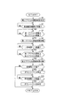
以上のように構成された本発明の実施の形態に係る変速制御装置による変速制御動作について図2を参照して説明する。以下に説明する変速制御動作は、EG−ECU5においてクルーズコントロール機能がオンとなったときに実行される。 The shift control operation by the shift control apparatus according to the embodiment of the present invention configured as described above will be described with reference to FIG. The shift control operation described below is executed when the cruise control function is turned on in the EG-ECU 5.
まず、TM−ECU6は、車速と第2アクセル開度とに基づいて変速機4のギヤ比を制御する第2アクセル開度参照状態をとる(ステップS1)。次いで、TM−ECU6は、EG−ECU5において車速維持機能が作動するのを待つ(ステップS2)。 First, the TM-ECU 6 takes a second accelerator opening reference state in which the gear ratio of the transmission 4 is controlled based on the vehicle speed and the second accelerator opening (step S1). Next, the TM-ECU 6 waits for the vehicle speed maintenance function to operate in the EG-ECU 5 (step S2).
EG−ECU5において車速維持機能が作動した場合には、TM−ECU6は、第1アクセル開度が第2アクセル開度以下となるのを待つ(ステップS3)。第1アクセル開度が第2アクセル開度以下となった場合には、TM−ECU6は、車速と第1アクセル開度とに基づいて変速機4のギヤ比を制御する第1アクセル開度参照状態をとる(ステップS4)。 When the vehicle speed maintaining function is activated in the EG-ECU 5, the TM-ECU 6 waits for the first accelerator opening to become equal to or less than the second accelerator opening (step S3). When the first accelerator opening is equal to or less than the second accelerator opening, the TM-ECU 6 refers to the first accelerator opening that controls the gear ratio of the transmission 4 based on the vehicle speed and the first accelerator opening. A state is taken (step S4).
次いで、TM−ECU6は、一定時間T1が経過するのを待つ(ステップS5)。一定時間T1が経過した場合には、TM−ECU6は、第1アクセル開度が第2アクセル開度以上となるのを待つ(ステップS6)。 Next, the TM-ECU 6 waits for a certain time T1 to elapse (step S5). When the predetermined time T1 has elapsed, the TM-ECU 6 waits for the first accelerator opening to become greater than or equal to the second accelerator opening (step S6).
第1アクセル開度が第2アクセル開度以上となった場合には、TM−ECU6は、車速と第2アクセル開度とに基づいて変速機4のギヤ比を制御する第2アクセル開度参照状態をとる(ステップS7)。 When the first accelerator opening is equal to or greater than the second accelerator opening, the TM-ECU 6 refers to the second accelerator opening that controls the gear ratio of the transmission 4 based on the vehicle speed and the second accelerator opening. A state is taken (step S7).
次いで、TM−ECU6は、変速機4のギヤ比が所定のギヤ比より低いか否かを判断する。すなわち、本実施の形態において、変速機4に形成させた変速段が2速より高いか否かを判断する(ステップS8)。 Next, the TM-ECU 6 determines whether or not the gear ratio of the transmission 4 is lower than a predetermined gear ratio. That is, in the present embodiment, it is determined whether or not the shift speed formed in the transmission 4 is higher than the second speed (step S8).
ここで、変速機4に形成させた変速段が2速より高くないと判断した場合には、TM−ECU6は、変速制御動作を終了する。一方、変速機4に形成させた変速段が2速より高いと判断した場合には、TM−ECU6は、変速機4のギヤ比を高く変更することを禁止する。すなわち、TM−ECU6は、変速機4のダウンシフトを禁止する(ステップS9)。 Here, if it is determined that the shift speed formed in the transmission 4 is not higher than the second speed, the TM-ECU 6 ends the shift control operation. On the other hand, if it is determined that the gear stage formed in the transmission 4 is higher than the second speed, the TM-ECU 6 prohibits changing the gear ratio of the transmission 4 to be high. That is, the TM-ECU 6 prohibits the downshift of the transmission 4 (step S9).
次いで、TM−ECU6は、所定時間T2が経過するのを待ち(ステップS10)、所定時間T2が経過した場合には、TM−ECU6は、変速機4のギヤ比を高く変更することを許可する。すなわち、TM−ECU6は、変速機4のダウンシフトを許可する(ステップS11)。その後、TM−ECU6は、変速制御動作を終了する。 Next, the TM-ECU 6 waits for the predetermined time T2 to elapse (step S10), and when the predetermined time T2 elapses, the TM-ECU 6 permits the gear ratio of the transmission 4 to be changed to be high. . That is, the TM-ECU 6 permits a downshift of the transmission 4 (step S11). Thereafter, the TM-ECU 6 ends the shift control operation.
なお、ステップS9で変速機4のダウンシフトを禁止してからステップS11でダウンシフトを許可するまでの間、オートクルーズスイッチ10が操作された場合には、TM−ECU6は、変速機4のダウンシフトを許可して、変速制御動作を終了する。 If the auto-cruise switch 10 is operated between the time when the downshift of the transmission 4 is prohibited at step S9 and the time when the downshift is permitted at step S11, the TM-ECU 6 causes the transmission 4 to be down. The shift is permitted and the shift control operation is terminated.
また、ステップS6において、第1アクセル開度が第2アクセル開度以上となるのを待っている時間が所定時間T3以上となった場合には、TM−ECU6は、フェールセーフとして、第2アクセル開度参照状態をとり、変速制御動作を終了するようにしてもよい。ここで、所定時間T3は、適合値である。 In step S6, if the time waiting for the first accelerator opening to be equal to or greater than the second accelerator opening is equal to or greater than the predetermined time T3, the TM-ECU 6 sets the second accelerator as fail-safe. The opening degree reference state may be taken to end the shift control operation. Here, the predetermined time T3 is a conforming value.
以上のように説明した変速制御動作の作用について、図3及び図4を参照して説明する。なお、図3及び図4において、縦軸は、第1アクセル開度及び第2アクセル開度を示し、横軸は、時刻を示している。また、以下の説明において、クルーズコントロール機能は、オンになっており、TM−ECU6は、第2アクセル開度参照状態にあるものとする。 The operation of the shift control operation described above will be described with reference to FIGS. 3 and 4, the vertical axis indicates the first accelerator opening and the second accelerator opening, and the horizontal axis indicates time. In the following description, it is assumed that the cruise control function is on and the TM-ECU 6 is in the second accelerator opening reference state.
図3において、第1アクセル開度が上昇している状態にある時刻t1で、車速維持機能が作動されると、第1アクセル開度が第2アクセル開度以下となる時刻t2まで、TM−ECU6は、第2アクセル開度参照状態を維持し、時刻t2で、第1アクセル開度参照状態をとる。 In FIG. 3, when the vehicle speed maintenance function is activated at time t1 when the first accelerator opening is increasing, TM− until time t2 when the first accelerator opening is equal to or less than the second accelerator opening. The ECU 6 maintains the second accelerator opening reference state, and takes the first accelerator opening reference state at time t2.
ここで、車速維持機能が作動した時刻t1で、TM−ECU6が第1アクセル開度参照状態をとると、第1アクセル開度が上昇しているため、ダウンシフトが実行されてしまう。このため、TM−ECU6は、第1アクセル開度が第2アクセル開度以下となるまで第2アクセル開度参照状態を維持するようになっている。 Here, if the TM-ECU 6 takes the first accelerator opening reference state at the time t1 when the vehicle speed maintaining function is activated, the first accelerator opening is increased, and thus a downshift is executed. Therefore, the TM-ECU 6 is configured to maintain the second accelerator opening reference state until the first accelerator opening is equal to or less than the second accelerator opening.
その後、時刻t2から一定時間T1が経過した時刻t3を経て、第1アクセル開度が第2アクセル開度未満となっている時刻t4までの間、TM−ECU6は、第1アクセル開度参照状態を維持する。第1アクセル開度が第2アクセル開度以上となった時刻t4で、TM−ECU6は、第2アクセル開度参照状態をとる。 Thereafter, the TM-ECU 6 is in the first accelerator opening reference state until the time t4 when the first accelerator opening is less than the second accelerator opening through the time t3 when the predetermined time T1 has elapsed from the time t2. To maintain. At time t4 when the first accelerator opening becomes equal to or greater than the second accelerator opening, the TM-ECU 6 takes the second accelerator opening reference state.
図4において、第1アクセル開度が一定な状態にある時刻t11で、車速維持機能が作動されると、第1アクセル開度が第2アクセル開度以下であるため、TM−ECU6は、第1アクセル開度参照状態をとる。 In FIG. 4, when the vehicle speed maintenance function is activated at time t11 when the first accelerator opening is constant, the first accelerator opening is equal to or less than the second accelerator opening. Take 1 accelerator opening reference state.
その後、時刻t11から一定時間T1が経過した時刻t12を経て、第1アクセル開度が第2アクセル開度未満となっている時刻t13までの間、TM−ECU6は、第1アクセル開度参照状態を維持する。第1アクセル開度が第2アクセル開度以上となった時刻t13で、TM−ECU6は、第2アクセル開度参照状態をとる。 Thereafter, the TM-ECU 6 is in the first accelerator opening reference state until the time t13 when the first accelerator opening is less than the second accelerator opening through the time t12 when the predetermined time T1 has elapsed from the time t11. To maintain. At time t13 when the first accelerator opening becomes equal to or greater than the second accelerator opening, the TM-ECU 6 takes the second accelerator opening reference state.
ここで、車速維持機能が作動し、第1アクセル開度が第2アクセル開度以下となる時刻t11では、第1アクセル開度が第2アクセル開度以上となっている、すなわち、第1アクセル開度が第2アクセル開度と等しい場合がある。 Here, at time t11 when the vehicle speed maintaining function is activated and the first accelerator opening is equal to or less than the second accelerator opening, the first accelerator opening is equal to or greater than the second accelerator opening. The opening may be equal to the second accelerator opening.
この場合、図4に示すように、時刻t11より後に、第1アクセル開度が第2アクセル開度未満となる。したがって、TM−ECU6が第2アクセル開度参照状態となり、アップシフトが遅延してしまう。 In this case, as shown in FIG. 4, the first accelerator opening is less than the second accelerator opening after time t11. Therefore, the TM-ECU 6 enters the second accelerator opening reference state, and the upshift is delayed.
このような状況が起こることを抑制するため、第1アクセル開度が第2アクセル開度以下となってから一定時間T1が経過するまでは、TM−ECU6は、第1アクセル開度参照状態を維持するようになっている。 In order to suppress such a situation, the TM-ECU 6 keeps the first accelerator opening reference state until the predetermined time T1 has elapsed after the first accelerator opening becomes equal to or less than the second accelerator opening. To maintain.
以上のように、本実施の形態は、車速維持機能が作動していることを条件として、車速と、第1アクセル開度を平滑化した第2アクセル開度とに基づいて変速機4のギヤ比を制御することにより、シフトハンチングの発生を抑制するため、車速維持機能が作動している状態でドライバビリティが低下することを抑制することができる。 As described above, in the present embodiment, the gear of the transmission 4 is based on the vehicle speed and the second accelerator opening obtained by smoothing the first accelerator opening, on condition that the vehicle speed maintaining function is operating. By controlling the ratio, the occurrence of shift hunting can be suppressed, so that drivability can be prevented from decreasing while the vehicle speed maintenance function is operating.
また、本実施の形態は、車速維持機能が作動した後の特定期間には、車速と第1アクセル開度に基づいて変速機4のギヤ比を制御することにより、変速機4のギヤ比を変更するタイミングが遅延することを防止することができる。 Further, in the present embodiment, the gear ratio of the transmission 4 is controlled by controlling the gear ratio of the transmission 4 based on the vehicle speed and the first accelerator opening during a specific period after the vehicle speed maintenance function is activated. It is possible to prevent the timing for changing from being delayed.
また、本実施の形態は、車速維持機能が作動した後、第1アクセル開度が第2アクセル開度以下であれば、車速と第1アクセル開度に基づいて変速機4のギヤ比を制御することにより、車速維持機能が作動したときに、変速機4のギヤ比が変更されることを抑制することができる。 In the present embodiment, after the vehicle speed maintaining function is activated, the gear ratio of the transmission 4 is controlled based on the vehicle speed and the first accelerator opening if the first accelerator opening is equal to or less than the second accelerator opening. By doing so, it is possible to prevent the gear ratio of the transmission 4 from being changed when the vehicle speed maintaining function is activated.
また、本実施の形態は、車速維持機能が作動した後、第1アクセル開度が第2アクセル開度以下になっているときから第1アクセル開度が第2アクセル開度以上になるときまでの期間には、車速と第1アクセル開度に基づいて変速機4のギヤ比を制御することにより、変速機4のギヤ比を変更するタイミングが遅延することを防止することができる。 Further, in the present embodiment, after the vehicle speed maintaining function is activated, from when the first accelerator opening is equal to or smaller than the second accelerator opening until when the first accelerator opening is equal to or larger than the second accelerator opening. During this period, by controlling the gear ratio of the transmission 4 based on the vehicle speed and the first accelerator opening, it is possible to prevent the timing for changing the gear ratio of the transmission 4 from being delayed.
また、本実施の形態は、例えば、第1アクセル開度と第2アクセル開度とが等しい状態で車速維持機能が作動した後、一定時間T1が経過するまでは、車速と第1アクセル開度に基づいて変速機4のギヤ比を制御するため、第1アクセル開度が変化したことにより変速機4のギヤ比を変更する必要が生じたときに、変速機4のギヤ比を変更するタイミングが遅延することを防止することができる。 Further, in the present embodiment, for example, after the vehicle speed maintaining function is activated in a state where the first accelerator opening is equal to the second accelerator opening, the vehicle speed and the first accelerator opening are elapsed until a certain time T1 elapses. To change the gear ratio of the transmission 4 when the gear ratio of the transmission 4 needs to be changed due to the change in the first accelerator opening. Can be prevented from being delayed.
また、本実施の形態は、特定期間が経過した後、変速機4のギヤ比を制御するために参照されるアクセル開度が第1アクセル開度から第2アクセル開度に変更されることによって、変速機4のギヤ比が高く変更され、シフトハンチングが発生することを抑制することができる。 Further, in the present embodiment, after a specific period has elapsed, the accelerator opening that is referred to for controlling the gear ratio of the transmission 4 is changed from the first accelerator opening to the second accelerator opening. The gear ratio of the transmission 4 is changed to be high and shift hunting can be prevented from occurring.
なお、本実施の形態において、EG−ECU5は、PID制御などのフィードバック制御によって、車速を目標車速とするためのエンジン2の目標出力を算出するものとして説明した。 In the present embodiment, the EG-ECU 5 has been described as calculating the target output of the engine 2 for setting the vehicle speed to the target vehicle speed by feedback control such as PID control.
これに対し、EG−ECU5は、車速を目標車速とするためのエンジン2の目標出力を他の公知な態様で算出してもよい。例えば、特許文献1に開示されたように、EG−ECU5は、車速を目標車速とするためのエンジン2の目標出力を目標加速度から算出するようにしてもよい。
On the other hand, the EG-ECU 5 may calculate the target output of the engine 2 for setting the vehicle speed to the target vehicle speed in another known manner. For example, as disclosed in
以上、本発明の実施の形態を開示したが、当業者によっては本発明の範囲を逸脱することなく変更が加えられうることは明白である。すべてのこのような修正及び等価物が特許請求の範囲に記載された請求項に含まれることが意図されている。 Although the embodiments of the present invention have been disclosed above, it is obvious that those skilled in the art can make modifications without departing from the scope of the present invention. All such modifications and equivalents are intended to be included in the claims recited in the claims.
1 車両
2 エンジン
4 変速機
20 第1アクセル開度算出部
21 第2アクセル開度算出部
22 変速制御部
DESCRIPTION OF
Claims (4)
車速とエンジンの目標出力とに応じた第1アクセル開度を算出する第1アクセル開度算出部と、
前記第1アクセル開度を平滑化した第2アクセル開度を算出する第2アクセル開度算出部と、
前記車速維持機能が作動していることを条件として、前記車速と前記第2アクセル開度とに基づいて前記変速機のギヤ比を制御する変速制御部と、を備え、
前記変速制御部は、前記車速維持機能が作動した後の特定期間には、前記車速と前記第1アクセル開度とに基づいて前記変速機のギヤ比を制御し、
前記特定期間は、前記第1アクセル開度が前記第2アクセル開度以下になると開始される変速制御装置。 A shift control device for controlling a transmission provided in a vehicle having a vehicle speed maintaining function for controlling to maintain a vehicle speed,
A first accelerator opening calculation unit that calculates a first accelerator opening according to a vehicle speed and a target output of the engine;
A second accelerator opening calculation unit for calculating a second accelerator opening obtained by smoothing the first accelerator opening;
On condition that the vehicle speed maintenance function is activated, e Bei and a transmission control unit for controlling the gear ratio of the transmission based on said said vehicle speed second accelerator opening,
The shift control unit controls a gear ratio of the transmission based on the vehicle speed and the first accelerator opening during a specific period after the vehicle speed maintaining function is activated.
The shift control device that is started when the first accelerator opening is equal to or less than the second accelerator opening during the specific period .
請求項1に記載の変速制御装置。 The specific period ends when the first accelerator opening is equal to or greater than the second accelerator opening.
The shift control apparatus according to claim 1 .
装置。 The shift control device according to claim 1 or 2 , wherein the specific period continues for at least a predetermined time.
り低いことを条件として、所定時間にわたって、前記変速機のギヤ比を高く変更すること
を禁止する請求項1ないし請求項3のいずれか1の請求項に記載の変速制御装置。 The shift control unit prohibits changing the gear ratio of the transmission to be high for a predetermined time after the specific period has elapsed, on condition that the gear ratio of the transmission is lower than a predetermined gear ratio. The shift control apparatus according to any one of claims 1 to 3 .
Priority Applications (3)
| Application Number | Priority Date | Filing Date | Title |
|---|---|---|---|
| JP2014098820A JP6314640B2 (en) | 2014-05-12 | 2014-05-12 | Shift control device |
| PCT/JP2015/063113 WO2015174302A1 (en) | 2014-05-12 | 2015-05-01 | Transmission control device |
| DE112015002222.8T DE112015002222B4 (en) | 2014-05-12 | 2015-05-01 | TRANSMISSION CONTROL DEVICE |
Applications Claiming Priority (1)
| Application Number | Priority Date | Filing Date | Title |
|---|---|---|---|
| JP2014098820A JP6314640B2 (en) | 2014-05-12 | 2014-05-12 | Shift control device |
Publications (2)
| Publication Number | Publication Date |
|---|---|
| JP2015215057A JP2015215057A (en) | 2015-12-03 |
| JP6314640B2 true JP6314640B2 (en) | 2018-04-25 |
Family
ID=54479843
Family Applications (1)
| Application Number | Title | Priority Date | Filing Date |
|---|---|---|---|
| JP2014098820A Active JP6314640B2 (en) | 2014-05-12 | 2014-05-12 | Shift control device |
Country Status (3)
| Country | Link |
|---|---|
| JP (1) | JP6314640B2 (en) |
| DE (1) | DE112015002222B4 (en) |
| WO (1) | WO2015174302A1 (en) |
Family Cites Families (11)
| Publication number | Priority date | Publication date | Assignee | Title |
|---|---|---|---|---|
| JPH0241941A (en) * | 1988-07-30 | 1990-02-13 | Aisin Aw Co Ltd | Hunting prevention method on constant speed running condition by cruise control for vehicle and electronic controller therefor |
| JPH0277334A (en) * | 1988-09-14 | 1990-03-16 | Diesel Kiki Co Ltd | Constant speed running control method for vehicle |
| JP2000318486A (en) * | 1999-05-14 | 2000-11-21 | Honda Motor Co Ltd | Speed control device for vehicle |
| DE10115052A1 (en) | 2000-04-17 | 2001-10-25 | Bosch Gmbh Robert | Setting transmission ratio in motor vehicle with distance and/or speed regulator involves setting ratio depending on restricted demand value in normal mode or restricted demand value |
| DE102004012908A1 (en) | 2004-03-17 | 2005-10-06 | Daimlerchrysler Ag | Device and method for moderating speed of reaction of electronic control devices related to vehicle with automated speed control |
| US7555368B2 (en) | 2006-07-24 | 2009-06-30 | Gm Global Technology Operations, Inc. | Synthesized control input |
| DE102006034380B4 (en) | 2006-07-25 | 2017-06-29 | Robert Bosch Gmbh | Method for determining the pedal travel in cruise control |
| JP4994794B2 (en) * | 2006-11-13 | 2012-08-08 | 富士重工業株式会社 | Vehicle cruise control device |
| JP2010284989A (en) * | 2009-06-09 | 2010-12-24 | Daihatsu Motor Co Ltd | Drive control apparatus of vehicle |
| JP5285635B2 (en) * | 2010-02-03 | 2013-09-11 | 富士重工業株式会社 | Control device for continuously variable transmission |
| JP5833889B2 (en) * | 2011-11-08 | 2015-12-16 | 富士重工業株式会社 | Vehicle travel control device |
-
2014
- 2014-05-12 JP JP2014098820A patent/JP6314640B2/en active Active
-
2015
- 2015-05-01 WO PCT/JP2015/063113 patent/WO2015174302A1/en active Application Filing
- 2015-05-01 DE DE112015002222.8T patent/DE112015002222B4/en active Active
Also Published As
| Publication number | Publication date |
|---|---|
| WO2015174302A1 (en) | 2015-11-19 |
| DE112015002222B4 (en) | 2022-10-06 |
| DE112015002222T5 (en) | 2017-02-09 |
| JP2015215057A (en) | 2015-12-03 |
Similar Documents
| Publication | Publication Date | Title |
|---|---|---|
| JP4400617B2 (en) | Powertrain control device, control method, program for realizing the method, and recording medium recording the program | |
| CN108443488B (en) | Vehicle control device | |
| JP6006884B2 (en) | Hydraulic switch failure judgment device | |
| JP6142854B2 (en) | Vehicle control apparatus and vehicle control method | |
| JPWO2017203874A1 (en) | Control device and control method for vehicle with continuously variable transmission | |
| JP2008045565A (en) | Vehicle control device | |
| WO2017033900A1 (en) | Control device for automatic transmission | |
| JP6314640B2 (en) | Shift control device | |
| JP6567782B2 (en) | Speed change control device and speed change control method for continuously variable transmission | |
| KR100901677B1 (en) | Control apparatus for vehicle and method of controlling vehicle | |
| KR101686798B1 (en) | Automatic transmission apparatus and damper clutch control method thereof | |
| JP2010249190A (en) | Control device of automatic transmission for vehicle | |
| JP6375527B2 (en) | Control device for variable displacement oil pump | |
| JP6273876B2 (en) | Shift control device | |
| JP6307375B2 (en) | Hydraulic control device and control method thereof | |
| JP5566156B2 (en) | Automatic transmission lockup control method | |
| KR102062430B1 (en) | Starting control device and method of vehicle according to recognition of out-of-synchronization | |
| JP2013217271A (en) | Vehicle control device | |
| JP5026402B2 (en) | Automatic transmission for vehicle | |
| JP4281766B2 (en) | Vehicle control device | |
| JP6323255B2 (en) | Vehicle control device | |
| JP2017032074A (en) | Controller of belt type continuously variable transmission | |
| JP2016104995A (en) | Abrupt start prevention control device of vehicle | |
| JP6643103B2 (en) | Automatic transmission lock-up control device and automatic transmission lock-up control method | |
| JP2016044804A (en) | transmission |
Legal Events
| Date | Code | Title | Description |
|---|---|---|---|
| A621 | Written request for application examination |
Free format text: JAPANESE INTERMEDIATE CODE: A621 Effective date: 20170131 |
|
| A131 | Notification of reasons for refusal |
Free format text: JAPANESE INTERMEDIATE CODE: A131 Effective date: 20170912 |
|
| A521 | Request for written amendment filed |
Free format text: JAPANESE INTERMEDIATE CODE: A523 Effective date: 20170925 |
|
| TRDD | Decision of grant or rejection written | ||
| A01 | Written decision to grant a patent or to grant a registration (utility model) |
Free format text: JAPANESE INTERMEDIATE CODE: A01 Effective date: 20180227 |
|
| A61 | First payment of annual fees (during grant procedure) |
Free format text: JAPANESE INTERMEDIATE CODE: A61 Effective date: 20180312 |
|
| R151 | Written notification of patent or utility model registration |
Ref document number: 6314640 Country of ref document: JP Free format text: JAPANESE INTERMEDIATE CODE: R151 |