JP6308852B2 - Driving apparatus, lithographic apparatus, and article manufacturing method - Google Patents
Driving apparatus, lithographic apparatus, and article manufacturing method Download PDFInfo
- Publication number
- JP6308852B2 JP6308852B2 JP2014083454A JP2014083454A JP6308852B2 JP 6308852 B2 JP6308852 B2 JP 6308852B2 JP 2014083454 A JP2014083454 A JP 2014083454A JP 2014083454 A JP2014083454 A JP 2014083454A JP 6308852 B2 JP6308852 B2 JP 6308852B2
- Authority
- JP
- Japan
- Prior art keywords
- actuator
- thrust
- control unit
- actuators
- unit
- Prior art date
- Legal status (The legal status is an assumption and is not a legal conclusion. Google has not performed a legal analysis and makes no representation as to the accuracy of the status listed.)
- Active
Links
Images


Classifications
-
- B—PERFORMING OPERATIONS; TRANSPORTING
- B29—WORKING OF PLASTICS; WORKING OF SUBSTANCES IN A PLASTIC STATE IN GENERAL
- B29C—SHAPING OR JOINING OF PLASTICS; SHAPING OF MATERIAL IN A PLASTIC STATE, NOT OTHERWISE PROVIDED FOR; AFTER-TREATMENT OF THE SHAPED PRODUCTS, e.g. REPAIRING
- B29C43/00—Compression moulding, i.e. applying external pressure to flow the moulding material; Apparatus therefor
- B29C43/32—Component parts, details or accessories; Auxiliary operations
- B29C43/58—Measuring, controlling or regulating
-
- G—PHYSICS
- G03—PHOTOGRAPHY; CINEMATOGRAPHY; ANALOGOUS TECHNIQUES USING WAVES OTHER THAN OPTICAL WAVES; ELECTROGRAPHY; HOLOGRAPHY
- G03F—PHOTOMECHANICAL PRODUCTION OF TEXTURED OR PATTERNED SURFACES, e.g. FOR PRINTING, FOR PROCESSING OF SEMICONDUCTOR DEVICES; MATERIALS THEREFOR; ORIGINALS THEREFOR; APPARATUS SPECIALLY ADAPTED THEREFOR
- G03F7/00—Photomechanical, e.g. photolithographic, production of textured or patterned surfaces, e.g. printing surfaces; Materials therefor, e.g. comprising photoresists; Apparatus specially adapted therefor
- G03F7/70—Microphotolithographic exposure; Apparatus therefor
- G03F7/70691—Handling of masks or workpieces
- G03F7/70716—Stages
- G03F7/70725—Stages control
-
- G—PHYSICS
- G05—CONTROLLING; REGULATING
- G05B—CONTROL OR REGULATING SYSTEMS IN GENERAL; FUNCTIONAL ELEMENTS OF SUCH SYSTEMS; MONITORING OR TESTING ARRANGEMENTS FOR SUCH SYSTEMS OR ELEMENTS
- G05B19/00—Programme-control systems
- G05B19/02—Programme-control systems electric
- G05B19/18—Numerical control [NC], i.e. automatically operating machines, in particular machine tools, e.g. in a manufacturing environment, so as to execute positioning, movement or co-ordinated operations by means of programme data in numerical form
- G05B19/404—Numerical control [NC], i.e. automatically operating machines, in particular machine tools, e.g. in a manufacturing environment, so as to execute positioning, movement or co-ordinated operations by means of programme data in numerical form characterised by control arrangements for compensation, e.g. for backlash, overshoot, tool offset, tool wear, temperature, machine construction errors, load, inertia
-
- H—ELECTRICITY
- H01—ELECTRIC ELEMENTS
- H01J—ELECTRIC DISCHARGE TUBES OR DISCHARGE LAMPS
- H01J37/00—Discharge tubes with provision for introducing objects or material to be exposed to the discharge, e.g. for the purpose of examination or processing thereof
- H01J37/02—Details
- H01J37/20—Means for supporting or positioning the objects or the material; Means for adjusting diaphragms or lenses associated with the support
-
- H—ELECTRICITY
- H01—ELECTRIC ELEMENTS
- H01J—ELECTRIC DISCHARGE TUBES OR DISCHARGE LAMPS
- H01J37/00—Discharge tubes with provision for introducing objects or material to be exposed to the discharge, e.g. for the purpose of examination or processing thereof
- H01J37/30—Electron-beam or ion-beam tubes for localised treatment of objects
- H01J37/317—Electron-beam or ion-beam tubes for localised treatment of objects for changing properties of the objects or for applying thin layers thereon, e.g. for ion implantation
- H01J37/3174—Particle-beam lithography, e.g. electron beam lithography
-
- B—PERFORMING OPERATIONS; TRANSPORTING
- B29—WORKING OF PLASTICS; WORKING OF SUBSTANCES IN A PLASTIC STATE IN GENERAL
- B29C—SHAPING OR JOINING OF PLASTICS; SHAPING OF MATERIAL IN A PLASTIC STATE, NOT OTHERWISE PROVIDED FOR; AFTER-TREATMENT OF THE SHAPED PRODUCTS, e.g. REPAIRING
- B29C43/00—Compression moulding, i.e. applying external pressure to flow the moulding material; Apparatus therefor
- B29C43/32—Component parts, details or accessories; Auxiliary operations
- B29C43/58—Measuring, controlling or regulating
- B29C2043/5833—Measuring, controlling or regulating movement of moulds or mould parts, e.g. opening or closing, actuating
-
- G—PHYSICS
- G05—CONTROLLING; REGULATING
- G05B—CONTROL OR REGULATING SYSTEMS IN GENERAL; FUNCTIONAL ELEMENTS OF SUCH SYSTEMS; MONITORING OR TESTING ARRANGEMENTS FOR SUCH SYSTEMS OR ELEMENTS
- G05B2219/00—Program-control systems
- G05B2219/30—Nc systems
- G05B2219/45—Nc applications
- G05B2219/45028—Lithography
-
- G—PHYSICS
- G05—CONTROLLING; REGULATING
- G05B—CONTROL OR REGULATING SYSTEMS IN GENERAL; FUNCTIONAL ELEMENTS OF SUCH SYSTEMS; MONITORING OR TESTING ARRANGEMENTS FOR SUCH SYSTEMS OR ELEMENTS
- G05B2219/00—Program-control systems
- G05B2219/30—Nc systems
- G05B2219/50—Machine tool, machine tool null till machine tool work handling
- G05B2219/50218—Synchronize groups of axis, spindles
-
- H—ELECTRICITY
- H01—ELECTRIC ELEMENTS
- H01J—ELECTRIC DISCHARGE TUBES OR DISCHARGE LAMPS
- H01J2237/00—Discharge tubes exposing object to beam, e.g. for analysis treatment, etching, imaging
- H01J2237/20—Positioning, supporting, modifying or maintaining the physical state of objects being observed or treated
- H01J2237/202—Movement
- H01J2237/20221—Translation
- H01J2237/20228—Mechanical X-Y scanning
-
- H—ELECTRICITY
- H01—ELECTRIC ELEMENTS
- H01J—ELECTRIC DISCHARGE TUBES OR DISCHARGE LAMPS
- H01J2237/00—Discharge tubes exposing object to beam, e.g. for analysis treatment, etching, imaging
- H01J2237/20—Positioning, supporting, modifying or maintaining the physical state of objects being observed or treated
- H01J2237/202—Movement
- H01J2237/20278—Motorised movement
- H01J2237/20285—Motorised movement computer-controlled
Description
本発明は、駆動装置、リソグラフィ装置、および物品の製造方法に関する。 The present invention relates to a drive device, a lithographic apparatus, and an article manufacturing method.
ロボットや運輸機械、および産業機械等において、その位置を制御した状態で駆動する可動部を有しているものが知られている。これら駆動装置の位置決め機構が故障すると、故障箇所の特定および部品の修理・交換等の復旧作業のため、駆動装置を長時間停止しなければならず、スループットが低下する。また、復旧作業に伴う駆動装置の停止時間を短縮するため、駆動装置内の各ユニットに自己監視や診断を行うためのセンサ等の機構を設けることにより性能を維持および管理する方法もあるが、自己診断のためのみの部品は装置にとって冗長でありコストアップを招く。そこで、特許文献1は、駆動機構における動特性の経時的な変化を同定し、性能維持の適否を自己判断する装置を開示している。特許文献2は、複数のアクチュエータを有する一つの可動部において、各アクチュエータの推力バランスを監視し、異常判定する装置を開示している。
2. Description of the Related Art Robots, transport machines, industrial machines, and the like are known that have a movable part that is driven in a state in which the position is controlled. When the positioning mechanism of these drive devices breaks down, the drive device must be stopped for a long period of time for recovery operations such as identification of a failure location and repair / replacement of parts, resulting in a decrease in throughput. There is also a method for maintaining and managing the performance by providing a mechanism such as a sensor for performing self-monitoring and diagnosis in each unit in the drive unit in order to shorten the stop time of the drive unit accompanying the restoration work. Parts used only for self-diagnosis are redundant for the apparatus, resulting in increased costs. Therefore,
しかしながら、特許文献1の装置は、装置全体の入出力特性の変化にのみ着目する装置であり、装置内部の故障原因を特定することはできない。さらに、動特性を同定する際、同定精度を向上させるために高次のモデル化が必要となるが、高次成分は、機差やノイズ等の影響を受けるため、高精度にデータを取得することができない。また、特許文献2の装置は、駆動機構が異常か否かを検出するのみで、故障箇所の特定および状態の定量的捕捉ができない。
However, the device of
本発明は、例えば、自己診断に有利な駆動装置を提供することを目的とする。 An object of the present invention is to provide a driving device that is advantageous for self-diagnosis, for example.
上記課題を解決するために、本発明は、可動部と、可動部の位置を計測する計測部と、可動部に関して実質的に共通の作用軸を有する2つの推力をそれぞれ生成する2つのアクチュエータと、計測部により計測された位置に基づいて2つのアクチュエータにより位置を制御する制御部とを含む駆動装置であって、制御部は、2つのアクチュエータのうちの一方のアクチュエータに推力を生成させた状態で2つのアクチュエータのうちの他方のアクチュエータにより位置を制御した場合に2つのアクチュエータに係る推力指令と計測部により計測された位置とに基づいて推定された外乱力と、一方のアクチュエータに係る推力指令との関係に基づいて、一方のアクチュエータの推力定数、他方のアクチュエータの推力定数、および作用軸に関して可動部を支持する部材の剛性のうちの少なくとも1つに関する情報を得ることを特徴とする。 In order to solve the above-described problems, the present invention provides a movable part, a measurement part that measures the position of the movable part , and two actuators that respectively generate two thrusts having a substantially common action axis with respect to the movable part. , A drive device including a control unit that controls the position by two actuators based on the position measured by the measurement unit , wherein the control unit generates thrust in one of the two actuators And when the position is controlled by the other of the two actuators, the disturbance force estimated based on the thrust command related to the two actuators and the position measured by the measuring unit, and the thrust command related to the one actuator The thrust constant of one actuator, the thrust constant of the other actuator, and the axis of action And wherein the obtaining information on at least one of the rigid members for supporting the movable portion.
本発明によれば、例えば、自己診断に有利な駆動装置を提供することができる。 According to the present invention, for example, it is possible to provide a driving device advantageous for self-diagnosis.
以下、本発明を実施するための形態について図面などを参照して説明する。 Hereinafter, embodiments for carrying out the present invention will be described with reference to the drawings.
まず、本発明に係る駆動装置の構成について説明する。図1は、本発明の一実施形態に係る駆動装置100の構成を示す概略図である。この駆動装置100は、ロボットや運輸機械、および産業機械等の様々な機械内で、複数のアクチュエータにより可動部を駆動させる装置である。駆動装置100は可動部103、2つのアクチュエータ101、102、弾性体104、および位置センサ106を同一の自由度内に備える。
First, the structure of the drive device according to the present invention will be described. FIG. 1 is a schematic diagram showing a configuration of a
可動部103は、その位置を制御された状態で、支持構造体105に支持され可動する部材である。2つのアクチュエータ101、102は、作用軸を共有した状態で、可動部103と支持構造体105との間に設置され、それぞれ印加される電流に応じて可動部103を駆動させる推力を発生される駆動機構である。このように1つの可動部103に対し、2つのアクチュエータ101、102を分散配置することにより、アクチュエータの発熱による周囲の熱ダメージが軽減され、応力の分散による可動部103および支持構造体105の変形が抑制される。なお、本発明においては、1つの可動部に対し、2つのアクチュエータを設置する構成とするが、この構成に限定されず、可動部103の可動方向と同一方向の作用軸を有していれば、アクチュエータは、3つ以上設置してもよい。弾性体104は、例えば、コイルバネを使用し、可動部103と支持構造体105の間に設置され、可動部103の振動等を抑制し支持する。なお、図1において、弾性体104は、可動部103の可動方向と同自由度方向の弾性成分の合計とする。本発明においては、1つの可動部103に対し、1つの弾性体104を備える構成とするが、この構成に限定されず、複数の弾性体104を備える構成であってもよい。位置センサ106は、可動部103と支持構造体105との相対位置を計測する計測部である。位置センサ106で計測された相対位置を位置情報として制御部107に送信し、制御部107は、該位置情報に基づき、アクチュエータ101、102を駆動させ、可動部103の位置を制御する。
The
制御部107は、例えば、電気回路またはソフトウェアなどで構成され、駆動装置100の各ユニットの動作および調整などを制御し得る。この制御部107は、外乱オブザーバ108と、不図示の記憶装置とを有し、駆動装置100の各ユニットに回線を介して接続され、プログラムなどに従って、各ユニットの制御を実行し得る。本発明の制御部107は、少なくとも、外乱オブザーバ108を用いて、推定外乱算出処理および故障診断処理を含む位置制御を実行するものとする。外乱オブザーバ108は、制御部107の位置制御系に組み込まれ、制御性能の向上を図る機構であり、各ユニットのパラメータと入出力特性とから、可動部103が受けるであろうと推定される外乱力(推定外乱do)を算出する。制御部107は、外乱オブザーバ108により算出された推定外乱doを、記憶装置に保存されている所定の閾値(基準値)と比較する。なお、制御部107は、駆動装置100の他の部分と一体で(共通の筐体内に)構成してもよいし、駆動装置100の他の部分とは別体で(別の筐体内に)構成してもよい。
The
次に、本実施形態に係る駆動装置の推定外乱算出処理について説明する。なお、本明細書において、推定外乱算出処理とは、可動部103の位置制御において、可動部103に生じた外乱力を推定し、その推定外乱doを常時監視することにより、装置のパラメータの変化を監視する処理である。図2は、推定外乱算出処理の機能ブロック図である。まず、制御部107は、可動部103の目標位置xrefと位置センサ106によって得られる可動部103の位置信号xとの差分と、補償器Cの演算により、アクチュエータ101、102への推力指令値irefを算出する。推力指令値irefは、アクチュエータ101、102に出力させる推力を指示する推力指令の値であり、ドライブ回路KDを経て、各アクチュエータ101、102に印加する電流i1、i2に変換される。アクチュエータ101、102は、それぞれ、電流i1、i2を、アクチュエータ101、102が有する推力定数D1、D2により、アクチュエータの推力f1、f2へと変換する。このように、可動部103は、アクチュエータ101、102で発生する推力f1、f2の合力により駆動する。ここで、可動部103には、アクチュエータによる制御力以外に、例えば、支持構造体105の振動が、電気ケーブルや弾性体104を介して可動部103へ伝達する力などによる外乱力dも印加される。可動部103にアクチュエータ101、102の推力以外に外乱力dが印加されると、可動部103の位置制御精度が低下し得る。
Next, the estimated disturbance calculation process of the drive device according to the present embodiment will be described. In the present specification, the estimated disturbance calculation process, in the position control of the
そこで、可動部の位置制御においては、外乱オブザーバを位置制御系に組み込むことで、制御性能の向上を図る手法が従来から知られている。図2に示す外乱オブザーバ108のブロックは、可動部103に印加される外乱力を推定する演算部分を示す。この推定外乱doは、以下の式(1)で算出することができる。
Therefore, in the position control of the movable part, a technique for improving the control performance by incorporating a disturbance observer in the position control system has been conventionally known. The block of the
![]()
![]()
式中、右辺第1項および第2項は、制御対象を数式化したものであり、右辺第3項および第4項は、制御力を表す。 In the formula, the first term and the second term on the right side are obtained by formulating the controlled object, and the third term and the fourth term on the right side represent the control force.
なお、実際の装置において推定外乱doに含まれる成分は、主に3種類に分別することができる。第1の成分は、前述した可動部103にかかる外乱力dである。第2の成分は、式(1)の中で使用しているパラメータと実際のパラメータとの差異である。装置内のユニットのパラメータ変化分も推定外乱doの一部である。第3の成分は、式(1)に含まれないアンモデル成分である。実際の装置では、外乱力dは、式(1)で数式化した成分以外にも、センサ応答、ドライバ応答の電気的動特性、構造体の高次モード、粘性および摩擦などの非線形成分などにより、複雑に構成される。このような式(1)に含まれないアンモデル成分も推定外乱doの一部として算出される。
Incidentally, components contained in the estimated disturbance d o In the actual devices can be divided into three main types. The first component is the disturbance force d applied to the
そこで、推定外乱doの静特性のみに着目すると、式(1)は、式(2)に変換することができる。 Therefore, when attention is focused only on the static characteristics of the estimated disturbance d o, equation (1) can be converted into equation (2).
![]()
![]()
静特性のみに着目することにより、動特性の項を削除することができるとともに、実際には、推定外乱doに含まれる第3の成分が小さくなり、第3の成分を考慮せずとも、推定外乱doの算出精度を向上させることができる。式(2)において、第1の成分である外乱力dが小さい場合、もしくは、外乱力dが既知である場合について考えると、推定外乱doは、第2の成分である装置内のユニットのパラメータ変化を主成分として算出されることがわかる。上述のように、推定外乱doの変化から、装置内のユニットのパラメータ変化量を抽出することが可能である。 By paying attention only to the static characteristics, it is possible to remove the section dynamics, in practice, the third component contained in the estimated disturbance d o is reduced, even without considering the third component, it is possible to improve the calculation accuracy of the estimated disturbance d o. In the formula (2), when the disturbance force d is the first component is small, or, considering the case disturbance force d is known, the estimated disturbance d o is the unit in the apparatus according to a second component It can be seen that the parameter change is calculated as the main component. As described above, the change in the estimated disturbance d o, it is possible to extract the parameter change amount of the units in the device.
駆動装置100において、可動部103は、アクチュエータ101、102により、その位置xを制御した状態で駆動するとともに、外乱オブザーバ108を用いて推定外乱doが常時監視されている。推定外乱doの変化量が、所定の閾値を越えた場合には、なんらかの異常があったものと判断する。但し、この時点ではいずれかのパラメータに変化が生じたことを検知するのみで、装置内のどのユニットのパラメータが変化しているかについて特定することができない。そこで、推定外乱doの変化量が、所定の閾値を越えた場合には、故障診断処理に移行する。故障診断処理の詳細については、後述する。
In the
ここで、このような故障診断処理について説明する。なお、本明細書において、故障診断処理とは、装置内のユニットのうち、推定外乱doの変化に影響を与えたユニットを特定する処理である。図3は、故障診断処理の制御ブロック図である。なお、図3において、図2と同様の構成については、同一の番号を付し、説明を省略する。上述のように、推定外乱算出処理において、推定外乱doの値が所定の閾値を超えた場合、制御部107は、駆動装置100の位置制御を故障診断処理へと移行させる。図3に示すように、故障診断処理では、2つのアクチュエータ101、102による位置制御システムを停止させ、アクチュエータ101のみを用いて可動部103の位置を制御する。アクチュエータ101により可動部103の位置が制御されている状態で、アクチュエータ102に故障を診断するための診断信号205を入力する。この診断信号205は、ドライブ回路KDにより、診断電流ipに変換される。
Here, such a failure diagnosis process will be described. In this specification, the fault diagnosis processing, among the units in the apparatus, a process for specifying a unit affected changes in the estimated disturbance d o. FIG. 3 is a control block diagram of failure diagnosis processing. In FIG. 3, the same components as those in FIG. 2 are denoted by the same reference numerals and description thereof is omitted. As described above, in the estimated disturbance calculation process, when the value of the estimated disturbance d o exceeds a predetermined threshold value, the
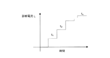
ここで、故障診断処理で用いる診断信号205とは、静的な信号を含み、少なくとも2点以上の異なる動作点を有する信号である。本発明では一例として、図4に示すような時間とともに階段状に変化する診断電流ipを生成する信号を診断信号205として使用するが、これに限定せず、静的な信号を含み、少なくとも2点以上の異なる動作点を有する信号であればよい。
Here, the
図3に示す故障診断処理において、静特性にのみ着目した際の推定外乱doは、式(3)を用いて算出することができる。 In the failure diagnosis processing shown in FIG. 3, the estimated disturbance d o at the time of focusing only on the static characteristics can be calculated using equation (3).
![]()
D1:アクチュエータ101の推力定数[N/A]
D2:アクチュエータ102の推力定数[N/A]
do:推定外乱[N]
i1:アクチュエータ101に流れる電流[A]
ip:アクチュエータ102に流れる診断電流[A]
![]()
D 1 : Thrust constant of actuator 101 [N / A]
D 2 : Thrust constant of actuator 102 [N / A]
d o: estimated disturbance [N]
i 1 : current flowing in the actuator 101 [A]
i p : Diagnostic current flowing in the actuator 102 [A]
ここで、式(3)の右辺第1項は、システムが受ける力を表し、右辺第2項および第3項は、アクチュエータ101、102が可動部103に与えている推力を表す。これら第1項と、第2項および第3項との差分を算出することにより、外乱力を推定することが可能となる。
Here, the first term on the right side of Equation (3) represents the force received by the system, and the second and third terms on the right side represent the thrust applied to the
さらに、式(3)において、外乱力d、パラメータ変化量および診断電流ipがすべてゼロ、かつアクチュエータ101によって可動部103の位置が変化しないと仮定すると、式(3)の右辺第1項と右辺第2項とが一致するため、推定外乱doは、ゼロとなる。
Furthermore, in the equation (3), assuming that the disturbance force d, the position of the
続いて、一定の診断電流ipを与えた場合の推定外乱doは、式(4)で表すことができる。 Then, the estimated disturbance d o when given a constant diagnosis current i p can be expressed by Equation (4).
![]()
![]()
ここで、式(4)の右辺第4項は、診断電流ipによりアクチュエータ102から発生した推力を表し、第2項は、アクチュエータ101により発生する可動部103の位置を制御する電流を表す。第3項は、アクチュエータ102の推力を相殺するための電流を表す。なお、式中、i1_constとは、診断電流ipがゼロのときのアクチュエータ101に印加される電流値である。ここで、アクチュエータ101により可動部103の位置が一定に保たれているとすると、可動部の位置xは、変化しない。よって、式(4)の右辺第1項および第2項は、一定値であることがわかる。
Here, fourth term on the right-hand side of Equation (4) represents the thrust force generated from the actuator 102 by the diagnosis current i p, the second term represents the current for controlling the position of the
このように、式(4)は、診断電流ipに依存して変化する成分と、診断電流ipに関わらず一定である成分とに分けることができ、式(4)は、式(5)のような1次式に置き換えることができる。 Thus, equation (4) can be divided a component that changes depending on the diagnostic current i p, in the component which is constant regardless of the diagnosis current i p, Equation (4) has the formula (5 ).
![]()
![]()
診断電流ipに依存する成分は、1次の係数として推力定数D1およびD2をパラメータとする傾きFとなり、一定値となる成分は、0次の係数として支持剛性(剛性)Kおよび推力定数D1をパラメータとする切片Cとなる。本発明は、式(5)に基づき、支持剛性K、推力定数D1、D2のパラメータ変化を個別に検出し、駆動装置100内のユニットのパラメータ変化に関する情報を取得するものである。
Component dependent on the diagnostic current i p is the slope F becomes to parameter thrust constant D 1 and D 2 as a primary factor, component as a constant value, the support rigidity (stiffness) K and thrust as 0-order coefficient The intercept C has the constant D 1 as a parameter. In the present invention, based on the equation (5), parameter changes of the support stiffness K and the thrust constants D 1 and D 2 are individually detected, and information regarding parameter changes of the units in the
次に、式(5)に基づくパラメータ変化の検出方法について説明する。まず、一定の診断電流ip1をアクチュエータ102に印加し、そのときの推定外乱do1を記録する。次に、診断電流ip1とは異なる診断電流ip2をアクチュエータ102に印加し、同様に推定外乱do2を記録する。診断信号ip1、ip2、および推定外乱do1、do2から線形近似計算を行い診断電流ipと推定外乱doの線形特性を得る。図5(a)は、外乱オブザーバ108の出力特性の一例である、診断電流ipと推定外乱doの線形特性を表すグラフである。弾性体104の支持剛性K、各アクチュエータ101、102の推力定数D1、D2のいずれかの変化は、式(5)における傾きF、もしくは切片Cの変化から読み取ることができる。
Next, a parameter change detection method based on Expression (5) will be described. First, a constant diagnostic current ip1 is applied to the actuator 102, and the estimated disturbance do1 at that time is recorded. Next, a diagnostic current i p2 different from the diagnostic current i p1 is applied to the actuator 102, and the estimated disturbance do2 is recorded in the same manner. Obtain a linear characteristic of the diagnostic signal i p1, i p2, and estimated disturbance d o1, from d o2 performs a linear approximation diagnostic currents i p and the estimated disturbance d o. 5 (a) is an example of an output characteristic of the
たとえば、図5(b)のように、傾きFが傾きF’へと変化し、切片Cが変化しない場合は、アクチュエータ102の推力定数D2に変化があったことを示す。切片Cに変化がないということは、支持剛性Kおよび推力定数D1に変化がないことを示しており、傾きFの変化はアクチュエータ102の推力定数D2の変化によるものであると判断できる。このとき、D2の変化量は、Fの変化量と等しいため、F−F’で求めることができる。 For example, as shown in FIG. 5 (b), the changes to F 'slope inclination F, if the intercept C does not change, indicating that there has been a change in the thrust constant D 2 of the actuator 102. That there is no change in the intercept C indicates that there is no change in support stiffness K and thrust constant D 1, it can be determined that a change in slope F is due to a change in thrust constant D 2 of the actuator 102. At this time, the amount of change D 2, since equal amount of change in F, can be obtained by the F-F '.
図5(c)のように、傾きFが変化せず、切片Cのみが変化する場合は、支持剛性Kに変化があったことを示す。傾きFに変化がないということは、推力定数D1およびD2に変化がないことを示しており、切片Cの変化は支持剛性Kの変化によるものであると判断できる。このとき、支持剛性Kの変化量は、切片Cの変化量を可動部103の位置xで割った値と等しく、(C−C’)/xで求めることができる。ここで、可動部103の位置xは、ゼロ位置を除く位置において故障診断を行う必要がある。また、パラメータ変化量の計算精度を上げるために、極力、位置xの絶対値は大きく、支持剛性Kも大きい位置で故障診断を行うことが望ましい。なお、支持剛性Kの変化量を求める際に使用する位置xは、支持剛性Kがゼロとなる位置を基準とした相対位置である。よって、事前に、支持剛性Kがゼロとなる位置を算出しておく必要がある。これは、アクチュエータの出力を遮断し、可動部103の位置xが安定した状態における、位置センサ106による計測結果の出力を記録しておけばよい。
As shown in FIG. 5C, when the slope F does not change and only the intercept C changes, it indicates that the support rigidity K has changed. The fact that there is no change in the slope F indicates that there is no change in the thrust constants D 1 and D 2 , and it can be determined that the change in the intercept C is due to the change in the support rigidity K. At this time, the change amount of the support rigidity K is equal to a value obtained by dividing the change amount of the intercept C by the position x of the
さらに、図5(d)のように、傾きFおよび切片Cともに変化が生じた場合、アクチュエータ101の推力定数D1に変化があったことを示すことになる。傾きFおよび切片Cに共通のパラメータは、推力定数D1のみであるため、推力定数D1の変化であると判断できる。このとき、推力定数D1の変化量は、F−F’または(C−C’)/i1_constのいずれかで求めることができる。なお、傾きFおよび切片Cの両方が変化した場合については、推力定数D1のみの変化以外に、推力定数D2と支持剛性Kとの組み合わせなど複数のパラメータが同時に変化したときでも、同様の結果となりこれらの区別はつかない。この場合は、位置制御を担当するアクチュエータと、診断信号205を入力するアクチュエータを入れ替えることにより、推力定数D1のみの変化か、その他複数のユニットのパラメータの変化であるかを判断することが可能となる。
Furthermore, as shown in FIG. 5 (d), the case where both change the slope F and intercept C occurs, it would indicate that there has been a change in thrust constant D 1 of the
本明細書において、駆動装置100は、パラメータ変化量を算出するものであるが、通常時と比較するため、予め基準となる正常状態の推定外乱do、傾きFおよび切片Cを記憶装置へ記録しておく必要がある。ここで、支持剛性Kは、位置xに依存する係数であるため、基準値を特定の位置xで取得する場合は、故障診断処理においても、基準値を取得したときと同じ位置xで行う必要がある。また、基準値は、可動部の位置xに対するテーブルとしても良い。
In this specification, the driving
本明細書において、駆動装置100は、診断電流ip1、ip2の2点に対する推定外乱doを取得する構成としたが、これに限定せず、図4に示す各ゼロ次区間t1〜tnに対する、診断電流ipと外乱オブザーバ出力doの値を取得する構成としてもよい。得られた値は、平均化演算等のフィルタ処理後、上述のように、診断電流ipと推力定数doとに関して線形近似計算を行い、傾きFおよび切片Cを算出する。このように、取得する値の数nは、精度の観点から多い方が望ましいが、値の数に依存して故障診断時間が長くなるため、双方の観点から装置における最適値を設定してもよい。なお、ゼロ次区間t1〜tnにおけるデータは、装置の動特性が十分に無視できる領域をデータとして取得するため、診断信号205がステップアップした直後を除いたタイミングで取得されることが望ましい。
In the present specification, the driving
駆動装置100は、2つのアクチュエータ101、102のうちの一方のアクチュエータに推力を生成させた状態で2つのアクチュエータ101、102のうちの他方により位置を制御する。この状態で、2つのアクチュエータ101、102に係る推力指令値irefと位置センサ106の出力とに基づき、可動部103への推定外乱doを算出する。算出した推定外乱doと、一方のアクチュエータに係る推力指令値irefとの関係に基づき、一方のアクチュエータの推力定数、および可動部103を支持する弾性体104の支持剛性Kのうち少なくとも1つの変化に関する情報を取得することを可能とする。本発明の駆動装置100は、当該情報に基づき、経時劣化などにより推力定数や支持剛性の値が変化した、すなわち故障が生じている装置内のユニットを特定することができる。また、一般的に、複数箇所で発生する故障は、まず、1箇所の故障をきっかけとして、派生的に複数箇所へ被害が拡大する。本発明の駆動装置100は、この構成により、装置内のユニットにおける故障の兆候を捉えることができ、装置内の複数の箇所への被害の拡大を低減することができる。
The
また、本発明の駆動装置100は、静特性に基づいて、パラメータ変化を算出する。静特性に着目することにより、動的パラメータである慣性、粘性、その他構造体剛性や、電気的動特性による影響を低減し、アクチュエータ101、102の推力定数D1、D2および弾性体104の支持剛性Kの変化を判断することを可能とする。さらに、本発明の駆動装置100においては、静的な状態を観察するため、データの取得に高速なサンプリングを必要とせず、また平均化演算等のフィルタ処理によって取得データの精度向上が可能となる。
Further, the driving
以上を踏まえて、駆動装置100の制御部107が行う位置制御の全体の流れについて説明する。図6は、駆動装置100の推定外乱算出処理から故障診断処理に到るフローチャートである。まず、可動部103は、アクチュエータ101、102によってその位置を制御されており、その間、制御部107は、外乱オブザーバ108を用いて、上述の推定外乱算出処理を行い、推定外乱doを算出する(ステップS601)。制御部107は、算出された推定外乱doを、予め記録装置に保存されている所定の閾値と比較し、推定外乱doが該閾値を越えない値であることを判断する(ステップS602)。推定外乱doが閾値を越えない値である場合(NO)、推定外乱算出処理に戻る。推定外乱doが閾値を越えた場合(YES)、装置内のユニットのうちいずれかに故障が発生したものと判断し、より詳細な故障診断を行うため、故障診断処理へと移行する。前述の故障診断処理の機能ブロックに従い、静的な指令として互いに値の異なる複数の診断信号を順次与えることにより導き出される式(5)を用いて傾きFおよび切片Cを算出し、線形特性を取得する(ステップS603)。取得した傾きFおよび切片Cを記録装置内の基準値と比較し、弾性体104の支持剛性K、アクチュエータ101、102の推力定数D1、D2のうち変化したパラメータを判断する(ステップS604)。
Based on the above, the overall flow of position control performed by the
駆動装置100では、変化したパラメータに関する情報を取得することができるため、その情報を用いて、装置内のユニットのうちの故障を特定することができ、故障箇所の自己診断を可能とする。
Since the
次に、このような診断結果を利用した制御の具体例について説明する。故障診断処理により、変化があったパラメータを特定することができた場合は、故障箇所に応じて、最適な対処をとる。例えば、アクチュエータ101の推力定数D1が低下した場合は、その変化量に応じて補償器Cを使用しアクチュエータ101の推力指令値irefを上昇させることにより、位置ループ特性を一定に保つことができる。また、アクチュエータ102の推力定数D2が変化した場合にも、その変化量に応じて補償器Cを使用しアクチュエータ102の推力指令値irefを変更させることにより、位置ループ特性を一定に保つことができる。さらに、各パラメータの変化量が増加し、ユニットの仕様を維持できなくなるような場合は、可動部103の駆動範囲や、アクチュエータ101、102の電圧または電流等の使用範囲を限定することで、装置の延命を図ることが可能となる。
Next, a specific example of control using such a diagnosis result will be described. If the parameter that has changed can be identified by the failure diagnosis processing, the optimum countermeasure is taken according to the failure location. For example, if the thrust constant D 1 of the
なお、駆動装置100は、通常の推定外乱算出処理において、推定外乱doが、閾値を越えた場合に故障診断処理に移行する構成としたが、これに限定せず、定期的に故障診断処理を実施してもよい。この場合、駆動装置100が組み込まれる装置のスループットへの影響を低減するため、故障診断処理を装置シーケンスに組み込むとよい。定期的な故障診断を実施することにより、各パラメータ変化の傾向を取得することができる。例えば、パラメータ変化の傾向と、その1次近似による未来値予測により、装置が許容できない変化量に達する時期を予測することができる。また、故障の時期が予測できれば、故障に伴ってメンテナンスや修理が必要な状況となった場合においても、装置運用に合わせた計画的な対応が可能となる。予測した故障時期は、装置使用者へ警告等のメッセージとして表示するとともに、前述したパラメータ変化時の対処をその故障時期に実施する構成としてもよい。
The
(応用例)
以上に説明した駆動装置は、ロボットや運輸機械または装置、産業機械または装置(工作、加工、計測、製造に係る機械を含む)等において有用である。ここでは、一例として、産業機械としてのリソグラフィ装置への適用例を説明する。なお、リソグラフィ装置は、パターン形成を基板に行う装置であって、例えば、露光装置、描画装置、インプリント装置として具現化されうる。露光装置は、例えば、(極端)紫外光を用いて基板(上のレジスト)に(潜像)パターンを形成する。また、描画装置は、例えば、荷電粒子線(電子線等)を用いて基板(上のレジスト)に(潜像)パターンを形成する。また、インプリント装置は、基板上のインプリント材を成型して基板上にパターンを形成する。
(Application examples)
The drive device described above is useful in robots, transportation machines or devices, industrial machines or devices (including machines related to machining, processing, measurement, and manufacturing). Here, as an example, an application example to a lithography apparatus as an industrial machine will be described. Note that the lithography apparatus is an apparatus that performs pattern formation on a substrate, and can be embodied as, for example, an exposure apparatus, a drawing apparatus, or an imprint apparatus. For example, the exposure apparatus forms a (latent image) pattern on a substrate (upper resist) using (extreme) ultraviolet light. The drawing apparatus forms a (latent image) pattern on the substrate (the upper resist) using, for example, a charged particle beam (electron beam or the like). The imprint apparatus forms a pattern on the substrate by molding an imprint material on the substrate.
図7は、本実施形態に係るリソグラフィ装置の構成図である。ここでは、リソグラフィ装置として、電子線を用いる描画装置を例示する。なお、電子線は、イオン線等の他の荷電粒子線であってもよい。リソグラフィ装置700は、真空チャンバ705と、当該真空チャンバ705内に収容された電子光学系703および駆動装置704とを含み、真空中で電子線を用いて基板702に描画を行うものである。701は、基板702を保持するステージ(保持部)である。駆動装置704は、電子光学系703に対して基板702を位置決めするために保持部701を移動するように構成される。駆動装置704は、先の実施形態で説明した駆動装置としうる。
FIG. 7 is a block diagram of the lithographic apparatus according to the present embodiment. Here, a drawing apparatus using an electron beam is exemplified as the lithography apparatus. The electron beam may be another charged particle beam such as an ion beam. The
(物品の製造方法)
本発明の実施形態に係る物品の製造方法は、例えば、半導体デバイスなどのマイクロデバイスや微細構造を有する素子などの物品を製造するのに好適である。該製造方法は、物体(例えば、感光材を表面に有する基板)上に上記のリソグラフィ装置を用いてパターン(例えば潜像パターン)を形成する工程と、当該工程でパターンを形成された物体を処理する工程(例えば、現像工程)とを含みうる。さらに、該製造方法は、他の周知の工程(酸化、成膜、蒸着、ドーピング、平坦化、エッチング、レジスト剥離、ダイシング、ボンディング、パッケージングなど)を含みうる。本実施形態の物品の製造方法は、従来の方法に比べて、物品の性能・品質・生産性・生産コストの少なくとも1つにおいて有利である。
(Product manufacturing method)
The method for manufacturing an article according to an embodiment of the present invention is suitable for manufacturing an article such as a micro device such as a semiconductor device or an element having a fine structure. The manufacturing method includes a step of forming a pattern (for example, a latent image pattern) on an object (for example, a substrate having a photosensitive material on a surface) by using the above-described lithography apparatus, and a processing of the object on which the pattern is formed in the step. (For example, development process). Further, the manufacturing method may include other well-known steps (oxidation, film formation, vapor deposition, doping, planarization, etching, resist stripping, dicing, bonding, packaging, and the like). The method for manufacturing an article according to the present embodiment is advantageous in at least one of the performance, quality, productivity, and production cost of the article as compared with the conventional method.
100 駆動装置
101 第1のアクチュエータ
102 第2のアクチュエータ
103 可動部
104 弾性体
106 位置センサ
107 制御部
DESCRIPTION OF
Claims (12)
前記制御部は、前記2つのアクチュエータのうちの一方のアクチュエータに推力を生成させた状態で前記2つのアクチュエータのうちの他方のアクチュエータにより前記位置を制御した場合に前記2つのアクチュエータに係る推力指令と前記計測部により計測された前記位置とに基づいて推定された外乱力と、前記一方のアクチュエータに係る推力指令との関係に基づいて、前記一方のアクチュエータの推力定数、前記他方のアクチュエータの推力定数、および前記作用軸に関して前記可動部を支持する部材の剛性のうちの少なくとも1つに関する情報を得ることを特徴とする駆動装置。 A movable unit, a measuring unit for measuring the position of the movable part, and two actuators to be respectively generated substantially common to the two thrust with operating shaft with respect to the movable portion, the position measured by said measuring unit And a control unit that controls the position by the two actuators based on:
When the control unit controls the position by the other actuator of the two actuators in a state where the thrust is generated by one of the two actuators, the thrust command related to the two actuators and Based on the relationship between the disturbance force estimated based on the position measured by the measuring unit and the thrust command related to the one actuator, the thrust constant of the one actuator, the thrust constant of the other actuator And a drive device for obtaining information on at least one of rigidity of a member supporting the movable portion with respect to the action axis.
請求項1ないし請求項8のうちいずれか1項に記載の駆動装置を含む
ことを特徴とするリソグラフィ装置。 A lithographic apparatus for performing pattern formation on a substrate,
A lithographic apparatus, comprising: the driving device according to claim 1.
前記工程でパターン形成を行われた基板を処理する工程と、
を含むことを特徴とする物品の製造方法。 A step of performing pattern formation on a substrate using the lithographic apparatus according to any one of claims 9 to 11,
A step of processing the substrate on which the pattern is formed in the step;
A method for producing an article comprising:
Priority Applications (3)
| Application Number | Priority Date | Filing Date | Title |
|---|---|---|---|
| JP2014083454A JP6308852B2 (en) | 2014-04-15 | 2014-04-15 | Driving apparatus, lithographic apparatus, and article manufacturing method |
| KR1020150048898A KR101894127B1 (en) | 2014-04-15 | 2015-04-07 | Driving apparatus, lithography apparatus, and method of manufacturing an article |
| US14/685,684 US9802341B2 (en) | 2014-04-15 | 2015-04-14 | Driving apparatus, lithography apparatus, and method of manufacturing an article |
Applications Claiming Priority (1)
| Application Number | Priority Date | Filing Date | Title |
|---|---|---|---|
| JP2014083454A JP6308852B2 (en) | 2014-04-15 | 2014-04-15 | Driving apparatus, lithographic apparatus, and article manufacturing method |
Publications (3)
| Publication Number | Publication Date |
|---|---|
| JP2015204703A JP2015204703A (en) | 2015-11-16 |
| JP2015204703A5 JP2015204703A5 (en) | 2017-06-08 |
| JP6308852B2 true JP6308852B2 (en) | 2018-04-11 |
Family
ID=54264998
Family Applications (1)
| Application Number | Title | Priority Date | Filing Date |
|---|---|---|---|
| JP2014083454A Active JP6308852B2 (en) | 2014-04-15 | 2014-04-15 | Driving apparatus, lithographic apparatus, and article manufacturing method |
Country Status (3)
| Country | Link |
|---|---|
| US (1) | US9802341B2 (en) |
| JP (1) | JP6308852B2 (en) |
| KR (1) | KR101894127B1 (en) |
Families Citing this family (1)
| Publication number | Priority date | Publication date | Assignee | Title |
|---|---|---|---|---|
| CN112003501B (en) * | 2020-07-21 | 2021-11-19 | 清华大学 | Output compensation method and device for motor sinusoidal error in interference magnetic field |
Family Cites Families (13)
| Publication number | Priority date | Publication date | Assignee | Title |
|---|---|---|---|---|
| JP3184044B2 (en) * | 1994-05-24 | 2001-07-09 | キヤノン株式会社 | Fine movement positioning control device |
| KR100459694B1 (en) * | 1998-04-08 | 2005-04-06 | 삼성전자주식회사 | How to measure the motor torque constant |
| JP4272750B2 (en) | 1998-06-23 | 2009-06-03 | キヤノン株式会社 | Exposure apparatus, vibration isolation apparatus, system identification apparatus and method thereof |
| JP3413485B2 (en) * | 2000-01-31 | 2003-06-03 | 住友重機械工業株式会社 | Thrust ripple measurement method for linear motor |
| US6668202B2 (en) * | 2001-11-21 | 2003-12-23 | Sumitomo Heavy Industries, Ltd. | Position control system and velocity control system for stage driving mechanism |
| JP2003284388A (en) | 2002-03-19 | 2003-10-03 | Nikon Corp | Motor drive unit, stage device, and aligner using such |
| JP2004274997A (en) * | 2003-02-21 | 2004-09-30 | Matsushita Electric Ind Co Ltd | Motor drive |
| JP4487168B2 (en) * | 2003-05-09 | 2010-06-23 | 株式会社ニコン | Stage apparatus, driving method thereof, and exposure apparatus |
| JP4391883B2 (en) * | 2004-05-19 | 2009-12-24 | 住友重機械工業株式会社 | MOBILE POSITION CONTROL DEVICE AND STAGE DEVICE USING THE CONTROL DEVICE |
| US7289858B2 (en) * | 2004-05-25 | 2007-10-30 | Asml Netherlands B.V. | Lithographic motion control system and method |
| JP2009077591A (en) * | 2007-09-21 | 2009-04-09 | Juki Corp | Drive controller of xy positioning arrangement |
| US8735774B2 (en) * | 2009-03-27 | 2014-05-27 | Electro Scientific Industries, Inc. | Force reaction compensation system |
| JP5569195B2 (en) * | 2010-07-02 | 2014-08-13 | シンフォニアテクノロジー株式会社 | Linear actuator drive unit |
-
2014
- 2014-04-15 JP JP2014083454A patent/JP6308852B2/en active Active
-
2015
- 2015-04-07 KR KR1020150048898A patent/KR101894127B1/en active IP Right Grant
- 2015-04-14 US US14/685,684 patent/US9802341B2/en active Active
Also Published As
| Publication number | Publication date |
|---|---|
| KR101894127B1 (en) | 2018-08-31 |
| KR20150118900A (en) | 2015-10-23 |
| JP2015204703A (en) | 2015-11-16 |
| US20150293459A1 (en) | 2015-10-15 |
| US9802341B2 (en) | 2017-10-31 |
Similar Documents
| Publication | Publication Date | Title |
|---|---|---|
| JP5713904B2 (en) | Projection system and lithographic apparatus | |
| CN107944563B (en) | Machine learning device and machine learning method | |
| JP6530718B2 (en) | Model-based control of optical imaging system | |
| US20190171117A1 (en) | Lithographic apparatus | |
| JP2019046311A (en) | Information processor and information processing method | |
| KR20230047981A (en) | Information processing apparatus, judgement method, non-transitory computer readable storage medium, lithography system, calculation method, and manufacturing method for manufacturing an article | |
| JP6308852B2 (en) | Driving apparatus, lithographic apparatus, and article manufacturing method | |
| KR102452893B1 (en) | Control method, control apparatus, lithography apparatus, and method of manufacturing article | |
| JP5697416B2 (en) | Contact-type shape measuring device | |
| JP6066592B2 (en) | Exposure apparatus and device manufacturing method | |
| WO2020244853A1 (en) | Causal inference using time series data | |
| KR102547596B1 (en) | Conveyance apparatus, substrate processing apparatus, and method of manufacturing article | |
| JP2008166497A (en) | Exposure equipment and method of manufacturing device using the same | |
| EP2869121B1 (en) | Computer-readable storage medium, generating method, generating apparatus, driving apparatus, processing apparatus, lithography apparatus, and method of manufacturing article | |
| WO2020059566A1 (en) | Quality management system and quality management method | |
| JP5014498B2 (en) | Alignment method for optical apparatus of projection illumination system | |
| KR20230162538A (en) | Method of diagnosing failure location of control apparatus, diagnostic apparatus, control apparatus, lithography apparatus, article manufacturing method, and non-transitory computer-readable storage medium | |
| JP5544236B2 (en) | Sample stage device and charged particle beam device | |
| JP2000205835A (en) | Shape measuring instrument | |
| JPWO2019077720A1 (en) | Laser processing machine and laser processing system | |
| JP2018013510A (en) | Optical device, lithography device and manufacturing method of article | |
| JP6543537B2 (en) | Stage apparatus and charged particle beam apparatus using the same | |
| JP2014127306A (en) | Electron microscope apparatus and stage control device | |
| JP2023144214A (en) | Information processing device, exposure device, and product manufacturing method | |
| US20170102626A1 (en) | Vibration control apparatus, lithography apparatus, and method of manufacturing article |
Legal Events
| Date | Code | Title | Description |
|---|---|---|---|
| A521 | Request for written amendment filed |
Free format text: JAPANESE INTERMEDIATE CODE: A523 Effective date: 20170417 |
|
| A621 | Written request for application examination |
Free format text: JAPANESE INTERMEDIATE CODE: A621 Effective date: 20170417 |
|
| A977 | Report on retrieval |
Free format text: JAPANESE INTERMEDIATE CODE: A971007 Effective date: 20180207 |
|
| TRDD | Decision of grant or rejection written | ||
| A01 | Written decision to grant a patent or to grant a registration (utility model) |
Free format text: JAPANESE INTERMEDIATE CODE: A01 Effective date: 20180213 |
|
| A61 | First payment of annual fees (during grant procedure) |
Free format text: JAPANESE INTERMEDIATE CODE: A61 Effective date: 20180313 |
|
| R151 | Written notification of patent or utility model registration |
Ref document number: 6308852 Country of ref document: JP Free format text: JAPANESE INTERMEDIATE CODE: R151 |