JP6301985B2 - Spindle phase indexing device for machine tools - Google Patents
Spindle phase indexing device for machine tools Download PDFInfo
- Publication number
- JP6301985B2 JP6301985B2 JP2016030217A JP2016030217A JP6301985B2 JP 6301985 B2 JP6301985 B2 JP 6301985B2 JP 2016030217 A JP2016030217 A JP 2016030217A JP 2016030217 A JP2016030217 A JP 2016030217A JP 6301985 B2 JP6301985 B2 JP 6301985B2
- Authority
- JP
- Japan
- Prior art keywords
- fitting portion
- fitting
- phase indexing
- spindle
- cutting tool
- Prior art date
- Legal status (The legal status is an assumption and is not a legal conclusion. Google has not performed a legal analysis and makes no representation as to the accuracy of the status listed.)
- Active
Links
Images


Classifications
-
- B—PERFORMING OPERATIONS; TRANSPORTING
- B23—MACHINE TOOLS; METAL-WORKING NOT OTHERWISE PROVIDED FOR
- B23Q—DETAILS, COMPONENTS, OR ACCESSORIES FOR MACHINE TOOLS, e.g. ARRANGEMENTS FOR COPYING OR CONTROLLING; MACHINE TOOLS IN GENERAL CHARACTERISED BY THE CONSTRUCTION OF PARTICULAR DETAILS OR COMPONENTS; COMBINATIONS OR ASSOCIATIONS OF METAL-WORKING MACHINES, NOT DIRECTED TO A PARTICULAR RESULT
- B23Q16/00—Equipment for precise positioning of tool or work into particular locations not otherwise provided for
- B23Q16/02—Indexing equipment
-
- B—PERFORMING OPERATIONS; TRANSPORTING
- B23—MACHINE TOOLS; METAL-WORKING NOT OTHERWISE PROVIDED FOR
- B23Q—DETAILS, COMPONENTS, OR ACCESSORIES FOR MACHINE TOOLS, e.g. ARRANGEMENTS FOR COPYING OR CONTROLLING; MACHINE TOOLS IN GENERAL CHARACTERISED BY THE CONSTRUCTION OF PARTICULAR DETAILS OR COMPONENTS; COMBINATIONS OR ASSOCIATIONS OF METAL-WORKING MACHINES, NOT DIRECTED TO A PARTICULAR RESULT
- B23Q1/00—Members which are comprised in the general build-up of a form of machine, particularly relatively large fixed members
- B23Q1/72—Auxiliary arrangements; Interconnections between auxiliary tables and movable machine elements
- B23Q1/76—Steadies; Rests
- B23Q1/766—Steadies or rests moving together with the tool support
-
- B—PERFORMING OPERATIONS; TRANSPORTING
- B23—MACHINE TOOLS; METAL-WORKING NOT OTHERWISE PROVIDED FOR
- B23P—METAL-WORKING NOT OTHERWISE PROVIDED FOR; COMBINED OPERATIONS; UNIVERSAL MACHINE TOOLS
- B23P23/00—Machines or arrangements of machines for performing specified combinations of different metal-working operations not covered by a single other subclass
- B23P23/02—Machine tools for performing different machining operations
-
- B—PERFORMING OPERATIONS; TRANSPORTING
- B23—MACHINE TOOLS; METAL-WORKING NOT OTHERWISE PROVIDED FOR
- B23Q—DETAILS, COMPONENTS, OR ACCESSORIES FOR MACHINE TOOLS, e.g. ARRANGEMENTS FOR COPYING OR CONTROLLING; MACHINE TOOLS IN GENERAL CHARACTERISED BY THE CONSTRUCTION OF PARTICULAR DETAILS OR COMPONENTS; COMBINATIONS OR ASSOCIATIONS OF METAL-WORKING MACHINES, NOT DIRECTED TO A PARTICULAR RESULT
- B23Q15/00—Automatic control or regulation of feed movement, cutting velocity or position of tool or work
- B23Q15/20—Automatic control or regulation of feed movement, cutting velocity or position of tool or work before or after the tool acts upon the workpiece
- B23Q15/22—Control or regulation of position of tool or workpiece
- B23Q15/26—Control or regulation of position of tool or workpiece of angular position
-
- B—PERFORMING OPERATIONS; TRANSPORTING
- B23—MACHINE TOOLS; METAL-WORKING NOT OTHERWISE PROVIDED FOR
- B23Q—DETAILS, COMPONENTS, OR ACCESSORIES FOR MACHINE TOOLS, e.g. ARRANGEMENTS FOR COPYING OR CONTROLLING; MACHINE TOOLS IN GENERAL CHARACTERISED BY THE CONSTRUCTION OF PARTICULAR DETAILS OR COMPONENTS; COMBINATIONS OR ASSOCIATIONS OF METAL-WORKING MACHINES, NOT DIRECTED TO A PARTICULAR RESULT
- B23Q16/00—Equipment for precise positioning of tool or work into particular locations not otherwise provided for
- B23Q16/001—Stops, cams, or holders therefor
-
- B—PERFORMING OPERATIONS; TRANSPORTING
- B23—MACHINE TOOLS; METAL-WORKING NOT OTHERWISE PROVIDED FOR
- B23Q—DETAILS, COMPONENTS, OR ACCESSORIES FOR MACHINE TOOLS, e.g. ARRANGEMENTS FOR COPYING OR CONTROLLING; MACHINE TOOLS IN GENERAL CHARACTERISED BY THE CONSTRUCTION OF PARTICULAR DETAILS OR COMPONENTS; COMBINATIONS OR ASSOCIATIONS OF METAL-WORKING MACHINES, NOT DIRECTED TO A PARTICULAR RESULT
- B23Q16/00—Equipment for precise positioning of tool or work into particular locations not otherwise provided for
- B23Q16/02—Indexing equipment
- B23Q16/021—Indexing equipment in which only the positioning elements are of importance
-
- B—PERFORMING OPERATIONS; TRANSPORTING
- B23—MACHINE TOOLS; METAL-WORKING NOT OTHERWISE PROVIDED FOR
- B23Q—DETAILS, COMPONENTS, OR ACCESSORIES FOR MACHINE TOOLS, e.g. ARRANGEMENTS FOR COPYING OR CONTROLLING; MACHINE TOOLS IN GENERAL CHARACTERISED BY THE CONSTRUCTION OF PARTICULAR DETAILS OR COMPONENTS; COMBINATIONS OR ASSOCIATIONS OF METAL-WORKING MACHINES, NOT DIRECTED TO A PARTICULAR RESULT
- B23Q5/00—Driving or feeding mechanisms; Control arrangements therefor
- B23Q5/02—Driving main working members
- B23Q5/04—Driving main working members rotary shafts, e.g. working-spindles
- B23Q5/20—Adjusting or stopping working-spindles in a predetermined position
-
- G—PHYSICS
- G05—CONTROLLING; REGULATING
- G05B—CONTROL OR REGULATING SYSTEMS IN GENERAL; FUNCTIONAL ELEMENTS OF SUCH SYSTEMS; MONITORING OR TESTING ARRANGEMENTS FOR SUCH SYSTEMS OR ELEMENTS
- G05B19/00—Programme-control systems
- G05B19/02—Programme-control systems electric
- G05B19/18—Numerical control [NC], i.e. automatically operating machines, in particular machine tools, e.g. in a manufacturing environment, so as to execute positioning, movement or co-ordinated operations by means of programme data in numerical form
- G05B19/401—Numerical control [NC], i.e. automatically operating machines, in particular machine tools, e.g. in a manufacturing environment, so as to execute positioning, movement or co-ordinated operations by means of programme data in numerical form characterised by control arrangements for measuring, e.g. calibration and initialisation, measuring workpiece for machining purposes
- G05B19/4015—Numerical control [NC], i.e. automatically operating machines, in particular machine tools, e.g. in a manufacturing environment, so as to execute positioning, movement or co-ordinated operations by means of programme data in numerical form characterised by control arrangements for measuring, e.g. calibration and initialisation, measuring workpiece for machining purposes going to a reference at the beginning of machine cycle, e.g. for calibration
-
- B—PERFORMING OPERATIONS; TRANSPORTING
- B23—MACHINE TOOLS; METAL-WORKING NOT OTHERWISE PROVIDED FOR
- B23Q—DETAILS, COMPONENTS, OR ACCESSORIES FOR MACHINE TOOLS, e.g. ARRANGEMENTS FOR COPYING OR CONTROLLING; MACHINE TOOLS IN GENERAL CHARACTERISED BY THE CONSTRUCTION OF PARTICULAR DETAILS OR COMPONENTS; COMBINATIONS OR ASSOCIATIONS OF METAL-WORKING MACHINES, NOT DIRECTED TO A PARTICULAR RESULT
- B23Q1/00—Members which are comprised in the general build-up of a form of machine, particularly relatively large fixed members
- B23Q1/25—Movable or adjustable work or tool supports
- B23Q1/44—Movable or adjustable work or tool supports using particular mechanisms
- B23Q1/56—Movable or adjustable work or tool supports using particular mechanisms with sliding pairs only, the sliding pairs being the first two elements of the mechanism
- B23Q1/60—Movable or adjustable work or tool supports using particular mechanisms with sliding pairs only, the sliding pairs being the first two elements of the mechanism two sliding pairs only, the sliding pairs being the first two elements of the mechanism
- B23Q1/62—Movable or adjustable work or tool supports using particular mechanisms with sliding pairs only, the sliding pairs being the first two elements of the mechanism two sliding pairs only, the sliding pairs being the first two elements of the mechanism with perpendicular axes, e.g. cross-slides
- B23Q1/621—Movable or adjustable work or tool supports using particular mechanisms with sliding pairs only, the sliding pairs being the first two elements of the mechanism two sliding pairs only, the sliding pairs being the first two elements of the mechanism with perpendicular axes, e.g. cross-slides a single sliding pair followed perpendicularly by a single sliding pair
-
- B—PERFORMING OPERATIONS; TRANSPORTING
- B23—MACHINE TOOLS; METAL-WORKING NOT OTHERWISE PROVIDED FOR
- B23Q—DETAILS, COMPONENTS, OR ACCESSORIES FOR MACHINE TOOLS, e.g. ARRANGEMENTS FOR COPYING OR CONTROLLING; MACHINE TOOLS IN GENERAL CHARACTERISED BY THE CONSTRUCTION OF PARTICULAR DETAILS OR COMPONENTS; COMBINATIONS OR ASSOCIATIONS OF METAL-WORKING MACHINES, NOT DIRECTED TO A PARTICULAR RESULT
- B23Q11/00—Accessories fitted to machine tools for keeping tools or parts of the machine in good working condition or for cooling work; Safety devices specially combined with or arranged in, or specially adapted for use in connection with, machine tools
-
- B—PERFORMING OPERATIONS; TRANSPORTING
- B23—MACHINE TOOLS; METAL-WORKING NOT OTHERWISE PROVIDED FOR
- B23Q—DETAILS, COMPONENTS, OR ACCESSORIES FOR MACHINE TOOLS, e.g. ARRANGEMENTS FOR COPYING OR CONTROLLING; MACHINE TOOLS IN GENERAL CHARACTERISED BY THE CONSTRUCTION OF PARTICULAR DETAILS OR COMPONENTS; COMBINATIONS OR ASSOCIATIONS OF METAL-WORKING MACHINES, NOT DIRECTED TO A PARTICULAR RESULT
- B23Q2220/00—Machine tool components
- B23Q2220/006—Spindle heads
-
- G—PHYSICS
- G05—CONTROLLING; REGULATING
- G05B—CONTROL OR REGULATING SYSTEMS IN GENERAL; FUNCTIONAL ELEMENTS OF SUCH SYSTEMS; MONITORING OR TESTING ARRANGEMENTS FOR SUCH SYSTEMS OR ELEMENTS
- G05B2219/00—Program-control systems
- G05B2219/30—Nc systems
- G05B2219/50—Machine tool, machine tool null till machine tool work handling
- G05B2219/50025—Go to reference, switches and dog detect origin, combine with pulse from encoder
-
- G—PHYSICS
- G05—CONTROLLING; REGULATING
- G05B—CONTROL OR REGULATING SYSTEMS IN GENERAL; FUNCTIONAL ELEMENTS OF SUCH SYSTEMS; MONITORING OR TESTING ARRANGEMENTS FOR SUCH SYSTEMS OR ELEMENTS
- G05B2219/00—Program-control systems
- G05B2219/30—Nc systems
- G05B2219/50—Machine tool, machine tool null till machine tool work handling
- G05B2219/50026—Go to reference plane, cube
-
- Y—GENERAL TAGGING OF NEW TECHNOLOGICAL DEVELOPMENTS; GENERAL TAGGING OF CROSS-SECTIONAL TECHNOLOGIES SPANNING OVER SEVERAL SECTIONS OF THE IPC; TECHNICAL SUBJECTS COVERED BY FORMER USPC CROSS-REFERENCE ART COLLECTIONS [XRACs] AND DIGESTS
- Y10—TECHNICAL SUBJECTS COVERED BY FORMER USPC
- Y10T—TECHNICAL SUBJECTS COVERED BY FORMER US CLASSIFICATION
- Y10T29/00—Metal working
- Y10T29/50—Convertible metal working machine
-
- Y—GENERAL TAGGING OF NEW TECHNOLOGICAL DEVELOPMENTS; GENERAL TAGGING OF CROSS-SECTIONAL TECHNOLOGIES SPANNING OVER SEVERAL SECTIONS OF THE IPC; TECHNICAL SUBJECTS COVERED BY FORMER USPC CROSS-REFERENCE ART COLLECTIONS [XRACs] AND DIGESTS
- Y10—TECHNICAL SUBJECTS COVERED BY FORMER USPC
- Y10T—TECHNICAL SUBJECTS COVERED BY FORMER US CLASSIFICATION
- Y10T29/00—Metal working
- Y10T29/51—Plural diverse manufacturing apparatus including means for metal shaping or assembling
- Y10T29/5104—Type of machine
- Y10T29/5105—Drill press
- Y10T29/5107—Drilling and other
-
- Y—GENERAL TAGGING OF NEW TECHNOLOGICAL DEVELOPMENTS; GENERAL TAGGING OF CROSS-SECTIONAL TECHNOLOGIES SPANNING OVER SEVERAL SECTIONS OF THE IPC; TECHNICAL SUBJECTS COVERED BY FORMER USPC CROSS-REFERENCE ART COLLECTIONS [XRACs] AND DIGESTS
- Y10—TECHNICAL SUBJECTS COVERED BY FORMER USPC
- Y10T—TECHNICAL SUBJECTS COVERED BY FORMER US CLASSIFICATION
- Y10T29/00—Metal working
- Y10T29/51—Plural diverse manufacturing apparatus including means for metal shaping or assembling
- Y10T29/5104—Type of machine
- Y10T29/5115—Planer
Landscapes
- Engineering & Computer Science (AREA)
- Mechanical Engineering (AREA)
- Physics & Mathematics (AREA)
- Automation & Control Theory (AREA)
- Human Computer Interaction (AREA)
- Manufacturing & Machinery (AREA)
- General Physics & Mathematics (AREA)
- Optics & Photonics (AREA)
- Automatic Tool Replacement In Machine Tools (AREA)
- Turning (AREA)
- Automatic Control Of Machine Tools (AREA)
- Jigs For Machine Tools (AREA)
- Machine Tool Positioning Apparatuses (AREA)
- Machine Tool Units (AREA)
Description
本発明は、工作機械の主軸位相割出し装置に関する。 The present invention relates to a spindle phase indexing device for a machine tool.
工作機械を用いた切削加工の種類において、主軸を固定したまま送り軸を動作させ、主軸先端に取り付けられた切削工具がワークを引き切る、いわゆるヘール加工と呼ばれる加工方法がある。ヘール加工においては、主軸を固定したまま引きずり加工を行うため、主軸先端に取り付けられた工具ホルダ及び切削工具の回転方向の位相が重要になる。 As a type of cutting using a machine tool, there is a so-called hail processing method in which a feed shaft is operated while a main shaft is fixed, and a cutting tool attached to the tip of the main shaft pulls a workpiece. In hail processing, since drag processing is performed while the main shaft is fixed, the phase of the rotation direction of the tool holder and the cutting tool attached to the front end of the main shaft becomes important.
工具すくい角が変化すると加工面質も大きく変化することが知られている。ヘール工具を取り付けた際の工作機械の主軸の回転方向の位相が変化すると、結果としてヘール工具のすくい角が変化することにつながるため、工作機械の主軸の位相を定める(割出す)ことは、ヘール加工で良品を得るための重要な要素の一つとなる。 It is known that when the tool rake angle changes, the processing surface quality also changes greatly. When the phase of the rotation direction of the spindle of the machine tool changes when the hail tool is attached, the rake angle of the hail tool changes as a result, so determining (indexing) the phase of the spindle of the machine tool is It becomes one of the important factors for obtaining good products by hail processing.
特許文献1にはタッチセンサを用いて、ヘール工具の尖端部をタッチセンサに当接させ、工具すくい面の位置を把握し、主軸の位相を割り出す装置が提案されている。特許文献2には非接触センサを用いて主軸の位相を割り出す装置が提案されている。
特許文献1のように、工具尖端部を直接接触させることは、工具の損壊につながる危険性がある。特に被削材がアルミニウム等の非炭素系の素材である場合、工具材質に単結晶ダイヤモンドが用いられることが多いが、他の材質に比べ鋭利な切れ刃部を持つ単結晶ダイヤモンドは損壊しやすい。このため、特許文献1の技術は使用することができない。
Like
特許文献2のように非接触センサを用いて主軸の位相を割り出す装置の場合、非接触センサは高額であり、コスト面で大きな負担となる。 In the case of a device that uses a non-contact sensor to determine the phase of the main spindle as in Patent Document 2, the non-contact sensor is expensive and a great burden in terms of cost.
本発明は、上記の課題に鑑みてなされたものであり、切削工具の切れ刃部を直接接触させず、コスト面でも割安な工作機械の主軸位相割出し装置を提供することを提供することを目的とする。 The present invention has been made in view of the above-described problems, and provides a spindle phase indexing device for a machine tool that does not directly contact the cutting edge portion of a cutting tool and is inexpensive in terms of cost. Objective.
上記の目的を達成するため、本発明の工作機械の主軸位相割出し装置は、工作機械のテーブルに取り付け可能又は前記テーブルに固定されたガイドレールと、前記ガイドレール上を走行可能であり、凹状又は凸状の第1嵌合部が設けられた位相割出し用治具と、前記工作機械の主軸に取り付けられ、前記第1嵌合部に嵌合可能な第2嵌合部が設けられた切削工具と、前記第1嵌合部と前記第2嵌合部とが嵌合した時点での前記主軸の位相を記憶する制御装置と、を備え、前記第1嵌合部と前記第2嵌合部との嵌合時に前記切削工具の回転が拘束されるように、前記第1嵌合部と前記第2嵌合部が形成されていることを特徴とする。 In order to achieve the above object, a spindle phase indexing device for a machine tool of the present invention can be attached to a table of a machine tool or can be run on a guide rail fixed to the table, and can travel on the guide rail. Alternatively, a phase indexing jig provided with a convex first fitting portion and a second fitting portion which is attached to the spindle of the machine tool and can be fitted to the first fitting portion are provided. A cutting tool, and a control device that stores a phase of the main shaft at the time when the first fitting portion and the second fitting portion are fitted, and the first fitting portion and the second fitting The first fitting portion and the second fitting portion are formed so that rotation of the cutting tool is constrained when fitting with the mating portion.
上記の構成を採用した工作機械の主軸位相割出し装置によれば、位相割出し用治具に対して切削工具を相対移動させて、第1嵌合部と第2嵌合部とを嵌合させる際、切削工具が取り付けられた主軸は、位相割出し用治具からの力を受けて回転動作する。これにより、位相割出し用治具に対して切削工具は所定の向きに拘束され、その時点での主軸の位相を制御装置が記憶する。従って、本装置を用いることにより、安価且つ切削工具先端の切れ刃部を破損することなく、切削工具が取り付けられた工作機械の主軸の位相を簡単に割り出すことができる。 According to the spindle phase indexing device of a machine tool that employs the above configuration, the cutting tool is moved relative to the phase indexing jig to fit the first fitting portion and the second fitting portion. When doing so, the spindle to which the cutting tool is attached rotates by receiving the force from the phase indexing jig. As a result, the cutting tool is restrained in a predetermined direction with respect to the phase indexing jig, and the control device stores the phase of the main spindle at that time. Therefore, by using this apparatus, it is possible to easily determine the phase of the spindle of the machine tool to which the cutting tool is attached, at low cost and without damaging the cutting edge at the tip of the cutting tool.
上記の工作機械の主軸位相割出し装置において、前記ガイドレールは、前記テーブルの上面に取り付け可能であってもよい。 In the main spindle phase indexing device of the machine tool, the guide rail may be attachable to the upper surface of the table.
この構成により、ガイドレールを容易に設置することができる。 With this configuration, the guide rail can be easily installed.
上記の工作機械の主軸位相割出し装置において、前記第2嵌合部は、前記第1嵌合部と嵌合したときに2面以上が拘束される凹形状又は凸形状であってもよい。 In the spindle phase indexing device for a machine tool, the second fitting portion may have a concave shape or a convex shape in which two or more surfaces are constrained when fitted to the first fitting portion.
この構成によれば、第1嵌合部と第2嵌合部の嵌合によって切削工具を正確に拘束し、主軸の位相を確実に割り出すことができる。 According to this configuration, the cutting tool can be accurately restrained by fitting the first fitting portion and the second fitting portion, and the phase of the main shaft can be reliably determined.
上記の工作機械の主軸位相割出し装置において、前記第1嵌合部及び前記第2嵌合部の一方は、溝部と、前記溝部に隣接した第1平坦部とを有し、前記第1嵌合部及び前記第2嵌合部の他方は、前記溝部に適合する凸部と、前記凸部に隣接した第2平坦部とを有してもよい。 In the main spindle phase indexing device for a machine tool, one of the first fitting portion and the second fitting portion has a groove portion and a first flat portion adjacent to the groove portion, and the first fitting portion. The other of the joining portion and the second fitting portion may have a convex portion that fits the groove portion and a second flat portion adjacent to the convex portion.
この構成によれば、嵌合の際、溝部と凸部とが当接するとともに、第1平坦部と第2平坦部とが当接することにより、切削工具を正確に拘束し、主軸の位相を確実に割り出すことができる。 According to this configuration, the groove portion and the convex portion come into contact with each other at the time of fitting, and the first flat portion and the second flat portion make contact, thereby accurately restraining the cutting tool and ensuring the phase of the main shaft. Can be determined.
上記の工作機械の主軸位相割出し装置において、前記溝部及び前記凸部は、円弧状に形成されてもよい。 In the spindle phase indexing device for a machine tool, the groove and the protrusion may be formed in an arc shape.
この構成によれば、第1嵌合部と第2嵌合部とをスムーズに嵌合させることができる。 According to this configuration, the first fitting portion and the second fitting portion can be smoothly fitted.
上記の工作機械の主軸位相割出し装置において、前記工作機械は、前記主軸の回転中心に直交する方向に動作する第1送り軸と、前記回転中心及び前記第1送り軸に直交する方向に動作する第2送り軸とを有し、前記ガイドレールが前記テーブルに取り付けられた状態で、前記位相割出し用治具は、前記第1送り軸又は前記第2送り軸の送り動作方向と平行に動作可能であってもよい。 In the main spindle phase indexing device of the machine tool, the machine tool operates in a direction perpendicular to the rotation center of the main spindle and in a direction orthogonal to the rotation center and the first feed axis. The phase indexing jig is parallel to the feed operation direction of the first feed shaft or the second feed shaft in a state where the guide rail is attached to the table. It may be operable.
この構成によれば、第1送り軸及び第2送り軸のうち位相割出し用治具の可動方向と垂直方向の送り軸を動作させることで、簡単に、第1嵌合部と第2嵌合部が嵌合するように切削工具を位相割出し用治具に押し付けることができる。 According to this configuration, the first fitting portion and the second fitting can be easily performed by operating the feed shaft in the direction perpendicular to the movable direction of the phase indexing jig among the first feed shaft and the second feed shaft. The cutting tool can be pressed against the phase indexing jig so that the joint part fits.
上記の工作機械の主軸位相割出し装置において、前記制御装置は、前記第1送り軸及び前記第2送り軸のうち前記位相割出し用治具の可動方向と垂直方向に動作する送り軸について、前記第1嵌合部と前記第2嵌合部とが嵌合するときの座標値を記憶していてもよい。 In the spindle phase indexing device of the above machine tool, the control device is a feed shaft that operates in a direction perpendicular to the movable direction of the phase indexing jig among the first feed shaft and the second feed shaft. You may memorize | store the coordinate value when a said 1st fitting part and a said 2nd fitting part fit.
この構成によれば、第1嵌合部と第2嵌合部との嵌合の際に、切削工具及び主軸に大きな負荷が掛かることを防止することができる。 According to this configuration, it is possible to prevent a large load from being applied to the cutting tool and the main shaft when the first fitting portion and the second fitting portion are fitted.
本発明によれば、切削工具の切れ刃部を直接接触させず、コスト面でも割安な工作機械の主軸位相割出し装置を提供することができる。 According to the present invention, it is possible to provide a spindle phase indexing device for a machine tool that does not directly contact the cutting edge portion of the cutting tool and is inexpensive.
以下、本発明に係る工作機械の主軸位相割出し装置について好適な実施形態を挙げ、添付の図面を参照しながら説明する。 Hereinafter, preferred embodiments of a spindle phase indexing device for a machine tool according to the present invention will be described with reference to the accompanying drawings.
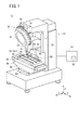
図1において、加工システム10は、主軸18に取り付けた切削工具16によりワークW(図2参照)を加工する工作機械12と、工作機械12を制御する制御装置14とを備える。
In FIG. 1, the
工作機械12は、切削工具16が取り付けられる主軸18と、主軸18を回転駆動する主軸頭20と、主軸頭20を上下方向(Z方向)に移動させるコラム22と、ワークWを固定するためのテーブル24と、テーブル24をZ方向に直交する水平2方向(X方向及びY方向)に移動させるテーブル駆動装置26とを備える。
The
切削工具16は、工具ホルダ28に保持されており、主軸18に着脱可能な工具ホルダ28を介して主軸18に取り付けられる。本実施形態では、工作機械12は、主軸18に取り付ける切削工具16を自動工具交換装置30により交換可能なマシニングセンタとして構成されている。自動工具交換装置30は、各々が工具ホルダ28に保持された複数の切削工具16を収納(保持)可能なツールマガジン32を有する。
The
複数の切削工具16は、少なくとも、ヘール工具を含む。ヘール工具は、非回転で切削を行う工具(固定工具)であり、切れ刃部の正面を常に切削方向に向けて加工する方式であるヘール加工を行うための切削工具である。以下、ヘール工具としての切削工具16を「切削工具16a」と表記する。後述するように、切削工具16aは、主軸位相割出し装置56の一構成要素であり、第2嵌合部76(図4参照)を有する。第2嵌合部76の詳細については後述する。
The plurality of
複数の切削工具16は、他の種類の工具として、例えば、ドリル、エンドミル、ヘール工具、トリマ等を含む。複数の切削工具16は、形状、大きさ等が異なる複数のヘール工具を含んでもよい。なお、工作機械12の構成は、マシニングセンタに限られない。工作機械12は、ヘール加工専用の工作機械として構成されてもよい。
The plurality of
主軸18は、Z方向に平行な主軸回転軸心を中心に回転可能に主軸頭20に支持されている。上述した切削工具16は、当該切削工具16を保持する工具ホルダ28が主軸18の先端部に設けられた装着穴に挿入されることによって、主軸18に取り付けられる。主軸18に切削工具16が取り付けられた状態で、主軸18と切削工具16とは軸心周りの相対回転が阻止される。
The
図2に示すように、主軸頭20は、主軸18を回転駆動する主軸モータ34を有する。主軸モータ34は、主軸18にエンドミル等の回転工具を取り付けた切削作業に際しては連続的に高速回転するスピンドルモータとして用いられるが、ヘール工具のような固定工具を取り付けた切削作業に際しては、主軸18の位相(回転位置)を制御するために用いられる。
As shown in FIG. 2, the
主軸モータ34には、主軸モータ34の回転位置(位相)を検出する位置検出器35(ロータリエンコーダ)が設けられている。位置検出器35は、回転速度を検出する速度検出器としての機能も有する。
The
コラム22は、主軸頭20をZ方向に沿って移動させる昇降機構としてのZ軸送り機構36と、Z軸送り機構36を駆動するZ軸用モータ38とを有する。Z軸用モータ38には、Z軸用モータ38の回転位置を検出する位置検出器39が設けられている。
The
図1において、テーブル24は、主軸18の下方に配置されている。テーブル24の上面24aには、複数の直線状のロック溝40が間隔を置いて形成されている。ワークWは、図示しないワーク固定治具を介してテーブル24に固定される。ワーク固定治具は、ロック溝40を利用してテーブル24の上面24aに固定できるように構成されている。
In FIG. 1, the table 24 is disposed below the
テーブル24は、テーブル駆動装置26によって支持されている。テーブル駆動装置26は、テーブル24をX方向に移動させる第1スライド部42と、テーブル24をX方向に直交するY方向に移動させる第2スライド部44とを有する。テーブル24は、第1スライド部42によってX方向にスライド可能に支持されている。
The table 24 is supported by a
図2において、第1スライド部42は、テーブル24をX方向に移動させるX軸送り機構46と、X軸送り機構46を駆動するX軸用モータ48とを有し、第2スライド部44によってY方向にスライド可能に支持されている。X軸用モータ48には、X軸用モータ48の回転位置を検出する位置検出器49が設けられている。
In FIG. 2, the
第2スライド部44は、第1スライド部42をY方向に移動させるY軸送り機構50と、Y軸送り機構50を駆動するY軸用モータ52とを有する。Y軸用モータ52には、Y軸用モータ52の回転位置を検出する位置検出器53が設けられている。
The
このように構成されるテーブル駆動装置26により、テーブル24を水平面で互いに直交する2方向に移動することができる。
With the
本実施形態の工作機械12では、X軸送り機構46により、主軸18とテーブル24とのX方向の相対移動を実現する送り軸(第1送り軸)が構成されている。以下、この送り軸を「X方向送り軸」という。また、Y軸送り機構50により、主軸18とテーブル24とのY方向の相対移動を実現する送り軸(第2送り軸)が構成されている。以下、この送り軸を「Y方向送り軸」という。また、Z軸送り機構36により、主軸18とテーブル24とのZ方向の相対移動を実現する送り軸が構成されている。以下、この送り軸を「Z方向送り軸」という。
In the
このように、本実施形態の場合、工作機械12は、互いに直交する3方向(XYZ方向)の送り軸を有する、いわゆる3軸加工機として構成されている。なお、工作機械12は、4つ以上の送り軸を有していてもよい。
Thus, in the case of the present embodiment, the
工作機械12において、Z方向送り軸を主軸頭20ではなくテーブル駆動装置26に設け、テーブル駆動装置26によりテーブル24を直交3方向に移動させるように構成してもよい。すなわち、テーブル駆動装置26が直交3方向の送り軸を構成してもよい。あるいは、X方向送り軸及びY方向送り軸をテーブル駆動装置26ではなく主軸頭20に設け、主軸頭20により主軸18を直交3方向に移動させるようにしてもよい。すなわち、主軸頭20が直交3方向の送り軸を構成してもよい。
In the
制御装置14は、加工プログラムに従ってワークWに対し所望の加工を行うように工作機械12を数値制御する数値制御装置である。制御装置14は、制御装置14自体の動作を統括制御するプロセッサ、システムプログラムが格納されたROM、各種情報の書込み・読出しが可能なRAM(以下、「記憶部54」という)等を有する。記憶部54には、インターフェース等を介して読み込まれ又は入力された加工プログラム等が記憶される。加工プログラムは、ワークWに対して所望の切削加工を行うようにコンピュータに対する命令を記述したものである。
The
制御装置14は、加工プログラムに従って、主軸モータ34及び各送り軸用のモータ38、48、52を駆動制御する。この場合、制御装置14は、主軸モータ34に設けられた位置検出器35からのフィードバック信号を受け取りつつ、主軸モータ34を数値制御する。また、制御装置14は、各送り軸用のモータ38、48、52に設けられた位置検出器39、49、53からのフィードバック信号を受け取りつつ、各モータ38、48、52を数値制御する。このような制御装置14によって、工作機械12の主軸18の位相と、テーブル24の位置とが精密に制御されながら、主軸18に取り付けた切削工具16によってワークWに対する加工が行われる。
The
図1において、本実施形態に係る工作機械12の主軸位相割出し装置56は、テーブル24に取り付け可能に構成されたガイドレール58と、ガイドレール58上を走行可能な位相割出し用治具60とを備える。主軸位相割出し装置56は、さらに、上述した切削工具16a及び制御装置14を備える。
In FIG. 1, the spindle
図3に示すように、本実施形態において、ガイドレール58は、固定用治具62を介して、テーブル24の上面24aに固定可能である。ガイドレール58は、直線状に延在するレール溝64を有する。レール溝64の上下両端部には、レール溝64の延在方向に沿ってガイド溝66が形成されている。このレール溝64の延在方向に沿って、位相割出し用治具60がスライド可能である。
As shown in FIG. 3, in this embodiment, the
位相割出し用治具60の、レール溝64に挿入される基部側の上下両端部には、ガイド溝66に挿入可能であり且つガイド溝66に沿って摺動可能なガイド突起68が設けられている。これにより、レール溝64と垂直な方向に位相割出し用治具60が外れることを防止しつつ、レール溝64の延在方向への位相割出し用治具60のスムーズな移動を可能としている。
位相割出し用治具60と切削工具16aとの後述する嵌合の際に切削工具16aの先端部に設けられた切れ刃部17がテーブル24の上面24aに接触することを回避するために、ガイドレール58は、テーブル24の上面24aから所定高さだけ高い位置で位相割出し用治具60を保持するように構成されている。
In order to avoid that the
具体的に、図3では、テーブル24の上面24aに固定用治具62が固定されており、この固定用治具62にガイドレール58が固定されている。固定用治具62は、テーブル24に設けられたロック溝40に係合可能な係合部を有し、当該係合部がロック溝40に係合することによりテーブル24に強固に固定される。ガイドレール58は、固定用治具62の高さ分だけ、テーブル24の上面24aに対して高い位置に保持される。なお、固定用治具62に代えて、ガイドレール58自体の下方部の厚さを大きくするとともに、当該下方部を直接テーブル24に固定できるように構成してもよい。
Specifically, in FIG. 3, a fixing
ガイドレール58は、X方向送り軸の動作方向又はY方向送り軸の動作方向と平行に取り付けて固定可能である。図3において、ガイドレール58は、テーブル24上に、X方向送り軸の動作方向と平行に取り付けられている。このため、位相割出し用治具60は、X方向送り軸の動作方向と平行にスライド可能である。なお、Y方向送り軸の動作方向と平行にガイドレール58が取り付けられた場合、位相割出し用治具60は、Y方向送り軸の動作方向と平行にスライド可能である。
The
位相割出し用治具60には、第1嵌合部70が設けられている。本実施形態では、第1嵌合部70は、溝部72と、溝部72の両側に隣接した2つの第1平坦部74とを有する。図3において、2つの第1平坦部74は、同一平面上に存在する。なお、2つの第1平坦部74は、互いに平行な又は傾斜した異なる平面上に存在してもよい。
The
図3に示す取付け状態(位相割出し用治具60を保持したガイドレール58がテーブル24に取り付けられた状態)で、溝部72及び第1平坦部74は、Z方向と平行に延在している。溝部72は、円弧状(図示例では半円状)に形成されている。溝部72は、半円に満たない円弧状溝であってもよい。
In the attached state shown in FIG. 3 (the state where the
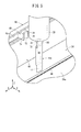
図4に示すように、切削工具16aには、上述した第1嵌合部70に嵌合可能な第2嵌合部76が設けられている。第2嵌合部76は、切削工具16aのシャンク部19(切削工具16aの基端部側の胴体部)に形成されている。第2嵌合部76は、第1嵌合部70と嵌合した状態で、位相割出し用治具60に対する切削工具16aの軸心周りの回転が規制(阻止)されるように形成されている。
As shown in FIG. 4, the cutting
図4において、第2嵌合部76は、切削工具16aの切れ刃部17が形成された周方向位置と同じ周方向位置に形成されているが、切れ刃部17とは異なる周方向位置に第2嵌合部76が形成されてもよい。切削工具16aにおける第2嵌合部76と切れ刃部17の周方向位置関係は、制御装置14の記憶部54(図1参照)に記憶されている。
In FIG. 4, the second
本実施形態では、第2嵌合部76は、第1嵌合部70の溝部72に適合(合致)する形状をもつ凸部78と、凸部78の両側に隣接した2つの第2平坦部80とを有する。図4において、2つの第2平坦部80は、同一平面上に存在する。なお、上述した2つの第1平坦部74が互いに平行な又は傾斜した異なる平面上に存在する場合には、2つの第2平坦部80は、互いに平行な又は傾斜した異なる平面上に存在してもよい。
In the present embodiment, the second
凸部78及び第2平坦部80は、切削工具16aの長さ方向、すなわちZ方向と平行に延在している。凸部78は、溝部72と同一形状の円弧状(図示例では半円状)に形成されている。凸部78は、半円に満たない円弧状溝であってもよい。
The
本実施形態において、第2嵌合部76は、シャンク部19の外周面に対して窪んだ形状に形成されている。なお、第2嵌合部76は、シャンク部19の外周面に対して隆起した形状に形成されていてもよい。
In the present embodiment, the second
上述したガイドレール58の長さは、第1嵌合部70と第2嵌合部76とが嵌合する際の位相割出し用治具60の変位(第1嵌合部70と第2嵌合部76との嵌合方向に垂直な方向への変位)を許容するように設定されていればよい。ガイドレール58は、図3に示すようにある程度長尺であってもよく、ガイドレール58が設置される方向と平行に動作する送り軸(本実施形態では、X方向送り軸)の可動範囲と同程度の長さを有していてもよい。但し、ガイドレール58は、当該送り軸の可動範囲を超える長さを有している必要はない。
The length of the
次に、上記のように構成された主軸位相割出し装置56の作用及び効果を説明する。
Next, the operation and effect of the spindle
図1において、工作機械12の主軸18にはヘール工具としての切削工具16aが取り付けられているものとする。切削工具16aによりワークWに対して加工を行う前に、主軸位相割出し装置56により、以下のようにして主軸18の位相を割り出す。
In FIG. 1, it is assumed that a
まず、図3のように、テーブル24上に、Z方向に直交する2つの送り軸の一方(本実施形態ではX方向送り軸)の動作方向と平行にガイドレール58を取り付ける。本実施形態では、固定用治具62を介してテーブル24の上面24aにガイドレール58を取り付けて固定する。また、ガイドレール58に位相割出し用治具60を取り付ける。これにより、位相割出し用治具60は、力が加わればガイドレール58を取り付けた方向の送り軸(本実施形態ではX方向送り軸)と平行に動作可能な状態になる。なお、位相割出し用治具60が取り付けられた状態のガイドレール58をテーブル24に取り付けてもよい。
First, as shown in FIG. 3, the
次に、オペレータは、図示しない操作盤で工作機械12を操作して、図5のように、位相割出し用治具60の正面に切削工具16aが位置するように、切削工具16aと位相割出し用治具60との相対位置を調整する。また、オペレータは、操作盤で工作機械12を操作して、位相割出し用治具60の第1嵌合部70と切削工具16aの第2嵌合部76とが概ね向き合うように切削工具16aを回転させる。
Next, the operator operates the
次に、加工システム10は、制御装置14による制御作用下に、ガイドレール58を取り付けた方向の送り軸(X方向送り軸)と垂直な方向の送り軸(Y方向送り軸)を駆動制御して、図6のように、第1嵌合部70と第2嵌合部76とが嵌合するように、位相割出し用治具60を切削工具16aに押し付ける。第1嵌合部70と第2嵌合部76の嵌合の際、位相割出し用治具60はガイドレール58に沿って動くことが可能である。従って、嵌合に伴う過大な負荷が切削工具16a及び主軸18に掛かることを防止できる。
Next, the
本実施形態では、第1嵌合部70と第2嵌合部76の嵌合の際にテーブル24の上面24aに切削工具16aの先端(切れ刃部17)が接触しないように、位相割出し用治具60は、固定用治具62で嵩上げされたガイドレール58に支持されることで、テーブル24の上面24aから適度に離間している。これにより、テーブル24の上面24aと切削工具16aの切れ刃部17との干渉が回避され、第1嵌合部70と第2嵌合部76の嵌合を支障なく行うことができる。なお、上述したように、固定用治具62で嵩上げする代わりに、位相割出し用治具60の下方部の厚さを大きくすることで、テーブル24の上面24aと切削工具16aの切れ刃部17との干渉が回避されるようにしてもよい。
In the present embodiment, the phase indexing is performed so that the tip (cutting edge portion 17) of the
第1嵌合部70と第2嵌合部76とが嵌合を開始するときに、図7Aのように、第2嵌合部76が、第1嵌合部70と正確に嵌合する方向に対して傾いている場合、切削工具16aは、位相割出し用治具60によって回転方向の力を受けるように押される。これにより、第1嵌合部70と第2嵌合部76とが正確に嵌合するように(第2嵌合部76が第1嵌合部70の形状に倣うように)、切削工具16aは強制的に回転させられる。本実施形態の場合、具体的には、第1嵌合部70の一方の第1平坦部74が第2嵌合部76の一方の第2平坦部80を押すことで、図7Aの矢印A方向に切削工具16aが回転動作する。
When the first
上述した切削工具16aの回転により、図7Bのように、第1嵌合部70の溝部72及び第1平坦部74によって、第2嵌合部76の凸部78及び第2平坦部80が拘束される。より具体的には、第1嵌合部70と第2嵌合部76とが互いに嵌合した状態では、第1嵌合部70の溝部72と第2嵌合部76の凸部78とが当接し合うとともに、第1嵌合部70の第1平坦部74と第2嵌合部76の第2平坦部80とが当接し合う。
Due to the rotation of the
これにより、第2嵌合部76は、第1嵌合部70との嵌合によって異なる2面が拘束された状態になる。この場合、凸部78が1つの面であり、2つの第2平坦部80がもう1つの面である。なお、本実施形態では、2つの第2平坦部80は、同一平面上に存在するため、1つの面として扱っている。2つの第2平坦部80が平行又は傾斜した異なる面に存在する場合、第2嵌合部76は、第1嵌合部70との嵌合によって3面が拘束されることになる。
Thereby, the 2nd
このような第1嵌合部70と第2嵌合部76との嵌合の結果、切削工具16aは位相割出し用治具60に対して特定の位相で回転不可能な状態となり、切削工具16aの位相が定まる。
As a result of the fitting between the first
切削工具16aの回転に伴って、切削工具16aが相対回転不可能に取り付けられた主軸18も回転動作する。制御装置14は、切削工具16aの位相が定まった状態(第1嵌合部70と第2嵌合部76とが完全に嵌合した状態)での主軸18の位相を、主軸モータ34に設けられた位置検出器35(図2参照)から読み取る。制御装置14は、読み取った主軸18の位相を主軸基準位相として、記憶部54に記憶する。これにより、主軸18の位相の割出しが完了する。主軸18の位相を割り出したら、テーブル24からガイドレール58及び位相割出し用治具60を取り外す。
Along with the rotation of the
なお、制御装置14は、第1嵌合部70と第2嵌合部76とがちょうど嵌合した時点で、X方向送り軸及びY方向送り軸のうち位相割出し用治具60の可動方向と垂直方向に動作する送り軸(本実施形態の場合、Y方向送り軸)の駆動を停止するのがよい。これにより、第1嵌合部70と第2嵌合部76との嵌合時に切削工具16a及び主軸18に過大な負荷が掛かることを回避することができる。この場合、X方向送り軸及びY方向送り軸のうち位相割出し用治具60の可動方向と垂直方向に動作する送り軸について、第1嵌合部70と第2嵌合部76とが嵌合するときの座標値を予め取得し、当該座標値を制御装置14の記憶部54に記憶させておく。
The
この場合の座標値の取得方法は、特に限定されず、既知の方法を採用することができる。例えば、切削工具16aに代えて、切削工具16aに近似する形状のタッチプローブを主軸18に取り付ける。そして、X方向送り軸及びY方向送り軸のうち位相割出し用治具60の可動方向と垂直方向に動作する送り軸を駆動して、当該タッチプローブを位相割出し用治具60に接触させ、接触時の座標値を読み取る。これにより、上記座標値を計測することができる。あるいは、切削工具16aと位相割出し用治具60との接触時の負荷を送り軸のモータ(X軸用モータ48又はY軸用モータ52)に流れる電流値で監視することによっても、上記座標値を計測することができる。
The coordinate value acquisition method in this case is not particularly limited, and a known method can be employed. For example, instead of the
以上のように、主軸位相割出し装置56により主軸18の位相(主軸基準位相)を割り出すことができる。上述したように、制御装置14は、切削工具16aにおける切れ刃部17と第2嵌合部76との周方向位置関係を記憶部54に記憶している。従って、制御装置14は、第1嵌合部70と第2嵌合部76とが嵌合した時点での主軸18の位相と、切削工具16aの切れ刃部17の周方向位置とを関連付けて記憶部54に記憶している。そこで、切削工具16aを用いてワークWに切削加工を行う際、制御装置14は、記憶部54に記憶した主軸18の位相(上記主軸基準位相)に基づいて、主軸18の角度(回転位置)を制御する。これにより、ワークWに対して精度よく切削加工(ヘール加工)を行うことができる。
As described above, the phase of the main shaft 18 (main shaft reference phase) can be determined by the main shaft
なお、加工システム10のように自動工具交換装置30を備え、且つ複数のヘール工具を交換可能である場合、主軸18にヘール工具が取り付けられる毎に、主軸位相割出し装置56を用いて主軸18の位相を割り出してもよい。この場合、ガイドレール58(下方部の厚さが大きいガイドレール58を含む)は、常時、テーブル24に取り付けられていてもよい。あるいは、ガイドレール58は、テーブル24に取り外し不可能に固着されていてもよい。
When the
以上説明したように、本実施形態に係る主軸位相割出し装置56によれば、位相割出し用治具60に対して切削工具16aを相対移動させて、第1嵌合部70と第2嵌合部76とを嵌合させる際、切削工具16aが取り付けられた主軸18は、位相割出し用治具60からの力を受けて回転動作する。これにより、位相割出し用治具60に対して切削工具16aは所定の向きに拘束され、その時点での主軸18の位相を制御装置14が記憶する。従って、主軸位相割出し装置56を用いることにより、安価且つ切削工具16a先端の切れ刃部17を破損することなく、切削工具16aが取り付けられた工作機械12の主軸18の位相を簡単に割り出すことができる。
As described above, according to the spindle
本実施形態では、ガイドレール58は、テーブル24の上面24aに取り付け可能であるため、ガイドレール58を容易に設置することができる。
In this embodiment, since the
第2嵌合部76は、第1嵌合部70と嵌合したときに2面以上が拘束される形状(本実施形態では凸形状)であるため、第1嵌合部70と第2嵌合部76の嵌合によって切削工具16aを正確に拘束し、主軸18の位相を確実に割り出すことができる。
Since the second
本実施形態では、第1嵌合部70は、溝部72と、溝部72に隣接した第1平坦部74とを有し、第2嵌合部76は、溝部72に適合する凸部78と、凸部78に隣接した第2平坦部80とを有する。この構成によれば、第1嵌合部70と第2嵌合部76との嵌合の際、溝部72と凸部78とが当接するとともに、第1平坦部74と第2平坦部80とが当接することにより、切削工具16aを正確に拘束し、主軸18の位相を確実に割り出すことができる。特に、溝部72及び凸部78は円弧状に形成されているため、第1嵌合部70と第2嵌合部76とをスムーズに嵌合させることができる。
In the present embodiment, the first
本実施形態では、ガイドレール58がテーブル24に取り付けられた状態で、位相割出し用治具60は、X方向送り軸又はY方向送り軸の送り動作方向と平行に動作可能である。これにより、X方向送り軸又はY方向送り軸のうち位相割出し用治具60の可動方向と垂直方向の送り軸を動作させることで、第1嵌合部70と第2嵌合部76が嵌合するように位相割出し用治具60を簡単に切削工具16aに押し付けることができる。
In the present embodiment, the
本実施形態では、制御装置14は、X方向送り軸又はY方向送り軸のうち位相割出し用治具60の可動方向と垂直方向に動作する送り軸について、第1嵌合部70と第2嵌合部76とが嵌合するときの座標値を記憶している。これにより、第1嵌合部70と第2嵌合部76との嵌合の際に、切削工具16a及び主軸18に大きな負荷が掛かることを防止することができる。
In the present embodiment, the
第1嵌合部70及び第2嵌合部76は、嵌合時に2面以上が拘束される凹凸形状であればよく、例えば、図8〜図10に示す変形例が挙げられる。
The 1st
図8に示す位相割出し用治具60及び切削工具16aにおける第1嵌合部70a及び第2嵌合部76aは、上述した第1嵌合部70及び第2嵌合部76(図3及び図4)とは凹凸の関係が逆になっている。すなわち、図8において、第1嵌合部70aは、円弧状の凸部82と、凸部82の両側に隣接した2つの第1平坦部74とを有する。第2嵌合部76aは、第1嵌合部70aの凸部82に適合する円弧状の溝部86と、溝部86の両側に隣接した2つの第2平坦部80とを有する。このような第1嵌合部70a及び第2嵌合部76aによっても、嵌合時に2面以上が拘束されることで切削工具16aの位相を正確に定めることができる。
The first
図9に示す位相割出し用治具60の第1嵌合部70bは、V字状の溝部90と、溝部90の両側に隣接した2つの第1平坦部74とを有する。図9に示す切削工具16aの第2嵌合部76bは、第1嵌合部70bの溝部90に適合するV字状の凸部92と、凸部92の両側に隣接した2つの第2平坦部80とを有する。このような第1嵌合部70b及び第2嵌合部76bによっても、嵌合時に2面以上が拘束されることで切削工具16aの位相を正確に定めることができる。なお、第1嵌合部70bにおいて、V字状の溝部90に代えてV字状の凸部92が設けられ、第2嵌合部76bにおいて、V字状の凸部92に代えてV字状の溝部90が設けられてもよい。
The first
図10に示す位相割出し用治具60の第1嵌合部70cは、台形状の溝部94と、溝部94の両側に隣接した2つの第1平坦部74とを有する。図10に示す切削工具16aの第2嵌合部76cは、第1嵌合部70cの溝部94に適合する台形状の凸部96と、凸部96の両側に隣接した2つの第2平坦部80とを有する。このような第1嵌合部70c及び第2嵌合部76cによっても、嵌合時に2面以上が拘束されることで切削工具16aの位相を正確に定めることができる。なお、第1嵌合部70cにおいて、台形状の溝部94に代えて台形状の凸部96が設けられ、第2嵌合部76cにおいて、台形状の凸部96に代えて台形状の溝部94が設けられてもよい。
10 includes a
本発明は上述した実施形態に限定されるものではなく、本発明の要旨を逸脱しない範囲において、種々の改変が可能である。 The present invention is not limited to the above-described embodiments, and various modifications can be made without departing from the gist of the present invention.
12…工作機械 14…制御装置
16、16a…切削工具 18…主軸
54…記憶部 56…主軸位相割出し装置
58…ガイドレール 60…位相割出し用治具
70、70a〜70c…第1嵌合部 74…第1平坦部
76、76a〜76c…第2嵌合部 72、86、90、94…溝部
78、92、96…凸部 80…第2平坦部
DESCRIPTION OF
Claims (7)
前記ガイドレール上を走行可能であり、凹状又は凸状の第1嵌合部が設けられた位相割出し用治具と、
前記工作機械の主軸に取り付けられ、前記第1嵌合部に嵌合可能な第2嵌合部が設けられた切削工具と、
前記第1嵌合部と前記第2嵌合部とが嵌合した時点での前記主軸の位相を記憶する制御装置と、を備え、
前記第1嵌合部と前記第2嵌合部との嵌合時に前記切削工具の回転が拘束されるように、前記第1嵌合部と前記第2嵌合部が形成されている、
ことを特徴とする工作機械の主軸位相割出し装置。 A guide rail that can be attached to or fixed to a table of a machine tool;
A phase indexing jig that is capable of traveling on the guide rail and provided with a concave or convex first fitting portion;
A cutting tool attached to the spindle of the machine tool and provided with a second fitting portion that can be fitted to the first fitting portion;
A controller for storing a phase of the main shaft at the time when the first fitting portion and the second fitting portion are fitted,
The first fitting portion and the second fitting portion are formed so that the rotation of the cutting tool is constrained when the first fitting portion and the second fitting portion are fitted.
A spindle phase indexing device for machine tools.
前記ガイドレールは、前記テーブルの上面に取り付け可能である、
ことを特徴とする工作機械の主軸位相割出し装置。 In the spindle phase indexing device for a machine tool according to claim 1,
The guide rail can be attached to the upper surface of the table.
A spindle phase indexing device for machine tools.
前記第2嵌合部は、前記第1嵌合部と嵌合したときに2面以上が拘束される凹形状又は凸形状である、
ことを特徴とする工作機械の主軸位相割出し装置。 In the spindle phase indexing device for a machine tool according to claim 1 or 2,
The second fitting portion is a concave shape or a convex shape in which two or more surfaces are restrained when fitted to the first fitting portion.
A spindle phase indexing device for machine tools.
前記第1嵌合部及び前記第2嵌合部の一方は、溝部と、前記溝部に隣接した第1平坦部とを有し、
前記第1嵌合部及び前記第2嵌合部の他方は、前記溝部に適合する凸部と、前記凸部に隣接した第2平坦部とを有する、
ことを特徴とする工作機械の主軸位相割出し装置。 The spindle phase indexing device for a machine tool according to any one of claims 1 to 3,
One of the first fitting part and the second fitting part has a groove part and a first flat part adjacent to the groove part,
The other of the first fitting part and the second fitting part has a convex part that fits the groove part, and a second flat part adjacent to the convex part,
A spindle phase indexing device for machine tools.
前記溝部及び前記凸部は、円弧状に形成されている、
ことを特徴とする工作機械の主軸位相割出し装置。 The spindle phase indexing device for a machine tool according to claim 4,
The groove and the convex are formed in an arc shape,
A spindle phase indexing device for machine tools.
前記工作機械は、前記主軸の回転中心に直交する方向に動作する第1送り軸と、前記回転中心及び前記第1送り軸に直交する方向に動作する第2送り軸とを有し、
前記ガイドレールが前記テーブルに取り付けられた状態で、前記位相割出し用治具は、前記第1送り軸又は前記第2送り軸の送り動作方向と平行に動作可能である、
ことを特徴とする工作機械の主軸位相割出し装置。 In the spindle phase indexing device for a machine tool according to any one of claims 1 to 5,
The machine tool has a first feed shaft that operates in a direction orthogonal to the rotation center of the main shaft, and a second feed shaft that operates in a direction orthogonal to the rotation center and the first feed shaft,
With the guide rail attached to the table, the phase indexing jig is operable in parallel with the feed operation direction of the first feed shaft or the second feed shaft.
A spindle phase indexing device for machine tools.
前記制御装置は、前記第1送り軸及び前記第2送り軸のうち前記位相割出し用治具の可動方向と垂直方向に動作する送り軸について、前記第1嵌合部と前記第2嵌合部とが嵌合するときの座標値を記憶している、
ことを特徴とする工作機械の主軸位相割出し装置。 The spindle phase indexing device for a machine tool according to claim 6,
The control device includes the first fitting portion and the second fitting of a feed shaft that operates in a direction perpendicular to a movable direction of the phase indexing jig among the first feed shaft and the second feed shaft. Stores the coordinate value when fitting with the part,
A spindle phase indexing device for machine tools.
Priority Applications (5)
| Application Number | Priority Date | Filing Date | Title |
|---|---|---|---|
| JP2016030217A JP6301985B2 (en) | 2016-02-19 | 2016-02-19 | Spindle phase indexing device for machine tools |
| DE102017001297.0A DE102017001297B4 (en) | 2016-02-19 | 2017-02-10 | Device for indexing a spindle phase for a machine tool |
| US15/429,438 US9902031B2 (en) | 2016-02-19 | 2017-02-10 | Spindle phase indexing device for machine tool |
| CN201720142321.4U CN206764463U (en) | 2016-02-19 | 2017-02-16 | The main shaft phase indexing means of lathe |
| CN201710083944.3A CN107097100B (en) | 2016-02-19 | 2017-02-16 | The main shaft phase indexing means of lathe |
Applications Claiming Priority (1)
| Application Number | Priority Date | Filing Date | Title |
|---|---|---|---|
| JP2016030217A JP6301985B2 (en) | 2016-02-19 | 2016-02-19 | Spindle phase indexing device for machine tools |
Publications (2)
| Publication Number | Publication Date |
|---|---|
| JP2017144536A JP2017144536A (en) | 2017-08-24 |
| JP6301985B2 true JP6301985B2 (en) | 2018-03-28 |
Family
ID=59522137
Family Applications (1)
| Application Number | Title | Priority Date | Filing Date |
|---|---|---|---|
| JP2016030217A Active JP6301985B2 (en) | 2016-02-19 | 2016-02-19 | Spindle phase indexing device for machine tools |
Country Status (4)
| Country | Link |
|---|---|
| US (1) | US9902031B2 (en) |
| JP (1) | JP6301985B2 (en) |
| CN (2) | CN107097100B (en) |
| DE (1) | DE102017001297B4 (en) |
Families Citing this family (4)
| Publication number | Priority date | Publication date | Assignee | Title |
|---|---|---|---|---|
| JP6301985B2 (en) * | 2016-02-19 | 2018-03-28 | ファナック株式会社 | Spindle phase indexing device for machine tools |
| JP6881725B2 (en) * | 2016-05-27 | 2021-06-02 | 中村留精密工業株式会社 | Work processing method, spindle angle correction device and compound lathe |
| JP6959279B2 (en) * | 2019-02-28 | 2021-11-02 | ファナック株式会社 | Machine tools and machining change methods |
| CN114102156B (en) * | 2021-11-20 | 2024-02-23 | 济源市腾辉金属构件有限公司 | Machining tool for hammerhead of precision forging machine and using method of machining tool |
Family Cites Families (22)
| Publication number | Priority date | Publication date | Assignee | Title |
|---|---|---|---|---|
| US3619013A (en) * | 1970-02-16 | 1971-11-09 | Giddings & Lewis | Preloaded hydrostatic way-bearing |
| JPS5714875B2 (en) * | 1973-03-23 | 1982-03-26 | ||
| JPS5199887U (en) * | 1975-02-08 | 1976-08-11 | ||
| JPS56102449A (en) * | 1979-12-31 | 1981-08-15 | Fanuc Ltd | Device for controlling orientation of main spindle |
| IT1155587B (en) * | 1982-07-29 | 1987-01-28 | Comau Spa | REFERENCE AND LOCKING DEVICE OF TOOL HOLDERS FOR TURNING OR MILLING OR OTHER ON MOBILE SLIDES WITH INTERNAL SPINDLE OF A LATHE WORK CENTER |
| DE3404497A1 (en) * | 1984-02-09 | 1985-08-29 | Kelch Gmbh + Co Werkzeugmaschinenfabrik, 7060 Schorndorf | Method and apparatus for the rotary alignment of a machine tool work spindle |
| JPS60146634U (en) * | 1984-03-07 | 1985-09-28 | ダイキン工業株式会社 | Positioning structure of position indexing device |
| JPS6195854A (en) * | 1984-10-12 | 1986-05-14 | Hitachi Seiki Co Ltd | Indexing device |
| CN2059615U (en) * | 1989-09-25 | 1990-07-25 | 陈添进 | Cam adjusting device for controlling cutter stroke |
| JP2716317B2 (en) * | 1992-06-19 | 1998-02-18 | 株式会社牧野フライス製作所 | Cutting method |
| JP3626834B2 (en) * | 1997-05-26 | 2005-03-09 | オークマ株式会社 | Angular phase difference detection method for fixed tool edges |
| JP3167644B2 (en) * | 1997-06-20 | 2001-05-21 | 株式会社森精機製作所 | Tool spindle fixing device for compound machine tools |
| DE10306832A1 (en) * | 2002-10-18 | 2004-04-29 | Schumag Ag | Feed apparatus for workpiece processing machine has at least one feed roller shaft mounted eccentrically in shaft receiver |
| US6929426B2 (en) * | 2003-02-19 | 2005-08-16 | Kennametal Inc. | Indexable cutting tool |
| JP4652873B2 (en) | 2005-04-06 | 2011-03-16 | オークマ株式会社 | Tool measurement method for machine tools |
| JP4549332B2 (en) * | 2006-09-29 | 2010-09-22 | 株式会社牧野フライス製作所 | Tool positioning method and apparatus |
| JP5342371B2 (en) * | 2009-08-19 | 2013-11-13 | 三菱重工業株式会社 | Tool rotation direction positioning method |
| JP5348169B2 (en) * | 2011-03-31 | 2013-11-20 | ブラザー工業株式会社 | Machine tools and tool holders |
| JP3183660U (en) * | 2013-03-13 | 2013-05-30 | ファナック株式会社 | Tool holder for mounting non-rotating tools of machining centers |
| CN104440097B (en) * | 2013-09-17 | 2017-01-11 | 富鼎电子科技(嘉善)有限公司 | Turning and milling combination feeding device, turning and milling combination machine tool and machining method implemented by same |
| CN203818112U (en) * | 2014-03-17 | 2014-09-10 | 上海涂思机电技术有限公司 | Corner processing cutting quantity regulating positioner |
| JP6301985B2 (en) * | 2016-02-19 | 2018-03-28 | ファナック株式会社 | Spindle phase indexing device for machine tools |
-
2016
- 2016-02-19 JP JP2016030217A patent/JP6301985B2/en active Active
-
2017
- 2017-02-10 US US15/429,438 patent/US9902031B2/en active Active
- 2017-02-10 DE DE102017001297.0A patent/DE102017001297B4/en active Active
- 2017-02-16 CN CN201710083944.3A patent/CN107097100B/en active Active
- 2017-02-16 CN CN201720142321.4U patent/CN206764463U/en not_active Withdrawn - After Issue
Also Published As
| Publication number | Publication date |
|---|---|
| CN206764463U (en) | 2017-12-19 |
| JP2017144536A (en) | 2017-08-24 |
| CN107097100A (en) | 2017-08-29 |
| DE102017001297A1 (en) | 2017-08-24 |
| US20170239766A1 (en) | 2017-08-24 |
| CN107097100B (en) | 2019-07-26 |
| US9902031B2 (en) | 2018-02-27 |
| DE102017001297B4 (en) | 2018-11-08 |
Similar Documents
| Publication | Publication Date | Title |
|---|---|---|
| JP6301985B2 (en) | Spindle phase indexing device for machine tools | |
| US9481049B2 (en) | Combined machining method and combined machining device | |
| JP5801346B2 (en) | Drilling device and drilling method | |
| JP5856212B2 (en) | Jig and processing system for supporting a workpiece rotatably with respect to a tool of a machine tool | |
| KR101396689B1 (en) | Machine tool | |
| JP6794868B2 (en) | Combined gear cutting equipment | |
| US8077327B2 (en) | Method for controlling a machine tool and apparatus therefor | |
| KR910018118A (en) | Air foil processing method | |
| JP7068317B2 (en) | How to control a machine tool | |
| US20180056465A1 (en) | Fluid ejection device | |
| JP6534571B2 (en) | Metal processing equipment and clamp jig | |
| US10500687B2 (en) | Machine tool | |
| JP2014087883A (en) | Method for measuring tool length, and machine tool | |
| JP6638736B2 (en) | Machine tool and cutting method | |
| JP4572133B2 (en) | Internal processing equipment for hollow workpieces | |
| JP3204456U (en) | Milling machine | |
| US10875136B2 (en) | Machine tool system and clamping method | |
| JP7057703B2 (en) | Machine Tools | |
| US11311953B2 (en) | Machine tool | |
| JPH0531639A (en) | Machining device for long workpiece | |
| JP6897395B2 (en) | Processing equipment | |
| JPH07241918A (en) | Blade stage for cutting presnel lens | |
| KR20200003009A (en) | Grinding machine | |
| JPH0617836U (en) | Work clamp device for automatic processing equipment for long products | |
| JP2017127926A (en) | Grindstone correction device, machine tool having the same and grindstone correction method |
Legal Events
| Date | Code | Title | Description |
|---|---|---|---|
| A977 | Report on retrieval |
Free format text: JAPANESE INTERMEDIATE CODE: A971007 Effective date: 20180125 |
|
| TRDD | Decision of grant or rejection written | ||
| A01 | Written decision to grant a patent or to grant a registration (utility model) |
Free format text: JAPANESE INTERMEDIATE CODE: A01 Effective date: 20180206 |
|
| A61 | First payment of annual fees (during grant procedure) |
Free format text: JAPANESE INTERMEDIATE CODE: A61 Effective date: 20180301 |
|
| R150 | Certificate of patent or registration of utility model |
Ref document number: 6301985 Country of ref document: JP Free format text: JAPANESE INTERMEDIATE CODE: R150 |