JP6301836B2 - Insulating heating module for auxiliary heating device - Google Patents
Insulating heating module for auxiliary heating device Download PDFInfo
- Publication number
- JP6301836B2 JP6301836B2 JP2014535072A JP2014535072A JP6301836B2 JP 6301836 B2 JP6301836 B2 JP 6301836B2 JP 2014535072 A JP2014535072 A JP 2014535072A JP 2014535072 A JP2014535072 A JP 2014535072A JP 6301836 B2 JP6301836 B2 JP 6301836B2
- Authority
- JP
- Japan
- Prior art keywords
- electrode
- heating module
- plate
- thermally conductive
- heating
- Prior art date
- Legal status (The legal status is an assumption and is not a legal conclusion. Google has not performed a legal analysis and makes no representation as to the accuracy of the status listed.)
- Active
Links
- 238000010438 heat treatment Methods 0.000 title claims description 58
- 239000011248 coating agent Substances 0.000 claims description 9
- 238000000576 coating method Methods 0.000 claims description 9
- 229910052782 aluminium Inorganic materials 0.000 claims description 7
- XAGFODPZIPBFFR-UHFFFAOYSA-N aluminium Chemical compound [Al] XAGFODPZIPBFFR-UHFFFAOYSA-N 0.000 claims description 7
- 229920000728 polyester Polymers 0.000 claims description 5
- 239000000853 adhesive Substances 0.000 claims description 3
- 230000001070 adhesive effect Effects 0.000 claims description 3
- 239000000463 material Substances 0.000 claims 1
- 229910052751 metal Inorganic materials 0.000 description 13
- 239000002184 metal Substances 0.000 description 13
- 239000011247 coating layer Substances 0.000 description 5
- 229910000838 Al alloy Inorganic materials 0.000 description 4
- 238000005485 electric heating Methods 0.000 description 4
- 230000000712 assembly Effects 0.000 description 3
- 238000000429 assembly Methods 0.000 description 3
- 229920001296 polysiloxane Polymers 0.000 description 3
- 238000004378 air conditioning Methods 0.000 description 2
- 239000012530 fluid Substances 0.000 description 2
- 238000009413 insulation Methods 0.000 description 2
- 238000004026 adhesive bonding Methods 0.000 description 1
- 238000005273 aeration Methods 0.000 description 1
- 238000005452 bending Methods 0.000 description 1
- 238000001816 cooling Methods 0.000 description 1
- 230000008021 deposition Effects 0.000 description 1
- 238000009422 external insulation Methods 0.000 description 1
- 239000010410 layer Substances 0.000 description 1
- 238000004519 manufacturing process Methods 0.000 description 1
- 238000013021 overheating Methods 0.000 description 1
- 239000011347 resin Substances 0.000 description 1
- 229920005989 resin Polymers 0.000 description 1
- 238000005507 spraying Methods 0.000 description 1
- 238000009423 ventilation Methods 0.000 description 1
Images


Classifications
-
- B—PERFORMING OPERATIONS; TRANSPORTING
- B60—VEHICLES IN GENERAL
- B60H—ARRANGEMENTS OF HEATING, COOLING, VENTILATING OR OTHER AIR-TREATING DEVICES SPECIALLY ADAPTED FOR PASSENGER OR GOODS SPACES OF VEHICLES
- B60H1/00—Heating, cooling or ventilating [HVAC] devices
- B60H1/22—Heating, cooling or ventilating [HVAC] devices the heat being derived otherwise than from the propulsion plant
- B60H1/2215—Heating, cooling or ventilating [HVAC] devices the heat being derived otherwise than from the propulsion plant the heat being derived from electric heaters
- B60H1/2225—Heating, cooling or ventilating [HVAC] devices the heat being derived otherwise than from the propulsion plant the heat being derived from electric heaters arrangements of electric heaters for heating air
-
- F—MECHANICAL ENGINEERING; LIGHTING; HEATING; WEAPONS; BLASTING
- F24—HEATING; RANGES; VENTILATING
- F24H—FLUID HEATERS, e.g. WATER OR AIR HEATERS, HAVING HEAT-GENERATING MEANS, e.g. HEAT PUMPS, IN GENERAL
- F24H1/00—Water heaters, e.g. boilers, continuous-flow heaters or water-storage heaters
- F24H1/0072—Special adaptations
- F24H1/009—Special adaptations for vehicle systems
-
- F—MECHANICAL ENGINEERING; LIGHTING; HEATING; WEAPONS; BLASTING
- F24—HEATING; RANGES; VENTILATING
- F24H—FLUID HEATERS, e.g. WATER OR AIR HEATERS, HAVING HEAT-GENERATING MEANS, e.g. HEAT PUMPS, IN GENERAL
- F24H3/00—Air heaters
- F24H3/02—Air heaters with forced circulation
- F24H3/04—Air heaters with forced circulation the air being in direct contact with the heating medium, e.g. electric heating element
- F24H3/0405—Air heaters with forced circulation the air being in direct contact with the heating medium, e.g. electric heating element using electric energy supply, e.g. the heating medium being a resistive element; Heating by direct contact, i.e. with resistive elements, electrodes and fins being bonded together without additional element in-between
- F24H3/0429—For vehicles
- F24H3/0435—Structures comprising heat spreading elements in the form of fins
-
- F—MECHANICAL ENGINEERING; LIGHTING; HEATING; WEAPONS; BLASTING
- F24—HEATING; RANGES; VENTILATING
- F24H—FLUID HEATERS, e.g. WATER OR AIR HEATERS, HAVING HEAT-GENERATING MEANS, e.g. HEAT PUMPS, IN GENERAL
- F24H9/00—Details
- F24H9/18—Arrangement or mounting of grates or heating means
- F24H9/1854—Arrangement or mounting of grates or heating means for air heaters
- F24H9/1863—Arrangement or mounting of electric heating means
- F24H9/1872—PTC
-
- H—ELECTRICITY
- H05—ELECTRIC TECHNIQUES NOT OTHERWISE PROVIDED FOR
- H05B—ELECTRIC HEATING; ELECTRIC LIGHT SOURCES NOT OTHERWISE PROVIDED FOR; CIRCUIT ARRANGEMENTS FOR ELECTRIC LIGHT SOURCES, IN GENERAL
- H05B3/00—Ohmic-resistance heating
-
- H—ELECTRICITY
- H05—ELECTRIC TECHNIQUES NOT OTHERWISE PROVIDED FOR
- H05B—ELECTRIC HEATING; ELECTRIC LIGHT SOURCES NOT OTHERWISE PROVIDED FOR; CIRCUIT ARRANGEMENTS FOR ELECTRIC LIGHT SOURCES, IN GENERAL
- H05B3/00—Ohmic-resistance heating
- H05B3/20—Heating elements having extended surface area substantially in a two-dimensional plane, e.g. plate-heater
- H05B3/22—Heating elements having extended surface area substantially in a two-dimensional plane, e.g. plate-heater non-flexible
- H05B3/26—Heating elements having extended surface area substantially in a two-dimensional plane, e.g. plate-heater non-flexible heating conductor mounted on insulating base
- H05B3/262—Heating elements having extended surface area substantially in a two-dimensional plane, e.g. plate-heater non-flexible heating conductor mounted on insulating base the insulating base being an insulated metal plate
-
- H—ELECTRICITY
- H05—ELECTRIC TECHNIQUES NOT OTHERWISE PROVIDED FOR
- H05B—ELECTRIC HEATING; ELECTRIC LIGHT SOURCES NOT OTHERWISE PROVIDED FOR; CIRCUIT ARRANGEMENTS FOR ELECTRIC LIGHT SOURCES, IN GENERAL
- H05B2203/00—Aspects relating to Ohmic resistive heating covered by group H05B3/00
- H05B2203/022—Heaters specially adapted for heating gaseous material
- H05B2203/023—Heaters of the type used for electrically heating the air blown in a vehicle compartment by the vehicle heating system
Landscapes
- Engineering & Computer Science (AREA)
- Physics & Mathematics (AREA)
- Thermal Sciences (AREA)
- Mechanical Engineering (AREA)
- Chemical & Material Sciences (AREA)
- Combustion & Propulsion (AREA)
- General Engineering & Computer Science (AREA)
- Air-Conditioning For Vehicles (AREA)
- Resistance Heating (AREA)
- Direct Air Heating By Heater Or Combustion Gas (AREA)
Description
本発明は、特に自動車の客室のための加熱、換気、および/または空調設備(HVAC)のための、補助加熱用放熱器の分野に関する。 The present invention relates to the field of auxiliary heating radiators, in particular for heating, ventilation and / or air conditioning (HVAC) for automobile cabins.
外部温度が低い時、および、特に冬には、一定の時間が、車が始動する時点と温かいエアが通気/除氷ノズルから出てくることができる時点との間で経過する。これは、車の熱機関の冷却回路の流体の温度が上がるのに要する時間によって生じ、この流体は、加熱用放熱器を用いて客室のエアを加熱するために使用される。この欠点を克服するために、熱的な加熱用放熱器に加えて、車両の電源により電力供給され、当該補助電気加熱装置を通過するエアをより迅速に加熱することを可能にする、補助電気加熱装置を取り付けることが提案されている。 When the external temperature is low, and especially in winter, a certain time elapses between when the car starts and when warm air can come out of the aeration / deicing nozzle. This is caused by the time required for the temperature of the fluid in the cooling circuit of the car's heat engine to rise, and this fluid is used to heat the cabin air using a heating radiator. In order to overcome this drawback, in addition to the thermal heating radiator, the auxiliary electric, which is powered by the vehicle's power supply and allows the air passing through the auxiliary electric heating device to be heated more quickly. It has been proposed to install a heating device.
特許出願WO2006073264により説明されているような、抵抗器、電極および放散器の間の構成要素の特別なアセンブリにより絶縁された少なくとも1つの熱放散棒状体からなる、複数の加熱モジュールのアセンブリにより構成されており、各モジュールは、取付フレームにより囲まれている、という補助電気加熱装置が知られている。 Consists of an assembly of a plurality of heating modules consisting of at least one heat dissipating rod that is insulated by a special assembly of components between resistors, electrodes and dissipators, as described by patent application WO2006073264 An auxiliary electric heating device is known in which each module is surrounded by a mounting frame.
しかしながら、これらの装置は、多くの構成要素のアセンブリを必要とし、それが非常に精密な調整、アセンブリの厳密な順序、および、結果的に、高い最終コストを含む、という欠点を有する。 However, these devices have the disadvantage that they require many component assemblies, which involve very precise adjustments, the exact order of assembly, and consequently high final costs.
これらのアセンブリの別の知られた欠点は、補助加熱装置の外部絶縁に関する。実際、2つの熱放散棒状体により構成された同じ加熱モジュールの正相と逆相との間に、または異なる相の2つの棒状体の間に、弱点がある。これは、金属のまたは電気的な導電性部分が加熱装置に接触すれば、そのとき、その金属の部分が、車両の電気回路の正しい機能を害する短絡回路を形成し得る、ということを表す。 Another known drawback of these assemblies relates to the external insulation of the auxiliary heating device. In fact, there is a weakness between the positive and negative phases of the same heating module constituted by two heat dissipating rods, or between two rods of different phases. This means that if a metal or electrically conductive part contacts the heating device, then that metal part can form a short circuit that impairs the correct functioning of the vehicle's electrical circuit.
さらに、ほとんどの場合における補助加熱装置のアセンブリは、5相、すなわち3つの正相および2つの逆相、を有する複数の加熱モジュールのアセンブリである。負荷が相の間で異なるため、このアセンブリは、不均一な熱挙動を形成するとともに、加熱モジュールの製造業者に各モジュールの電圧を他に対して非常に正確にチェックすることを強いる、という制限を有しており、これは、製造プロセスをより困難にする。 Furthermore, the auxiliary heating device assembly in most cases is an assembly of multiple heating modules having five phases: three normal and two reverse phases. Because the load is different between phases, this assembly creates uneven heat behavior and forces the heating module manufacturer to check each module's voltage very accurately against the others This makes the manufacturing process more difficult.
いかなる電気装置に関しても、構成要素は、起こり得る短絡回路を防ぐとともに正しい動作および最善の安全性を保証するために、部分的に絶縁されなければならない。 For any electrical device, the components must be partially insulated to prevent possible short circuits and to ensure correct operation and best safety.
本発明の目的は、前記に説明された従来技術の欠点を克服することである。 The object of the present invention is to overcome the drawbacks of the prior art described above.
この目的のために、本発明は、少なくとも1つの電気抵抗器が接触して配置された少なくとも1つの熱伝導性棒状体を備えた、エアの流れを加熱することを意図された補助加熱装置の加熱モジュールを提案する。熱伝導性棒状体は、部分的に電気的に絶縁されている。そのようなモジュールは、その少なくとも部分的な絶縁のために、安全性に関して確実かつ信頼できるやり方で、客室の急速加熱を保証する。なぜなら、短絡回路のリスクが除かれるからである。 For this purpose, the present invention relates to an auxiliary heating device intended to heat a flow of air with at least one thermally conductive rod arranged in contact with at least one electrical resistor. A heating module is proposed. The thermally conductive rod-like body is partially electrically insulated. Such a module ensures rapid heating of the passenger cabin in a reliable and reliable manner with respect to its at least partial insulation. This is because the risk of a short circuit is eliminated.
本発明の実施形態によれば、加熱モジュールは、好ましくは、正の温度係数(PTC)を有する少なくとも1つの抵抗要素により構成された抵抗器により分離された2つの熱伝導性棒状体から構成されている。熱生成要素として使用されるそのようなPTC抵抗要素は、要素の温度が上がるにつれて電気抵抗が増加するという事実により区別される。したがって、自己調整現象が形成される。 According to an embodiment of the invention, the heating module is preferably composed of two thermally conductive rods separated by a resistor composed of at least one resistive element having a positive temperature coefficient (PTC). ing. Such PTC resistive elements used as heat generating elements are distinguished by the fact that the electrical resistance increases as the temperature of the element increases. Therefore, a self-adjustment phenomenon is formed.
有利には、各熱伝導性棒状体は、電極とプレートとの間に配置されたインサートにより構成されている。 Advantageously, each thermally conductive rod is constituted by an insert arranged between the electrode and the plate.
特に、抵抗要素は、接着により熱伝導性棒状体に固定され得る。 In particular, the resistance element can be fixed to the thermally conductive rod by gluing.
そのような場合、接着は、有利には電気エネルギー伝導タイプの接着剤により提供されよう。 In such a case, the adhesion will advantageously be provided by an electrical energy conduction type adhesive.
第1の実施形態によれば、プレートは、抵抗要素の両側にそれに接触して配置されている。 According to the first embodiment, the plate is arranged on both sides of the resistance element in contact therewith.
第2の実施形態では、2つの棒状体のそれぞれの電極は、抵抗要素に直接接触している。 In the second embodiment, each electrode of the two rod-shaped bodies is in direct contact with the resistance element.
電極は、好ましくは、加熱モジュールに電気エネルギーを伝達するために使用される少なくとも1つのコネクタセットにより構成されている。 The electrode is preferably constituted by at least one connector set used to transfer electrical energy to the heating module.
好ましくは、ならびに、伝導性および重量の理由のために、少なくとも電極、インサート、プレート、および/またはコネクタセットのような、熱伝導性棒状体の構成要素は、アルミニウムからなる。 Preferably, and for reasons of conductivity and weight, at least the components of the thermally conductive rod, such as electrodes, inserts, plates and / or connector sets, are made of aluminum.
加熱モジュールは、組み立て後に、理想的にはポリエステルからなる絶縁コーティングの適用により、好ましくは噴霧により、いかなる外部要素からも電気的に絶縁され得る。最善の絶縁のために、絶縁コーティングの堆積は、20〜120μmの厚みを有しなければならない。 The heating module can be electrically insulated from any external element after assembly by application of an insulating coating, ideally made of polyester, preferably by spraying. For best insulation, the insulating coating deposition must have a thickness of 20-120 μm.
補助加熱装置は、一定の数の加熱モジュールから構成されている。各モジュールは個別に電力供給されるため、フレームは、これらのモジュールを補助加熱の正しい動作のために適切な位置に保持することのみに役立つ。 The auxiliary heating device is composed of a certain number of heating modules. Since each module is powered individually, the frame only serves to hold these modules in place for proper operation of auxiliary heating.
全体的な条件において、自動車の客室の補助加熱のための本発明による装置は、速く、信頼でき、かつ、安全な加熱を可能にする。 In overall conditions, the device according to the invention for auxiliary heating of the passenger compartment of a motor vehicle enables fast, reliable and safe heating.
前記に説明されたような加熱モジュールの特定のアセンブリは、異なる相の間において熱非平衡現象を有しないことを可能にする。各加熱モジュールには、抵抗線が設けられている。したがって、加熱モジュールを次々に加えることにより、および、それらが本質的に絶縁されているため、複数の線において同じ電流レベルが得られるであろう。 Certain assemblies of heating modules as described above make it possible to have no thermal non-equilibrium phenomena between the different phases. Each heating module is provided with a resistance wire. Thus, by adding heating modules one after the other and because they are essentially insulated, the same current level in multiple lines will be obtained.
さらに、加熱モジュールは絶縁されていることで、何ものも補助加熱装置の正しい動作を妨げることはできないため、短絡回路の問題は、除かれる。 In addition, because the heating module is insulated, nothing can interfere with the correct operation of the auxiliary heating device, thus eliminating the short circuit problem.
本発明の他の利点および特徴は、添付の図面を参照して、以下に与えられる実施形態の説明から明らかになろう。 Other advantages and features of the invention will become apparent from the description of embodiments given below with reference to the accompanying drawings.
図1を参照して、図面は熱導電性棒状体5を詳細に示している。熱伝導性棒状体5は、インサート2と、電極1と、プレート3と、を備えている。インサート2は、電極1およびプレート3に接触している。インサート2は、波形の金属シートの形状であり、有利にはアルミニウムまたはアルミニウム合金からなる。金属シートの波形は、成形ホイールの間において、当該シートを折り畳むことにより、または、当該シートを通過させることにより、得られる。波形の金属シートは、したがって、ジグザグ形状を有する。この特別な形状は、したがって、波形の金属シートの湾曲部分であって電極1とプレート3とに交互に直接接触している頂部9を形成している。
Referring to FIG. 1, the drawing shows the heat
プレート3は、インサート2を介して電極1と抵抗要素6との間の電気的な接触と、インサート2と抵抗要素6との間の熱的な接触と、を提供する。プレート3は、好ましくは、アルミニウムまたはアルミニウム合金からなる。プレート3は、その端部を除いて、概して平坦な形状である。平坦な部分は、インサート2の頂部9に電気的および熱的に接触している。
The
抵抗要素6は、有利には、正の温度係数(PTC)を有する抵抗器である。抵抗要素6は、電流が当該抵抗要素6を通過する時、熱を発する。正の温度係数を有する当該要素は、自己調整である、すなわち、当該要素の温度が上がるにつれて電気抵抗が増加する、という特徴を有し、それは、過熱のリスクを抑える。
The
インサート2は、熱伝導性棒状体5を通過するエアの流れとの熱交換により、抵抗要素6により生成される熱を放散することを可能にする。
The
電極1は、インサート2と接触している金属の帯状部12であり、一端において、抵抗要素6と車両により生成される電気エネルギーとの間の電気的な接続を提供する終端部4を有している。電極1は、好ましくは、アルミニウムまたはアルミニウム合金からなる。同様に、終端部4は、好ましくは、アルミニウムまたはアルミニウム合金からなる。
The
図2は、本発明による加熱モジュール100を示している。そのような加熱モジュール100は、図7に示されるように、複数の加熱モジュール100を備える電気加熱装置10の内側に配置されている。そのような電気加熱装置10は、特に車両の動作の最初の瞬間から開始される、客室に分配されることに適した温かいエアの流れを作るために、自動車の加熱、換気、および/または空調システム内に取り付けられる。
FIG. 2 shows a
加熱モジュール100は、少なくとも1つの抵抗要素6と、2つの熱伝導性棒状体5と、を備えている。抵抗要素6は、熱伝導性棒状体5に接着されている。
The
2つの熱伝導性棒状体5は、抵抗要素6の両側に配置されている。このようにして、2つの熱伝導性棒状体5は、それぞれ、抵抗要素6の大きい面上に配置される。「大きい面」の表現は、より大きい寸法を有するPTC抵抗要素の面をいう。
Two thermally
図3は、熱伝導性棒状体5の端部の1つ、および、特に車両の電気システムに対する加熱モジュール100の電気的な接続を提供する端部、を示している。図3によれば、インサート2は、電極1とプレート3との間に配置されている。電極1は、平坦な部分と、湾曲した部分と、を有する。電極1の平坦な部分は、インサート2の頂部9と電気的に接触している。
FIG. 3 shows one of the ends of the thermally
金属の帯状部12の形状である電極1は、一端において、舌部7を有している。舌部7は、曲げ部8により金属の帯状部12に接続されており、それ自身、終端部4によって挟まれている。好ましくは、曲げ部8が90°の角度を形成して、これにより、有利には「L」形状を形成するため、舌部7は、金属の帯状部12に対して直角に配置されている。
The
終端部4は、好ましくはアルミニウムからなり、車両の電気システムへの接続のための平坦なコネクタ11と、接触を提供する腕部13と、を有している。好ましい実施形態では、腕部13は、電極1の舌部7をクランプする「U」形状を有している。舌部7と腕部13との間の機械的接続は、図示されていない位置決め手段の内側に受けられている熱伝導性棒状体5の部分である。
The end 4 is preferably made of aluminum and has a flat connector 11 for connection to the vehicle electrical system and an
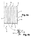
図4aは、図3に示された端部とは逆の、熱伝導性棒状体5の他端部を示している。図4aによれば、インサート2は、電極1とプレート3との間に配置されている。インサート2を形成している波形金属シートの頂部9は、電極1およびプレート3に交互に直接接触している。電極1は、曲げ部8により金属帯状部12に接続された第2舌部7を有している。さらに、プレート3は、曲げ部終端部14により終端されている。終端部14は、有利には、舌部7の方向と平行な方向に延びるように、プレート3に対して直角に配置されている。空隙15が、電極1とプレート3との間の電気的な連続性を遮るために、舌部7を終端部14から分離している。
FIG. 4a shows the other end of the thermally
図4bは、インサート2の構造の詳細図を示しており、インサート2は、金属シートの両端部上において、好ましくはシリコーンまたはポリエステルからなる、絶縁コーティング層19により覆われている。
FIG. 4 b shows a detailed view of the structure of the
図5は、第1の実施形態における加熱モジュールを示している。抵抗要素6は、プレート3が位置決めされた側において、熱伝導性棒状体5に接着されている。プレート3は、加熱モジュール100の内側に位置決めされており、電極1は、加熱モジュール100の外側に位置決めされている。抵抗要素6には、有利には、絶縁要素19が適合され得る。好ましくは、電極1およびプレート3は、それらの端部において湾曲部を有している。抵抗要素6、プレート3、およびインサート2は、電極1の間に配置されている。
FIG. 5 shows the heating module in the first embodiment. The
図6は、第2の実施形態における加熱モジュールを示している。抵抗要素6は、電極1が位置決めされた側において、熱伝導性棒状体5に接着されている。電極1は、モジュール100の内側に位置決めされており、プレート3は、モジュール100の外側に位置決めされている。抵抗要素6には、有利には、絶縁要素が適合され得る。好ましくは、電極1およびプレート3は、それらの端部において湾曲部を有している。抵抗要素6、電極1、およびインサート2は、プレート3の間に配置されている。
FIG. 6 shows a heating module in the second embodiment. The
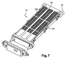
図7に示されるように、補助加熱装置10は、例えば樹脂からなるフレーム18を備えており、フレーム18内に、複数の加熱モジュール100が収容されている。加熱モジュール100は、互いに平行に配置されており、フレーム18を通過するエアに直接さらされるように、フレーム18の全長にわたって延びている。図7に示される非限定的な例では、補助加熱装置10は、3つの加熱モジュール100を備えている。
As shown in FIG. 7, the
図8は、第1の実施形態における加熱モジュールを図示する図5の詳細図を示している。第1の実施形態によれば、プレート3および抵抗要素6は、それぞれ、好ましくはシリコーンまたはポリエステルからなる絶縁コーティング19により覆われている。有利には、絶縁コーティング層19の厚みは、20〜120μmの間である。第1の実施形態によれば、プレート3と抵抗要素6との間の接着は、絶縁コーティング層19を配置する前に実行される。
FIG. 8 shows a detailed view of FIG. 5 illustrating the heating module in the first embodiment. According to the first embodiment, the
図9は、第2の実施形態における加熱モジュールを図示する図6の詳細図を示している。第2の実施形態によれば、電極1、インサート2、プレート3、および抵抗要素6は、それぞれ、好ましくはシリコーンまたはポリエステルからなる絶縁コーティング19により覆われている。有利には、絶縁コーティング層19の厚みは、20〜120μmの間である。第2の実施形態によれば、プレート3と抵抗要素6との間の接着は、絶縁コーティング層19を配置する前に実行される。
FIG. 9 shows a detailed view of FIG. 6 illustrating the heating module in the second embodiment. According to the second embodiment, the
さらに、両方の実施形態によれば、電極1とコネクタ11との間のアセンブリは、また、絶縁層19を配置する前に実行される。接続部11は、しかしながら、絶縁コーティング19により覆われていない。
Furthermore, according to both embodiments, the assembly between the
Claims (7)
前記少なくとも2つの熱伝導性棒状体(5)の各々は、部分的に電気的に絶縁され、
前記少なくとも2つの熱伝導性棒状体(5)の各々は、一方でコネクタ(11)および/または電極(1)と、他方でプレート(3)と、の間に配置された少なくとも1つのインサート(2)により構成され、
前記抵抗器(6)は、前記プレート(3)に直接的に接触して配置され、
前記電極(1)および前記抵抗器(6)は、絶縁コーティング(19)により電気的に絶縁され、
前記インサート(2)、および/または、前記プレート(3)は、絶縁コーティング(19)により電気的に絶縁され、
前記少なくとも2つの熱伝導性棒状体(5)の前記プレート(3)が、前記抵抗器(6)の両側に前記抵抗器(6)に接触して配置されることを特徴とする、エアの流れを加熱することを意図された補助加熱装置(10)の加熱モジュール(100)。 At least two thermally conductive rods (5) separated by an electrical resistor (6) constituted by at least one resistor having a positive temperature coefficient (PTC) , said electrical resistor (6) comprising at least two thermally conductive rods (5) arranged in contact with each other;
Each of the at least two thermally conductive rod-shaped body (5) is partially electrically insulated,
Wherein each of the at least two thermally conductive rod-shaped body (5), on the one hand the connector (11) and / or the electrode (1), at least one insert and the plate (3) on the other hand, arranged between the ( 2),
The resistor (6) is arranged in direct contact with the plate (3),
The electrode (1) and the resistor (6) are electrically insulated by an insulating coating (19),
The insert (2) and / or the plate (3) are electrically insulated by an insulating coating (19) ;
The plate (3) of the at least two thermally conductive rods (5) is arranged on both sides of the resistor (6) in contact with the resistor (6), A heating module (100) of the auxiliary heating device (10) intended to heat the stream.
ことを特徴とする請求項1に記載の加熱モジュール(100)。 The heating module (100) according to claim 1, wherein the electrode (1) is in direct contact with the connector (11).
ことを特徴とする請求項1又は2に記載の加熱モジュール(100)。 The heating module (100) according to claim 1 or 2 , wherein the insert (2), the connector (11) and the electrode (1) are made of aluminum.
ことを特徴とする請求項1乃至3のいずれかに記載の加熱モジュール(100)。 The electrode (1), said insert (2), and / or the resistor (6) is of the claims 1 to 3, characterized by being assembled to each other by conductive adhesive type conductive adhesive material A heating module (100) according to any of the above.
ことを特徴とする請求項1乃至4のいずれかに記載の加熱モジュール(100)。 The heating module (100) according to any of claims 1 to 4 , wherein the insulating coating (19) is made of polyester.
ことを特徴とする請求項5に記載の加熱モジュール(100)。 6. The heating module (100) according to claim 5 , wherein the insulating coating (19) has a thickness of 20 to 120 [mu] m.
Applications Claiming Priority (3)
| Application Number | Priority Date | Filing Date | Title |
|---|---|---|---|
| FR1103148 | 2011-10-14 | ||
| FR1103148A FR2981437B1 (en) | 2011-10-14 | 2011-10-14 | ISOLATED HEATING MODULE FOR ADDITIONAL HEATING DEVICE |
| PCT/EP2012/070139 WO2013053807A1 (en) | 2011-10-14 | 2012-10-11 | Insulated heating module for a supplemental heating device |
Publications (2)
| Publication Number | Publication Date |
|---|---|
| JP2014532159A JP2014532159A (en) | 2014-12-04 |
| JP6301836B2 true JP6301836B2 (en) | 2018-03-28 |
Family
ID=47137674
Family Applications (1)
| Application Number | Title | Priority Date | Filing Date |
|---|---|---|---|
| JP2014535072A Active JP6301836B2 (en) | 2011-10-14 | 2012-10-11 | Insulating heating module for auxiliary heating device |
Country Status (7)
| Country | Link |
|---|---|
| US (1) | US9539881B2 (en) |
| EP (1) | EP2766669B1 (en) |
| JP (1) | JP6301836B2 (en) |
| KR (1) | KR102030200B1 (en) |
| CN (1) | CN103874890A (en) |
| FR (1) | FR2981437B1 (en) |
| WO (1) | WO2013053807A1 (en) |
Families Citing this family (8)
| Publication number | Priority date | Publication date | Assignee | Title |
|---|---|---|---|---|
| DE102013105285B4 (en) | 2013-05-23 | 2022-05-05 | Borgwarner Ludwigsburg Gmbh | Heating device composed of heating modules and heating module therefor |
| USD757917S1 (en) * | 2013-11-27 | 2016-05-31 | Jahwa Electronics Co., Ltd. | Electric heater mounted on air conditioner for vehicle |
| JP2015159085A (en) * | 2014-02-25 | 2015-09-03 | カルソニックカンセイ株式会社 | Temperature adjustment device |
| EP3437905B1 (en) * | 2016-03-30 | 2021-08-18 | Amosense Co., Ltd. | Ptc unit for vehicle heater, ptc heater including same, and air conditioning device for vehicle |
| DE102017121039A1 (en) * | 2017-05-24 | 2018-11-29 | Webasto SE | air heater |
| US20180135883A1 (en) * | 2017-07-11 | 2018-05-17 | Kenneth Stephen Bailey | Advanced water heater utilizing arc-flashpoint technology |
| KR102420478B1 (en) * | 2021-04-20 | 2022-07-13 | (주)엘림 | Car heater using PTC element |
| USD1011493S1 (en) * | 2021-09-03 | 2024-01-16 | Webasto SE | Air heating apparatus |
Family Cites Families (17)
| Publication number | Priority date | Publication date | Assignee | Title |
|---|---|---|---|---|
| CA2002319C (en) * | 1988-11-07 | 1995-04-04 | Yasuaki Matsuda | Positive-temperature-coefficient heating device and process for fabricating the same |
| JPH0810642B2 (en) * | 1988-11-07 | 1996-01-31 | 株式会社亜土電子工業 | PTC thermistor device |
| JPH04101391U (en) * | 1991-02-20 | 1992-09-01 | 株式会社村田製作所 | Positive characteristic thermistor device |
| US5326418A (en) * | 1992-04-14 | 1994-07-05 | Yeh Yuan Chang | Method of making positive-temperature-coefficient thermistor heating element |
| JPH0669002A (en) * | 1992-08-21 | 1994-03-11 | Nippondenso Co Ltd | Positive temperature coefficient characteristic thermistor |
| JPH09213458A (en) * | 1996-02-06 | 1997-08-15 | Denso Corp | Heater unit |
| JPH1116669A (en) * | 1997-06-19 | 1999-01-22 | Kurabe Ind Co Ltd | Heating element |
| FR2855933B1 (en) * | 2003-06-06 | 2006-06-09 | Valeo Climatisation | ELECTRIC HEATING DEVICE, IN PARTICULAR FOR A MOTOR VEHICLE |
| KR100492374B1 (en) | 2005-01-08 | 2005-05-30 | 모딘코리아 유한회사 | PTC rod assembly and Pre-heater including the same |
| EP1839920B1 (en) * | 2006-03-31 | 2013-02-13 | Behr GmbH & Co. KG | Electrical Heater for a vehicle air conditioning system |
| JP4941062B2 (en) * | 2006-09-11 | 2012-05-30 | 株式会社デンソー | Electric heater and vehicle air conditioner |
| KR100836852B1 (en) * | 2006-09-28 | 2008-06-11 | 동우기연 주식회사 | Heater using positive thermister element |
| EP1926347B1 (en) * | 2006-11-23 | 2017-07-05 | Mahle Behr France Rouffach S.A.S | Electric heating device, in particular for a motor vehicle |
| ES2382138T3 (en) * | 2007-07-18 | 2012-06-05 | Eberspächer Catem Gmbh & Co. Kg | Electric heating device |
| JP2009080946A (en) * | 2007-09-25 | 2009-04-16 | Kayu Fu | Heater and manufacturing method therefor |
| KR101030869B1 (en) * | 2008-11-03 | 2011-04-22 | 갑을오토텍(주) | Pulse Width Modulation Control Type High Capacity PTC Heater |
| DE102009040023A1 (en) * | 2009-09-03 | 2011-03-10 | Eichenauer Heizelemente Gmbh & Co. Kg | air heater |
-
2011
- 2011-10-14 FR FR1103148A patent/FR2981437B1/en not_active Expired - Fee Related
-
2012
- 2012-10-11 US US14/349,198 patent/US9539881B2/en active Active
- 2012-10-11 KR KR1020147009581A patent/KR102030200B1/en active IP Right Grant
- 2012-10-11 WO PCT/EP2012/070139 patent/WO2013053807A1/en active Application Filing
- 2012-10-11 JP JP2014535072A patent/JP6301836B2/en active Active
- 2012-10-11 CN CN201280050375.8A patent/CN103874890A/en active Pending
- 2012-10-11 EP EP12781052.1A patent/EP2766669B1/en active Active
Also Published As
| Publication number | Publication date |
|---|---|
| EP2766669B1 (en) | 2018-04-18 |
| KR20140076578A (en) | 2014-06-20 |
| FR2981437B1 (en) | 2018-04-27 |
| EP2766669A1 (en) | 2014-08-20 |
| CN103874890A (en) | 2014-06-18 |
| JP2014532159A (en) | 2014-12-04 |
| FR2981437A1 (en) | 2013-04-19 |
| US20140231411A1 (en) | 2014-08-21 |
| WO2013053807A1 (en) | 2013-04-18 |
| KR102030200B1 (en) | 2019-10-08 |
| US9539881B2 (en) | 2017-01-10 |
Similar Documents
| Publication | Publication Date | Title |
|---|---|---|
| JP6301836B2 (en) | Insulating heating module for auxiliary heating device | |
| JP3794116B2 (en) | Heat exchanger for heating | |
| JP2007046894A (en) | Electric heater module | |
| WO2014010252A1 (en) | Battery heating apparatus | |
| CN108738177B (en) | Electric heating device | |
| US9937772B2 (en) | Heater | |
| JP2008536749A (en) | Electric auxiliary heater for automotive heating or air conditioning | |
| WO2007049746A1 (en) | Heater apparatus | |
| JP2005526223A (en) | Heat exchanger especially for car heating or air conditioning | |
| CN115768638A (en) | Electric fluid heater | |
| KR101030869B1 (en) | Pulse Width Modulation Control Type High Capacity PTC Heater | |
| CN100457489C (en) | Heater with ptc element, particulary for a motor vehicle | |
| US20150300686A1 (en) | Heat sink, associated heating module and corresponding assembly method | |
| US11142115B2 (en) | Light assembly heater systems, apparatus, and methods | |
| WO2012114739A1 (en) | Planar heating element | |
| JPH0253628A (en) | Air heating device | |
| CN110290605B (en) | Heating device | |
| JP6766174B2 (en) | Electrical connection device, heating device, and ventilation, heating and / or air conditioning unit | |
| KR20120140349A (en) | Ptc element connecting device forcar heater | |
| JP2002029249A (en) | Heat exchanger for heating | |
| EP3296660A1 (en) | Electric heater | |
| JP2018515897A (en) | Heating module and electric heating apparatus provided with the heating module | |
| CN113228823A (en) | Heating element with fusing function and heating unit comprising same | |
| JPH10288493A (en) | Heat exchanger for heating | |
| CN215300947U (en) | Car is assisted hot PTC heating monotube, heating element and heater |
Legal Events
| Date | Code | Title | Description |
|---|---|---|---|
| A621 | Written request for application examination |
Free format text: JAPANESE INTERMEDIATE CODE: A621 Effective date: 20150825 |
|
| A131 | Notification of reasons for refusal |
Free format text: JAPANESE INTERMEDIATE CODE: A131 Effective date: 20160624 |
|
| A521 | Request for written amendment filed |
Free format text: JAPANESE INTERMEDIATE CODE: A523 Effective date: 20160908 |
|
| RD03 | Notification of appointment of power of attorney |
Free format text: JAPANESE INTERMEDIATE CODE: A7423 Effective date: 20161213 |
|
| A131 | Notification of reasons for refusal |
Free format text: JAPANESE INTERMEDIATE CODE: A131 Effective date: 20170210 |
|
| A601 | Written request for extension of time |
Free format text: JAPANESE INTERMEDIATE CODE: A601 Effective date: 20170510 |
|
| A521 | Request for written amendment filed |
Free format text: JAPANESE INTERMEDIATE CODE: A523 Effective date: 20170705 |
|
| A02 | Decision of refusal |
Free format text: JAPANESE INTERMEDIATE CODE: A02 Effective date: 20170905 |
|
| A521 | Request for written amendment filed |
Free format text: JAPANESE INTERMEDIATE CODE: A523 Effective date: 20171225 |
|
| A911 | Transfer to examiner for re-examination before appeal (zenchi) |
Free format text: JAPANESE INTERMEDIATE CODE: A911 Effective date: 20180109 |
|
| TRDD | Decision of grant or rejection written | ||
| A01 | Written decision to grant a patent or to grant a registration (utility model) |
Free format text: JAPANESE INTERMEDIATE CODE: A01 Effective date: 20180202 |
|
| A61 | First payment of annual fees (during grant procedure) |
Free format text: JAPANESE INTERMEDIATE CODE: A61 Effective date: 20180301 |
|
| R150 | Certificate of patent or registration of utility model |
Ref document number: 6301836 Country of ref document: JP Free format text: JAPANESE INTERMEDIATE CODE: R150 |
|
| R250 | Receipt of annual fees |
Free format text: JAPANESE INTERMEDIATE CODE: R250 |
|
| R250 | Receipt of annual fees |
Free format text: JAPANESE INTERMEDIATE CODE: R250 |
|
| R250 | Receipt of annual fees |
Free format text: JAPANESE INTERMEDIATE CODE: R250 |
|
| R250 | Receipt of annual fees |
Free format text: JAPANESE INTERMEDIATE CODE: R250 |