JP6301793B2 - DRR image creation method and DRR image creation apparatus - Google Patents
DRR image creation method and DRR image creation apparatus Download PDFInfo
- Publication number
- JP6301793B2 JP6301793B2 JP2014190229A JP2014190229A JP6301793B2 JP 6301793 B2 JP6301793 B2 JP 6301793B2 JP 2014190229 A JP2014190229 A JP 2014190229A JP 2014190229 A JP2014190229 A JP 2014190229A JP 6301793 B2 JP6301793 B2 JP 6301793B2
- Authority
- JP
- Japan
- Prior art keywords
- ray
- drr image
- image creation
- drr
- creation method
- Prior art date
- Legal status (The legal status is an assumption and is not a legal conclusion. Google has not performed a legal analysis and makes no representation as to the accuracy of the status listed.)
- Active
Links
- 238000000034 method Methods 0.000 title claims description 29
- 238000003384 imaging method Methods 0.000 claims description 40
- 238000004364 calculation method Methods 0.000 claims description 35
- 230000005855 radiation Effects 0.000 claims description 31
- 230000000694 effects Effects 0.000 claims description 13
- 238000001228 spectrum Methods 0.000 claims description 7
- 230000001186 cumulative effect Effects 0.000 claims description 5
- 238000002594 fluoroscopy Methods 0.000 description 12
- 238000001959 radiotherapy Methods 0.000 description 12
- 238000010586 diagram Methods 0.000 description 9
- NJPPVKZQTLUDBO-UHFFFAOYSA-N novaluron Chemical compound C1=C(Cl)C(OC(F)(F)C(OC(F)(F)F)F)=CC=C1NC(=O)NC(=O)C1=C(F)C=CC=C1F NJPPVKZQTLUDBO-UHFFFAOYSA-N 0.000 description 6
- 238000002560 therapeutic procedure Methods 0.000 description 6
- 238000013500 data storage Methods 0.000 description 5
- 238000002083 X-ray spectrum Methods 0.000 description 4
- 238000005259 measurement Methods 0.000 description 4
- 238000004088 simulation Methods 0.000 description 4
- 230000010354 integration Effects 0.000 description 3
- 239000003550 marker Substances 0.000 description 3
- 238000009825 accumulation Methods 0.000 description 2
- 238000013170 computed tomography imaging Methods 0.000 description 2
- 238000003702 image correction Methods 0.000 description 2
- 230000001678 irradiating effect Effects 0.000 description 2
- 230000007423 decrease Effects 0.000 description 1
- 238000006073 displacement reaction Methods 0.000 description 1
- 238000010894 electron beam technology Methods 0.000 description 1
- 239000004973 liquid crystal related substance Substances 0.000 description 1
- 238000002601 radiography Methods 0.000 description 1
Images


Description
この発明は、DRR画像作成方法に関し、特に、被検者に対して治療ビームを照射して放射線治療を行うときに、被検者の位置決めを行うため、X線管とX線検出器を備えたX線撮影系により撮影したX線撮影画像との比較に使用されるDRR画像を作成するためのDRR画像作成方法およびDRR画像作成装置に関する。 The present invention relates to a DRR image creation method, and more particularly to an X-ray tube and an X-ray detector for positioning a subject when performing radiation therapy by irradiating the subject with a treatment beam. The present invention relates to a DRR image creation method and a DRR image creation apparatus for creating a DRR image used for comparison with an X-ray image captured by an X-ray imaging system.
X線CT装置により収集した3次元画像データを利用した仮想的透視投影であるDRR(Degital Reconstructed Radiography:デジタル再投影放射線)画像は、例えば、被検者である患者の位置決めに利用される。すなわち、患者に対して治療ビームを照射して放射線治療を行う治療装置においては、DRR画像は、患者の位置決め時に、X線撮影画像の位置ずれを計算するのに使用される。また、患者の位置決め後には、DRR画像とX線撮影画像との位置ずれが許容範囲内にあるかが、医師等による読影により確認される。 A DRR (Digital Reconstructed Radiography) image, which is a virtual perspective projection using three-dimensional image data collected by an X-ray CT apparatus, is used, for example, for positioning a patient who is a subject. That is, in a treatment apparatus that irradiates a patient with a treatment beam and performs radiation treatment, the DRR image is used to calculate the positional deviation of the X-ray image when the patient is positioned. Further, after the patient is positioned, it is confirmed by interpretation by a doctor or the like whether the positional deviation between the DRR image and the X-ray image is within an allowable range.
このDRR画像を作成するときには、コンピュータ上に仮想的に、CT画像を挟んでX線管とX線検出器の幾何学配置であるジオメトリを再現する。そして、仮想的なX線管から仮想的なX線検出器を結ぶ線分上にあるCTデータボクセルにおけるCT値の線積分を求める。そして、CT値の線積分を線減弱係数の線積分に変換してX線の減弱を算出し、これに基づいて各画素に到達する相対X線量を計算する。そして、相対X線量に正規化を施すことにより、各画素の画素値を算出してDRR画像を得ている(特許文献1参照)。 When creating this DRR image, the geometry which is the geometric arrangement of the X-ray tube and the X-ray detector is virtually reproduced on the computer with the CT image interposed therebetween. Then, the line integral of the CT value in the CT data voxel on the line segment connecting the virtual X-ray tube to the virtual X-ray detector is obtained. Then, the X-ray attenuation is calculated by converting the line integral of the CT value into the line integral of the linear attenuation coefficient, and based on this, the relative X-ray dose reaching each pixel is calculated. Then, by normalizing the relative X-ray dose, the pixel value of each pixel is calculated to obtain a DRR image (see Patent Document 1).
DRR画像は、ビームハードニング現象が発生しない単色のX線で、かつ、散乱線の映り込みのない理想的条件下で作成される。一方、実際にX線管とX線検出器を利用したX線撮影においては、ビームハードニング現象や散乱線が発生することから、DRR画像とX線撮影画像とは、画質が異なるものとなる。このような画質の差は、ビームハードニング現象が顕著で、かつ、散乱線が多い脊椎等を撮影する場合等において特に顕著なものとなる。 The DRR image is created under ideal conditions that are monochromatic X-rays that do not cause beam hardening and are not reflected by scattered rays. On the other hand, in X-ray imaging using an X-ray tube and an X-ray detector, a beam hardening phenomenon and scattered radiation occur, so that the DRR image and the X-ray image are different in image quality. . Such a difference in image quality is particularly noticeable when photographing a spine or the like in which the beam hardening phenomenon is remarkable and there are many scattered rays.
DRR画像とX線撮影画像とで画質が異なった場合には、DRR画像とX線撮影画像とを比較して位置ずれを認識することが困難となる。また、医師等が読影によりDRR画像とX線撮影画像との位置ずれが許容範囲内にあるかを判断する場合においても、読影に長い時間を要することとなる。このような場合には、患者に苦痛を与えるだけではなく、高額な放射線治療装置を利用しての放射線治療のスループットが低下するという問題が生ずる。 When the image quality is different between the DRR image and the X-ray image, it is difficult to recognize the displacement by comparing the DRR image and the X-ray image. Further, even when a doctor or the like judges whether the positional deviation between the DRR image and the X-ray image is within an allowable range by interpretation, it takes a long time for interpretation. In such a case, not only does the patient suffer, but there is a problem that the throughput of radiotherapy using an expensive radiotherapy apparatus decreases.
この発明は上記課題を解決するためになされたものであり、X線撮影画像と同等の画質を有するDRR画像を作成することが可能なDRR画像作成方法およびDRR画像作成装置を提供することを目的とする。 The present invention has been made to solve the above-described problem, and an object of the present invention is to provide a DRR image creation method and a DRR image creation apparatus capable of creating a DRR image having an image quality equivalent to that of an X-ray image. And
第1の発明では、放射線治療に用いられるDRR画像を作成するDRR画像作成方法であって、コンピュータ上にX線撮影系の幾何学的配置を再現し、予め収集されたX線CTデータに仮想的に透視投影を行うとともに、前記透視投影に基づいて得られる画素値に対して、ビームハードニング効果に相当する成分を付加する。 In the first invention, a DRR image generation method of generating a DRR image used for ray therapy release, reproduces the geometry of the X-ray imaging system on the computer, previously collected X-ray C T de A perspective projection is virtually performed on the data, and a component corresponding to the beam hardening effect is added to the pixel value obtained based on the perspective projection.
第2の発明では、前記仮想的な透視投影は、前記コンピュータ上に再現したX線撮影系の幾何学的配置におけるX線管と前記X線CTデータの各画素とを結ぶ光線を設定するとともに、この光線上に複数の計算点を設定し、前記計算点のCT値を前記X線管から前記計算点までの累積CT値に基づいて補正し、補正後の各計算点のCT値用いて前記光線上に位置する計算点のCT値を累積し、累積されたCT値に基づいてDRR画像を作成する。 In the second aspect of the invention, the virtual perspective projection, setting a ray connecting the respective pixels of the X-ray CT data and X-ray tube that put the geometry of the X-ray imaging system which reproduces on the computer In addition, a plurality of calculation points are set on the light beam, the CT value of the calculation point is corrected based on the cumulative CT value from the X-ray tube to the calculation point, and the corrected CT value of each calculation point The CT values of the calculation points located on the light beam are accumulated, and a DRR image is created based on the accumulated CT values.
請求項3の発明では、前記透視投影に基づいて得られた各画素値に基づいて、その画素値を補正する。 In the invention of claim 3, the pixel value is corrected based on each pixel value obtained based on the perspective projection.
第4の発明では、前記補正は、予め求められたルックアップテーブルを利用して実行される。 In the fourth invention, the correction is performed using a lookup table obtained in advance.
第5の発明では、X線管から照射されるX線のスペクトルに基づいてルックアップテーブルが選択される。 In the fifth invention, the lookup table is selected based on the spectrum of X- rays emitted from the X- ray tube.
第6の発明では、放射線治療に用いられるDRR画像を作成するDRR画像作成装置であって、コンピュータ上にX線撮影系の幾何学的配置を再現し、予め収集されたX線CTデータに仮想的に透視投影を行うとともに、前記透視投影に基づいて得られる画素値に対して、ビームハードニング効果に相当する成分を付加する画像処理部を備える。 In the sixth invention, a DRR image creation device for creating a DRR image used for ray therapy release, reproduces the geometry of the X-ray imaging system on the computer, previously collected X-ray C T de An image processing unit that virtually performs perspective projection on the data and adds a component corresponding to a beam hardening effect to the pixel value obtained based on the perspective projection.
第7の発明では、放射線治療に用いられるDRR画像を作成するDRR画像作成方法であって、コンピュータ上にX線撮影系の幾何学的配置を再現し、予め収集されたX線CTデータに仮想的に透視投影を行うとともに、前記透視投影に基づいて得られる画素値に対して、前記X線撮影系で発生する散乱線に相当する成分を付加する。 In the seventh invention, a DRR image generation method of generating a DRR image used for ray therapy release, reproduces the geometry of the X-ray imaging system on the computer, previously collected X-ray C T de A perspective projection is virtually performed on the data, and a component corresponding to the scattered radiation generated in the X-ray imaging system is added to the pixel value obtained based on the perspective projection.
第8の発明では、前記透視投影に基づいて得られた各画素値からその画素周辺の散乱線分布を算出し、各画素値にその散乱線分布を加算する。 In the eighth invention, a scattered radiation distribution around the pixel is calculated from each pixel value obtained based on the perspective projection, and the scattered radiation distribution is added to each pixel value.
第9の発明では、前記散乱線分布の算出は、予め求められたルックアップテーブルを利用して実行される。 In the ninth invention, the calculation of the scattered radiation distribution is performed using a lookup table obtained in advance.
第10の発明では、X線管から照射されるX線のスペクトルに基づいてルックアップテーブルが選択される。 In the tenth invention, the lookup table is selected based on the spectrum of X- rays emitted from the X- ray tube.
第11の発明では、放射線治療に用いられるDRR画像を作成するDRR画像作成装置であって、コンピュータ上にX線撮影系の幾何学的配置を再現し、予め収集されたX線CTデータに仮想的に透視投影を行うとともに、前記透視投影に基づいて得られる画素値に対して、前記X線撮影系で発生する散乱線に相当する成分を付加する画像処理部を備えることを特徴とする。 In the eleventh invention, a DRR image creation device for creating a DRR image used for ray therapy release, reproduces the geometry of the X-ray imaging system on the computer, previously collected X-ray C T de An image processing unit that virtually performs perspective projection on the data and adds a component corresponding to scattered radiation generated in the X-ray imaging system to a pixel value obtained based on the perspective projection. Features.
第1および第6の発明によれば、透視投影に基づいて得られる画素値に対してビームハードニング効果に相当する成分を付加することから、X線撮影系により撮影したX線撮影画像と同等の画質を有するDRR画像を作成することが可能となる。このため、DRR画像とX線撮影画像との読影や位置決めを容易に実行することが可能となる。 According to the first and sixth inventions, since a component corresponding to the beam hardening effect is added to the pixel value obtained based on the perspective projection, it is equivalent to the X-ray image captured by the X-ray imaging system. It is possible to create a DRR image having the image quality. For this reason, it is possible to easily execute interpretation and positioning of the DRR image and the X-ray image.
第2の発明によれば、X線CTデータに対してX線撮影時と同等の条件を適用することにより、X線撮影系により撮影したX線撮影画像と同等の画質を有するDRR画像を作成することが可能となる。 According to the second invention, by applying the same conditions as during X-ray imaging to the X-ray C T data, DRR with equivalent image quality and X-ray image taken by the X-ray imaging system An image can be created.
第3の発明によれば、透視投影に基づいて得られた各画素値に基づいてその画素値自身を補正することにより、X線撮影系により撮影したX線撮影画像と同等の画質を有するDRR画像を作成することが可能となる。 According to the third invention, a DRR having an image quality equivalent to that of an X-ray image taken by an X-ray imaging system by correcting the pixel value itself based on each pixel value obtained based on perspective projection. An image can be created.
第4および第5の発明によれば、ルックアップテーブルを利用して適正かつ容易に、画素値を補正することが可能となる。 According to the fourth and fifth aspects, the pixel value can be corrected appropriately and easily using the lookup table.
第7および第11の発明によれば、透視投影に基づいて得られる画素値に対してX線撮影系で発生する散乱線に相当する成分を付加することから、X線撮影系により撮影したX線撮影画像と同等の画質を有するDRR画像を作成することが可能となる。このため、DRR画像とX線撮影画像との読影や位置決めを容易に実行することが可能となる。 According to the seventh and eleventh aspects, a component corresponding to scattered radiation generated in the X-ray imaging system is added to the pixel value obtained based on the perspective projection. It is possible to create a DRR image having an image quality equivalent to that of a line-captured image. For this reason, it is possible to easily execute interpretation and positioning of the DRR image and the X-ray image.
第8の発明によれば、散乱線分布を利用することにより、X線撮影系により撮影したX線撮影画像と同等の画質を有するDRR画像を作成することが可能となる。 According to the eighth aspect, by using the scattered radiation distribution, it is possible to create a DRR image having an image quality equivalent to an X-ray image captured by an X-ray imaging system.
第9および第10の発明によれば、ルックアップテーブルを利用して適正かつ容易に、散乱線分布の算出を行うことが可能となる。 According to the ninth and tenth aspects, it is possible to calculate the scattered radiation distribution appropriately and easily using the lookup table.
以下、この発明の実施の形態を図面に基づいて説明する。図1は、この発明に係るDRR画像の作成方法を適用するX線透視装置をX線治療装置とともに示す概要図である。また、図2は、放射線治療装置におけるヘッド55およびヘッド支持部54の揺動動作を示す説明図である。
Hereinafter, embodiments of the present invention will be described with reference to the drawings. FIG. 1 is a schematic view showing an X-ray fluoroscopic apparatus to which a DRR image creating method according to the present invention is applied together with an X-ray therapy apparatus. FIG. 2 is an explanatory diagram showing the swinging operation of the
放射線治療装置は、テーブル56上で横たわった被検者57の患部に対してX線や電子線等の放射線を照射して放射線治療を行うためのものであり、治療室の床面51上に設置されたガントリー53と、このガントリー53に対して水平方向を向く軸を中心として揺動するヘッド支持部54と、このヘッド支持部54に支持され、被検者57に向けて放射線を照射するためのヘッド55とを備える。ヘッド支持部54の揺動動作により、ヘッド55は、被検者57の患部に対して、様々な角度から放射線を照射することが可能となる。
The radiotherapy apparatus is for performing radiotherapy by irradiating the affected part of the
放射線治療時においては、放射線を患部に正確に照射する必要がある。このため、患部付近には、マーカが設置される。そして、X線透視装置においては、第1X線透視機構と第2X線透視機構とを使用して体内に埋め込まれたマーカを連続的に透視して、第1X線透視機構と第2X線透視機構により得た二次元の透視画像からマーカの三次元の位置情報を演算することで、マーカを高精度で検出する構成となっている。 During radiotherapy, it is necessary to accurately irradiate the affected area with radiation. For this reason, a marker is installed near the affected area. In the X-ray fluoroscopy device, the first X-ray fluoroscopy mechanism and the second X-ray fluoroscopy mechanism are continuously viewed using the first X-ray fluoroscopy mechanism and the second X-ray fluoroscopy mechanism. The marker is detected with high accuracy by calculating the three-dimensional position information of the marker from the two-dimensional perspective image obtained by the above.
このような透視を実行するためのX線透視装置は、第1X線管1aと第1X線検出器2aとから成る第1X線透視機構と、第2X線管1bと第2X線検出器2bとから成る第2X線透視機構と、これらの第1X線管1aと第1X線検出器2aとを互いに対向配置される後述する第1透視位置および第2透視位置に移動させるとともに、第2X線管1bと第2X線検出器2bとを互いに対向配置される第1透視位置および第2透視位置に移動させる移動機構とを備える。なお、第1X線検出器2aおよび第2X線検出器2bとしては、フラットパネルディテクタ(FPD)が使用される。
An X-ray fluoroscope for performing such fluoroscopy includes a first X-ray fluoroscopic mechanism including a first X-ray tube 1a and a
第1X線管1aは、X線管用第1台座3aに支持されている。また、第2X線管1bは、X線管用第2台座3bに支持されている。撮影室の床面51に形成された凹部の底面52には、二つの直線部を円弧部を含む連結部により接続した略U字状のX線管用の第1レール21と、このX線管用の第1レール21と同様二つの直線部を円弧部を含む連結部により接続した略U字状のX線管用の第2レール22とが配設されている。これらのX線管用の第1レール21およびX線管用の第2レール22は、互いに平行に配置されている。そして、X線管用第1台座3aおよびX線管用第2台座3bは、これらのX線管用の第1レール21および第2レール22により案内されて、複数の透視位置に移動する。
The 1st X-ray tube 1a is supported by the
同様に、第1X線検出器2aは、X線検出器用第1台座4aに支持されている。また、第2X線検出器2bは、X線検出器用第2台座4bに支持されている。撮影室の天井からは、二つの直線部を円弧部を含む連結部により接続した略U字状のX線検出器用の第1レール11と、このX線検出器用の第1レール11と同様二つの直線部を円弧部を含む連結部により接続した略U字状のX線検出器用の第2レール12とが吊下されている。これらのX線検出器用の第1レール11およびX線検出器用の第2レール12は、互いに平行に配置されている。そして、X線検出器用第1台座4aおよびX線検出器用第2台座4bは、これらのX線検出器用の第1レール11および第2レール12により案内されて、複数の透視位置に移動する。
Similarly, the
このような放射線治療装置およびX線透視装置においては、被検者57を正しい位置に位置決めして放射線治療を実行するために、X線透視装置で実際に被検者57を撮影したX線撮影画像と、治療計画時に被検者57をCT撮影したデータより得られたDRR画像とを比較する必要がある。このとき、実際にX線管とX線検出器を利用したX線撮影においては、ビームハードニング現象や散乱線が発生することから、DRR画像とX線撮影画像とは、画質が異なるものとなる。このため、この発明においては、ビームハードニング効果や散乱線の影響を考慮して、X線撮影画像と同等の画質を有するDRR画像を作成する画像処理部80を採用している。
In such a radiotherapy apparatus and an X-ray fluoroscopic apparatus, an X-ray imaging in which the subject 57 is actually imaged by the X-ray fluoroscopic apparatus in order to perform the radiotherapy by positioning the subject 57 at the correct position. It is necessary to compare the image with a DRR image obtained from data obtained by CT imaging of the subject 57 at the time of treatment planning. At this time, in X-ray imaging using an X-ray tube and an X-ray detector, a beam hardening phenomenon and scattered radiation occur, so that the DRR image and the X-ray image are different in image quality. Become. For this reason, the present invention employs an
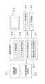
図3は、この発明の第1実施形態に係る画像処理部80を含む制御系を示すブロック図である。
FIG. 3 is a block diagram showing a control system including the
放射線治療装置は、上述したヘッド55、ヘッド支持部54およびガントリー53等を制御する治療装置制御部91を備える。また、X線透視装置は、上述した第1X線管1a、第2X線管1b、第1X線検出器2aおよび第2X線検出器2bや、これらの第1X線管1a、第2X線管1b、第1X線検出器2aおよび第2X線検出器2bを移動させるための移動機構を制御するX線透視装置制御部92を備える。治療装置制御部91とX線透視装置制御部92とは、互いに接続されている。
The radiation therapy apparatus includes a therapy
X線透視装置制御部92は、画像処理部80に接続され、この画像処理部80を介して、液晶表示パネル等から構成される表示部93にX線透視画像を表示する。この画像処理部80は、治療計画時に被検者57をCT撮影して得られたCTデータをCTデータ記憶部94から取得可能となっている。また、この画像処理部80は、後述するDRR画像の作成時に使用されるルックアップテーブルのデータをルックアップテーブル記憶部95から取得可能となっている。なお、このX線透視装置制御部92と画像処理部80とは、論理演算を実行するCPU、装置の制御に必要な動作プログラムが格納されたROM、制御時にデータ等が一時的にストアされるRAM等を備えたコンピュータから構成される。
The X-ray fluoroscopic
この画像処理部80は、機能的構成として、コンピュータ上に再現したX線撮影系の幾何学的配置におけるX線管とX線CTデータの各画素とを結ぶ光線を設定するとともに、この光線上に複数の計算点を設定する計算点設定部81と、計算点設定部81で設定された各計算点のCT値をX線管から計算点までの累積CT値に基づいて補正するCT値補正部82と、CT値補正部82により補正後の各計算点のCT値用いて光線上に位置する計算点のCT値を累積するCT値累積部83と、CT値累積部83により累積されたCT値に基づいてDRR画像を作成するDRR画像作成部84と、を備える。
The
この画像処理部80によりDRR画像を作成するときには、コンピュータ上にX線撮影系の幾何学的配置であるジオメトリを再現し、予め収集されたX線CTデータに仮想的に透視投影を行う。
By this
図4は、仮想的な透視撮影の様子を模式的に示す説明図である。 FIG. 4 is an explanatory diagram schematically showing a state of virtual perspective photographing.
DRR画像作成時には、コンピュータ上に三次元のX線CTデータ100を配置する。そして、コンピュータ上にX線撮影系の幾何学的配置であるジオメトリを再現する。この実施形態においては、X線CTデータ100を挟んで、両側に、図1に示す第1X線管1aまたは第2X線管1bと第1X線検出器2aまたは第2X線検出器2bを配置する。X線CTデータ100は、図3に示すCTデータ記憶部94から取得される。これらのX線CTデータ100および第1X線管1aまたは第2X線管1bと第1X線検出器2aまたは第2X線検出器2bの配置は、図1に示すX線透視装置で透視を実行するときの被検者57と第1X線管1aまたは第2X線管1bと第1X線検出器2aまたは第2X線検出器2bとの配置と同じジオメトリとなっている。ここで、ジオメトリとは、撮影対象とX線管およびX線検出器の幾何学的配置関係を意味する。
At the time of creating a DRR image, three-dimensional
この状態で、画像処理部80における計算点設定部81により、第1X線管1aまたは第2X線管1bと、X線CTデータ100の各画素を介して第1X線検出器2aまたは第2X線検出器2bとを結ぶ多数の光線Lを設定する。なお、図4においては、説明の便宜上、2本の光線L1、L2を図示している。そして、この光線L上に、各々、複数の計算点を設定する。この計算点は、計算点設定部81により、例えば、光線L上に1mm毎に設定される。
In this state, the calculation
次に、計算点設定部81により設定された各計算点のCT値を、線形補間等を行って算出する。そして、このCT値を、CT値補正部82により、各光線Lにおける第1X線管1aまたは第2X線管1bから各計算点までの累積CT値に基づいて補正する。この補正を実行するときには、図3に示すルックアップテーブル記憶部95に記憶されたルックアップテーブルが利用される。このルックアップテーブルは、累積CT値をインデックスとして、CT値を補正する係数を記憶したものである。このルックアップテーブルにおいては、累積CT値が大きいほど、小さな係数となる。
Next, the CT value of each calculation point set by the calculation
ビームハードニング現象は、X線透視に使用されるX線が連続X線であることから、X線が被検者57を通過して減衰するに伴って、X線のスペクトルの高いエネルギー部分が相対的に多くなって、減衰しにくくなる現象である。このため、累積CT値が大きいほど、CT値を補正する係数を小さなものとすると、ビームハードニング効果と同等の補正を行うことが可能となる。このルックアップテーブルは、予め、実測により、あるいは、シミュレーションにより求められる。このルックアップテーブルは、管電圧が異なる場合など、第1X線管1aまたは第2X線管1bから照射されるX線のスペクトルが変化する場合に対応して、ルックアップテーブル記憶部95に複数個が記憶されている。そして、実際に撮影に使用されるX線のスペクトルに基づいて最も適切なルックアップテーブルが選択される。
In the beam hardening phenomenon, since the X-ray used for X-ray fluoroscopy is continuous X-ray, as the X-ray passes through the subject 57 and attenuates, the high energy portion of the X-ray spectrum is increased. This is a phenomenon that becomes relatively large and difficult to attenuate. For this reason, if the coefficient for correcting the CT value is made smaller as the cumulative CT value is larger, correction equivalent to the beam hardening effect can be performed. This lookup table is obtained in advance by actual measurement or simulation. A plurality of lookup tables are stored in the lookup
次に、CT値累積部83により、CT値補正部82により補正された後の光線L上の各計算点のCT値を累積する線積分を実行する。そして、DRR画像作成部84により、累積されたCT値を線減弱係数の線積分に変換してX線の減弱を算出することにより、DRR画像を作成する。
Next, the CT
この実施形態に係る画像処理装置によれば、各光線上に設定した複数の計算点のCT値を第1X線管1aまたは第2X線管1bから各計算点までの累積CT値に基づいて補正し、補正後の各計算点のCT値を用いて各光線上に位置する計算点のCT値を累積することにより、透視投影に基づいて得られる画素値に対して、ビームハードニング効果に相当する成分を付加することができ、X線撮影系により撮影したX線撮影画像と同等の画質を有するDRR画像を作成することが可能となる。 According to the image processing apparatus according to this embodiment, the CT values of a plurality of calculation points set on each ray are corrected based on the accumulated CT values from the first X-ray tube 1a or the second X-ray tube 1b to each calculation point. The CT value of each calculation point located on each ray is accumulated using the corrected CT value of each calculation point, which corresponds to the beam hardening effect for the pixel value obtained based on the perspective projection. Therefore, it is possible to create a DRR image having an image quality equivalent to that of an X-ray image captured by the X-ray imaging system.
次に、この発明の他の実施形態について説明する。図5は、この発明の第2実施形態に係る画像処理部80を含む制御系を示すブロック図である。なお、上述した第1実施形態と同様の部材については、同一の符号を付して詳細な説明を省略する。
Next, another embodiment of the present invention will be described. FIG. 5 is a block diagram showing a control system including an
この画像処理部80は、機能的構成として、コンピュータ上に再現したX線撮影系の幾何学的配置において上述した光線Lを設定し、CT値を累積するCT値累積部83と、CT値累積部83により累積されたCT値に基づいてDRR画像を作成するDRR画像作成部84と、このDRR画像の各画素値に対して、ビームハードニング効果に相当する成分を付加するDRR画像補正部85とを備える。
The
この実施形態においても、図4に示すように、DRR画像作成時には、コンピュータ上に三次元のX線CTデータ100を配置する。そして、コンピュータ上にX線撮影系の幾何学的配置であるジオメトリを再現する。この実施形態においても、X線CTデータ100を挟んで、両側に、図1に示す第1X線管1aまたは第2X線管1bと第1X線検出器2aまたは第2X線検出器2bを配置する。X線CTデータ100は、図3に示すCTデータ記憶部94から取得される。これらのX線CTデータ100および第1X線管1aまたは第2X線管1bと第1X線検出器2aまたは第2X線検出器2bの配置は、図1に示すX線透視装置で透視を実行するときの被検者57と第1X線管1aまたは第2X線管1bと第1X線検出器2aまたは第2X線検出器2bとの配置と同じジオメトリとなっている。
Also in this embodiment, as shown in FIG. 4, three-dimensional
この状態で、第1実施形態の場合と同様に、第1X線管1aまたは第2X線管1bと、X線CTデータ100の各画素を介して第1X線検出器2aまたは第2X線検出器2bとを結ぶ多数の光線Lを設定する。そして、CT値累積部83により、この光線L上のCT値を累積することにより線積分する。しかる後、DRR画像作成部84により、累積されたCT値を線減弱係数の線積分に変換してX線の減弱を算出することにより。DRR画像を作成する。そして、作成されたDRR画像の各画素値に対して、DRR画像補正部85により、ビームハードニング効果に相当する成分を付加する補正を実行する。
In this state, as in the case of the first embodiment, the
より具体的には、DRR画像作成部84により作成されたDRR画像の画素値に対して、これをビームハードニング効果に相当する成分を付加したより大きな画素値に変換する補正を行う。この補正を実行するときには、図5に示すルックアップテーブル記憶部95に記憶されたルックアップテーブルが利用される。このルックアップテーブルは、実測またはシミュレーションにより求められた、DRR画像の画素値とそのときのビームハードニング効果に相当する画素値との関係を記憶したものである。なお、このルックアップテーブルは、管電圧が異なる場合など、第1X線管1aまたは第2X線管1bから照射されるX線のスペクトルが変化する場合に対応して、ルックアップテーブル記憶部95に複数個が記憶されている。そして、実際に撮影に使用されるX線のスペクトルに基づいて最も適切なルックアップテーブルが選択される。
More specifically, the pixel value of the DRR image created by the DRR
この第2実施形態に係る画像処理装置によれば、透視投影に基づいて得られた各画素値に基づいてその画素値を補正することにより、透視投影に基づいて得られる画素値に対して、ビームハードニング効果に相当する成分を付加することができる。このときの補正の精度は、第1実施形態と比較していくらか低いものとはなるが、複雑な計算を実行することなく、高速に、X線撮影系により撮影したX線撮影画像と同等の画質を有するDRR画像を作成することが可能となる。 According to the image processing apparatus according to the second embodiment, by correcting the pixel value based on each pixel value obtained based on the perspective projection, the pixel value obtained based on the perspective projection, A component corresponding to the beam hardening effect can be added. The accuracy of the correction at this time is somewhat lower than that of the first embodiment, but is equivalent to an X-ray image captured by the X-ray imaging system at high speed without executing complicated calculations. It becomes possible to create a DRR image having image quality.
次に、この発明のさらに他の実施形態について説明する。図6は、この発明の第3実施形態に係る画像処理部80を含む制御系を示すブロック図である。なお、上述した第1、第2実施形態と同様の部材については、同一の符号を付して詳細な説明を省略する。
Next, still another embodiment of the present invention will be described. FIG. 6 is a block diagram showing a control system including an
この画像処理部80は、機能的構成として、コンピュータ上に再現したX線撮影系の幾何学的配置において上述した光線Lを設定し、CT値を累積するCT値累積部83と、CT値累積部83により累積されたCT値に基づいてDRR画像を作成するDRR画像作成部84と、DRR画像作成部84により作成されたDRR画像の各画素値からその画素値周辺の散乱線分布を算出する散乱線分布算出部86と、DRR画像作成部84により作成されたDRR画像の各画素値に散乱線分布算出部86により算出された散乱分布を加算する散乱分布加算部87とを備える。
The
この実施形態においても、図4に示すように、DRR画像作成時には、コンピュータ上に三次元のX線CTデータ100を配置する。そして、コンピュータ上にX線撮影系の幾何学的配置であるジオメトリを再現する。この実施形態においても、X線CTデータ100を挟んで、両側に、図1に示す第1X線管1aまたは第2X線管1bと第1X線検出器2aまたは第2X線検出器2bを配置する。X線CTデータ100は、図3に示すCTデータ記憶部94から取得される。これらのX線CTデータ100および第1X線管1aまたは第2X線管1bと第1X線検出器2aまたは第2X線検出器2bの配置は、図1に示すX線透視装置で透視を実行するときの被検者57と第1X線管1aまたは第2X線管1bと第1X線検出器2aまたは第2X線検出器2bとの配置と同じジオメトリとなっている。
Also in this embodiment, as shown in FIG. 4, three-dimensional
この状態で、第1、第2実施形態の場合と同様に、第1X線管1aまたは第2X線管1bと、X線CTデータ100の各画素を介して第1X線検出器2aまたは第2X線検出器2bとを結ぶ多数の光線Lを設定する。そして、CT値累積部83により、この光線L上のCT値を累積することにより線積分する。しかる後、DRR画像作成部84により、累積されたCT値を線減弱係数の線積分に変換してX線の減弱を算出することにより。DRR画像を作成する。そして、作成されたDRR画像の各画素値に対して、X線撮影系で発生する散乱線に相当する成分を付加する。
In this state, as in the first and second embodiments, the
より具体的には、DRR画像作成部84により作成されたDRR画像の各画素に対して、散乱線分布算出部86により、その画素周辺の散乱線分布を求める。この散乱線分布の算出には、図6に示すルックアップテーブル記憶部95に記憶されたルックアップテーブルが利用される。このルックアップテーブルは、実測またはシミュレーションにより求められた、DRR画像の画素値とそのときのその画素周辺の散乱線分布との関係を記憶したものである。この散乱線分布は、点広がり関数として記憶される。そして、この点広がり関数の形状は、上述したように、実測またはシミュレーションにより求められている。なお、このルックアップテーブルは、管電圧が異なる場合など、第1X線管1aまたは第2X線管1bから照射されるX線のスペクトルが変化する場合に対応して、ルックアップテーブル記憶部95に複数個が記憶されている。そして、実際に撮影に使用されるX線のスペクトルに基づいて最も適切なルックアップテーブルが選択される。
More specifically, for each pixel of the DRR image created by the DRR
この第3実施形態に係る画像処理装置によれば、透視投影に基づいて得られた各画素値に基づいてその画素値を補正することにより、透視投影に基づいて得られる画素値に対して、散乱線に相当する成分を付加することができる。このため、X線撮影系により撮影したX線撮影画像と同等の画質を有するDRR画像を作成することが可能となる。 According to the image processing apparatus according to the third embodiment, by correcting the pixel value based on each pixel value obtained based on the perspective projection, the pixel value obtained based on the perspective projection, A component corresponding to scattered radiation can be added. For this reason, it is possible to create a DRR image having an image quality equivalent to that of an X-ray image captured by an X-ray imaging system.
この発明は、例えば、放射線治療等の分野において、DDR画像を作成するときに利用される。 The present invention is used, for example, when creating a DDR image in the field of radiation therapy or the like.
1a 第1X線管
1b 第2X線管
2a 第1X線検出器
2b 第2X線検出器
53 ガントリー
54 ヘッド支持部
55 ヘッド
56 テーブル
57 被検者
80 画像処理部
81 計算点設定部
82 CT値補正部
83 CT値累積部
84 DRR画像作成部
85 DRR画像補正部
86 散乱線分布算出部
87 散乱線分布加算部
91 治療装置制御部
92 X線透視装置制御部
93 表示部
94 CTデータ記憶部
95 ルックアップテーブル記憶部
100 X線CTデータ
DESCRIPTION OF SYMBOLS 1a 1st X-ray tube 1b
Claims (11)
コンピュータ上にX線撮影系の幾何学的配置を再現し、予め収集されたX線CTデータに仮想的に透視投影を行うとともに、前記透視投影に基づいて得られる画素値に対して、ビームハードニング効果に相当する成分を付加することを特徴とするDRR画像作成方法。 A DRR image generation method of generating a DRR image used for radiological treatment,
Reproducing the geometry of the X-ray imaging system on the computer, performs virtually perspective beforehand collected X-ray C T data, the pixel value obtained based on the perspective projection A method of creating a DRR image, comprising adding a component corresponding to a beam hardening effect.
前記仮想的な透視投影は、前記コンピュータ上に再現したX線撮影系の幾何学的配置におけるX線管と前記X線CTデータの各画素とを結ぶ光線を設定するとともに、この光線上に複数の計算点を設定し、
前記計算点のCT値を前記X線管から前記計算点までの累積CT値に基づいて補正し、
補正後の各計算点のCT値を用いて前記光線上に位置する計算点のCT値を累積し、
累積されたCT値に基づいてDRR画像を作成するDRR画像作成方法。 The DRR image creation method according to claim 1,
The virtual perspective projection sets a light beam connecting the respective pixels of the X-ray CT data and X-ray tube that put the geometry of the X-ray imaging system that is reproduced on the computer, on the light Set multiple calculation points in
Correcting the CT value of the calculation point based on the cumulative CT value from the X-ray tube to the calculation point;
Using the CT value of each calculation point after correction, the CT value of the calculation point located on the ray is accumulated,
A DRR image creation method for creating a DRR image based on an accumulated CT value.
前記透視投影に基づいて得られた各画素値に基づいて、その画素値を補正するDRR画像作成方法。 The DRR image creation method according to claim 1,
A DRR image creation method for correcting a pixel value based on each pixel value obtained based on the perspective projection.
前記補正は、予め求められたルックアップテーブルを利用して実行されるDRR画像作成方法。 In the DRR image creation method according to claim 2 or 3,
The correction is a DRR image creation method executed using a lookup table obtained in advance.
X線管から照射されるX線のスペクトルに基づいてルックアップテーブルが選択されるDRR画像作成方法。 The DRR image creation method according to claim 4,
A DRR image creation method in which a lookup table is selected based on a spectrum of X- rays emitted from an X- ray tube.
コンピュータ上にX線撮影系の幾何学的配置を再現し、予め収集されたX線CTデータに仮想的に透視投影を行うとともに、前記透視投影に基づいて得られる画素値に対して、ビームハードニング効果に相当する成分を付加する画像処理部を備えることを特徴とするDRR画像作成装置。 A DRR image creation device for creating a DRR image used for radiological treatment,
Reproducing the geometry of the X-ray imaging system on the computer, performs virtually perspective beforehand collected X-ray C T data, the pixel value obtained based on the perspective projection A DRR image creating apparatus comprising an image processing unit for adding a component corresponding to a beam hardening effect.
コンピュータ上にX線撮影系の幾何学的配置を再現し、予め収集されたX線CTデータに仮想的に透視投影を行うとともに、前記透視投影に基づいて得られる画素値に対して、前記X線撮影系で発生する散乱線に相当する成分を付加することを特徴とするDRR画像作成方法。 A DRR image generation method of generating a DRR image used for radiological treatment,
Reproducing the geometry of the X-ray imaging system on the computer, performs virtually perspective beforehand collected X-ray C T data, the pixel value obtained based on the perspective projection A method of creating a DRR image, wherein a component corresponding to scattered radiation generated in the X-ray imaging system is added.
前記透視投影に基づいて得られた各画素値からその画素周辺の散乱線分布を算出し、各画素値にその散乱線分布を加算するDRR画像作成方法。 The DRR image creation method according to claim 7,
A DRR image creation method of calculating a scattered radiation distribution around a pixel from each pixel value obtained based on the perspective projection and adding the scattered radiation distribution to each pixel value.
前記散乱線分布の算出は、予め求められたルックアップテーブルを利用して実行されるDRR画像作成方法。 The DRR image creation method according to claim 8,
The calculation of the scattered radiation distribution is a DRR image creation method that is executed using a lookup table obtained in advance.
X線管から照射されるX線のスペクトルに基づいてルックアップテーブルが選択されるDRR画像作成方法。 The DRR image creation method according to claim 9,
A DRR image creation method in which a lookup table is selected based on a spectrum of X- rays emitted from an X- ray tube.
コンピュータ上にX線撮影系の幾何学的配置を再現し、予め収集されたX線CTデータに仮想的に透視投影を行うとともに、前記透視投影に基づいて得られる画素値に対して、前記X線撮影系で発生する散乱線に相当する成分を付加する画像処理部を備えることを特徴とするDRR画像作成装置。 A DRR image creation device for creating a DRR image used for radiological treatment,
Reproducing the geometry of the X-ray imaging system on the computer, performs virtually perspective beforehand collected X-ray C T data, the pixel value obtained based on the perspective projection A DRR image creating apparatus comprising: an image processing unit for adding a component corresponding to scattered radiation generated in the X-ray imaging system.
Priority Applications (1)
| Application Number | Priority Date | Filing Date | Title |
|---|---|---|---|
| JP2014190229A JP6301793B2 (en) | 2014-09-18 | 2014-09-18 | DRR image creation method and DRR image creation apparatus |
Applications Claiming Priority (1)
| Application Number | Priority Date | Filing Date | Title |
|---|---|---|---|
| JP2014190229A JP6301793B2 (en) | 2014-09-18 | 2014-09-18 | DRR image creation method and DRR image creation apparatus |
Publications (3)
| Publication Number | Publication Date |
|---|---|
| JP2016059612A JP2016059612A (en) | 2016-04-25 |
| JP2016059612A5 JP2016059612A5 (en) | 2017-07-13 |
| JP6301793B2 true JP6301793B2 (en) | 2018-03-28 |
Family
ID=55796493
Family Applications (1)
| Application Number | Title | Priority Date | Filing Date |
|---|---|---|---|
| JP2014190229A Active JP6301793B2 (en) | 2014-09-18 | 2014-09-18 | DRR image creation method and DRR image creation apparatus |
Country Status (1)
| Country | Link |
|---|---|
| JP (1) | JP6301793B2 (en) |
Families Citing this family (5)
| Publication number | Priority date | Publication date | Assignee | Title |
|---|---|---|---|---|
| JP2018068584A (en) * | 2016-10-28 | 2018-05-10 | 株式会社島津製作所 | X-ray fluoroscope |
| JP6883800B2 (en) * | 2016-11-15 | 2021-06-09 | 株式会社島津製作所 | DRR image creation device |
| US10186055B2 (en) | 2017-03-23 | 2019-01-22 | Shimadzu Corporation | DRR image generation method and DRR image generation apparatus |
| WO2019012686A1 (en) * | 2017-07-14 | 2019-01-17 | 株式会社日立製作所 | Particle beam treatment device and drr image creation method |
| US11839501B2 (en) * | 2018-01-09 | 2023-12-12 | Shimadzu Corporation | Image creation device |
Family Cites Families (4)
| Publication number | Priority date | Publication date | Assignee | Title |
|---|---|---|---|---|
| JP3896188B2 (en) * | 1997-06-13 | 2007-03-22 | 株式会社日立製作所 | Image processing device for radiation therapy planning |
| US7756567B2 (en) * | 2003-08-29 | 2010-07-13 | Accuray Incorporated | Image guided radiosurgery method and apparatus using registration of 2D radiographic images with digitally reconstructed radiographs of 3D scan data |
| JP5329256B2 (en) * | 2009-02-19 | 2013-10-30 | 株式会社日立製作所 | Bed positioning system, radiation therapy system, and bed positioning method |
| JP5279637B2 (en) * | 2009-07-02 | 2013-09-04 | 株式会社日立製作所 | Bed positioning system and bed positioning method |
-
2014
- 2014-09-18 JP JP2014190229A patent/JP6301793B2/en active Active
Also Published As
| Publication number | Publication date |
|---|---|
| JP2016059612A (en) | 2016-04-25 |
Similar Documents
| Publication | Publication Date | Title |
|---|---|---|
| JP6265276B2 (en) | X-ray fluoroscopic apparatus, moving body tracking apparatus for radiotherapy, and X-ray detector | |
| JP6301793B2 (en) | DRR image creation method and DRR image creation apparatus | |
| JP6636923B2 (en) | X-ray imaging device | |
| JP2016059612A5 (en) | ||
| US20130148779A1 (en) | Radiation tomography apparatus | |
| JP6215108B2 (en) | Bed positioning device for radiation therapy equipment | |
| JP5437001B2 (en) | Radiography equipment | |
| US20130178690A1 (en) | Radiotherapy apparatus controller and radiotherapy apparatus control method | |
| WO2012026160A1 (en) | Control device for radiation therapy device and control method for radiation therapy device | |
| US9420985B2 (en) | X-ray diagnostic apparatus and dose distribution generation method | |
| US8976928B2 (en) | Radiographic apparatus and image acquiring method | |
| JP2017035204A (en) | Image processing method and fluoroscopic apparatus | |
| JP2017189526A (en) | Information processing device and radiotherapy system | |
| JP6607015B2 (en) | X-ray imaging apparatus, subject positioning apparatus, and subject positioning method | |
| JP6394082B2 (en) | X-ray inspection equipment | |
| JP2015195970A (en) | X-ray diagnostic apparatus | |
| WO2011058612A1 (en) | Radiation image taking device | |
| JP2018153277A (en) | Fluoroscopic apparatus | |
| JP5279637B2 (en) | Bed positioning system and bed positioning method | |
| JP5584037B2 (en) | Radiation imaging apparatus, control method therefor, and program | |
| JP5238296B2 (en) | X-ray apparatus and rotational imaging method | |
| US20150374326A1 (en) | X-ray diagnostic apparatus | |
| JP6883800B2 (en) | DRR image creation device | |
| TWI645836B (en) | Particle beam therapy apparatus and digital reconstructed radiography image creation method | |
| CN107809954B (en) | Display of depth position of computer tomography slice image relative to object to be imaged |
Legal Events
| Date | Code | Title | Description |
|---|---|---|---|
| A521 | Request for written amendment filed |
Free format text: JAPANESE INTERMEDIATE CODE: A523 Effective date: 20170530 |
|
| A621 | Written request for application examination |
Free format text: JAPANESE INTERMEDIATE CODE: A621 Effective date: 20170530 |
|
| A521 | Request for written amendment filed |
Free format text: JAPANESE INTERMEDIATE CODE: A821 Effective date: 20170530 |
|
| TRDD | Decision of grant or rejection written | ||
| A01 | Written decision to grant a patent or to grant a registration (utility model) |
Free format text: JAPANESE INTERMEDIATE CODE: A01 Effective date: 20180213 |
|
| A61 | First payment of annual fees (during grant procedure) |
Free format text: JAPANESE INTERMEDIATE CODE: A61 Effective date: 20180301 |
|
| R150 | Certificate of patent or registration of utility model |
Ref document number: 6301793 Country of ref document: JP Free format text: JAPANESE INTERMEDIATE CODE: R150 |
|
| R250 | Receipt of annual fees |
Free format text: JAPANESE INTERMEDIATE CODE: R250 |
|
| R250 | Receipt of annual fees |
Free format text: JAPANESE INTERMEDIATE CODE: R250 |
|
| R250 | Receipt of annual fees |
Free format text: JAPANESE INTERMEDIATE CODE: R250 |
|
| R250 | Receipt of annual fees |
Free format text: JAPANESE INTERMEDIATE CODE: R250 |