JP6301368B2 - Apparatus and method for generating a frequency enhancement signal using enhancement signal shaping - Google Patents
Apparatus and method for generating a frequency enhancement signal using enhancement signal shaping Download PDFInfo
- Publication number
- JP6301368B2 JP6301368B2 JP2015555673A JP2015555673A JP6301368B2 JP 6301368 B2 JP6301368 B2 JP 6301368B2 JP 2015555673 A JP2015555673 A JP 2015555673A JP 2015555673 A JP2015555673 A JP 2015555673A JP 6301368 B2 JP6301368 B2 JP 6301368B2
- Authority
- JP
- Japan
- Prior art keywords
- frequency
- signal
- core
- energy
- enhancement
- Prior art date
- Legal status (The legal status is an assumption and is not a legal conclusion. Google has not performed a legal analysis and makes no representation as to the accuracy of the status listed.)
- Active
Links
- 238000000034 method Methods 0.000 title claims description 75
- 238000007493 shaping process Methods 0.000 title claims description 39
- 238000009499 grossing Methods 0.000 claims description 68
- 230000003595 spectral effect Effects 0.000 claims description 55
- 230000002123 temporal effect Effects 0.000 claims description 21
- 238000004590 computer program Methods 0.000 claims description 13
- 230000007423 decrease Effects 0.000 claims description 13
- 238000012545 processing Methods 0.000 claims description 11
- 238000001228 spectrum Methods 0.000 claims description 9
- 230000001419 dependent effect Effects 0.000 claims description 7
- 230000009467 reduction Effects 0.000 claims description 7
- 230000005236 sound signal Effects 0.000 claims description 5
- 230000002708 enhancing effect Effects 0.000 claims 1
- 230000015572 biosynthetic process Effects 0.000 description 14
- 238000003786 synthesis reaction Methods 0.000 description 14
- 230000006870 function Effects 0.000 description 11
- 238000012937 correction Methods 0.000 description 8
- 238000013459 approach Methods 0.000 description 7
- 230000008569 process Effects 0.000 description 6
- 230000005540 biological transmission Effects 0.000 description 5
- 238000004458 analytical method Methods 0.000 description 4
- 238000004891 communication Methods 0.000 description 4
- 230000007274 generation of a signal involved in cell-cell signaling Effects 0.000 description 4
- 238000013213 extrapolation Methods 0.000 description 3
- 238000005070 sampling Methods 0.000 description 3
- 230000008901 benefit Effects 0.000 description 2
- 238000004364 calculation method Methods 0.000 description 2
- 230000008859 change Effects 0.000 description 2
- 238000006243 chemical reaction Methods 0.000 description 2
- 238000001914 filtration Methods 0.000 description 2
- 238000003780 insertion Methods 0.000 description 2
- 230000037431 insertion Effects 0.000 description 2
- 230000006978 adaptation Effects 0.000 description 1
- 230000003416 augmentation Effects 0.000 description 1
- 230000015556 catabolic process Effects 0.000 description 1
- 230000008878 coupling Effects 0.000 description 1
- 238000010168 coupling process Methods 0.000 description 1
- 238000005859 coupling reaction Methods 0.000 description 1
- 238000006731 degradation reaction Methods 0.000 description 1
- 238000001514 detection method Methods 0.000 description 1
- 238000010586 diagram Methods 0.000 description 1
- 238000005516 engineering process Methods 0.000 description 1
- 238000011156 evaluation Methods 0.000 description 1
- 230000005284 excitation Effects 0.000 description 1
- 230000006872 improvement Effects 0.000 description 1
- 230000007774 longterm Effects 0.000 description 1
- 238000012986 modification Methods 0.000 description 1
- 230000004048 modification Effects 0.000 description 1
- 238000004321 preservation Methods 0.000 description 1
- 238000013139 quantization Methods 0.000 description 1
- 230000010076 replication Effects 0.000 description 1
- 230000000630 rising effect Effects 0.000 description 1
- 230000009466 transformation Effects 0.000 description 1
- 230000007704 transition Effects 0.000 description 1
Images


Classifications
-
- G—PHYSICS
- G10—MUSICAL INSTRUMENTS; ACOUSTICS
- G10L—SPEECH ANALYSIS OR SYNTHESIS; SPEECH RECOGNITION; SPEECH OR VOICE PROCESSING; SPEECH OR AUDIO CODING OR DECODING
- G10L19/00—Speech or audio signals analysis-synthesis techniques for redundancy reduction, e.g. in vocoders; Coding or decoding of speech or audio signals, using source filter models or psychoacoustic analysis
- G10L19/04—Speech or audio signals analysis-synthesis techniques for redundancy reduction, e.g. in vocoders; Coding or decoding of speech or audio signals, using source filter models or psychoacoustic analysis using predictive techniques
- G10L19/08—Determination or coding of the excitation function; Determination or coding of the long-term prediction parameters
- G10L19/12—Determination or coding of the excitation function; Determination or coding of the long-term prediction parameters the excitation function being a code excitation, e.g. in code excited linear prediction [CELP] vocoders
-
- G—PHYSICS
- G10—MUSICAL INSTRUMENTS; ACOUSTICS
- G10L—SPEECH ANALYSIS OR SYNTHESIS; SPEECH RECOGNITION; SPEECH OR VOICE PROCESSING; SPEECH OR AUDIO CODING OR DECODING
- G10L21/00—Processing of the speech or voice signal to produce another audible or non-audible signal, e.g. visual or tactile, in order to modify its quality or its intelligibility
- G10L21/02—Speech enhancement, e.g. noise reduction or echo cancellation
- G10L21/038—Speech enhancement, e.g. noise reduction or echo cancellation using band spreading techniques
-
- G—PHYSICS
- G10—MUSICAL INSTRUMENTS; ACOUSTICS
- G10L—SPEECH ANALYSIS OR SYNTHESIS; SPEECH RECOGNITION; SPEECH OR VOICE PROCESSING; SPEECH OR AUDIO CODING OR DECODING
- G10L19/00—Speech or audio signals analysis-synthesis techniques for redundancy reduction, e.g. in vocoders; Coding or decoding of speech or audio signals, using source filter models or psychoacoustic analysis
- G10L19/02—Speech or audio signals analysis-synthesis techniques for redundancy reduction, e.g. in vocoders; Coding or decoding of speech or audio signals, using source filter models or psychoacoustic analysis using spectral analysis, e.g. transform vocoders or subband vocoders
- G10L19/0204—Speech or audio signals analysis-synthesis techniques for redundancy reduction, e.g. in vocoders; Coding or decoding of speech or audio signals, using source filter models or psychoacoustic analysis using spectral analysis, e.g. transform vocoders or subband vocoders using subband decomposition
-
- G—PHYSICS
- G10—MUSICAL INSTRUMENTS; ACOUSTICS
- G10L—SPEECH ANALYSIS OR SYNTHESIS; SPEECH RECOGNITION; SPEECH OR VOICE PROCESSING; SPEECH OR AUDIO CODING OR DECODING
- G10L19/00—Speech or audio signals analysis-synthesis techniques for redundancy reduction, e.g. in vocoders; Coding or decoding of speech or audio signals, using source filter models or psychoacoustic analysis
- G10L19/02—Speech or audio signals analysis-synthesis techniques for redundancy reduction, e.g. in vocoders; Coding or decoding of speech or audio signals, using source filter models or psychoacoustic analysis using spectral analysis, e.g. transform vocoders or subband vocoders
- G10L19/032—Quantisation or dequantisation of spectral components
-
- G—PHYSICS
- G10—MUSICAL INSTRUMENTS; ACOUSTICS
- G10L—SPEECH ANALYSIS OR SYNTHESIS; SPEECH RECOGNITION; SPEECH OR VOICE PROCESSING; SPEECH OR AUDIO CODING OR DECODING
- G10L19/00—Speech or audio signals analysis-synthesis techniques for redundancy reduction, e.g. in vocoders; Coding or decoding of speech or audio signals, using source filter models or psychoacoustic analysis
- G10L19/04—Speech or audio signals analysis-synthesis techniques for redundancy reduction, e.g. in vocoders; Coding or decoding of speech or audio signals, using source filter models or psychoacoustic analysis using predictive techniques
- G10L19/06—Determination or coding of the spectral characteristics, e.g. of the short-term prediction coefficients
-
- G—PHYSICS
- G10—MUSICAL INSTRUMENTS; ACOUSTICS
- G10L—SPEECH ANALYSIS OR SYNTHESIS; SPEECH RECOGNITION; SPEECH OR VOICE PROCESSING; SPEECH OR AUDIO CODING OR DECODING
- G10L25/00—Speech or voice analysis techniques not restricted to a single one of groups G10L15/00 - G10L21/00
- G10L25/03—Speech or voice analysis techniques not restricted to a single one of groups G10L15/00 - G10L21/00 characterised by the type of extracted parameters
- G10L25/18—Speech or voice analysis techniques not restricted to a single one of groups G10L15/00 - G10L21/00 characterised by the type of extracted parameters the extracted parameters being spectral information of each sub-band
-
- G—PHYSICS
- G10—MUSICAL INSTRUMENTS; ACOUSTICS
- G10L—SPEECH ANALYSIS OR SYNTHESIS; SPEECH RECOGNITION; SPEECH OR VOICE PROCESSING; SPEECH OR AUDIO CODING OR DECODING
- G10L19/00—Speech or audio signals analysis-synthesis techniques for redundancy reduction, e.g. in vocoders; Coding or decoding of speech or audio signals, using source filter models or psychoacoustic analysis
- G10L2019/0001—Codebooks
- G10L2019/0012—Smoothing of parameters of the decoder interpolation
-
- G—PHYSICS
- G10—MUSICAL INSTRUMENTS; ACOUSTICS
- G10L—SPEECH ANALYSIS OR SYNTHESIS; SPEECH RECOGNITION; SPEECH OR VOICE PROCESSING; SPEECH OR AUDIO CODING OR DECODING
- G10L19/00—Speech or audio signals analysis-synthesis techniques for redundancy reduction, e.g. in vocoders; Coding or decoding of speech or audio signals, using source filter models or psychoacoustic analysis
- G10L2019/0001—Codebooks
- G10L2019/0016—Codebook for LPC parameters
-
- G—PHYSICS
- G10—MUSICAL INSTRUMENTS; ACOUSTICS
- G10L—SPEECH ANALYSIS OR SYNTHESIS; SPEECH RECOGNITION; SPEECH OR VOICE PROCESSING; SPEECH OR AUDIO CODING OR DECODING
- G10L21/00—Processing of the speech or voice signal to produce another audible or non-audible signal, e.g. visual or tactile, in order to modify its quality or its intelligibility
- G10L21/02—Speech enhancement, e.g. noise reduction or echo cancellation
- G10L21/038—Speech enhancement, e.g. noise reduction or echo cancellation using band spreading techniques
- G10L21/0388—Details of processing therefor
Description
本発明は、オーディオ符号化に基づき、特にバンド幅拡張、スペクトルバンド複製または知的ギャップ充填のような周波数増強プロシージャに基づく。 The invention is based on audio coding, in particular on frequency enhancement procedures such as bandwidth extension, spectral band replication or intelligent gap filling.
本発明は、特に非ガイド式の、すなわちデコーダ側がサイド情報なしにまたは最小限のサイド情報のみで動作する、周波数増強プロシージャに関する。 The invention relates in particular to a frequency enhancement procedure that is non-guided, i.e. the decoder side operates without side information or with minimal side information.
知覚的なオーディコーデックは、特に(相対的に)低ビットレートで動作するとき、しばしば音声信号の全知覚可能周波数レンジのローパス部分のみを量子化し、符号化する。
このアプローチは、符号化された低周波信号に対する許容可能な品質を保証するが、多くのリスナーはハイパス部分の欠落を品質劣化として知覚する。この問題を克服するために、欠落する高周波部分を、バンド幅拡張スキームによって合成することができる。
Perceptual audio codecs often quantize and encode only the low-pass portion of the entire perceivable frequency range of the speech signal, especially when operating at (relatively) low bit rates.
This approach guarantees acceptable quality for the encoded low frequency signal, but many listeners perceive missing high-pass portions as quality degradation. In order to overcome this problem, the missing high frequency part can be synthesized by a bandwidth extension scheme.
技術水準のコーデックは、低周波信号を符号化するために、AACのような波形保存コーダ、またはスピーチコーダのようなパラメトリックコーダをしばしば用いる。これらのコーダは、特定のストップ周波数まで動作する。この周波数は、クロスオーバー周波数と呼ばれる。クロスオーバー周波数の下の周波数部分は、ローバンドと呼ばれる。バンド幅拡張スキームによって合成されるクロスオーバー周波数より上の信号は、ハイバンドと呼ばれる。 State-of-the-art codecs often use a waveform storage coder such as AAC or a parametric coder such as a speech coder to encode low frequency signals. These coders operate up to a specific stop frequency. This frequency is called the crossover frequency. The frequency portion below the crossover frequency is called the low band. Signals above the crossover frequency synthesized by the bandwidth extension scheme are called highband.
バンド幅拡張は、通常は伝送された信号(ローバンド)と追加のサイド情報によって欠落バンド幅(ハイバンド)を合成する。低ビットレートのオーディオ符号化の分野で適用される場合、追加の情報ができる限り起こりうる追加のビットレートを消費しないようにすべきである。従って、追加の情報に対して、通常はパラメトリック表現が選択される。このパラメトリック表現は、エンコーダから比較的低いビットレートで伝送される(ガイド式のバンド幅拡張)か、デコーダにおいて特定の信号特性に基づいて推定される(非ガイド式のバンド幅拡張)。後者のケースにおいて、パラメータは全くビットレートを消費しない。 Bandwidth expansion usually combines the missing bandwidth (high band) with the transmitted signal (low band) and additional side information. When applied in the field of low bit rate audio coding, additional information should not consume as much additional bit rate as possible. Therefore, a parametric representation is usually selected for additional information. This parametric representation is transmitted from the encoder at a relatively low bit rate (guided bandwidth extension) or estimated at the decoder based on specific signal characteristics (non-guided bandwidth extension). In the latter case, the parameter does not consume any bit rate.
ハイバンドの合成は、通常は次の2つのパートからなる。
1.高周波コンテンツの生成
これは、低周波コンテンツ(の一部)をハイバンドにコピーまたは反転させる、またはホワイトノイズまたは整形されたノイズまたは他の人工信号部分をハイバンドに挿入することによってなすことができる。
2.パラメトリック情報に従って生成された高周波コンテンツの調整
これは、パラメトリック表現による形状、調性/ノイジネスおよびエネルギーの操作を含む。
High band synthesis usually consists of the following two parts.
1. Generation of high frequency content This can be done by copying or inverting (part of) low frequency content to the high band, or inserting white noise or shaped noise or other artificial signal parts into the high band. .
2. Adjustment of high-frequency content generated according to parametric information This includes manipulation of shape, tonality / noisiness and energy with parametric representation.
合成プロセスのゴールは、通常は知覚的にオリジナル信号に近い信号を達成することである。このゴールにマッチすることができない場合、合成された部分はリスナーに対して最も妨害しないものとすべきである。 The goal of the synthesis process is to achieve a signal that is usually perceptually close to the original signal. If this goal cannot be matched, the synthesized part should be least disturbing to the listener.
ガイド式のBWEスキーム以外の、非ガイド式のバンド幅拡張は、ハイバンドの合成に対して追加の情報に依存することができない。その代わりに、通常はローバンドとハイバンドの間の相関を実施する経験則を用いる。多くの音楽ピースや声に出したスピーチセグメントは高低の周波数バンド間で高い相関を呈するが、これは、通常は無声音のまたは摩擦音のスピーチセグメントに対するケースでない。摩擦音のサウンドは、特定の周波数より上に高いエネルギーを持つが、低周波数レンジにおいて極めて少ないエネルギーを持つ。この周波数がクロスオーバー周波数の近くにある場合、ローバンドは関連する信号部分をほとんど含まないので、クロスオーバー周波数より上に人工信号を生成することは問題がある可能性がある。この課題に対処するために、この種のサウンドの良好な検出が有用である。 Non-guided bandwidth extensions other than the guided BWE scheme cannot rely on additional information for high-band synthesis. Instead, a rule of thumb is usually used to perform the correlation between the low and high bands. Many musical pieces and voiced speech segments exhibit a high correlation between high and low frequency bands, but this is not usually the case for unvoiced or frictional speech segments. Frictional sounds have high energy above a certain frequency, but very little energy in the low frequency range. If this frequency is near the crossover frequency, it can be problematic to generate an artificial signal above the crossover frequency, since the low band contains little associated signal portion. To address this challenge, good detection of this type of sound is useful.
HE-AACは、ローバンドに対して波形保存コーデック(AAC)およびハイバンドに対してパラメトリックコーデック(SBR)からなる周知のコーデックである。デコーダ側において、ハイバンド信号は、QMFフィルタバンクを用いて復号化されたAAC信号を周波数ドメインに変換することによって生成される。引き続いて、ローバンド信号のサブバンドはハイバンドへコピーされる(高周波コンテンツの生成)。このハイバンド信号は、次に、伝送されたパラメトリックサイド情報に基づいて、スペクトル包絡、調性および暗騒音において調整される(生成された高周波コンテンツの調整)。この方法は、ガイド式のBWEアプローチを用いるので、ハイバンドとローバンドの間の弱い相関は一般に問題とならず、適当なパラメータセットを伝送することによって克服することができる。しかしながら、これは付加的なビットレートを必要とし、それは一定のアプリケーションシナリオに対して受け入れられないかもしれない。 HE-AAC is a well-known codec consisting of a waveform preservation codec (AAC) for the low band and a parametric codec (SBR) for the high band. On the decoder side, the high band signal is generated by converting the AAC signal decoded using the QMF filter bank into the frequency domain. Subsequently, the subbands of the lowband signal are copied to the highband (generation of high frequency content). This high band signal is then adjusted in spectral envelope, tonality and background noise (adjustment of the generated high frequency content) based on the transmitted parametric side information. Since this method uses a guided BWE approach, the weak correlation between high band and low band is generally not a problem and can be overcome by transmitting the appropriate parameter set. However, this requires an additional bit rate, which may not be acceptable for certain application scenarios.
ITU標準G.722.2 は、時間ドメインにおいてのみ動作する、すなわち周波数ドメインにおいていかなる演算も実行しない、スピーチコーデックである。この種のデコーダは、12.8kHzのサンプリングレートで時間ドメイン信号を出力し、引き続いて16kHzまでアップサンプリングされる。高周波コンテンツ(6.4−7.0kHz)の生成は、バンドパスノイズの挿入に基づいている。多くの演算モードにおいて、ノイズのスペクトル整形はいかなるサイド情報も用いることなくなされ、ノイズエネルギーに関して最も高いビットレート情報を有する演算モードにおいてのみ、ビットストリームにおいて伝送される。簡潔のため、そして全てのアプリケーションシナリオが追加のパラメータセットの伝送をもたらすわけではないので、以下において、いかなるサイド情報も用いることのないハイバンド信号の生成のみが記載される。 ITU standard G.722.2 is a speech codec that operates only in the time domain, ie does not perform any operations in the frequency domain. This type of decoder outputs a time domain signal at a sampling rate of 12.8 kHz and is subsequently upsampled to 16 kHz. The generation of high frequency content (6.4-7.0 kHz) is based on the insertion of bandpass noise. In many computation modes, noise spectral shaping is done without using any side information and is transmitted in the bitstream only in the computation mode with the highest bit rate information with respect to noise energy. For the sake of brevity and not all application scenarios result in the transmission of an additional parameter set, only the generation of high-band signals without using any side information will be described below.
ハイバンド信号の生成に対して、ノイズ信号は、コアの励起信号と同じエネルギーを持つようにスケーリングされる。信号の無声音部分により多くのエネルギーを与えるために、スペクトル傾斜eが計算される。

ここで、sは、400Hzのカットオフ周波数を有するハイパスフィルタリングされた復号化コア信号である。nは、サンプルインデックスである。高周波においてより少ないエネルギーが存在する有声音セグメントのケースにおいてeは1に近づくが、無声音セグメントに対してeはゼロに近づく。ハイバンド信号においてより多くのエネルギーを持つために、無声音のスピーチに対して、ノイズのエネルギーに(1−e)が掛けられる。最後に、スケーリングされたノイズ信号は、ラインスペクトル周波数(LSF)ドメインにおける外挿によってコア線形予測符号化(LPC)フィルタから導き出されるフィルタによってフィルタリングされる。 Here, s is a high-pass filtered decoded core signal having a cutoff frequency of 400 Hz. n is a sample index. In the case of voiced sound segments where there is less energy at high frequencies, e approaches 1 but for unvoiced sound segments e approaches zero. In order to have more energy in the high band signal, the noise energy is multiplied by (1-e) for unvoiced speech. Finally, the scaled noise signal is filtered by a filter derived from the core linear predictive coding (LPC) filter by extrapolation in the line spectral frequency (LSF) domain.
完全に時間ドメインで動作するG.722.2 の非ガイド式のバンド幅拡張には、以下の欠点を有する。
1.生成されたHFコンテンツはノイズに基づいている。これは、HF信号が音のハーモニック低周波信号(例えば音楽)と結合される場合に、聞き取れるアーチファクトを創生する。この種のアーチファクトを回避するため、G.722.2 は、生成されたHF信号のエネルギーを強く制限し、それはまたバンド幅拡張の潜在的利益を制限する。従って、残念なことに、サウンドのブライトネスの最大の可能な改善またはスピーチ信号の明瞭度における最大の獲得できる増加も制限される。
2.この非ガイド式のバンド幅拡張は時間ドメインにおいて動作するので、フィルタ演算は付加的なアルゴリズム的遅延を生ずる。この付加的な遅延は、双方向通信シナリオにおけるユーザ経験の品質を下げるか、または所定の通信技術標準の必要条件の項目によって許容されないかもしれない。
3.また、信号処理は時間ドメインにおいて実行されるので、フィルタ演算は不安定の傾向がある。さらに、時間ドメインフィルタは高い計算量を有する。
4.ハイバンド信号のエネルギーのオーバーオール合計のみがコア信号のエネルギーに適応される(そして、更にスペクトル傾斜によって重み付けされる)ので、コア信号の上側周波数レンジ(ちょうどクロスオーバー周波数の下の信号)とハイバンド信号の間のクロスオーバー周波数におけるエネルギーの有意なローカルミスマッチがあるかもしれない。例えば、これは、特に超低周波数レンジにおけるエネルギー集中を呈するが、上側周波数レンジにおいてほとんどエネルギーを含まない音の信号に対するケースになる。
5.さらにまた、時間ドメイン表現においてスペクトル勾配を推定することは演算的に複雑である。周波数ドメインにおいて、スペクトル勾配の外挿は非常に効率的になすことができる。例えば摩擦音の大部分のエネルギーは高い周波数レンジに集中しているので、これらは、保守的なエネルギーとG.722.2 におけるようなスペクトル勾配の推定戦略が適用される場合、鈍く聞こえるかもしれない(1.を参照)。
The non-guided bandwidth extension of G.722.2 that operates entirely in the time domain has the following disadvantages:
1. The generated HF content is based on noise. This creates an audible artifact when the HF signal is combined with a sonic harmonic low frequency signal (eg music). To avoid this kind of artifact, G.722.2 strongly limits the energy of the generated HF signal, which also limits the potential benefits of bandwidth expansion. Unfortunately, the maximum possible improvement in sound brightness or the maximum obtainable increase in speech signal intelligibility is therefore also limited.
2. Since this non-guided bandwidth extension operates in the time domain, the filter operation introduces additional algorithmic delay. This additional delay may reduce the quality of the user experience in a two-way communication scenario, or may not be allowed by the requirements of a given communication technology standard.
3. Also, since signal processing is performed in the time domain, filter operations tend to be unstable. Furthermore, the time domain filter has a high computational complexity.
4). Only the overall sum of the energy of the high band signal is adapted to the energy of the core signal (and is further weighted by the spectral tilt), so the upper frequency range of the core signal (just below the crossover frequency) and the high band There may be a significant local mismatch of energy at the crossover frequency between the signals. For example, this is the case for sound signals that exhibit energy concentrations, especially in the very low frequency range, but contain little energy in the upper frequency range.
5. Furthermore, estimating the spectral gradient in the time domain representation is computationally complex. In the frequency domain, extrapolation of spectral gradients can be done very efficiently. For example, most of the energy of frictional sounds is concentrated in the high frequency range, so these may sound dull when conservative energy and spectral gradient estimation strategies as in G.722.2 are applied (1 )).
要約すると、従来技術の非ガイド式のまたはブラインドのバンド幅拡張スキームは、デコーダ側について有意の計算量を必要とし、それにもかかわらず特に摩擦音のような問題があるスピーチサウンドに対して制限されたオーディオ品質に結果としてなるかもしれない。さらにまた、ガイド式のバンド幅拡張スキームは、より良好なオーディオ品質を提供し、時にはデコーダ側についてより少ない計算量でよいが、ハイバンドについての付加的なパラメトリック情報が符号化されたコアオーディオ信号に関して有意の量の付加的なビットレートを必要とする可能性があるという事実により、実質的なビットレートの低減を提供することができない。 In summary, prior art non-guided or blind bandwidth expansion schemes require significant computation on the decoder side, but are nevertheless limited especially for speech sounds that have problems like friction noise May result in audio quality. Furthermore, the guided bandwidth extension scheme provides better audio quality and sometimes requires less computation on the decoder side, but the core audio signal encoded with additional parametric information for the high band. Due to the fact that a significant amount of additional bit rate may be required, no substantial bit rate reduction can be provided.
それ故に、本発明の目的は、非ガイド式の周波数増強技術の局面におけるオーディオ処理に対する改良されたコンセプトを提供することである。 Therefore, an object of the present invention is to provide an improved concept for audio processing in aspects of non-guided frequency enhancement techniques.
この目的は、請求項1の周波数増強信号を生成する装置、請求項13の周波数増強信号を生成する方法、請求項14のエンコーダと周波数増強信号を生成する装置を備えるシステム、請求項15の関連する方法、または請求項16のコンピュータプログラムによって達成される。
This object is achieved, an apparatus for generating a frequency enhancement signal according to
本発明は、オーディオコーデックに対するバンド幅拡張スキームのような周波数増強スキームを提供する。このスキームは、追加のサイド情報の必要なしに、またはガイド式のバンド幅拡張スキームにおけるような欠落バンドの完全なパラメトリック記述と比較して有意に低減された最小量のみによる、オーディオコーデックの周波数帯域幅を拡張することを意図する。 The present invention provides a frequency enhancement scheme such as a bandwidth extension scheme for audio codecs. This scheme is the frequency band of the audio codec without the need for additional side information or with only a significantly reduced minimum amount compared to the complete parametric description of missing bands as in the guided bandwidth extension scheme. Intended to expand the width.
周波数増強信号を生成する装置は、コア信号における周波数に関するエネルギー分布を記述する値を計算する計算器を含む。コア信号に含まれない増強周波数レンジを備える周波数増強信号を生成する信号生成器は、コア信号を用いて動作し、次に周波数増進信号のスペクトル包絡がエネルギー分布を記述する値に従属するように周波数増強信号またはコア信号の整形を実行する。
An apparatus for generating a frequency enhancement signal includes a calculator that calculates a value describing an energy distribution with respect to frequency in the core signal. A signal generator that generates a frequency- enhanced signal with an enhanced frequency range not included in the core signal operates with the core signal so that the spectral envelope of the frequency- enhanced signal is then dependent on a value that describes the energy distribution. Perform shaping of the frequency enhancement signal or core signal.
従って、周波数増強信号の包絡または周波数増強信号は、エネルギー分布を記述するこの値に基づいて整形される。この値は容易に計算することができ、この値は次に完全な包絡形状または周波数増強信号の完全な形状を定義する。従って、デコーダは低い複雑性で動作することができ、同時に良好なオーディオ品質が得られる。特に、コア信号におけるエネルギー分布は、周波数増強信号のスペクトル整形に対して用いられるとき、コア信号におけるスペクトル重心のようなエネルギー分布についての値を計算する処理やこのスペクトル重心に基づく周波数増強信号の調整が直接的で低い計算資源で実行することができる処理であっても、良好なオーディオ品質に結果としてなる。
Accordingly, the envelope or the frequency enhancement signal of the frequency enhancement signal is shaped on the basis of the value that describes the energy distribution. This value can be easily calculated and this value in turn defines the complete envelope shape or the complete shape of the frequency enhancement signal. Thus, the decoder can operate with low complexity and at the same time good audio quality is obtained. In particular, when the energy distribution in the core signal is used for spectrum shaping of the frequency enhancement signal, a process for calculating a value for the energy distribution such as the spectrum centroid in the core signal and the adjustment of the frequency enhancement signal based on this spectrum centroid Even processing that can be performed directly and with low computational resources results in good audio quality.
さらにまた、このプロシージャは、ハイバンド信号の絶対エネルギーと勾配(ロールオフ)が、それぞれコア信号の絶対エネルギーと勾配(ロールオフ)から導き出されることを可能とする。スペクトル包絡の整形は、単に周波数表現にゲインカーブを掛けることに相当し、このゲインカーブはコア信号における周波数に関するエネルギー分布を記述する値から導き出されるので、演算的に効率的な方法でなされるように、これらの演算は周波数ドメインにおいて実行することが好ましい。 Furthermore, this procedure allows the absolute energy and slope (roll-off) of the high band signal to be derived from the absolute energy and slope (roll-off) of the core signal, respectively. Spectral envelope shaping is simply equivalent to multiplying the frequency representation by a gain curve, which is derived from a value describing the energy distribution with respect to frequency in the core signal, so that it can be done in a computationally efficient manner. In addition, these operations are preferably performed in the frequency domain.
さらにまた、時間ドメインにおいて所定のスペクトル形状を正確に推定し外挿することは、演算的に複雑である。従って、この種の演算は、好ましくは周波数ドメインにおいて実行される。例えば、摩擦音は、通常は低周波で低い量のエネルギーを持ち、高周波で高い量のエネルギーを持つ。エネルギーにおける上昇は、実際の摩擦音に依存し、クロスオーバー周波数以下ではほとんど起きないかもしれない。時間ドメインにおいては、この状況を検知し、それから有効な外挿を得ることは困難であり、演算的に複雑である。非摩擦音に対しては、人工的に生成されたスペクトルのエネルギーは、周波数の上昇によって常に低下することが保証される。 Furthermore, accurately estimating and extrapolating a predetermined spectral shape in the time domain is computationally complex. Therefore, this type of operation is preferably performed in the frequency domain. For example, frictional sounds typically have a low amount of energy at low frequencies and a high amount of energy at high frequencies. The increase in energy depends on the actual friction noise and may hardly occur below the crossover frequency. In the time domain, it is difficult and computationally complex to detect this situation and to obtain effective extrapolation therefrom. For non-friction sounds, it is guaranteed that the artificially generated spectrum energy will always decrease with increasing frequency.
更なる態様において、時間的平滑化プロシージャが適用される。コア信号から周波数増強信号を生成する信号生成器が提供される。周波数増強信号またはコア信号の時間部分は、複数のサブバンドに対してサブバンド信号を備える。増強周波数レンジの複数のサブバンド信号に対して同じ平滑化情報を計算する制御装置が提供され、この平滑化情報は、次に増強周波数レンジの複数のサブバンド信号を、特に同じ平滑化情報を用いて平滑化する信号生成器によって用いられ、または、代替として、平滑化が高周波生成の前に実行されるとき、次にコア信号の複数のサブバンド信号が全て同じ平滑化情報を用いて平滑化される。この時間的平滑化は、小さく速いエネルギー変動の継続を回避し、ローバンドからハイバンドに継承され、従ってより気持ちの良い知覚的印象に導く。ローバンドエネルギーの変動は、不安定性に導くコアコーダの根底をなす量子化誤差によって通常は引き起こされる。平滑化は、信号の(長期の)定常性に依存するので、信号適応である。さらにまた、全ての個々のサブバンドに対して全く同一の平滑化情報を使用することは、サブバンド間のコヒーレンシーが時間的平滑化によって変化しないことを確保する。その代わりに、全てのサブバンドが同じように平滑化され、平滑化情報は全てのサブバンドからまたは増強周波数レンジにおけるサブバンドのみから導き出される。従って、各サブバンド信号の個々の平滑化と比較して、有意に良好なオーディオ品質が得られる。
In a further embodiment, a temporal smoothing procedure is applied. A signal generator is provided that generates a frequency enhancement signal from the core signal. The time portion of the frequency enhancement signal or core signal comprises subband signals for a plurality of subbands. A control device is provided for calculating the same smoothing information for a plurality of subband signals in the enhanced frequency range, and this smoothing information is then applied to the subband signals in the enhanced frequency range, in particular the same smoothing information. Used by the signal generator to smooth, or alternatively, when smoothing is performed prior to high frequency generation, then multiple subband signals of the core signal are all smoothed using the same smoothing information It becomes. This temporal smoothing avoids the continuation of small and fast energy fluctuations and is inherited from the low band to the high band, thus leading to a more pleasant perceptual impression. Low band energy fluctuations are usually caused by the quantization error underlying the core coder leading to instability. Smoothing is signal adaptation since it depends on the (long-term) stationarity of the signal. Furthermore, using exactly the same smoothing information for all individual subbands ensures that the coherency between subbands is not changed by temporal smoothing. Instead, all subbands are smoothed in the same way, and the smoothing information is derived from all subbands or only from the subbands in the enhanced frequency range. Therefore, significantly better audio quality is obtained compared to individual smoothing of each subband signal.
更なる態様は、好ましくは周波数増強信号を生成する全てのプロシージャの終わりに、エネルギー制限を実行することに関する。コア信号から周波数増強信号を生成する信号生成器が提供され、ここで周波数増強信号はコア信号に含まれない増強周波数レンジを備え、周波数増強信号の時間部分は1つまたは複数のサブバンドに対してサブバンド信号を備える。周波数増強信号を用いて周波数が増強された信号を生成する合成フィルタバンクが提供され、ここで信号生成器は、合成フィルタバンクによって得られる周波数が増強された信号が、結果として高いバンドのエネルギーが低いバンドにおけるエネルギーに多くても等しい、または多くても所定の閾値だけ大きいことを確保するため、エネルギー制限を実行するように構成される。これは、単一の拡張バンドに対して適用することができる。次に、比較またはエネルギー制限が最も高いコアバンドのエネルギーを用いてなされる。これは、複数の拡張バンドに対しても適用することができる。次に、最も低い拡張バンドが最も高いコアバンドを用いてエネルギー制限され、最も高い拡張バンドが最も高い拡張バンドから2番目に対してエネルギー制限される。
A further aspect relates to performing energy limitation, preferably at the end of every procedure that generates a frequency enhancement signal. A signal generator is provided that generates a frequency enhancement signal from a core signal, wherein the frequency enhancement signal comprises an enhancement frequency range that is not included in the core signal, wherein a time portion of the frequency enhancement signal is for one or more subbands. Subband signals. Provided synthesis filter bank for generating a signal whose frequency is enhanced using a frequency enhancement signal, wherein the signal generator is a signal frequency obtained by the synthesis filter bank is enhanced, the energy of the high band as a result In order to ensure that it is at most equal to the energy in the low band, or at most greater than a predetermined threshold, it is configured to perform energy limitation. This can be applied to a single extension band. The comparison or energy limit is then made using the highest core band energy. This can also be applied to a plurality of extension bands. Next, the lowest extension band is energy limited using the highest core band, and the highest extension band is energy limited to the second from the highest extension band.
このプロシージャは、特に非ガイド式のバンド幅拡張スキームに対して有用であるが、非ガイド式のバンド幅拡張スキームは、特に負のスペクトル傾斜を持つセグメントにおいて、不自然に突き出ているスペクトルコンポーネントによって引き起こされるアーチファクトの傾向があるので、ガイド式のバンド幅拡張スキームにおいても役立つ可能性がある。これらのコンポーネントは、高周波ノイズバーストをもたらすかもしれない。この種の状況を回避するため、エネルギー制限は、好ましくは処理の終わりにおいて適用され、周波数上のエネルギーの増加を制限する。実施態様において、QMF(直交ミラーフィルタリング)サブバンドkのエネルギーは、QMFサブバンドk−1におけるエネルギーを超過してはならない。このエネルギー制限は、時間スロットベースについて実行されるようにしてもよく、複雑性についてセーブするためにフレームにつき一度だけ実行されるようにしてもよい。従って、高周波バンドが低周波バンドより多くのエネルギーを持つこと、または高周波バンドのエネルギーが低周波バンドにおけるエネルギーよりも所定の閾値、例えば3dBの閾値以上高いことは非常に不自然であるので、バンド幅拡張スキームにおけるいかなる不自然な状況も回避されることが確保される。通常は、全てのスピーチ/音楽信号は、ローパス特性を持つ、すなわち周波数上でだいたい単調に減少するエネルギーコンテンツを持つ。これは、単一の拡張バンドに対して適用することができる。次に、比較またはエネルギー制限が最も高いコアバンドのエネルギーを用いてなされる。これは、複数の拡張バンドに対しても適用することができる。次に、最も低い拡張バンドは最も高いコアバンドを用いてエネルギー制限され、最も高い拡張バンドは最も高い拡張バンドから2番目に対してエネルギー制限される。 Although this procedure is particularly useful for non-guided bandwidth extension schemes, non-guided bandwidth extension schemes are particularly useful for segments with negative spectral slopes due to unnaturally protruding spectral components. Because of the tendency of induced artifacts, it may also be useful in guided bandwidth expansion schemes. These components may result in high frequency noise bursts. In order to avoid this kind of situation, energy limits are preferably applied at the end of the process to limit the increase in energy over frequency. In an embodiment, the energy of QMF (orthogonal mirror filtering) subband k should not exceed the energy in QMF subband k-1. This energy limitation may be performed on a time slot basis or may be performed only once per frame to save on complexity. Therefore, it is very unnatural that the high frequency band has more energy than the low frequency band, or that the energy of the high frequency band is higher than the energy in the low frequency band by a predetermined threshold, for example, 3 dB or more. It is ensured that any unnatural situation in the width expansion scheme is avoided. Normally, all speech / music signals have low-pass characteristics, i.e. energy content that decreases approximately monotonically in frequency. This can be applied to a single extension band. The comparison or energy limit is then made using the highest core band energy. This can also be applied to a plurality of extension bands. The lowest extension band is then energy limited using the highest core band, and the highest extension band is energy limited to the second from the highest extension band.
周波数増強信号の整形、周波数増強サブバンド信号の時間的平滑化、およびエネルギー制限の技術は、お互いから分離して個々に実行することができるが、これらのプロシージャは、好ましくは非ガイド式の周波数増強スキーム内で一斉に実行することもできる。 The techniques of frequency-enhanced signal shaping, frequency-enhanced subband signal temporal smoothing, and energy limiting can be performed separately from each other, but these procedures are preferably non-guided frequencies. It can also be performed simultaneously within the augmentation scheme.
さらにまた、特定の実施形態に関する従属クレームを参照されたい。 Furthermore, reference is made to the dependent claims relating to specific embodiments.
本発明の好ましい実施形態は、以下の添付図面について引き続いて記載される。
図1は、整形、時間的平滑化およびエネルギー制限の技術が一斉に実行される好ましい実施態様における周波数増強信号140を生成する装置を示す。しかしながら、これらの技術は、整形技術に対して図5〜7、平滑化技術に対して図8〜10、エネルギー制限技術に対して図11〜13の局面において述べられるように、個々に適用することもできる。
FIG. 1 shows an apparatus for generating a
好ましくは、図1の周波数増強信号140を生成する装置は、解析フィルタバンクまたはコアデコーダ100、またはコアデコーダがQMFサブバンド信号を出力するとき、QMFドメインにおけるようなフィルタバンクドメインにおいてコア信号を提供する他のいかなるデバイスを備える。あるいは、解析フィルタバンク100は、コア信号が時間ドメイン信号であるか、またはスペクトルドメインまたはサブバンドドメインの他のいかなるドメインにおいて提供されるときでも、QMFフィルタバンクまたは他の解析フィルタバンクとすることができる。
Preferably, the apparatus for generating the
120において利用可能なコア信号110の個々のサブバンド信号は、次に信号生成器200に入力され、信号生成器200の出力は、周波数増強信号130である。この周波数増強信号130は、コア信号110に含まれない増強周波数レンジを備え、信号生成器は、例えばノイズの整形等(のみ)によってではなく、コア信号110または好ましくはコア信号のサブバンド120を用いて、この周波数増強信号を生成する。合成フィルタバンクは、次にコア信号サブバンド120と周波数増強信号130を結合し、合成フィルタバンク300は、周波数が増強された信号140を出力する。
The individual subband signals of the
基本的に、信号生成器200は、「HF生成」(ここでHFは高周波を表す)として表される信号生成ブロック202を備える。しかしながら、図1における周波数増強は、高周波が生成される技術に限定されない。その代わりに、低周波または中間周波を生成することもでき、コア信号が高いバンドと低いバンドを持つとき、および中間バンドの欠落があるとき、例えば知的ギャップ充填(IGF)として知られるような、コア信号におけるスペクトルホールの再生とさえすることもできる。シグナル生成202は、HE-AACにより知られるようなコピーアッププロシージャ、または高い周波数レンジまたは周波数増強レンジを生成するためコア信号がコピーアップされるよりむしろミラーリングされるミラーリングプロシージャを備える。
Basically, the
さらにまた、信号生成器は、整形機能204を備え、コア信号120における周波数に関するエネルギー分布を表す値を計算する演算によって制御される。この整形は、ブロック202によって生成された信号の整形をすることができ、または代替として、図2a〜2cの局面において述べられるように、機能202と204の順序が逆にされるとき、低周波の整形をすることができる。
Furthermore, the signal generator comprises a
更なる機能は、平滑化制御装置800によって制御される時間的平滑化機能206である。エネルギー制限208は、好ましくはプロシージャの最後に実行されるが、エネルギー制限は、合成フィルタバンク300による結合信号出力が、高い周波数バンドは隣接する低い周波数バンドより多くのエネルギーを持ってはならない、または高い周波数バンドは隣接する低い周波数バンドと比較してより多くのエネルギー、ここでインクリメントは多くとも3dBのような所定の閾値に限られる、を持ってはならないような、エネルギー制限判定基準を満たすことが確保される限り、処理機能202〜208のチェーンのいかなる他の位置に置くこともできる。
A further function is a
図2aは、HF生成202を実行する前に、整形204が時間的平滑化206およびエネルギー制限208と共に実行される異なる順序を示す。従って、コア信号は整形され/平滑化され/制限され、次に既に完了した整形され/平滑化され/制限された信号が増強周波数レンジにコピーアップまたはミラーリングされる。さらにまた、図2aを図1における対応するブロックの順序と比較したときに見られるように、ブロック204、206、208の順序はいかなる形であれ実行できることを理解することが重要である。
FIG. 2 a shows a different order in which shaping 204 is performed with temporal smoothing 206 and
図2bは、時間的平滑化と整形が低周波またはコア信号について実行され、HF生成202がエネルギー制限208の前に実行される状況を示す。さらに、図2cは、増強周波数レンジに対する信号を取得するために、信号の整形が低周波信号に対して実行され、コピーアップまたはミラーリングのような引き続くHF生成が実行され、この信号が次に平滑化206され、エネルギー制限208される状況を示す。
FIG. 2 b shows a situation where temporal smoothing and shaping is performed on the low frequency or core signal and
さらにまた、例えば図14に示されるように、サブバンド信号に対して特定の係数を適用することによって、整形、時間的平滑化およびエネルギー制限の機能を全て実行することができることが強調される。整形は、個々のバンドi、i+1、i+2に対して、乗数器1402a、1401aおよび1400aによって実施される。
Furthermore, it is emphasized that the shaping, temporal smoothing and energy limiting functions can all be performed by applying specific coefficients to the subband signal, for example as shown in FIG. The shaping is performed by
さらにまた、時間的平滑化は、乗数器1402b、1401bおよび1400bによって実行される。加えて、エネルギー制限は、個々のバンドi+2、i+1およびiに対して、制限係数1402c、1401cおよび1400cによって実行される。これらの機能の全てが、本実施形態において乗算係数によって実施されるという事実により、全てのこれらの機能が、各個々のバンドに対して、単一の乗算係数1402、1401、1400によって個々のサブバンド信号に適用することができ、この単一の「マスター」乗算係数は、バンドi+2に対して個々の係数1402a、1402bおよび1402cの積であり、その状況は他のバンドi+1およびiに対して類似することに留意すべきである。従って、サブバンドに対する実数の/虚数のサブバンドサンプル値は、次に単一の「マスター」乗算係数によって乗算され、出力は、ブロック1402、1401または1400の出力において、乗算された実数の/虚数のサブバンドサンプル値として得られ、次に図1の合成フィルタバンク300に導入される。従って、ブロック1400、1401、1402の出力は、コア信号120に含まれない増強周波数レンジを通常はカバーする周波数増強信号130に対応する。
Furthermore, temporal smoothing is performed by
図3は、信号生成のプロセスにおいて用いられる異なる時間分解能を表すチャートを示す。基本的に、信号はフレームワイズに処理される。これは、解析フィルタバンク100が、好ましくはサブバンド信号の時間的に引き続くフレーム320を生成するように実施されることを意味し、ここでサブバンド信号の各フレーム320は、1つまたは複数のスロットまたはフィルタバンクスロット340を備える。図3はフレーム当たり4つのスロットを示しているが、フレーム当たり2つ、3つまたは4つを超えるスロットとすることもできる。図14に示したように、コア信号のエネルギー分布に基づく周波数増強信号またはコア信号の整形は、フレーム当たり1回実行される。一方、時間的平滑化は、高い時間分解能で、すなわち好ましくはスロット340当たり1回実行され、エネルギー制限は、低い計算量が必要とされるときは再びフレーム当たり1回、または高い計算量が特定の実施に対して問題がないときはスロット当たり1回実行することができる。
FIG. 3 shows a chart representing the different temporal resolutions used in the signal generation process. Basically, the signal is processed frame-wise. This means that the
図4は、コア信号の周波数レンジにおいて5つのサブバンド1、2、3、4、5を持つスペクトルの表現を示す。さらにまた、図4における実施例は、増強信号レンジにおいて4つのサブバンド信号またはサブバンド6、7、8、9を持ち、コア信号レンジと増強信号レンジはクロスオーバー周波数420によって分離されている。さらにまた、後に述べられるように、整形204の目的に対して、周波数に関するエネルギー分布を記述する値を計算するために用いられるスタート周波数バンド410が示されている。このプロシージャは、より良好な増強信号の調整を得るために、最も低いまたは複数の最も低いサブバンドが周波数に関するエネルギー分布を記述する値の演算に対して用いられないことを確保する。
FIG. 4 shows a representation of the spectrum with five
引き続いて、コア信号を用いたコア信号に含まれない増強周波数レンジの生成202の実施が示される。
Subsequently, the
クロスオーバー周波数上に人工信号を生成するために、通常はQMF値がクロスオーバー周波数の下の周波数レンジからハイバンドにコピーアップ(「パッチ」)される。このコピー演算は、QMFサンプルを、低い周波数レンジからクロスオーバー周波数の上の領域まで丁度シフトすることによって、またはこれらのサンプルを付加的にミラーリングすることによって、なすことができる。ミラーリングの利点は、クロスオーバー周波数の丁度下の信号と人工的な生成信号が、クロスオーバー周波数において非常に類似したエネルギーとハーモニック構造を持つということである。ミラーリングまたはコピーアップは、コア信号の単一のサブバンドまたはコア信号の複数のサブバンドに適用することができる。 In order to generate an artificial signal on the crossover frequency, the QMF value is usually copied up (“patched”) from a frequency range below the crossover frequency to a high band. This copy operation can be done by just shifting the QMF samples from the low frequency range to the region above the crossover frequency, or by additionally mirroring these samples. The advantage of mirroring is that the signal just below the crossover frequency and the artificially generated signal have very similar energy and harmonic structures at the crossover frequency. Mirroring or copy-up can be applied to a single subband of the core signal or multiple subbands of the core signal.
前記QMFフィルタバンクのケースにおいて、ミラーリングされたパッチは、遷移領域におけるサブバンド折り返し歪を最小化するために、好ましくはベースバンドの負の複素共役から成る。
ここで、Qr(t,f)は、時間インデックスtおよびサブバンドインデックスfにおけるQMFの実数値であり、Qi(t,f)は虚数値である。xoverは、クロスオーバー周波数を参照するQMFサブバンドである。nBandsは、外挿される整数のバンドである。実部における負符号は、負の共役複素演算を意味する。 Here, Qr (t, f) is a real value of QMF at time index t and subband index f, and Qi (t, f) is an imaginary value. xover is a QMF subband that refers to the crossover frequency. nBands is an integer band to be extrapolated. The negative sign in the real part means a negative conjugate complex operation.
好ましくは、HF生成202または一般的に増強周波数レンジの生成は、ブロック100によって提供されるサブバンド表現に依存する。好ましくは、周波数が増強された信号140を生成する発明の装置は、例えばナローバンド、ワイドバンドおよびスーパーワイドバンド出力をサポートするために、復号化信号110をリサンプルしてサンプリング頻度を変化させることができるマルチバンド幅デコーダとすべきである。それ故に、QMFフィルタバンク100は、入力として復号化時間ドメイン信号をとる。周波数ドメインにおいてゼロをパディングすることによって、QMFフィルタバンクは、復号化信号をリサンプルするために用いることができ、同じQMFフィルタバンクは、好ましくはハイバンド信号を創生するためにも用いることができる。
Preferably, the generation of
好ましくは、周波数が増強された信号140を生成する装置は、周波数ドメインにおける全ての演算を実行するために働く。従って、デコーダ側において内部周波数ドメイン表現を既に持つ実存するシステムは、図1において示されたように、例えば既にQMFフィルタバンクドメインの出力信号を提供する「コアデコーダ」として表されたブロック100によって拡張される。
Preferably, the apparatus for generating a
この表現は、好ましくは周波数ドメインにおいてなされるサンプリングレート変換および他の信号操作のような付加的なタスク(例えば整形された快適なノイズの挿入、ハイパス/ローパスフィルタリング)に対して、簡単に再利用される。従って、いかなる付加的な時間-周波数変換も計算される必要がない。 This representation can be easily reused for additional tasks such as sampling rate conversion and other signal manipulations, preferably done in the frequency domain (eg shaped comfortable noise insertion, high-pass / low-pass filtering) Is done. Thus, no additional time-frequency conversion needs to be calculated.
HFコンテンツに対してノイズを用いる代わりに、この実施形態においてのみ、ローバンド信号に基づいてハイバンド信号が生成される。これは、周波数ドメインにおけるコピーアップまたはフォールディングアップ(ミラーリング)演算によって、なすことができる。従って、ローバンド信号と同じハーモニック構造と時間的微細構造によるハイバンド信号が保証される。これは、演算的に高価な時間ドメイン信号のフォールディングと付加的な遅延を回避する。 Instead of using noise for HF content, only in this embodiment, a high band signal is generated based on the low band signal. This can be done by copy-up or folding-up (mirroring) operations in the frequency domain. Therefore, a high band signal with the same harmonic structure and temporal fine structure as the low band signal is guaranteed. This avoids computationally expensive time domain signal folding and additional delay.
引き続いて、図1の整形技術204の機能が、図5、6および7の局面において述べられ、ここでは、整形は図1、2a〜2cの局面において実行することができるか、または他のガイド式または非ガイド式の周波数増強技術により知られる他の機能と共に分離して個々に実行することができる。
Subsequently, the functionality of the
図5は、コア信号120における周波数に関するエネルギー分布を記述する値を計算する計算器500を備える周波数が増強された信号140を生成する装置を示す。さらにまた、ライン502で示されるように、信号生成器200は、コア信号から、コア信号に含まれない増強周波数レンジを備える周波数増強信号130を生成するように構成される。さらにまた、信号生成器200は、周波数増強信号130のスペクトル包絡がエネルギー分布を記述する値に従属するように、図1におけるブロック202による出力または図2aの局面におけるコア信号120のような周波数増強信号130を整形するように構成される。
Figure 5 shows an apparatus for generating a
好ましくは、装置は、周波数が増強された信号140を取得するために、ブロック200によって出力される周波数増強信号130とコア信号120を結合する結合器300を付加的に備える。時間的平滑化206またはエネルギー制限208のような付加的な演算は、整形された信号を更に処理するために好ましいが、特定の実施態様においては必ずしも必要ではない。
Preferably, the apparatus in order to obtain a
信号生成器200は、増強周波数レンジにおける第1の周波数から増強周波数レンジにおける第2の高い周波数への第1のスペクトル包絡の減少が、エネルギー分布を記述する第1の値に対して得られるように、増強信号を整形するように構成される。さらにまた、増強レンジにおける第1の周波数から増強レンジにおける第2の周波数へのスペクトル包絡の減少は、第2のエネルギー分布を記述する第2の値に対して得られる。第2の周波数が第1の周波数より大きく、第2のスペクトル包絡の減少が第1のスペクトル包絡の減少より大きい場合に、第1の値は、コア信号がコア信号の低い周波数レンジにおけるエネルギー集中を記述する第2の値と比較して、コア信号の高い周波数レンジにおいてエネルギー集中を持つことを示す。
The
好ましくは、計算器500は、エネルギー分布についての情報値として、現在のフレームのスペクトル重心に対する尺度を計算するように構成される。次に、信号生成器200は、高い周波数におけるスペクトル重心が、低い周波数におけるスペクトル重心と比較して、より浅い勾配のスペクトル包絡に結果としてなるように、スペクトル重心に対するこの尺度に従って整形する。
Preferably, the
エネルギー分布計算器500によって計算されるエネルギー分布についての情報は、第1の周波数において開始し、第1の周波数より高い第2の周波数において終了するコア信号の周波数部分について計算される。第1の周波数は、例えば図4において410で示されるような、コア信号における最も低い周波数より低い。好ましくは、第2の周波数は、クロスオーバー周波数420でもよく、ケースによってはクロスオーバー周波数420より低い周波数とすることもできる。しかしながら、スペクトル分布に対する尺度を計算するために用いられる第2の周波数を可能な限りクロスオーバー周波数420に拡張することが好ましく、結果として最良のオーディオ品質になる。
Information about the energy distribution calculated by the
実施形態において、図6のプロシージャは、エネルギー分布計算器500と信号生成器200によって適用される。ステップ602において、E(i)で示されるコア信号の各バンドに対するエネルギー値が計算される。次に、増強周波数レンジの全てのバンドの調整に対して用いられるspのような単一のエネルギー分布値が、ブロック604において計算される。次に、ステップ606において、この単一の値に対して用いる増強周波数レンジの全てのバンドに対して重み係数が計算され、ここで重み係数は好ましくはattfである。
In the embodiment, the procedure of FIG. 6 is applied by the
次に、信号生成器208によって実行されるステップ608において、重み係数はサブバンドサンプルの実部と虚部に適用される。
Next, in
摩擦音は、QMFドメインにおける現在のフレームのスペクトル重心を計算することによって検出される。スペクトル重心は、0.0〜1.0の範囲を持つ尺度である。高いスペクトル重心(1に近い値)は、サウンドのスペクトル包絡が上昇する勾配を持つことを意味する。スピーチ信号に対して、これは、現在のフレームがおそらく摩擦音を含むことを意味する。スペクトル重心の値が1に近づくほど、スペクトル包絡の勾配が急である、または、より多くのエネルギーが高い周波数レンジに集中している。 Frictional noise is detected by calculating the spectral centroid of the current frame in the QMF domain. The spectral centroid is a measure having a range of 0.0 to 1.0. A high spectral centroid (a value close to 1) means that the spectral envelope of the sound has a rising slope. For speech signals, this means that the current frame probably contains friction sounds. The closer the spectral centroid value is to 1, the steeper the slope of the spectral envelope, or more energy is concentrated in the higher frequency range.
スペクトル重心は、次式により計算される。
![]()
ここで、E(i)はQMFサブバンドiのエネルギーであり、startは、1kHzを参照するQMFサブバンドインデックスである。コピーされたQMFサブバンドは、次式のように係数attfによって重み付けられる。
![]()
ここで、att=0.5*sp+0.5であり、一般に、attは次式を用いて計算することができる。
att=p(sp)
ここで、pは多項式である。好ましくは、多項式は次式のように次数1を持つ。
att=a*sp+b
ここで、a、b、または一般に多項式の係数は、全て0と1の間である。
The spectral centroid is calculated by the following equation.
![]()
Here, E (i) is energy of QMF subband i, and start is a QMF subband index referring to 1 kHz. The copied QMF subband is weighted by the coefficient att f as follows:
![]()
Here, att = 0.5 * sp + 0.5, and in general, att can be calculated using the following equation.
att = p (sp)
Here, p is a polynomial. Preferably, the polynomial has
att = a * sp + b
Where a, b, or generally the coefficients of the polynomial are all between 0 and 1.
上記の式から離れて、相当するパフォーマンスを持つ他の式を適用することができる。
この種の他の式は以下の通りである。
Apart from the above formula, other formulas with corresponding performance can be applied.
Other formulas of this type are:
特に、値aiは、高いiに対して値は高くあるべきであり、重要なことに、値biは、少なくともインデックスi >1に対して値aiより低い。従って、上記の式と比較して異なる式によって、類似した結果が得られる。一般に、ai、biは、iによって単調に増加するまたは減少する値である。 In particular, the value a i should be high for high i, and importantly the value bi is lower than the value a i for at least index i> 1. Therefore, similar results are obtained with different equations compared to the above equation. In general, ai and bi are values that monotonously increase or decrease with i.
さらにまた、図7を参照されたい。図7は、異なるエネルギー分布値spに対する個々の重み係数attfを示す。spが1に等しいとき、コア信号全体のエネルギーは、コア信号の最も高いバンドに集中される。そのとき、attは1に等しく、重み係数attfは700に示すように周波数を通じて一定である。一方、コア信号における全部のエネルギーがコア信号の最も低いバンドに集中されるとき、spは0に等しく、attは0.5に等しく、周波数上の調整係数の対応するコースは706に示される。 Still referring to FIG. FIG. 7 shows the individual weighting factors att f for different energy distribution values sp. When sp is equal to 1, the energy of the entire core signal is concentrated in the highest band of the core signal. At that time, att is equal to 1, and the weighting factor att f is constant over frequency as shown at 700. On the other hand, when all the energy in the core signal is concentrated in the lowest band of the core signal, sp is equal to 0, att is equal to 0.5, and the corresponding course of the adjustment factor over frequency is shown at 706.
702および704に示される周波数上の整形係数のコースは、対応して増加するスペクトル分布値に対するものである。従って、項目704に対するエネルギー分布値は、0より大きいが、パラメータ矢印708で示されるように、項目702に対するエネルギー分布値より小さい。
The course of the shaping factor on frequency shown at 702 and 704 is for correspondingly increasing spectral distribution values. Thus, the energy distribution value for
図8は、時間的平滑化技術を用いて周波数が増強された信号140を生成する装置を示す。装置は、コア信号120、110から周波数増強信号130を生成する信号生成器200を備え、ここで、周波数増強信号130はコア信号に含まれない増強周波数レンジを備える。フレーム320のような現在の時間部分および好ましくは周波数増強信号130またはコア信号120のスロット340は、複数のサブバンドに対するサブバンド信号を備える。
Figure 8 shows an apparatus for generating a
制御装置800は、増強周波数レンジまたはコア信号120を含む周波数増強信号130の複数のサブバンド信号に対して同じ平滑化情報802を計算するものである。さらにまた、信号生成器200は、同じ平滑化情報802を用いて増強周波数レンジの複数のサブバンド信号を平滑化するように、または同じ平滑化情報802を用いてコア信号120の複数のサブバンド信号を平滑化するように構成される。信号生成器200の出力は、図8において、次に結合器300に入力される平滑化された周波数増強信号130である。図2a〜2cの局面で述べられたように、平滑化206は、図1の処理チェーンにおけるいかなる場所でも実行することができる、または他のいかなる周波数増強スキームの局面においても個々に実行することができる。
The
制御装置800は、コア信号120および周波数増強信号130の複数のサブバンド信号の結合エネルギーを用いて、または時間部分の周波数増強信号130のみを用いて、平滑化情報を計算するように好ましくは構成される。さらにまた、コア信号120および周波数増強信号130の複数のサブバンド信号の平均エネルギー、または現在の時間部分に先行する1つ以上前の時間部分のみのコア信号120の平均エネルギーが用いられる。平滑化情報は、全てのバンドにおける増強周波数レンジの複数のサブバンド信号に対する単一の補正係数であり、それ故に、信号生成器200は、増強周波数レンジの複数のサブバンド信号に補正係数を適用するように構成される。
The
図1の局面で述べられたように、装置は、フィルタバンク100、または複数の時間的に引き続くフィルタバンクスロットに対してコア信号120の複数のサブバンド信号を提供する供給器をさらに備える。さらにまた、信号生成器は、コア信号120の複数のサブバンド信号を用いて、複数の時間的に引き続くフィルタバンクスロットに対して増強周波数レンジの複数のサブバンド信号を導き出すように構成され、制御装置800は、各フィルタバンクスロットに対して個々の平滑化情報802を計算するように構成され、平滑化は、次に新しい個々の平滑化情報によって各フィルタバンクスロットに対して実行される。
As described in the aspect of FIG. 1, the apparatus further comprises a supplier that provides a plurality of subband signals of the
制御装置800は、現在の時間部分のコア信号120または周波数増強信号(120)に基づいて、および1つ以上先行する時間部分に基づいて、平滑化強度制御値を計算するように構成され、制御装置800は、次に、平滑化制御値を用いて、平滑化強度が、現在の時間部分のコア信号120または周波数増強信号130のエネルギーと1つ以上先行する時間部分のコア信号120または周波数増強信号130の平均エネルギーとの差分に応じて変化するように、平滑化情報を計算するように構成される。
The
制御装置800および信号生成器200によって実行されるプロシージャを示す図9を参照されたい。制御装置800によって実行されるステップ900は、例えば現在の時間部分におけるエネルギーと1つ以上前の時間部分における平均エネルギーとの差分に基づいて探索することができる平滑化強度についての決定の探索を備えるが、平滑化強度について決定する他のいかなるプロシージャも同様に用いることができる。1つの変形例は、その代わりにまたは加えて、将来の時間スロットに用いられる。更なる変形例は、フレーム当り単一の変換のみを持ち、時間的に引き続くフレームにわたって平滑化する。しかしながら、これらの変形例は両方とも遅延を導入する可能性がある。これは、ストリーミングアプリケーションのような遅延が問題でないアプリケーションにおいては全く問題がない可能性がある。例えば携帯電話を用いる双方向通信に対するような遅延が問題のあるアプリケーションに対しては、過去のフレームの使用は遅延を導入しないので、過去のまたは先行するフレームは将来のフレームにわたって好ましい。
Please refer to FIG. 9 which shows the procedure executed by the
次に、ステップ902において、平滑化情報がステップ900の平滑化強度の決定に基づいて計算される。このステップ902も制御装置800によって実行される。次に、信号生成器200は、いくつかのバンドへの平滑化情報の適用を備える904を実行し、ここでコア信号または増強周波数レンジのいずれかにおいて、全く同じ平滑化情報800がこれらのいくつかのバンドに対して適用される。
Next, in
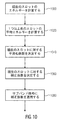
図10は、図9のステップのシーケンスの実施態様の好ましいプロシージャを示す。ステップ1000において、現在のスロットのエネルギーが計算される。次に、ステップ1020において、1つ以上の前のスロットの平均エネルギーが計算される。次に、ステップ1040において、現在のスロットに対する平滑化係数がブロック1000と1020によって得られた値の差分に基づいて決定される。次に、ステップ1060は現在のスロットに対する補正係数の計算を備え、ステップ1000〜1060は、全て制御装置800によって実行される。次に、信号生成器200によって実行されるステップ1080において実際の平滑化演算が実行される、すなわち、対応する補正係数が1つのスロット内の全てのサブバンド信号に対して適用される。
FIG. 10 shows a preferred procedure for the embodiment of the sequence of steps of FIG. In
実施形態において、時間的平滑化が以下の2つのステップにおいて実行される。 In an embodiment, temporal smoothing is performed in the following two steps:
平滑化強度についての決定:平滑化強度についての決定に対して、時間上の信号の定常性が評価される。この評価を実行する可能な方法は、現在の短期ウインドウまたはQMF時間スロットのエネルギーを前の短期ウインドウまたはQMF時間スロットの平均エネルギー値と比較することである。煩雑性についてセーブするため、これは、ハイバンド部分のみに対して評価されてもよい。比較されたエネルギー値が近いほど、平滑化の強度は低くあるべきである。これは、平滑化係数a、ここで0<a≦1、において反映される。aが大きいほど、平滑化の強度は高い。 Determination for smoothing strength: For the determination of the smoothing strength, the stationarity of the signal over time is evaluated. A possible way to perform this evaluation is to compare the energy of the current short-term window or QMF time slot with the average energy value of the previous short-term window or QMF time slot. In order to save on complexity, this may only be evaluated for the high band part. The closer the compared energy values, the lower the smoothing strength. This is reflected in the smoothing factor a, where 0 <a ≦ 1. The larger a is, the higher the smoothing strength is.
ハイバンドへの平滑化の適用:平滑化は、QMF時間スロットベースのハイバンド部分に対して適用される。それ故に、現在の時間スロットのハイバンドエネルギーEcurrtは、次のように1つまたは多数の前のQMF時間スロットの平均ハイバンドエネルギーEavgtに適応される。
![]()
Ecurrは、次のように1つの時間スロットにおけるハイバンドQMFエネルギーの合計として計算される。
Eavgは、次のようにエネルギーの時間上の移動平均である。
ここで、startおよびstopは移動平均の計算に対して用いられるインターバルの境界である。
Applying smoothing to the high band: Smoothing is applied to the high band part of the QMF time slot base. Therefore, the high band energy Ecurr t of the current time slot is adapted to the average high band energy Eav t of one or many previous QMF time slots as follows.
![]()
Ecurr is calculated as the sum of highband QMF energy in one time slot as follows.
Eavg is a moving average of energy over time as follows.
Where start and stop are the boundaries of the interval used for the moving average calculation.
合成に対して用いられる実数および虚数のQMF値は、次のように補正係数currFacで乗算され、
これは、次のようにEcurrおよびEavgから導き出される。
This is derived from Ecurr and Eavg as follows:
係数aは、固定としてもよく、またはEcurrとEavgのエネルギーの差分に従属するようにしてもよい。 The coefficient a may be fixed, or may be dependent on the energy difference between Ecurr and Eavg.
既に図14で述べられたように、時間的平滑化に対する時間分解能は、整形の時間分解能またはエネルギー制限技術の時間分解能より高くなるようにセットされる。これは、サブバンド信号の時間的に滑らかなコースが得られる一方、同時に、演算的により強い整形がフレーム当り1回のみ実行されることを確保する。しかしながら、これは、これまでに見られたように、主観的なリスニング品質を実質的に低下させるので、1つのサブバンドから他のサブバンドへの、すなわち周波数方向におけるいかなる平滑化も実行されない。 As already mentioned in FIG. 14, the time resolution for temporal smoothing is set to be higher than the time resolution of shaping or the time resolution of the energy limiting technique. This ensures that a temporally smooth course of the subband signal is obtained, while at the same time a computationally stronger shaping is performed only once per frame. However, as has been seen so far, it substantially reduces the subjective listening quality, so no smoothing from one subband to another, ie in the frequency direction, is performed.
増強レンジにおいて、全てのサブバンドに対する補正係数のような同じ平滑化情報を用いることが好ましい。しかしながら、同じ平滑化情報が全てのサブバンドに対してではなく、少なくとも2つのサブバンドを持つバンドのグループに対して適用される実施態様とすることもできる。 In the enhancement range, it is preferable to use the same smoothing information such as correction factors for all subbands. However, an embodiment in which the same smoothing information is applied not to all subbands but to a group of bands having at least two subbands is also possible.
図11は、図1に示されたエネルギー制限技術208に向けられる更なる態様を示す。具体的には、図11は、周波数増強信号130を生成する信号生成器200を備える周波数が増強された信号140を生成する装置を示し、周波数増強信号130はコア信号120に含まれない増強周波数レンジを備える。さらにまた、周波数増強信号130の時間部分は複数のサブバンドに対するサブバンド信号を備える。加えて、装置は、周波数増強信号130を用いて周波数が増強された信号140を生成する合成フィルタバンク300を備える。
FIG. 11 shows a further aspect directed to the
エネルギー制限プロシージャを実施するために、信号生成器200は、合成フィルタバンク300によって得られる周波数増強信号140が、高いバンドのエネルギーが低いバンドにおけるエネルギーに多くとも等しい、または低いバンドにおけるエネルギーより多くとも所定の閾値だけ大きいことを確保するため、エネルギー制限を実行するように構成される。
To perform the energy limiting procedure, the
信号生成器は、高いQMFサブバンドkがQMFサブバンドk−1におけるエネルギーを上回ってはならないことを確保するように、好ましくは実施される。それにもかかわらず、信号生成器200は、好ましくは3dBの閾値とすることができる特定の増分の増加を許容するように実施することもでき、閾値は好ましくは2dBとすることができ、より好ましくは1dBまたはさらに小さいものとすることができる。所定の閾値は、各バンドに対して一定とすることができる、または前に計算されたスペクトル重心に従属させることもできる。好ましい従属は、重心が低い周波数に近づくとき、閾値が低くなる、すなわち小さくなることであり、その一方で重心が高い周波数に近づくほどまたはspが1に近づくほど、閾値は小さくなることができる。
The signal generator is preferably implemented to ensure that the high QMF subband k should not exceed the energy in QMF subband k-1. Nevertheless, the
更なる実施態様において、信号生成器200は、第1のサブバンドにおける第1のサブバンド信号を検査し、周波数において第1のサブバンドに隣接し、第1のサブバンドの中心周波数より高い中心周波数を持つ第2のサブバンドにおけるサブバンド信号を検査するように構成され、信号生成器は、第2のサブバンド信号のエネルギーが第1のサブバンド信号のエネルギーと等しいとき、または第2のサブバンド信号のエネルギーが第1のサブバンド信号のエネルギーより所定の閾値未満で大きいとき、第2のサブバンド信号を制限しない。
In a further embodiment, the
さらにまた、信号生成器は、例えば図1または図2a〜2cにおいて示されたように、シーケンスにおいて複数の処理演算を形成するように構成される。次に、信号生成器は、好ましくはシーケンスの最後においてエネルギー制限を実行し、合成フィルタバンク300に入力される周波数増強信号130を取得する。従って、合成フィルタバンク300は、入力として、エネルギー制限の最終プロセスによってシーケンスの最後に生成される周波数増強信号130を受信するように構成される。
Furthermore, the signal generator is configured to form a plurality of processing operations in the sequence, eg, as shown in FIG. 1 or FIGS. 2a-2c. The signal generator then performs an energy limit, preferably at the end of the sequence, to obtain a
さらにまた、信号生成器は、エネルギー制限の前にスペクトル整形204または時間的平滑化206を実行するように構成される。 Furthermore, the signal generator is configured to perform spectral shaping 204 or temporal smoothing 206 prior to energy limiting.
好ましい実施形態において、信号生成器200は、コア信号の複数のサブバンドをミラーリングすることによって周波数増強信号の複数のサブバンド信号を生成するように構成される。
In a preferred embodiment, the
ミラーリングに対しては、好ましくは、上述されたように実部または虚部のいずれかを無効にするプロシージャが実行される。 For mirroring, a procedure is preferably performed that invalidates either the real part or the imaginary part as described above.
更なる実施形態において、信号生成器は、補正係数limFacを計算するように構成され、この制限係数limFacは次に以下のようにコアまたは増強周波数レンジのサブバンド信号に適用される。 In a further embodiment, the signal generator is configured to calculate a correction factor limFac, which is then applied to the core or enhancement frequency range subband signal as follows.
Efを、次式のように時間スパンstop−startを通じて平均化された1つのバンドのエネルギーとする。
Let E f be the energy of one band averaged over the time span stop-start as:
このエネルギーが前のバンドの平均エネルギーを数レベルだけ超える場合、このバンドのエネルギーは次の補正/制限係数limFacによって乗算され、
実部と虚部のQMF値は、次式によって補正される。
If this energy exceeds the average energy of the previous band by a few levels, the energy of this band is multiplied by the next correction / limit factor limFac,
The QMF values of the real part and the imaginary part are corrected by the following equation.
係数または所定の閾値facは、各バンドに対して一定とすることができ、または前に計算されたスペクトル重心に従属させることができる。 The coefficient or predetermined threshold fac can be constant for each band, or can be dependent on the previously calculated spectral centroid.
他の実施態様において、制限係数limFacは以下の式を用いて計算される。
この式において、Elimは、通常は低いバンドのエネルギーまたは特定の閾値facによって増加する低いバンドのエネルギーである制限エネルギーである。Ef(i)は、現在のバンドfまたはiのエネルギーである。 In this equation, E lim is the limiting energy, usually the low band energy or the low band energy that increases with a certain threshold fac. E f (i) is the energy of the current band f or i.
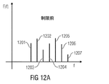
増強周波数レンジに7つのバンドがある特定の例を示す図12aと12bを参照されたい。バンド1202は、エネルギーに関してバンド1201より大きい。従って、図12bから明らかになるように、バンド1202は、このバンドに対して図12bにおいて1250で示されるようにエネルギー制限される。さらにまた、バンド1205、1204および1206は、全てバンド1203より大きい。従って、全ての3つのバンドは、図12bにおいて1250で示されるようにエネルギー制限される。残された非制限バンドは、バンド1201(これは再構成レンジにおける第1のバンドである)およびバンド1203および1207である。
See FIGS. 12a and 12b which show a specific example where there are seven bands in the enhanced frequency range.
上述したように、図12a/12bは、制限が、高いバンドが低いバンドより多くのエネルギーを持ってはならない状況を示す。しかしながら、特定の増加が許容された場合に、状況はやや異なるように見えるだろう。 As mentioned above, FIGS. 12a / 12b show a situation where the limit should not have more energy in the higher band than in the lower band. However, the situation will look slightly different if certain increases are allowed.
エネルギー制限は、単一の拡張バンドに対して適用することができる。次に、比較またはエネルギー制限が、最も高いコアバンドのエネルギーを用いてなされる。これは、複数の拡張バンドに対して適用することもできる。次に、最も低い拡張バンドは最も高いコアバンドを用いてエネルギー制限され、最も高い拡張バンドは最も高い拡張バンドの次に関してエネルギー制限される。 The energy limit can be applied to a single extension band. A comparison or energy limit is then made using the highest core band energy. This can also be applied to multiple extension bands. The lowest extension band is then energy limited with the highest core band, and the highest extension band is energy limited with respect to the next of the highest extension band.
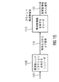
図15は、伝送システムまたは、一般に、エンコーダ1500およびデコーダ1510を備えるシステムを示す。エンコーダは、好ましくは、バンド幅リダクションを実行する、または一般にオリジナルのオーディオ信号1501において、必ずしも完全な上側周波数レンジまたは上側バンドでなければならない必要がないが、コアの周波数バンド間においていかなる周波数バンドとすることもできる、いくつかの周波数レンジを削除する符号化されたコア信号を生成するエンコーダである。次に、符号化されたコア信号は、エンコーダ1500からデコーダ1510にいかなるサイド情報もなしに伝送され、デコーダ1510は、次に周波数が増強された信号140を得るために非ガイド式の周波数増強を実行する。従って、デコーダは、図1〜14のいずれかで述べたように実施することができる。
FIG. 15 shows a transmission system or, in general, a system comprising an
本発明は、ブロックが現実のまたは論理的なハードウェアコンポーネントを表すブロック図の局面において述べられたが、本発明は、コンピュータで実施される方法によって実施することもできる。後者のケースにおいて、ブロックは対応する方法ステップを表し、ここでこれらのステップは対応する論理的または物理的ハードウェアブロックによって実行される機能を表す。 Although the invention has been described in terms of block diagrams where blocks represent real or logical hardware components, the invention can also be implemented by computer-implemented methods. In the latter case, blocks represent corresponding method steps, where these steps represent functions performed by corresponding logical or physical hardware blocks.
いくつかの態様が装置の局面において記述されてきたが、これらの態様は対応する方法の記述をも表していることは明らかであり、ここでブロックまたはデバイスは、方法ステップまたは方法ステップの特徴に対応する。同様に、方法ステップの局面において記述された態様は、対応する装置の対応するブロックまたはアイテムまたは特徴の記載をも表す。いくつかの、または全ての方法ステップは、例えばマイクロプロセッサ、プログラム可能なコンピュータまたは電子回路のようなハードウェア装置によって(または用いて)実行することができる。いくつかの実施形態において、いくつかの1つ以上の最も重要な方法ステップは、この種の装置によって実行することができる。 Although several embodiments have been described in the apparatus aspect, it is clear that these embodiments also represent a description of the corresponding method, where a block or device is a method step or feature of a method step. Correspond. Similarly, the embodiments described in the method step aspects also represent descriptions of corresponding blocks or items or features of corresponding devices. Some or all method steps may be performed (or used) by a hardware device such as, for example, a microprocessor, programmable computer or electronic circuit. In some embodiments, some one or more of the most important method steps can be performed by such an apparatus.
本発明の送信されたまたは符号化された信号は、デジタル記憶媒体に記憶することができ、または例えばインターネットのような無線伝送路または有線伝送路のような伝送路上を送信することができる。 The transmitted or encoded signal of the present invention can be stored in a digital storage medium or transmitted over a transmission line such as a wireless transmission line such as the Internet or a wired transmission line.
特定の実施要求に依存して、本発明の実施形態は、ハードウェアにおいてまたはソフトウェアにおいて実施することができる。実施は、その上に記憶される電子的に読取可能な制御信号を持ち、それぞれの方法が実行されるようにプログラム可能なコンピュータシステムと協働する(または協働することができる)デジタル記憶媒体、例えばフロッピー(登録商標)ディスク、DVD、ブルーレイ、CD、ROM、PROMおよびEPROM、EEPROMまたはフラッシュメモリを用いて実行することができる。それ故に、デジタル記憶媒体はコンピュータ読取可能とすることができる。 Depending on certain implementation requirements, embodiments of the invention can be implemented in hardware or in software. An implementation has an electronically readable control signal stored thereon and cooperates with (or can cooperate with) a computer system that is programmable such that the respective method is performed. For example, using a floppy disk, DVD, Blu-ray, CD, ROM, PROM and EPROM, EEPROM or flash memory. Therefore, the digital storage medium can be computer readable.
本発明によるいくつかの実施形態は、本願明細書に記載された方法の1つが実行されるように、電子的に読取可能な制御信号を持ち、プログラム可能なコンピュータシステムと協働することができるデータキャリアを備える。 Some embodiments according to the present invention have electronically readable control signals and can work with a programmable computer system so that one of the methods described herein is performed. Provide a data carrier.
一般に、本発明の実施形態は、コンピュータプログラム製品がコンピュータ上で動作するときに発明の方法の1つを実行するように動作するプログラムコードを有するコンピュータプログラム製品として実施することができる。プログラムコードは、例えば機械読取可能なキャリア上に記憶することができる。 In general, embodiments of the present invention may be implemented as a computer program product having program code that operates to perform one of the inventive methods when the computer program product runs on a computer. The program code can be stored, for example, on a machine readable carrier.
他の実施形態は、機械読取可能なキャリア上に記憶され、本願明細書に記載された方法の1つを実行するコンピュータプログラムを備える。 Other embodiments comprise a computer program that is stored on a machine-readable carrier and that performs one of the methods described herein.
換言すれば、本発明の方法の実施形態は、それ故に、コンピュータプログラムがコンピュータ上で動作するとき、本願明細書に記載された方法の1つを実行するプログラムコードを持つコンピュータプログラムである。 In other words, the method embodiment of the present invention is therefore a computer program with program code that performs one of the methods described herein when the computer program runs on a computer.
発明の方法の更なる実施形態は、それ故に、その上に記録され、本願明細書に記載された方法の1つを実行するコンピュータプログラムを備えるデータキャリア(またはデジタル記憶媒体またはコンピュータ読取可能媒体のような固定の記憶媒体)である。データキャリア、デジタル記憶媒体または記録媒体は、通常は有形および/または固定である。 A further embodiment of the method of the invention is therefore a data carrier (or a digital storage medium or a computer readable medium) comprising a computer program recorded thereon and performing one of the methods described herein. Such as a fixed storage medium). A data carrier, digital storage medium or recording medium is usually tangible and / or fixed.
本発明の方法の更なる実施形態は、それ故に、本願明細書に記載された方法の1つを実行するコンピュータプログラムを表すデータストリームまたは信号のシーケンスである。データストリームまたは信号のシーケンスは、例えばデータ通信接続を介して、例えばインターネットを介して伝送されるように構成することができる。 A further embodiment of the method of the present invention is therefore a data stream or a sequence of signals representing a computer program that performs one of the methods described herein. The data stream or the sequence of signals can be configured to be transmitted over a data communication connection, for example, over the Internet.
更なる実施形態は、本願明細書に記載された方法の1つを実行するように構成されたまたは適応された処理手段、例えばコンピュータまたはプログラマブルロジックデバイスを備える。 Further embodiments comprise processing means, such as a computer or programmable logic device, configured or adapted to perform one of the methods described herein.
更なる実施形態は、本願明細書に記載された方法の1つを実行するコンピュータプログラムがその上にインストールされたコンピュータを備える。 Further embodiments comprise a computer having a computer program installed thereon for performing one of the methods described herein.
本発明による更なる実施形態は、本願明細書に記載された方法の1つを実行するコンピュータプログラムをレシーバに(例えば電子的にまたは光学的に)伝送するように構成された装置またはシステムを備える。レシーバは、例えばコンピュータ、モバイルデバイス、記憶デバイス等とすることができる。装置またはシステムは、例えばコンピュータプログラムをレシーバへ転送するファイルサーバを備えることができる。 Further embodiments according to the present invention comprise an apparatus or system configured to transmit (eg, electronically or optically) a computer program that performs one of the methods described herein to a receiver. . The receiver can be, for example, a computer, a mobile device, a storage device, or the like. The apparatus or system may comprise a file server that transfers the computer program to the receiver, for example.
いくつかの実施形態において、本願明細書に記載された方法の機能のいくつかまたは全てを実行するために、プログラマブルロジックデバイス(例えばフィールドプログラマブルゲートアレイ)を用いることができる。いくつかの実施形態において、フィールドプログラマブルゲートアレイは、本願明細書に記載された方法の1つを実行するために、マイクロプロセッサと協働することができる。一般に、方法は、好ましくはいかなるハードウェア装置によっても実行される。 In some embodiments, a programmable logic device (eg, a field programmable gate array) can be used to perform some or all of the functions of the methods described herein. In some embodiments, the field programmable gate array can cooperate with a microprocessor to perform one of the methods described herein. In general, the method is preferably performed by any hardware device.
上述した実施形態は、単に本発明の原理に対して示したものである。本願明細書に記載された構成および詳細の修正および変更は他の当業者にとって明らかであると理解される。それ故に、本発明は、以下の特許請求の範囲のスコープによってのみ制限され、本願明細書の実施形態の記載および説明によって提供された特定の詳細によっては制限されないことを意図する。 The above-described embodiments are merely illustrative for the principles of the present invention. It will be understood that modifications and variations in configuration and details described herein will be apparent to other persons skilled in the art. Therefore, it is intended that this invention be limited only by the scope of the following claims and not by the specific details provided by the description and description of the embodiments herein.
Claims (16)
コア信号(502)における周波数に関するエネルギー分布を記述する値を計算する、計算器(500)と、
前記コア信号(502)に含まれない増強周波数レンジを備える前記周波数増強信号(130)を前記コア信号(502)から生成する、信号生成器(200)と、
を備え、
前記信号生成器(200)は、前記周波数増強信号(130)のまたは前記コア信号(502)のスペクトル包絡が前記コア信号(502)における周波数に関するエネルギー分布を記述する値(501)に従属するように、前記周波数増強信号(130)または前記コア信号(502)を整形するように構成され、
前記信号生成器(200)は、第1のエネルギー分布を記述する第1の値に対して、前記増強周波数レンジにおける第1の周波数から前記増強周波数レンジにおける第2の周波数への第1のスペクトル包絡の減少が得られ、且つ、第2のエネルギー分布を記述する第2の値に対して、前記増強周波数レンジにおける前記第1の周波数から前記増強周波数レンジにおける前記第2の周波数への第2のスペクトル包絡の減少が得られるように、前記周波数増強信号(130)または前記コア信号(502)を整形するように構成され、
前記第2の周波数は、前記第1の周波数より大きく、
前記第2のスペクトル包絡の減少は、前記第1のスペクトル包絡の減少より大きく、
前記第1の値は、前記第2の値と比較して、前記コア信号が前記コア信号のより高い周波数においてエネルギー集中を持つことを示す、
装置。 An apparatus for generating a frequency enhancement signal ( 130 ) comprising:
A calculator (500) for calculating a value describing an energy distribution with respect to frequency in the core signal (502);
The frequency enhancement signal comprising enhanced frequency range not included in the prior SL core signal (502) (130) generated from the core signal (502), the signal generator (200),
With
The signal generator (200) is such that the spectral envelope of the frequency enhancement signal (130) or of the core signal (502) is dependent on a value (501) describing an energy distribution with respect to frequency in the core signal (502). Configured to shape the frequency enhancement signal (130) or the core signal (502),
Said signal generator (200), the first value describing a first energy distribution, from the first frequency in the enhanced frequency range first to a second frequency in the enhancement frequency ranges reduction of the spectral envelope is obtained, and, with respect to a second value describing the second energy distribution, from the first frequency in the enhanced frequency range to the second frequency in the enhancement frequency ranges Configured to shape the frequency enhancement signal (130) or the core signal (502) to obtain a second spectral envelope reduction;
The second frequency is greater than the first frequency;
The decrease in the second spectral envelope is greater than the decrease in the first spectral envelope;
The first value indicates that the core signal has an energy concentration at a higher frequency of the core signal compared to the second value;
apparatus.
前記信号生成器(200)は、高い周波数におけるスペクトル重心が低い周波数におけるスペクトル重心より浅い勾配のスペクトル包絡に結果としてなるように、前記スペクトル重心に対する尺度に従って整形するように構成された、
請求項1または2に記載の装置。 It said calculator (500) is a value that describes the energy distribution, is configured to calculate a measure for the spectral centroid of the current frame,
The signal generator (200) is configured to shape according to a measure for the spectral centroid, such that the spectral centroid at a high frequency results in a spectral envelope with a shallower slope than the spectral centroid at a low frequency.
The apparatus according to claim 1 or 2.
請求項1〜4のいずれかに記載の装置。 The value describing the energy distribution is calculated using the following formula:
The apparatus according to claim 1.
att=p(sp)
ここで、attは、整形係数を支配する値であり、pは多項式であり、spは前記計算器(500)によって計算される前記エネルギー分布を記述する値である、
請求項1〜5のいずれかに記載の装置。 The signal generator is configured to apply a shaping factor to the input signal, the shaping factor being calculated based on the following equation:
att = p (sp)
Here, att is a value that governs the shaping factor, p is a polynomial, sp is the value describing the energy distribution is calculated by the calculator (500),
The device according to claim 1.
前記計算器(500)は、前記コア信号サブバンドの個々のエネルギーを計算し、前記個々のエネルギー(604)を用いて前記エネルギー分布を記述する値を計算するように構成された、
請求項1〜7のいずれかに記載の装置。 The core signal (502) comprises a plurality of core signal subbands,
The calculator (500) is configured to calculate individual energies of the core signal subbands and to calculate values describing the energy distribution using the individual energies (604);
The apparatus according to claim 1.
前記信号生成器(200)は、1つ以上のコア信号バンドをコピーアップまたはミラーリング(202)して、前記増強周波数レンジを形成する複数の増強信号バンドを取得するように構成された、
請求項1〜8のいずれかに記載の装置。 The core signal (502) comprises a plurality of core signal bands,
Said signal generator (200), one or more core signal band a copy-up or mirroring (202) that is configured to acquire a plurality of enhancement signals band forming the enhancement frequency range,
The apparatus according to claim 1.
請求項1に記載の装置。 The calculator (500) is configured to calculate the value based on the following equation:
The apparatus of claim 1.
請求項1〜10のいずれかに記載の装置。 Said signal generator (200), as time other subsequent to shaping (204) of said frequency enhancement signal (130) or the core signal (502) executes the same time, temporal smoothing operation (206) is configured, the temporal smoothing operation includes the steps of searching for a decision about the smoothing intensity, and based on the said determination, the time before distichum wavenumber enhancement signal (130) or the core signal (502) comprising the step of applying a smoothing operation (206),
The apparatus according to claim 1.
または時間的平滑化演算(206)に引き続いてバンドワイズのエネルギー制限(208)を適用する、
または前記周波数増強信号(130)または前記コア信号(502)の前記整形(204)と同時に、バンドワイズのエネルギー制限(208)を適用する、
または時間的平滑化演算(206)と同時に、バンドワイズのエネルギー制限(208)を適用するように構成された、
請求項1〜11のいずれかに記載の装置。 The signal generator (200) applies a bandwidth energy limit (208) following the shaping (204) of the frequency enhancement signal (130) or the core signal (502) .
Or apply an energy limit of bandwidth (the 208) subsequent to the time during smoothing operation (206),
Or applying a bandwidth energy limit (208) simultaneously with the shaping (204) of the frequency enhancement signal (130) or the core signal (502) ,
Or at the same time smoothing operation (206) during time, which is configured to apply energy limit of bandwidth (208),
The apparatus according to claim 1.
コア信号(502)における周波数に関するエネルギー分布を記述する値を計算するステップ(500)と、
前記コア信号(502)に含まれない増強周波数レンジを備える前記周波数増強信号(130)を前記コア信号(502)から生成するステップ(200)と、
を備え、
前記周波数増強信号(130)を生成する前記ステップ(200)は、前記周波数増強信号(130)のまたは前記コア信号(502)のスペクトル包絡が前記コア信号(502)における周波数に関するエネルギー分布を記述する値(501)に従属するように、前記周波数増強信号(130)または前記コア信号(502)を整形するステップを備え、
前記周波数増強信号(130)を生成するステップ(200)は、第1のエネルギー分布を記述する第1の値に対して、前記増強周波数レンジにおける第1の周波数から前記増強周波数レンジにおける第2の周波数への第1のスペクトル包絡の減少が得られ、且つ、第2のエネルギー分布を記述する第2の値に対して、前記増強周波数レンジにおける前記第1の周波数から前記増強周波数レンジにおける前記第2の周波数への第2のスペクトル包絡の減少が得られるように、前記周波数増強信号(130)または前記コア信号(502)を整形するステップを備え、
前記第2の周波数は、前記第1の周波数より大きく、
前記第2のスペクトル包絡の減少は、前記第1のスペクトル包絡の減少より大きく、
前記第1の値は、前記第2の値と比較して、前記コア信号(502)が前記コア信号(502)のより高い周波数においてエネルギー集中を持つことを示す、
方法。 A method for generating a frequency enhancement signal (130) comprising:
Calculating (500) a value describing a frequency energy distribution in the core signal (502);
A step (200) for generating said frequency enhancement signal comprising enhanced frequency range not included in the prior SL core signal (502) to (130) from the core signal (502),
With
It said step of said frequency enhancing signal (130) to generate (200), describes the energy distribution for the frequency in the spectrum envelope is the core signal (502) or the core signal of the frequency enhancement signal (130) (502) Shaping the frequency enhancement signal (130) or the core signal (502) to depend on a value (501) to
The step (200) of generating the frequency enhancement signal (130) includes, for a first value describing a first energy distribution, from a first frequency in the enhancement frequency range to a second in the enhancement frequency range. A reduction of the first spectral envelope to frequency is obtained and the second value describing the second energy distribution is compared to the first frequency in the enhanced frequency range from the first frequency in the enhanced frequency range. as reduction of the second spectral envelope to the second frequency is obtained, comprising the step of shaping the frequency enhancement signal (130) or the core signal (502),
The second frequency is greater than the first frequency;
The decrease in the second spectral envelope is greater than the decrease in the first spectral envelope;
The first value indicates that the core signal (502) has an energy concentration at a higher frequency of the core signal (502) compared to the second value;
Method.
符号化されたコア信号(502)を生成する、エンコーダ(1500)と、
請求項1〜12のいずれかに記載の周波数増強信号(130)を生成する装置と、
を備えた、システム。 A system for processing audio signals,
An encoder (1500) for generating an encoded core signal (502);
An apparatus for generating a frequency enhancement signal (130) according to any of the preceding claims;
With a system.
符号化されたコア信号(502)を生成するステップ(1500)と、
請求項13に記載の方法に従って周波数増強信号(130)を生成するステップと、
を備えた、方法。 A method of processing an audio signal, comprising:
Generating (1500) an encoded core signal (502);
Generating a frequency enhancement signal (130) according to the method of claim 13;
With a method.
Applications Claiming Priority (3)
| Application Number | Priority Date | Filing Date | Title |
|---|---|---|---|
| US201361758090P | 2013-01-29 | 2013-01-29 | |
| US61/758,090 | 2013-01-29 | ||
| PCT/EP2014/051599 WO2014118159A1 (en) | 2013-01-29 | 2014-01-28 | Apparatus and method for generating a frequency enhanced signal using shaping of the enhancement signal |
Publications (2)
| Publication Number | Publication Date |
|---|---|
| JP2016510428A JP2016510428A (en) | 2016-04-07 |
| JP6301368B2 true JP6301368B2 (en) | 2018-03-28 |
Family
ID=50029033
Family Applications (3)
| Application Number | Title | Priority Date | Filing Date |
|---|---|---|---|
| JP2015555675A Active JP6289507B2 (en) | 2013-01-29 | 2014-01-28 | Apparatus and method for generating a frequency enhancement signal using an energy limiting operation |
| JP2015555673A Active JP6301368B2 (en) | 2013-01-29 | 2014-01-28 | Apparatus and method for generating a frequency enhancement signal using enhancement signal shaping |
| JP2015555674A Active JP6321684B2 (en) | 2013-01-29 | 2014-01-28 | Apparatus and method for generating frequency enhancement signals using temporal smoothing of subbands |
Family Applications Before (1)
| Application Number | Title | Priority Date | Filing Date |
|---|---|---|---|
| JP2015555675A Active JP6289507B2 (en) | 2013-01-29 | 2014-01-28 | Apparatus and method for generating a frequency enhancement signal using an energy limiting operation |
Family Applications After (1)
| Application Number | Title | Priority Date | Filing Date |
|---|---|---|---|
| JP2015555674A Active JP6321684B2 (en) | 2013-01-29 | 2014-01-28 | Apparatus and method for generating frequency enhancement signals using temporal smoothing of subbands |
Country Status (20)
| Country | Link |
|---|---|
| US (4) | US9552823B2 (en) |
| EP (4) | EP2951825B1 (en) |
| JP (3) | JP6289507B2 (en) |
| KR (3) | KR101787497B1 (en) |
| CN (3) | CN105264601B (en) |
| AR (3) | AR094670A1 (en) |
| AU (3) | AU2014211527B2 (en) |
| BR (2) | BR112015017868B1 (en) |
| CA (3) | CA2899080C (en) |
| ES (3) | ES2899781T3 (en) |
| HK (2) | HK1218019A1 (en) |
| MX (3) | MX346945B (en) |
| MY (3) | MY185159A (en) |
| PL (1) | PL2951825T3 (en) |
| PT (1) | PT2951825T (en) |
| RU (3) | RU2625945C2 (en) |
| SG (3) | SG11201505883WA (en) |
| TW (2) | TWI529701B (en) |
| WO (3) | WO2014118161A1 (en) |
| ZA (2) | ZA201506265B (en) |
Families Citing this family (7)
| Publication number | Priority date | Publication date | Assignee | Title |
|---|---|---|---|---|
| MX346945B (en) | 2013-01-29 | 2017-04-06 | Fraunhofer Ges Forschung | Apparatus and method for generating a frequency enhancement signal using an energy limitation operation. |
| TWI557727B (en) | 2013-04-05 | 2016-11-11 | 杜比國際公司 | An audio processing system, a multimedia processing system, a method of processing an audio bitstream and a computer program product |
| US9418671B2 (en) * | 2013-08-15 | 2016-08-16 | Huawei Technologies Co., Ltd. | Adaptive high-pass post-filter |
| US10146500B2 (en) * | 2016-08-31 | 2018-12-04 | Dts, Inc. | Transform-based audio codec and method with subband energy smoothing |
| US10825467B2 (en) * | 2017-04-21 | 2020-11-03 | Qualcomm Incorporated | Non-harmonic speech detection and bandwidth extension in a multi-source environment |
| EP3671741A1 (en) * | 2018-12-21 | 2020-06-24 | FRAUNHOFER-GESELLSCHAFT zur Förderung der angewandten Forschung e.V. | Audio processor and method for generating a frequency-enhanced audio signal using pulse processing |
| CN109841223B (en) * | 2019-03-06 | 2020-11-24 | 深圳大学 | Audio signal processing method, intelligent terminal and storage medium |
Family Cites Families (55)
| Publication number | Priority date | Publication date | Assignee | Title |
|---|---|---|---|---|
| US2009A (en) * | 1841-03-18 | Improvement in machines for boring war-rockets | ||
| US5765127A (en) * | 1992-03-18 | 1998-06-09 | Sony Corp | High efficiency encoding method |
| US5581653A (en) | 1993-08-31 | 1996-12-03 | Dolby Laboratories Licensing Corporation | Low bit-rate high-resolution spectral envelope coding for audio encoder and decoder |
| US20020002455A1 (en) | 1998-01-09 | 2002-01-03 | At&T Corporation | Core estimator and adaptive gains from signal to noise ratio in a hybrid speech enhancement system |
| SE0004163D0 (en) * | 2000-11-14 | 2000-11-14 | Coding Technologies Sweden Ab | Enhancing perceptual performance or high frequency reconstruction coding methods by adaptive filtering |
| US7197458B2 (en) * | 2001-05-10 | 2007-03-27 | Warner Music Group, Inc. | Method and system for verifying derivative digital files automatically |
| US7555434B2 (en) * | 2002-07-19 | 2009-06-30 | Nec Corporation | Audio decoding device, decoding method, and program |
| US7318035B2 (en) | 2003-05-08 | 2008-01-08 | Dolby Laboratories Licensing Corporation | Audio coding systems and methods using spectral component coupling and spectral component regeneration |
| JPWO2005106848A1 (en) | 2004-04-30 | 2007-12-13 | 松下電器産業株式会社 | Scalable decoding apparatus and enhancement layer erasure concealment method |
| JP4168976B2 (en) * | 2004-05-28 | 2008-10-22 | ソニー株式会社 | Audio signal encoding apparatus and method |
| JP4771674B2 (en) | 2004-09-02 | 2011-09-14 | パナソニック株式会社 | Speech coding apparatus, speech decoding apparatus, and methods thereof |
| SE0402652D0 (en) | 2004-11-02 | 2004-11-02 | Coding Tech Ab | Methods for improved performance of prediction based multi-channel reconstruction |
| US8249861B2 (en) * | 2005-04-20 | 2012-08-21 | Qnx Software Systems Limited | High frequency compression integration |
| US8260609B2 (en) | 2006-07-31 | 2012-09-04 | Qualcomm Incorporated | Systems, methods, and apparatus for wideband encoding and decoding of inactive frames |
| WO2008062990A1 (en) | 2006-11-21 | 2008-05-29 | Samsung Electronics Co., Ltd. | Method, medium, and system scalably encoding/decoding audio/speech |
| KR101355376B1 (en) | 2007-04-30 | 2014-01-23 | 삼성전자주식회사 | Method and apparatus for encoding and decoding high frequency band |
| US20110022924A1 (en) | 2007-06-14 | 2011-01-27 | Vladimir Malenovsky | Device and Method for Frame Erasure Concealment in a PCM Codec Interoperable with the ITU-T Recommendation G. 711 |
| US8209190B2 (en) | 2007-10-25 | 2012-06-26 | Motorola Mobility, Inc. | Method and apparatus for generating an enhancement layer within an audio coding system |
| US8504377B2 (en) * | 2007-11-21 | 2013-08-06 | Lg Electronics Inc. | Method and an apparatus for processing a signal using length-adjusted window |
| US8554551B2 (en) | 2008-01-28 | 2013-10-08 | Qualcomm Incorporated | Systems, methods, and apparatus for context replacement by audio level |
| DE102008015702B4 (en) * | 2008-01-31 | 2010-03-11 | Fraunhofer-Gesellschaft zur Förderung der angewandten Forschung e.V. | Apparatus and method for bandwidth expansion of an audio signal |
| US20090201983A1 (en) * | 2008-02-07 | 2009-08-13 | Motorola, Inc. | Method and apparatus for estimating high-band energy in a bandwidth extension system |
| CN101335000B (en) * | 2008-03-26 | 2010-04-21 | 华为技术有限公司 | Method and apparatus for encoding |
| CN101281748B (en) * | 2008-05-14 | 2011-06-15 | 武汉大学 | Method for filling opening son (sub) tape using encoding index as well as method for generating encoding index |
| EP2144230A1 (en) | 2008-07-11 | 2010-01-13 | Fraunhofer-Gesellschaft zur Förderung der angewandten Forschung e.V. | Low bitrate audio encoding/decoding scheme having cascaded switches |
| MY155538A (en) * | 2008-07-11 | 2015-10-30 | Fraunhofer Ges Forschung | An apparatus and a method for generating bandwidth extension output data |
| BRPI0904958B1 (en) * | 2008-07-11 | 2020-03-03 | Fraunhofer-Gesellschaft Zur Foerderung Der Angewandten Forschung E.V. | APPARATUS AND METHOD FOR CALCULATING BANDWIDTH EXTENSION DATA USING A TABLE CONTROLLED BY SPECTRAL TILTING |
| MX2011000375A (en) | 2008-07-11 | 2011-05-19 | Fraunhofer Ges Forschung | Audio encoder and decoder for encoding and decoding frames of sampled audio signal. |
| JP2010079275A (en) | 2008-08-29 | 2010-04-08 | Sony Corp | Device and method for expanding frequency band, device and method for encoding, device and method for decoding, and program |
| US8352279B2 (en) * | 2008-09-06 | 2013-01-08 | Huawei Technologies Co., Ltd. | Efficient temporal envelope coding approach by prediction between low band signal and high band signal |
| TWI413109B (en) | 2008-10-01 | 2013-10-21 | Dolby Lab Licensing Corp | Decorrelator for upmixing systems |
| RU2520402C2 (en) | 2008-10-08 | 2014-06-27 | Фраунхофер-Гезелльшафт Цур Фердерунг Дер Ангевандтен Форшунг Е.Ф. | Multi-resolution switched audio encoding/decoding scheme |
| FR2938688A1 (en) * | 2008-11-18 | 2010-05-21 | France Telecom | ENCODING WITH NOISE FORMING IN A HIERARCHICAL ENCODER |
| RU2523035C2 (en) * | 2008-12-15 | 2014-07-20 | Фраунхофер-Гезелльшафт цур Фёрдерунг дер ангевандтен Форшунг Е.Ф. | Audio encoder and bandwidth extension decoder |
| PL4231290T3 (en) * | 2008-12-15 | 2024-04-02 | Fraunhofer-Gesellschaft zur Förderung der angewandten Forschung e.V. | Audio bandwidth extension decoder, corresponding method and computer program |
| US8153010B2 (en) | 2009-01-12 | 2012-04-10 | American Air Liquide, Inc. | Method to inhibit scale formation in cooling circuits using carbon dioxide |
| CA3107567C (en) * | 2009-01-28 | 2022-08-02 | Dolby International Ab | Improved harmonic transposition |
| EP2214161A1 (en) * | 2009-01-28 | 2010-08-04 | Fraunhofer-Gesellschaft zur Förderung der angewandten Forschung e.V. | Apparatus, method and computer program for upmixing a downmix audio signal |
| JP4945586B2 (en) * | 2009-02-02 | 2012-06-06 | 株式会社東芝 | Signal band expander |
| JP4892021B2 (en) * | 2009-02-26 | 2012-03-07 | 株式会社東芝 | Signal band expander |
| JP4932917B2 (en) * | 2009-04-03 | 2012-05-16 | 株式会社エヌ・ティ・ティ・ドコモ | Speech decoding apparatus, speech decoding method, and speech decoding program |
| ES2452569T3 (en) * | 2009-04-08 | 2014-04-02 | Fraunhofer-Gesellschaft zur Förderung der angewandten Forschung e.V. | Device, procedure and computer program for mixing upstream audio signal with downstream mixing using phase value smoothing |
| US8392200B2 (en) | 2009-04-14 | 2013-03-05 | Qualcomm Incorporated | Low complexity spectral band replication (SBR) filterbanks |
| PL2273493T3 (en) * | 2009-06-29 | 2013-07-31 | Fraunhofer Ges Forschung | Bandwidth extension encoding and decoding |
| EP2704143B1 (en) | 2009-10-21 | 2015-01-07 | Panasonic Intellectual Property Corporation of America | Apparatus, method and computer program for audio signal processing |
| CN102612712B (en) | 2009-11-19 | 2014-03-12 | 瑞典爱立信有限公司 | Bandwidth extension of low band audio signal |
| CN102884575A (en) | 2010-04-22 | 2013-01-16 | 高通股份有限公司 | Voice activity detection |
| CA2800208C (en) * | 2010-05-25 | 2016-05-17 | Nokia Corporation | A bandwidth extender |
| US9047875B2 (en) * | 2010-07-19 | 2015-06-02 | Futurewei Technologies, Inc. | Spectrum flatness control for bandwidth extension |
| JP6075743B2 (en) * | 2010-08-03 | 2017-02-08 | ソニー株式会社 | Signal processing apparatus and method, and program |
| CN102436820B (en) | 2010-09-29 | 2013-08-28 | 华为技术有限公司 | High frequency band signal coding and decoding methods and devices |
| KR20140027091A (en) | 2011-02-08 | 2014-03-06 | 엘지전자 주식회사 | Method and device for bandwidth extension |
| US8908377B2 (en) * | 2011-07-25 | 2014-12-09 | Ibiden Co., Ltd. | Wiring board and method for manufacturing the same |
| US20130259254A1 (en) | 2012-03-28 | 2013-10-03 | Qualcomm Incorporated | Systems, methods, and apparatus for producing a directional sound field |
| MX346945B (en) | 2013-01-29 | 2017-04-06 | Fraunhofer Ges Forschung | Apparatus and method for generating a frequency enhancement signal using an energy limitation operation. |
-
2014
- 2014-01-28 MX MX2015009598A patent/MX346945B/en active IP Right Grant
- 2014-01-28 AU AU2014211527A patent/AU2014211527B2/en active Active
- 2014-01-28 JP JP2015555675A patent/JP6289507B2/en active Active
- 2014-01-28 JP JP2015555673A patent/JP6301368B2/en active Active
- 2014-01-28 RU RU2015136768A patent/RU2625945C2/en active
- 2014-01-28 SG SG11201505883WA patent/SG11201505883WA/en unknown
- 2014-01-28 BR BR112015017868-5A patent/BR112015017868B1/en active IP Right Grant
- 2014-01-28 KR KR1020157020470A patent/KR101787497B1/en active IP Right Grant
- 2014-01-28 WO PCT/EP2014/051603 patent/WO2014118161A1/en active Application Filing
- 2014-01-28 SG SG11201505906RA patent/SG11201505906RA/en unknown
- 2014-01-28 KR KR1020157022258A patent/KR101762225B1/en active IP Right Grant
- 2014-01-28 MX MX2015009536A patent/MX351191B/en active IP Right Grant
- 2014-01-28 EP EP14701750.3A patent/EP2951825B1/en active Active
- 2014-01-28 MX MX2015009597A patent/MX346944B/en active IP Right Grant
- 2014-01-28 WO PCT/EP2014/051601 patent/WO2014118160A1/en active Application Filing
- 2014-01-28 JP JP2015555674A patent/JP6321684B2/en active Active
- 2014-01-28 ES ES16190670T patent/ES2899781T3/en active Active
- 2014-01-28 CA CA2899080A patent/CA2899080C/en active Active
- 2014-01-28 RU RU2015136470A patent/RU2608447C1/en active
- 2014-01-28 CA CA2899072A patent/CA2899072C/en active Active
- 2014-01-28 AU AU2014211529A patent/AU2014211529B2/en active Active
- 2014-01-28 EP EP14702224.8A patent/EP2951826B1/en active Active
- 2014-01-28 ES ES14702224T patent/ES2914614T3/en active Active
- 2014-01-28 PL PL14701750T patent/PL2951825T3/en unknown
- 2014-01-28 EP EP14702513.4A patent/EP2951827A1/en not_active Withdrawn
- 2014-01-28 BR BR112015017632-1A patent/BR112015017632B1/en active IP Right Grant
- 2014-01-28 MY MYPI2015001894A patent/MY185159A/en unknown
- 2014-01-28 CA CA2899078A patent/CA2899078C/en active Active
- 2014-01-28 SG SG11201505908QA patent/SG11201505908QA/en unknown
- 2014-01-28 PT PT147017503T patent/PT2951825T/en unknown
- 2014-01-28 WO PCT/EP2014/051599 patent/WO2014118159A1/en active Application Filing
- 2014-01-28 CN CN201480019526.2A patent/CN105264601B/en active Active
- 2014-01-28 MY MYPI2015001892A patent/MY172710A/en unknown
- 2014-01-28 CN CN201480006625.7A patent/CN105103228B/en active Active
- 2014-01-28 ES ES14701750T patent/ES2905846T3/en active Active
- 2014-01-28 EP EP16190670.6A patent/EP3136386B1/en active Active
- 2014-01-28 KR KR1020157022257A patent/KR101757349B1/en active IP Right Grant
- 2014-01-28 AU AU2014211528A patent/AU2014211528B2/en active Active
- 2014-01-28 CN CN201480019085.6A patent/CN105229738B/en active Active
- 2014-01-28 MY MYPI2015001902A patent/MY172161A/en unknown
- 2014-01-28 RU RU2015136799A patent/RU2624104C2/en active
- 2014-01-29 AR ARP140100286A patent/AR094670A1/en active IP Right Grant
- 2014-01-29 TW TW103103521A patent/TWI529701B/en active
- 2014-01-29 AR ARP140100287A patent/AR094671A1/en active IP Right Grant
- 2014-01-29 TW TW103103525A patent/TWI524332B/en active
- 2014-01-29 AR ARP140100288A patent/AR094672A1/en active IP Right Grant
-
2015
- 2015-07-28 US US14/811,790 patent/US9552823B2/en active Active
- 2015-07-28 US US14/811,285 patent/US9640189B2/en active Active
- 2015-07-29 US US14/812,682 patent/US9741353B2/en active Active
- 2015-08-27 ZA ZA2015/06265A patent/ZA201506265B/en unknown
- 2015-08-27 ZA ZA2015/06268A patent/ZA201506268B/en unknown
-
2016
- 2016-05-25 HK HK16105948.4A patent/HK1218019A1/en unknown
- 2016-05-26 HK HK16106006.1A patent/HK1218020A1/en unknown
-
2017
- 2017-07-26 US US15/660,899 patent/US10354665B2/en active Active
Also Published As
Similar Documents
| Publication | Publication Date | Title |
|---|---|---|
| JP6301368B2 (en) | Apparatus and method for generating a frequency enhancement signal using enhancement signal shaping | |
| TWI544482B (en) | Apparatus and method for generating a frequency enhancement signal using an energy limitation operation |
Legal Events
| Date | Code | Title | Description |
|---|---|---|---|
| A131 | Notification of reasons for refusal |
Free format text: JAPANESE INTERMEDIATE CODE: A131 Effective date: 20161004 |
|
| A601 | Written request for extension of time |
Free format text: JAPANESE INTERMEDIATE CODE: A601 Effective date: 20161228 |
|
| A521 | Request for written amendment filed |
Free format text: JAPANESE INTERMEDIATE CODE: A523 Effective date: 20170404 |
|
| A131 | Notification of reasons for refusal |
Free format text: JAPANESE INTERMEDIATE CODE: A131 Effective date: 20170725 |
|
| A601 | Written request for extension of time |
Free format text: JAPANESE INTERMEDIATE CODE: A601 Effective date: 20171019 |
|
| A521 | Request for written amendment filed |
Free format text: JAPANESE INTERMEDIATE CODE: A523 Effective date: 20180125 |
|
| TRDD | Decision of grant or rejection written | ||
| A01 | Written decision to grant a patent or to grant a registration (utility model) |
Free format text: JAPANESE INTERMEDIATE CODE: A01 Effective date: 20180130 |
|
| A61 | First payment of annual fees (during grant procedure) |
Free format text: JAPANESE INTERMEDIATE CODE: A61 Effective date: 20180228 |
|
| R150 | Certificate of patent or registration of utility model |
Ref document number: 6301368 Country of ref document: JP Free format text: JAPANESE INTERMEDIATE CODE: R150 |
|
| R250 | Receipt of annual fees |
Free format text: JAPANESE INTERMEDIATE CODE: R250 |
|
| R250 | Receipt of annual fees |
Free format text: JAPANESE INTERMEDIATE CODE: R250 |
|
| R250 | Receipt of annual fees |
Free format text: JAPANESE INTERMEDIATE CODE: R250 |
|
| R250 | Receipt of annual fees |
Free format text: JAPANESE INTERMEDIATE CODE: R250 |