EP2951826B1 - Apparatus and method for generating a frequency enhancement audio signal using an energy limitation operation - Google Patents
Apparatus and method for generating a frequency enhancement audio signal using an energy limitation operation Download PDFInfo
- Publication number
- EP2951826B1 EP2951826B1 EP14702224.8A EP14702224A EP2951826B1 EP 2951826 B1 EP2951826 B1 EP 2951826B1 EP 14702224 A EP14702224 A EP 14702224A EP 2951826 B1 EP2951826 B1 EP 2951826B1
- Authority
- EP
- European Patent Office
- Prior art keywords
- subband
- signal
- enhancement
- frequency
- energy
- Prior art date
- Legal status (The legal status is an assumption and is not a legal conclusion. Google has not performed a legal analysis and makes no representation as to the accuracy of the status listed.)
- Active
Links
- 238000000034 method Methods 0.000 title claims description 72
- 230000005236 sound signal Effects 0.000 title claims description 39
- 238000009499 grossing Methods 0.000 claims description 70
- 230000003595 spectral effect Effects 0.000 claims description 50
- 238000007493 shaping process Methods 0.000 claims description 33
- 230000002123 temporal effect Effects 0.000 claims description 20
- 230000015572 biosynthetic process Effects 0.000 claims description 15
- 238000012545 processing Methods 0.000 claims description 15
- 238000003786 synthesis reaction Methods 0.000 claims description 15
- 238000004590 computer program Methods 0.000 claims description 13
- 230000001419 dependent effect Effects 0.000 claims description 7
- 238000005516 engineering process Methods 0.000 description 17
- 230000008569 process Effects 0.000 description 15
- 238000012937 correction Methods 0.000 description 8
- 238000013459 approach Methods 0.000 description 7
- 230000005540 biological transmission Effects 0.000 description 5
- 238000004458 analytical method Methods 0.000 description 4
- 238000004364 calculation method Methods 0.000 description 4
- 238000001228 spectrum Methods 0.000 description 4
- 230000006854 communication Effects 0.000 description 3
- 238000004891 communication Methods 0.000 description 3
- 238000013213 extrapolation Methods 0.000 description 3
- 230000007274 generation of a signal involved in cell-cell signaling Effects 0.000 description 3
- 238000005070 sampling Methods 0.000 description 3
- 230000001052 transient effect Effects 0.000 description 3
- 230000003044 adaptive effect Effects 0.000 description 2
- 230000008901 benefit Effects 0.000 description 2
- 230000003247 decreasing effect Effects 0.000 description 2
- 238000001914 filtration Methods 0.000 description 2
- 230000006870 function Effects 0.000 description 2
- 230000009467 reduction Effects 0.000 description 2
- 230000000630 rising effect Effects 0.000 description 2
- 230000007175 bidirectional communication Effects 0.000 description 1
- 230000015556 catabolic process Effects 0.000 description 1
- 230000001413 cellular effect Effects 0.000 description 1
- 230000008859 change Effects 0.000 description 1
- 238000006243 chemical reaction Methods 0.000 description 1
- 238000006731 degradation reaction Methods 0.000 description 1
- 238000001514 detection method Methods 0.000 description 1
- 238000010586 diagram Methods 0.000 description 1
- 238000011156 evaluation Methods 0.000 description 1
- 230000005284 excitation Effects 0.000 description 1
- 230000006872 improvement Effects 0.000 description 1
- 238000003780 insertion Methods 0.000 description 1
- 230000037431 insertion Effects 0.000 description 1
- 230000007774 longterm Effects 0.000 description 1
- 238000012986 modification Methods 0.000 description 1
- 230000004048 modification Effects 0.000 description 1
- 238000013139 quantization Methods 0.000 description 1
- 230000008929 regeneration Effects 0.000 description 1
- 238000011069 regeneration method Methods 0.000 description 1
- 230000010076 replication Effects 0.000 description 1
- 238000012546 transfer Methods 0.000 description 1
- 230000009466 transformation Effects 0.000 description 1
- 230000001131 transforming effect Effects 0.000 description 1
- 230000007704 transition Effects 0.000 description 1
Images


Classifications
-
- G—PHYSICS
- G10—MUSICAL INSTRUMENTS; ACOUSTICS
- G10L—SPEECH ANALYSIS OR SYNTHESIS; SPEECH RECOGNITION; SPEECH OR VOICE PROCESSING; SPEECH OR AUDIO CODING OR DECODING
- G10L19/00—Speech or audio signals analysis-synthesis techniques for redundancy reduction, e.g. in vocoders; Coding or decoding of speech or audio signals, using source filter models or psychoacoustic analysis
- G10L19/04—Speech or audio signals analysis-synthesis techniques for redundancy reduction, e.g. in vocoders; Coding or decoding of speech or audio signals, using source filter models or psychoacoustic analysis using predictive techniques
- G10L19/08—Determination or coding of the excitation function; Determination or coding of the long-term prediction parameters
- G10L19/12—Determination or coding of the excitation function; Determination or coding of the long-term prediction parameters the excitation function being a code excitation, e.g. in code excited linear prediction [CELP] vocoders
-
- G—PHYSICS
- G10—MUSICAL INSTRUMENTS; ACOUSTICS
- G10L—SPEECH ANALYSIS OR SYNTHESIS; SPEECH RECOGNITION; SPEECH OR VOICE PROCESSING; SPEECH OR AUDIO CODING OR DECODING
- G10L21/00—Processing of the speech or voice signal to produce another audible or non-audible signal, e.g. visual or tactile, in order to modify its quality or its intelligibility
- G10L21/02—Speech enhancement, e.g. noise reduction or echo cancellation
- G10L21/038—Speech enhancement, e.g. noise reduction or echo cancellation using band spreading techniques
-
- G—PHYSICS
- G10—MUSICAL INSTRUMENTS; ACOUSTICS
- G10L—SPEECH ANALYSIS OR SYNTHESIS; SPEECH RECOGNITION; SPEECH OR VOICE PROCESSING; SPEECH OR AUDIO CODING OR DECODING
- G10L19/00—Speech or audio signals analysis-synthesis techniques for redundancy reduction, e.g. in vocoders; Coding or decoding of speech or audio signals, using source filter models or psychoacoustic analysis
- G10L19/02—Speech or audio signals analysis-synthesis techniques for redundancy reduction, e.g. in vocoders; Coding or decoding of speech or audio signals, using source filter models or psychoacoustic analysis using spectral analysis, e.g. transform vocoders or subband vocoders
- G10L19/032—Quantisation or dequantisation of spectral components
-
- G—PHYSICS
- G10—MUSICAL INSTRUMENTS; ACOUSTICS
- G10L—SPEECH ANALYSIS OR SYNTHESIS; SPEECH RECOGNITION; SPEECH OR VOICE PROCESSING; SPEECH OR AUDIO CODING OR DECODING
- G10L19/00—Speech or audio signals analysis-synthesis techniques for redundancy reduction, e.g. in vocoders; Coding or decoding of speech or audio signals, using source filter models or psychoacoustic analysis
- G10L19/04—Speech or audio signals analysis-synthesis techniques for redundancy reduction, e.g. in vocoders; Coding or decoding of speech or audio signals, using source filter models or psychoacoustic analysis using predictive techniques
- G10L19/06—Determination or coding of the spectral characteristics, e.g. of the short-term prediction coefficients
-
- G—PHYSICS
- G10—MUSICAL INSTRUMENTS; ACOUSTICS
- G10L—SPEECH ANALYSIS OR SYNTHESIS; SPEECH RECOGNITION; SPEECH OR VOICE PROCESSING; SPEECH OR AUDIO CODING OR DECODING
- G10L21/00—Processing of the speech or voice signal to produce another audible or non-audible signal, e.g. visual or tactile, in order to modify its quality or its intelligibility
- G10L21/02—Speech enhancement, e.g. noise reduction or echo cancellation
- G10L21/038—Speech enhancement, e.g. noise reduction or echo cancellation using band spreading techniques
- G10L21/0388—Details of processing therefor
-
- G—PHYSICS
- G10—MUSICAL INSTRUMENTS; ACOUSTICS
- G10L—SPEECH ANALYSIS OR SYNTHESIS; SPEECH RECOGNITION; SPEECH OR VOICE PROCESSING; SPEECH OR AUDIO CODING OR DECODING
- G10L19/00—Speech or audio signals analysis-synthesis techniques for redundancy reduction, e.g. in vocoders; Coding or decoding of speech or audio signals, using source filter models or psychoacoustic analysis
- G10L19/02—Speech or audio signals analysis-synthesis techniques for redundancy reduction, e.g. in vocoders; Coding or decoding of speech or audio signals, using source filter models or psychoacoustic analysis using spectral analysis, e.g. transform vocoders or subband vocoders
- G10L19/0204—Speech or audio signals analysis-synthesis techniques for redundancy reduction, e.g. in vocoders; Coding or decoding of speech or audio signals, using source filter models or psychoacoustic analysis using spectral analysis, e.g. transform vocoders or subband vocoders using subband decomposition
-
- G—PHYSICS
- G10—MUSICAL INSTRUMENTS; ACOUSTICS
- G10L—SPEECH ANALYSIS OR SYNTHESIS; SPEECH RECOGNITION; SPEECH OR VOICE PROCESSING; SPEECH OR AUDIO CODING OR DECODING
- G10L19/00—Speech or audio signals analysis-synthesis techniques for redundancy reduction, e.g. in vocoders; Coding or decoding of speech or audio signals, using source filter models or psychoacoustic analysis
- G10L2019/0001—Codebooks
- G10L2019/0012—Smoothing of parameters of the decoder interpolation
-
- G—PHYSICS
- G10—MUSICAL INSTRUMENTS; ACOUSTICS
- G10L—SPEECH ANALYSIS OR SYNTHESIS; SPEECH RECOGNITION; SPEECH OR VOICE PROCESSING; SPEECH OR AUDIO CODING OR DECODING
- G10L19/00—Speech or audio signals analysis-synthesis techniques for redundancy reduction, e.g. in vocoders; Coding or decoding of speech or audio signals, using source filter models or psychoacoustic analysis
- G10L2019/0001—Codebooks
- G10L2019/0016—Codebook for LPC parameters
-
- G—PHYSICS
- G10—MUSICAL INSTRUMENTS; ACOUSTICS
- G10L—SPEECH ANALYSIS OR SYNTHESIS; SPEECH RECOGNITION; SPEECH OR VOICE PROCESSING; SPEECH OR AUDIO CODING OR DECODING
- G10L25/00—Speech or voice analysis techniques not restricted to a single one of groups G10L15/00 - G10L21/00
- G10L25/03—Speech or voice analysis techniques not restricted to a single one of groups G10L15/00 - G10L21/00 characterised by the type of extracted parameters
- G10L25/18—Speech or voice analysis techniques not restricted to a single one of groups G10L15/00 - G10L21/00 characterised by the type of extracted parameters the extracted parameters being spectral information of each sub-band
Definitions
- the present invention is related to an apparatus or method for generating a frequency enhancement audio signal.
- Embodiments are based on audio coding and in particular on frequency enhancement procedures such as bandwidth extension, spectral band replication or intelligent gap filling. Embodiments are also particularly related to non-guided frequency enhancement procedures, i.e. where the decoder-side operates without side information or only with a minimum amount of side information.
- Perceptual audio codecs often quantize and code only a lowpass part of the whole perceivable frequency range of an audio signal, especially when operated at (relatively) low bitrates. Although this approach guarantees an acceptable quality for the coded low-frequency signal, most listeners perceive the missing of the highpass part as a quality degradation. To overcome this issue, the missing high-frequency part can by synthesized by bandwidth extension schemes.
- codecs often use either a waveform-preserving coder, such as AAC, or a parametric coder, such as a speech coder, to code the low-frequency signal. These coders operate up to a certain stop frequency. This frequency is called crossover frequency. The frequency portion below the crossover frequency is called low band. The signal above the crossover frequency, which is synthesized by means of a bandwidth extension scheme, is called high band.
- AAC waveform-preserving coder
- parametric coder such as a speech coder
- a bandwidth extension typically synthesizes the missing bandwidth (high band) by means of the transmitted signal (low band) and extra side information. If applied in the field of low-bitrate audio coding, the extra information should consume as little as possible extra bitrate. Thus, usually a parametric representation is chosen for the extra information. This parametric representation is either transmitted from the encoder at comparably low bitrate (guided bandwidth extension) or estimated at the decoder based on specific signal characteristics (non-guided bandwidth extension). In the latter case, the parameters consume no bitrate at all.
- the synthesis of the high band typically consists of two parts:
- the goal of the synthesis process is usually to achieve a signal that is perceptually close to the original signal. If this goal can't be matched, the synthesized portion should be least disturbing for the listener.
- a non-guided bandwidth extension can't rely on extra information for the synthesis of the high band. Instead, it typically uses empirical rules to exploit correlation between low band and high band. Whereas most music pieces and voiced speech segments exhibit a high correlation between high and low frequency band, this is usually not the case for unvoiced or fricative speech segments. Fricative sounds have very few energy in the lower frequency range while having high energy above a certain frequency. If this frequency is close to the crossover frequency, then it can be problematic to generate the artificial signal above the crossover frequency since in that case the lowband does contain little relevant signal parts. To cope with this problem, a good detection of such sounds is helpful.
- HE-AAC is a well-known codec that consists of a waveform preserving codec for the low band (AAC) and a parametric codec for the high band (SBR).
- AAC waveform preserving codec
- SBR parametric codec for the high band
- the high band signal is generated by transforming the decoded AAC signal into the frequency domain using a QMF filterbank.
- subbands of the low band signal are copied to the high band (generation of high frequency content).
- This high band signal is then adjusted in spectral envelope, tonality and noise floor based on the transmitted parametric side-information (adjustment of the generated high frequency content). Since this method uses a guided BWE approach, a weak correlation between high and low band is in general not problematic and can be overcome be transmitting the appropriate parameter sets. However, this requires additional bitrate, which might not be acceptable for a given application scenario.
- the ITU Standard G.722.2 is a speech codec that operates in time domain only, i.e. without performing any calculations in frequency domain. Such a decoder outputs a time domain signal with a sampling rate of 12.8 kHz, which is subsequently upsampled to 16 kHz.
- the generation of the high frequency content (6.4 - 7.0 kHz) is based on inserting bandpass noise. In most operation modes the spectral shaping of the noise is done without using any side-information, only in the operation mode with highest bitrate information about the noise energy is transmitted in the bitstream. For reasons of simplicity, and since not all application scenarios can afford the transmission of extra parameters sets, in the following only the generation of the high band signal without using any side-information is described.
- a noise signal is scaled to have the same energy as the core excitation signal.
- s is the high-pass filtered decoded core signal with cut-off frequency of 400 Hz.
- n is the sample index.
- e approaches 1, while for unvoiced segments e is close to zero.
- the energy of the noise is multiplied by (1 - e).
- the scaled noise signal is filtered by a filter which is derived from the core Linear Predictive Coding (LPC) filter by extrapolation in the Line Spectral Frequency (LSF) domain.
- LPC Linear Predictive Coding
- the prior art non-guided or blind bandwidth extension schemes may require a significant computational complexity on the decoder side and nevertheless result in a limited audio quality specifically for problematic speech sounds such as fricatives.
- guided bandwidth extension schemes although providing a better audio quality and sometimes requiring less computational complexity on the decoder side cannot provide the substantial bitrate reductions due to the fact that the additional parametric information on the high band can require a significant amount of additional bitrate with respect to the encoded core audio signal.
- WO 2012017621 A1 discloses a method, system, and computer program product for processing an encoded audio signal.
- the system receives an encoded low-frequency range signal and encoded energy information used to frequency shift the encoded low-frequency range signal.
- the low-frequency range signal is decoded and an energy depression of the decoded signal is smoothed.
- the smoothed low-frequency range signal is frequency shifted to generate a high-frequency range signal.
- the low-frequency range signal and high-frequency range signal are then combined and outputted.
- Digital cellular telecommunications system Phase 2+; Universal Mobile Telecommunications System (UMTS); Audio codec processing functions; Extended Adaptive Multi-Rate - Wideband (AMR-WB+) codec; Transcoding functions (3GPP TS 26.290 version 7.0.0 Release 7); ETSI TS 126 290", IEEE, LIS, SOPHIA ANTIPOLIS CEDEX, FRANCE, (20070301), vol. 3-SA4, no. V7.0.0, ISSN 0000-0001 describes the AMR-WB+ codec.
- WO 2011110031 A1 discloses a method and device for encoding a high frequency signal, and a method and device for decoding a high frequency signal are provided
- the method for encoding a high frequency signal includes: determining the signal class of a high frequency signal of a current frame; smoothing and scaling the time envelopes of the high frequency signal of the current frame and obtaining the time envelopes of the high frequency signal of the current frame that require to be encoded, if the high frequency signal of the current frame is a NON-TRANSIENT signal and the high frequency signal of the previous frame is a TRANSIENT signal; quantizing and encoding the time envelopes of the high frequency signal of the current frame that require to be encoded, and the frequency information and the signal class information of the high frequency signal of the current frame.
- the signal class information of the TRANSIENT signal is used when the signal class information of the high frequency signal of the current frame is quantized and encoded. Therefore, the performance of the TRANSIENT signal is improved, and the deviation of the characteristics of a restored high frequency signal from the characteristics of an actual high frequency signal is reduced.
- EP 2 019 391 A2 discloses an audio decoding apparatus, an audio decoding method, and an audio decoding program which employ a band expansion technique
- the audio decoding apparatus comprises: a bit stream separator for separating a bit stream into a low-frequency bit stream and a high-frequency bit stream; a low-frequency decoder for decoding the low-frequency bit stream to generates a low-frequency audio signal; a subband divider for dividing the low-frequency audio signal into a plurality of complex-valued signals in respective frequency bands to generate low-frequency subband signals; a corrective coefficient extractor for calculating an energy corrective coefficient based on the low-frequency subband signals; an energy corrector for correcting a target energy described by the high-frequency bit stream with the energy corrective coefficient to calculate a corrected target energy; a band expander for generating a high-frequency subband signal by correcting, in amplitude, the signal energy of a signal which is generated by copying and processing the low-frequency subband signals as instructed by the high-frequency
- US 2010/217606 A1 discloses a signal bandwidth expanding apparatus configured to expand a bandwidth of an input signal, the apparatus including: a time acquiring section configured to acquire time information; a priority holding section configured to hold priority information of processes, each process divided from a process of bandwidth expansion; a controller configured to: sequentially perform the processes from a process having a higher priority using the priority information held by the priority holding section, calculate a time taken for the process using the time acquiring section when the process is ended, and control whether or not a next process having a secondary priority is performed according to the time taken for the process; and a frequency balance correcting section configured to change a frequency characteristic of a signal expanded in a bandwidth according to the process performed by the controller.
- an apparatus for generating a frequency enhancement audio signal as set forth in claim 1, a method of generating a frequency enhancement audio signal, as set forth in claim 12, a system comprising an encoder and an apparatus for generating a frequency enhancement audio signal, as set forth in claim 13, a method corresponding to the system of claim 13, as set forth in claim 14, or a computer program, as set forth in claim 15.
- the present invention provides a frequency enhancement scheme such as a bandwidth extension scheme for audio codecs.
- This scheme aims at extending the frequency bandwidth of an audio codec without the need of extra side-information or with only a minimum amount significantly reduced compared to a full parametric description of missing bands as in guided bandwidth extension schemes.
- An apparatus for generating a frequency enhanced signal in accordance with an example comprises a calculator for calculating a value describing an energy distribution with respect to frequency in a core signal.
- a signal generator for generating an enhancement signal comprising an enhancement frequency range not included in the core signal operates using the core signal and then performs a shaping of the enhancement signal or the core signal so that the spectral envelope of the enhancement signal depends on the value describing the energy distribution.
- the envelope of the enhancement signal, or the enhancement signal is shaped based on this value describing the energy distribution.
- This value can be easily calculated and this value then defines the full envelope shape or the full shape of the enhancement signal.
- the decoder can operate with a low complexity and at the same time a good audio quality is obtained.
- the energy distribution in the core signal when used for the spectral shaping of the frequency enhancement signal results in a good audio quality even though the processing of calculating the value on the energy distribution such as a spectral centroid in the core signal and the adjustment of the enhancement signal based on this spectral centroid is a procedure which is straightforward and can be performed with low computational resources.
- this procedure allows that the absolute energy and the slope (roll-off) of the high band signal are derived from the absolute energy and the slope (roll-off) of the core signal, respectively. It is preferred to perform these operations in the frequency domain so that they can be done in the computationally efficient way, since the shaping of a spectral envelope is equivalent to simply multiplying the frequency representation with a gain curve, and this gain curve is derived from the value describing the energy distribution with respect to frequency in the core signal.
- Fricative sounds for example have typically only a low amount of energy at low frequencies and a high amount of energy at high frequencies. The rise in energy is dependent on the actual fricative sound and might start only little below the crossover frequency. In the time domain, it is difficult to detect this situation and computationally complex to obtain a valid extrapolation from it. For non-fricative sounds it is assured that the energy of the artificial generated spectrum always drops with rising frequency.
- a temporal smoothing procedure is applied.
- a signal generator for generating an enhancement signal from a core signal is provided.
- a time portion of the enhancement signal or the core signal comprises subband signals for a plurality of subbands.
- a controller for calculating the same smoothing information for the plurality of subband signals of the enhancement frequency range is provided and this smoothing information is then used by the signal generator for smoothing the plurality of subband signals of the enhancement frequency range, particularly using the same smoothing information or, alternatively, when the smoothing is performed before the high frequency generation, then the plurality of subband signals of the core signal are smoothed all using the same smoothing information.
- This temporal smoothing avoids the continuation of smaller fast energy fluctuations, which are inherited from the low-band, to the high-band, and thus leads to a more pleasant perceptual impression.
- the low-band energy fluctuations are usually caused by quantization errors of the underlying core-coder that lead to instabilities.
- the smoothing is signal adaptive since it is dependent on the (long-term) stationary of the signal. Furthermore, the usage of one and the same smoothing information for all individual subbands makes sure that the coherency between the subbands is not changed by the temporal smoothing. Instead, all subbands are smoothed in the same way, and the smoothing information is derived from all subbands or from only the subbands in the enhancement frequency range. Thus, a significantly better audio quality compared to an individual smoothing of each subband signal individually is obtained.
- the invention is related to performing an energy limitation, preferably at the end of the whole procedure for generating the enhancement signal, wherein the procedure according to the invention is particularly useful for non-guided bandwidth extension schemes, but can also help in guided bandwidth extension schemes, since the non-guided bandwidth extension schemes are prone to artifacts caused by spectral components which stick out unnaturally, especially at segments which have a negative spectral tilt. These components might lead to high-frequency noise-bursts.
- the energy limitation is preferably applied at the end of the processing, which limits the energy increment over frequency.
- the energy at a QMF (Quadrature Mirror Filtering) subband k must not exceed the energy at a QMF subband k-1.
- This energy limiting is performed on a time-slot base.
- a higher frequency band has more energy than the lower frequency band or that the energy of a higher frequency band is higher by more than the predefined threshold, such as a threshold of 3dB, than the energy in the lower band.
- all speech/music signals have a low-pass characteristic, i.e. have a more or less monotonically decreasing energy content over frequency. This may apply for a single extension band.
- the comparison or energy limitation is done using the energy of the highest core band.
- a lowest extension band is energy limited using the highest core band, and a highest extension band is energy limited with respect to the second to highest extension band.
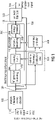
- Fig. 1 illustrates an apparatus for generating a frequency enhanced signal 140 in a preferred implementation, in which the technologies of shaping, temporal smoothing and energy limitation are performed all together.
- these technologies can also be individually applied as discussed in the context of Figs. 5 to 7 for the shaping technology, Figs. 8 to 10 for the smoothing technology and Figs. 11 to 13 for the energy limitation technology.
- the apparatus for generating the frequency enhanced signal 140 of Fig. 1 comprises an analysis filterbank or a core decoder 100 or any other device for providing the core signal in the filterbank domain such as in a QMF domain, when the core decoder outputs QMF subband signals.
- the analysis filterbank 100 can be a QMF filterbank or another analysis filterbank, when the core signal is a time domain signal or is provided in any other domain than a spectral or subband domain.
- the individual subband signals of the core signal 110 which are available at 120 are then input into a signal generator 200 and the output of the signal generator 200 is an enhancement signal 130.
- This enhancement signal 130 comprises an enhancement frequency range which is not included in the core signal 110 and the signal generator generates this enhancement signal not e.g. by (only) shaping noise or so, but using the core signal 110 or preferably the core signal subbands 120.
- the synthesis filterbank then combines the core signal subbands 120 and the frequency enhancement signal 130, and the synthesis filterbank 300 then outputs the frequency enhanced signal.
- the signal generator 200 comprises a signal generation block 202 which is indicated as "HF generation” where HF stands for high frequency.
- the frequency enhancement in Fig. 1 is not limited to the technology that a high frequency is generated. Instead, also a low frequency or an intermediate frequency can be generated and there can even be a regeneration of a spectral hole in the core signal, i.e. when the core signal has a higher band and a lower band and when there is a missing intermediate band, as is for example known from intelligent gap filling (IGF).
- the signal generation 202 may comprise copy-up procedures as known from HE-AAC or mirroring procedures, i.e. where, in order to generate the high frequency range or frequency enhancement range, the core signal is mirrored rather than copied up.
- the signal generator comprises a shaping functionality 204, which is controlled by the calculation for calculating a value indicating the energy distribution with respect to frequency in the core signal 120.
- This shaping may be a shaping of the signal generated by block 202 or alternatively the shaping of the low frequency, when the order between functionality 202 and 204 is reversed as discussed in the context of Fig. 2a to Fig. 2c .
- a further functionality is the temporal smoothing functionality 206, which is controlled by a smoothing controller 800.
- An energy limitation 208 is preferably performed at the end of the procedure, but the energy limitation can also be placed at any other position in the chain of processing functionalities 202 to 208 as long as it is made sure that the combined signal output by the synthesis filterbank 300 fulfills the energy limitation criterion such as that a higher frequency band must not have more energy than the adjacent lower frequency band or that the higher frequency band must not have more energy compared to the adjacent lower frequency band, where the increment is limited, at the most, to a predefined threshold such as 3dB
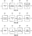
- Fig. 2a illustrates a different order, in which the shaping 204 is performed together with the temporal smoothing 206 and the energy limitation 208 before performing the HF generation 202.
- the core signal is shaped/smoothed/limited and then the already completed shaped/smoothed/limited signal is copied-up or mirrored into the enhancement frequency range.
- the order of blocks 204, 206, 208 can be performed in any way as can also be seen when Fig. 2a is compared to the order of the corresponding blocks in Fig. 1 .
- Fig. 2b illustrates a situation, in which the temporal smoothing and the shaping is performed on the low frequency or core signal, and the HF generation 202 is then performed before the energy limitation 208.
- Fig. 2c illustrates a situation where the shaping of the signal is performed to the low frequency signal and a subsequent HF generation such as by copy-up or mirroring is performed in order to obtain the signal for the enhancement frequency range, and this signal is then smoothed 206 and energy-limited 208.
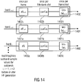
- the functionalities of shaping, temporal smoothing and energy limiting may all be performed by applying certain factors to a subband signal as, for example, illustrated in Fig. 14 .
- the shaping is implemented by multipliers 1402a, 1401a and 1400a for individual bands i, i + 1, i + 2.
- the temporal smoothing is performed by multipliers 1402b, 1401b and 1400b.
- the energy limitation is performed by limitation factors 1402c, 1401c and 1400c for the individual bands i + 2, i + 1 and i. Due to the fact that all of these functionalities are implemented in this embodiment by multiplication factors, it is to be noted that all these functionalities can also be applied to the individual subband signals by a single multiplication factor 1402, 1401, 1400 for each individual band, and this single "master" multiplication factor would then be a product of the individual factors 1402a, 1402b and 1402c for a band i + 2, and the situation would be analogous to the other bands i + 1 and i.
- the real/imaginary subband samples values for the subbands are then multiplied by this single "master" multiplication factor and the output is obtained as multiplied real/imaginary subband sample values at the output of block 1402, 1401 or 1400, which are then introduced into the synthesis filterbank 300 of Fig. 1 .
- the output of blocks 1400, 1401, 1402 corresponds to the enhancement signal 1300 typically covering the enhancement frequency range not included in the core signal.
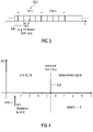
- Fig. 3 illustrates a chart indicating different time resolutions used in the process of signal generation.
- the signal is processed frame-wise.
- the analysis filterbank 100 is preferably implemented to generate time-subsequent frames 320 of subband signals, where each frame 320 of subband signals comprises a one or a plurality of slots or filterbank slots 340.
- Fig. 3 illustrates four slots per frame, there can also be 2, 3 or even more than four slots per frame.
- the shaping of the enhancement signal or the core signal based on the energy distribution of the core signal is performed once per frame.
- the temporal smoothing is performed with a high time resolution, i.e. preferably once per slot 340 and the energy limitation can once again be performed once per frame when a low complexity is required, or once per slot when a higher complexity is non-problematic for the specific implementation.
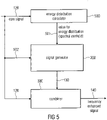
- Fig. 4 illustrates a representation of a spectrum having five subbands 1, 2, 3, 4, 5 in the core signal frequency range. Furthermore, the example in Fig. 4 has four subband signals or subbands 6, 7, 8, 9 in the enhancement signal range and the core signal range and the enhancement signal range are separated by a crossover frequency 420. Furthermore, a start frequency band 410 is illustrated, which is used for calculating the value describing an energy distribution with respect to frequency for the purpose of shaping 204, as will be discussed later on. This procedure makes sure that the lowest or a plurality of lowest subbands are not used for the calculation of the value describing the energy distribution with respect to frequency in order to obtain a better enhancement signal adjustment.
- the mirrored patch preferably consists of the negative complex conjugate of the base band in order to minimize subband aliasing in the transition region:
- Qr(t, f) is the real value of the QMF at time-index t and subband-index f and Qi ( t, f ) is the imaginary value; xover is the QMF subband referring to the crossover frequency; nBands is the integer number of bands to be extrapolated.
- the minus sign in the real part denotes the negative conjugate complex operation.
- the HF generation 202 or generally the generation of the enhancement frequency range relies on a subband representation provided by block 100.
- the inventive apparatus for generating a frequency enhanced signal should be a multi-bandwidth decoder which is able to resample the decoded signal 110 to vary sampling frequencies, to support, for example narrow band, wideband and super-wideband output. Therefore, the QMF filterbank 100 takes the decoded time domain signal as input. By padding zeroes in the frequency domain, the QMF filterbank can be used to resample the decoded signal, and the same QMF filterbank is preferably also used to create the high band signal.
- the apparatus for generating a frequency enhanced signal is operative to perform all operations in the frequency domain.
- an existing system already having an internal frequency domain representation at a decoder side is extended as illustrated in Fig. 1 by indicating block 100 as a "core decoder" which provides, for example, already a QMF filterbank domain output signal.
- This representation is simply re-used for additional tasks like sampling rate conversion and other signal manipulations which are preferably done in the frequency domain (e.g. insertion of shaped comfort noise, high-pass/low-pass filtering). Thus, no additional time-frequency transformation needs to be calculated.
- the high-band signal is generated based on the low-band signal only in this embodiment. This can be done by means of a copy-up or folding-up (mirroring) operation in the frequency domain.
- a high band signal with the same harmonic and temporal fine-structure as the low band signal is assured. This avoids a computationally costly folding of the time-domain signal and additional delay.
- the functionality of the shaping 204 technology of Fig. 1 is discussed in the context of Figs. 5 , 6 , and 7 , where the shaping can be performed in the context of Fig. 1 , 2a-2c or separately and individually together with other functionalities known from other guided or non-guided frequency enhancement technologies.
- Fig. 5 illustrates an apparatus for generating a frequency enhanced signal 140 comprising a calculator 500 for calculating a value describing an energy distribution with respect to frequency in a core signal 120.
- the signal generator 200 is configured for generating an enhancement signal comprising an enhancement frequency range not included in the core signal from the core signal as illustrated by line 502.
- the signal generator 200 is configured for shaping the enhancement signal such as output by block 202 in Fig. 1 or the core signal 120 in the context of Fig. 2a so that a spectral envelope of the enhancement signal depends on the value describing the energy distribution.
- the apparatus additionally comprises a combiner 300 for combining the enhancement signal 130 output by block 200 and the core signal 120 to obtain the frequency enhanced signal 140. Additional operations such as temporal smoothing 206 or energy limitation 208 are preferred to further process the shaped signal, but are not necessarily required in certain implementations.
- the signal generator 200 is configured to shape the enhancement signal so that a first spectral envelope decrease from a first frequency in the enhancement frequency range to a second higher frequency in the enhancement frequency range is obtained for a first value describing the energy distribution. Furthermore, a second spectral envelope decrease from the first frequency in the enhancement range to the second frequency in the enhancement range is obtained for a second value describing a second energy distribution. If the second frequency is greater than the first frequency, and the second spectral envelope decrease is greater than the first spectral envelope decrease, then the first value indicates that the core signal has an energy concentration at a higher frequency range of the core signal compared to the second value describing an energy concentration at a lower frequency range of the core signal.
- the calculator 500 is configured to calculate a measure for a spectral centroid of a current frame as the information value on the energy distribution. Then, the signal generator 200 shapes in accordance with this measure for the spectral centroid so that a spectral centroid at a higher frequency results in a more shallow slope of the spectral envelope compared to a spectral centroid at a lower frequency.
- the information on the energy distribution calculated by the energy distribution calculator 500 is calculated on a frequency portion of the core signal starting at the first frequency and ending at the second frequency being higher than the first frequency.
- the first frequency is lower than a lowest frequency in the core signal, as for example illustrated at 410 in Fig. 4 .
- the second frequency is the crossover frequency 420 but can also be a frequency lower than the crossover frequency 420 as the case may be.
- extending the second frequency used for calculating the measure for the spectral distribution as much as possible to the crossover frequency 420 is preferred and results in the best audio quality.
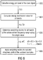
- the procedure of Fig. 6 is applied by the energy distribution calculator 500 and the signal generator 200.
- an energy value for each band of the core signal indicated at E(i) is calculated.
- a single energy distribution value such as sp used for the adjustment of all bands of the enhancement frequency range is calculated in block 604.
- weighting factors are calculated for all bands of the enhancement frequency range using for this a single value, where the weighting factors are preferably att f .
- step 608 performed by the signal generator 208, the weighting factors are applied to real and imaginary parts of the subband samples.
- Fricative sounds are detected by calculating the spectral centroid of the current frame in the QMF domain.
- the spectral centroid is a measure that has a range of 0.0 to 1.0.
- a high spectral centroid (a value close to one) means that the spectral envelope of the sound has a rising slope. For speech signals this means that the current frame most likely contains a fricative.
- E(i) is the energy of QMF subband i
- start is the QMF subband-index referring to 1 kHz.
- the value a i should be so that the value is higher for higher i and, importantly, the values b i are lower than the values a i at least for the index i > 1.
- ai bi are monotonically increasing or decreasing values with i.
- Fig. 7 illustrates individual weighting factors att f for different energy distribution values sp.
- sp is equal to 1
- the whole energy of the core signal is concentrated at the highest band the core signal.
- att is equal to 1
- the weighting factors att f are constant over frequency as illustrated at 700.
- sp is equal to 0
- att is equal to 0.5 and the corresponding course of the adjustment factors over frequency illustrated at 706.
- Courses of shaping factors over frequency indicated at 702 and 704 are for correspondingly increasing spectral distribution values.
- the energy distribution value is greater than 0 but smaller than the energy distribution value for item 702 as indicated by parametric arrow 708.
- Fig. 8 illustrates an apparatus for generating a frequency enhanced signal using the temporal smoothing technology.
- the apparatus comprises a signal generator 200 for generating an enhancement signal from a core signal 120, 110, where the enhancement signal comprises an enhancement frequency range not included in the core signal.
- a current time portion such as a frame 320 and preferably a slot 340 of the enhancement signal or the core signal comprises subband signals for a plurality of subbands.
- a controller 800 is for calculating the same smoothing information 802 for the plurality of subband signals of the enhancement frequency range or the core signal.
- the signal generator 200 is configured for smoothing the plurality of subband signals of the enhancement frequency range using the same smoothing information 802 or for smoothing the plurality of subband signals of the core signal using the same smoothing information 802.
- the output of the signal generator 200 is, in Fig. 8 , a smooth enhancement signal which can then be input into a combiner 300.
- the smoothing 206 can be performed at any place in the processing chain of Fig. 1 or can even be performed individually in the context of any other frequency enhancement scheme.
- the controller 800 is preferably configured to calculate the smoothing information using a combined energy of the plurality of subband signals the core signal and the frequency enhancement signal or using only the frequency enhancement signal of the time portion. Furthermore, an average energy of the plurality of subband signals of the core signal and the frequency enhancement signal or of the core signal only of one or more earlier time portions preceding the current time portion is used.
- the smoothing information is a single correction factor for the plurality of subband signals of the enhancement frequency range in all bands and therefore the signal generator 200 is configured to apply the correction factor to the plurality of subband signals of the enhancement frequency range.
- the apparatus furthermore comprises a filterbank 100 or a provider for providing the plurality of subband signals of the core signal for a plurality of time-subsequent filterbank slots.
- the signal generator is configured to derive the plurality of subband signals of the enhancement frequency range for the plurality of time-subsequent filterbank slots using the plurality of subband signals of the core signal and the controller 800 is configured to calculate an individual smoothing information 802 for each filterbank slot and the smoothing is then performed, for each filterbank slot, with a new individual smoothing information.
- the controller 800 is configured to calculate a smoothing intensity control value based on the core signal or the frequency enhanced signal of the current time portion and based on one or more preceding time portions and the controller 800 is then configured to calculate the smoothing information using the smoothing control value such that the smoothing intensity varies depending on a difference between an energy of the core signal or the frequency enhancement signal of the current time portion and the average energy of the core signal or the frequency enhancement signal of the one or more preceding time portions.
- Step 900 which is performed by the controller 800, comprises finding a decision about smoothing intensity which may, for example, be found based on a difference between the energy in the current time portion and an average energy in one or more preceding time portions, but any other procedures for deciding about the smoothing intensity can be used as well.
- One alternative is to used, instead or in addition future time slots.
- a further alternative is that one only has a single transform per frame and one would then smooth over timely subsequent frames. Both these alternatives, however, can introduce a delay. This can be non-problematic in applications, where delay is not a problem, such as streaming application. For applications, where a delay is problematic such as for a two way communication e.g. using mobile phones, the past or preceding frames are preferred over future frames, since the usage of the past frames does not introduce a delay.
- step 902 a smoothing information is calculated based on the decision of the smoothing intensity of the step 900.
- This step 902 is also performed by the controller 800.
- the signal generator 200 performs 904 comprising the application of the smoothing information to several bands, where one and the same smoothing information 802 is applied to these several bands either in the core signal or in the enhancement frequency range.
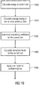
- Fig. 10 illustrates a preferred procedure of the implementation of the Fig. 9 sequence of steps.
- step 1000 an energy of a current slot is calculated.
- step 1020 an average energy of one or more previous slots is calculated.
- step 1040 a smoothing coefficient for the current slot is determined based on the difference between the values obtained by block 1000 and 1020.
- step 1060 comprises the calculation of a correction factor for the current slot and the steps 1000 to 1060 are all performed by the controller 800.
- step 1080 which is performed by the signal generator 200, the actual smoothing operation is performed, i.e. the corresponding correction factor is applied to all subband signals within one slot.
- the temporal smoothing is performed in two steps: Decision about smoothing intensity.
- the decision about the smoothing intensity the stationary of the signal over time is evaluated.
- a possible way to perform this evaluation is to compare the energy of the current short-term window or QMF time-slot with averaged energy values of previous short-term windows or QMF time-slots. To save on complexity, this might be evaluated for the high-band portion only. The closer the compared energy values are, the lower should be the intensity of smoothing. This is reflected in a smoothing coefficient ⁇ , where 0 ⁇ ⁇ ⁇ 1. The greater ⁇ , the higher is the intensity of smoothing.
- Ecurr ⁇ t a Ecurr t + 1 ⁇ a Eavg t
- the factor a may be fixed or dependent on the difference of the energy of Ecurr and Eavg.
- the time resolution for the temporal smoothing is set to be higher than the time resolution of the shaping or the time resolution of the energy limitation technology. This makes sure that a temporally smooth course of the subband signals is obtained while, at the same time, the computationally more intensive shaping is to be performed only once per frame. However, any smoothing from one subband to the other subband, i.e. in the frequency direction, is not performed, since, as has been found, this substantially reduces the subjective listening quality.
- the same smoothing information such as the correction factor for all subbands in the enhancement range.
- the same smoothing information is applied not for all bands but for a group of bands wherein such a group has at least two subbands.
- Fig. 11 illustrates a further aspect directed to the energy limitation technology 208 illustrated in Fig. 1 .
- Fig. 11 illustrates an apparatus for generating a frequency enhanced signal comprising the signal generator 200 for generating an enhancement signal, the enhancement signal comprising an enhancement frequency range not included in the core signal.
- a time portion of the enhancement signal comprises subband signals for a plurality of subbands.
- the apparatus comprises a synthesis filterbank 300 for generating the frequency enhanced signal 140 using the enhancement signal 130.
- the signal generator 200 is configured for performing an energy limitation in order to make sure that the frequency enhanced signal 140 obtained by the synthesis filterbank 300 is so that an energy of a higher band is, at the most, equal to an energy in a lower band or greater than the energy in a lower band, at the most, by a predefined threshold.
- the signal generator is preferable implemented to make sure that a higher QMF subband k must not exceed the energy at a QMF subband k - 1. Nevertheless, the signal generator 200 can also be implemented to allow a certain incremental increase which can preferably be a threshold of 3dB and a threshold can preferably be 2dB and even more preferably 1dB or even smaller.
- the predetermined threshold may be a constant for each band or dependent on the spectral centroid calculated previously. A preferred dependence is that the threshold becomes lower, when the centroid approaches lower frequencies, i.e. becomes smaller, while the threshold can become greater the closer the centroid approaches higher frequencies or sp approaches 1.
- the signal generator 200 is configured to examine a first subband signal in a first subband and to examine a subband signal in a second subband being adjacent in frequency to the first subband and having a center frequency being higher than a center frequency of the first subband and the signal generator will not limit the second subband signal, when an energy of the second subband signal is equal to an energy of the first subband signal or when the energy of the second subband signal is greater than the energy of the first subband signal by less than the predefined threshold.
- the signal generator is configured to form a plurality of processing operations in a sequence as illustrated, for example, in Fig. 1 or Figs. 2a-2c . Then, the signal generator preferably performs the energy limitation at an end of the sequence to obtain the enhancement signal 130 input into the synthesis filterbank 300.
- the synthesis filterbank 300 is configured to receive, as an input, the enhancement signal 130 generated at the end of the sequence by the final process of the energy limitation.
- the signal generator is configured to perform spectral shaping 204 or temporal smoothing 206 before the energy limitation.
- the signal generator 200 is configured to generate the plurality of subband signals of the enhancement signal by mirroring a plurality of subbands of the core signal.
- the procedure of negating either the real part or the imaginary part is performed as discussed earlier.
- the signal generator is configured for calculating a correction factor limFac and this limitation factor limFac is then applied to the subband signals of the core or the enhancement frequency range as follows:
- E f be the energy of one band averaged over a time span stop - start:
- the factor or predetermined threshold fac may be a constant for each band or dependent on the spectral centroid calculated previously.
- Q ⁇ r t,f is the energy limited real part of subband signal at the subband indicated by f .
- Q ⁇ i t,f is the corresponding imaginary part of a subband signal subsequent to energy limitation in a subband f.
- Qr t,f and Qi t,f are corresponding real and imaginary parts of the subband signals before energy limitation such as the subband signals directly when any shaping or temporal smoothing is not performed or the shaped and temporally smoothed subband signals.
- E lim is the limitation energy, which is typically the energy of the lower band or the energy of the lower band incremented by the certain threshold fac.
- E f ( j ) is the energy of the current band f or i.
- Figs. 12a and 12b illustrating a certain example where there are seven bands in the enhancement frequency range.
- Band 1202 is greater than band 1201 with respect to energy.
- band 1202 is energy-limited as indicated at 1250 in Fig. 12b for this band.
- bands 1205, 1204 and 1206 are all greater than band 1203.
- all three bands are energy-limited as illustrated as 1250 in Fig. 12b .
- the only non-limited bands that remain are bands 1201 (this is the first band in the reconstruction range) and bands 1203 and 1207.
- Fig. 12a/12b illustrates the situation where the limitation is so that a higher band must not have more energy than a lower band. However, the situation would look a bit different if a certain increment would have been allowed.
- the energy limitation may apply for a single extension band. Then, the comparison or energy limitation is done using the energy of the highest core band. This may also apply for a plurality of extension bands. Then a lowest extension band is energy limited using the highest core band, and a highest extension band is energy limited with respect to the second to highest extension band.
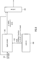
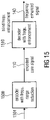
- Fig. 15 illustrates a transmission system or, generally, a system comprising an encoder 1500 and a decoder 1510.
- the encoder is preferably an encoder for generating the encoded core signal which performs a bandwidth reduction, or generally which deletes several frequency ranges in the original audio signal 1501, which do not necessarily have to be a complete upper frequency range or upper band, but which can also be any frequency band in between core frequency bands.
- the encoded core signal is transmitted from the encoder 1500 to the decoder 1510 without any side information and the decoder 1510 then performs a non-guided frequency enhancement to obtain the frequency enhancement signal 140.
- the decoder can be implemented as discussed in any of the Figs. 1 to 14 .
- the present invention has been illustrated in the context of block diagrams where the blocks represent actual or logical hardware components, the present invention can also be implemented by a computer-implemented method. In the latter case, the blocks represent corresponding method steps where these steps stand for the functionalities performed by corresponding logical or physical hardware blocks.
- aspects have been described in the context of an apparatus, it is clear that these aspects also represent a description of the corresponding method, where a block or device corresponds to a method step or a feature of a method step. Analogously, aspects described in the context of a method step also represent a description of a corresponding block or item or feature of a corresponding apparatus.
- Some or all of the method steps may be executed by (or using) a hardware apparatus, like for example, a microprocessor, a programmable computer or an electronic circuit. In some embodiments, some one or more of the most important method steps may be executed by such an apparatus.
- the transmitted or encoded signal can be stored on a digital storage medium or can be transmitted on a transmission medium such as a wireless transmission medium or a wired transmission medium such as the Internet.
- embodiments of the invention can be implemented in hardware or in software.
- the implementation can be performed using a digital storage medium, for example a floppy disc, a DVD, a Blu-Ray, a CD, a ROM, a PROM, and EPROM, an EEPROM or a FLASH memory, having electronically readable control signals stored thereon, which cooperate (or are capable of cooperating) with a programmable computer system such that the respective method is performed. Therefore, the digital storage medium may be computer readable.
- Some exemplary implementations comprise a data carrier having electronically readable control signals, which are capable of cooperating with a programmable computer system, such that one of the methods described herein is performed.
- embodiments of the present invention can be implemented as a computer program product with a program code, the program code being operative for performing one of the methods when the computer program product runs on a computer.
- the program code may, for example, be stored on a machine readable carrier.
- exemplary implementations comprise the computer program for performing one of the methods described herein, stored on a machine readable carrier.
- an exemplary implementation is, therefor, a computer program having a program code for performing one of the methods described herein, when the computer program runs on a computer.
- a further exemplary implementation is, therefor, a data carrier (or a non-transitory storage medium such as a digital storage medium, or a computer-readable medium) comprising, recorded thereon, the computer program for performing one of the methods described herein.
- the data carrier, the digital storage medium or the recorded medium are typically tangible and/or non-transitory.
- a further exemplary implementation is, therefor, a data stream or a sequence of signals representing the computer program for performing one of the methods described herein.
- the data stream or the sequence of signals may, for example, be configured to be transferred via a data communication connection, for example, via the internet.
- a further exemplary implementation comprises a processing means, for example, a computer or a programmable logic device, configured to, or adapted to, perform one of the methods described herein.
- a processing means for example, a computer or a programmable logic device, configured to, or adapted to, perform one of the methods described herein.
- a further exemplary implementation comprises a computer having installed thereon the computer program for performing one of the methods described herein.
- a further exemplary implementation comprises an apparatus or a system configured to transfer (for example, electronically or optically) a computer program for performing one of the methods described herein to a receiver.
- the receiver may, for example, be a computer, a mobile device, a memory device or the like.
- the apparatus or system may, for example, comprise a file server for transferring the computer program to the receiver.
- a programmable logic device for example, a field programmable gate array
- a field programmable gate array may cooperate with a microprocessor in order to perform one of the methods described herein.
- the methods are preferably performed by any hardware apparatus.
Description
- The present invention is related to an apparatus or method for generating a frequency enhancement audio signal.
- Embodiments are based on audio coding and in particular on frequency enhancement procedures such as bandwidth extension, spectral band replication or intelligent gap filling. Embodiments are also particularly related to non-guided frequency enhancement procedures, i.e. where the decoder-side operates without side information or only with a minimum amount of side information.
- Perceptual audio codecs often quantize and code only a lowpass part of the whole perceivable frequency range of an audio signal, especially when operated at (relatively) low bitrates. Although this approach guarantees an acceptable quality for the coded low-frequency signal, most listeners perceive the missing of the highpass part as a quality degradation. To overcome this issue, the missing high-frequency part can by synthesized by bandwidth extension schemes.
- State of the art codecs often use either a waveform-preserving coder, such as AAC, or a parametric coder, such as a speech coder, to code the low-frequency signal. These coders operate up to a certain stop frequency. This frequency is called crossover frequency. The frequency portion below the crossover frequency is called low band. The signal above the crossover frequency, which is synthesized by means of a bandwidth extension scheme, is called high band.
- A bandwidth extension typically synthesizes the missing bandwidth (high band) by means of the transmitted signal (low band) and extra side information. If applied in the field of low-bitrate audio coding, the extra information should consume as little as possible extra bitrate. Thus, usually a parametric representation is chosen for the extra information. This parametric representation is either transmitted from the encoder at comparably low bitrate (guided bandwidth extension) or estimated at the decoder based on specific signal characteristics (non-guided bandwidth extension). In the latter case, the parameters consume no bitrate at all.
- The synthesis of the high band typically consists of two parts:
- 1. Generation of the high-frequency content. This can be done by either copying or flipping (parts of) the low frequency content to the high band, or inserting white or shaped noise or other artificial signal portions into the high band.
- 2. Adjustment of the generated high frequency content according to the parametric information. This includes manipulation of shape, tonality/noisiness and energy according to the parametric representation.
- The goal of the synthesis process is usually to achieve a signal that is perceptually close to the original signal. If this goal can't be matched, the synthesized portion should be least disturbing for the listener.
- Other than a guided BWE scheme, a non-guided bandwidth extension can't rely on extra information for the synthesis of the high band. Instead, it typically uses empirical rules to exploit correlation between low band and high band. Whereas most music pieces and voiced speech segments exhibit a high correlation between high and low frequency band, this is usually not the case for unvoiced or fricative speech segments. Fricative sounds have very few energy in the lower frequency range while having high energy above a certain frequency. If this frequency is close to the crossover frequency, then it can be problematic to generate the artificial signal above the crossover frequency since in that case the lowband does contain little relevant signal parts. To cope with this problem, a good detection of such sounds is helpful.
- HE-AAC is a well-known codec that consists of a waveform preserving codec for the low band (AAC) and a parametric codec for the high band (SBR). At decoder side, the high band signal is generated by transforming the decoded AAC signal into the frequency domain using a QMF filterbank. Subsequently, subbands of the low band signal are copied to the high band (generation of high frequency content). This high band signal is then adjusted in spectral envelope, tonality and noise floor based on the transmitted parametric side-information (adjustment of the generated high frequency content). Since this method uses a guided BWE approach, a weak correlation between high and low band is in general not problematic and can be overcome be transmitting the appropriate parameter sets. However, this requires additional bitrate, which might not be acceptable for a given application scenario.
- The ITU Standard G.722.2 is a speech codec that operates in time domain only, i.e. without performing any calculations in frequency domain. Such a decoder outputs a time domain signal with a sampling rate of 12.8 kHz, which is subsequently upsampled to 16 kHz. The generation of the high frequency content (6.4 - 7.0 kHz) is based on inserting bandpass noise. In most operation modes the spectral shaping of the noise is done without using any side-information, only in the operation mode with highest bitrate information about the noise energy is transmitted in the bitstream. For reasons of simplicity, and since not all application scenarios can afford the transmission of extra parameters sets, in the following only the generation of the high band signal without using any side-information is described.
- For generating the high band signal, a noise signal is scaled to have the same energy as the core excitation signal. In order to give more energy to unvoiced parts of the signal, a spectral tilt e is calculated:

- The non-guided bandwidth extension from G.722.2, which entirely operates in time domain, has the following drawbacks:
- 1. The generated HF content is based on noise. This creates audible artifacts if the HF signal is combined with a tonal, harmonic low-frequency signal (e.g. music). To avoid such artifacts, G.722.2 strongly limits the energy of the generated HF signal, which also limits potential benefits of the bandwidth extension. Thus, unfortunately also the maximum possible improvement of the brightness of a sound or the maximum obtainable increase in intelligibility of a speech signal is limited.
- 2. Since this non-guided bandwidth extension operates in the time domain, the filter operations cause additional algorithmic delay. This additional delay lowers the quality of the user experience in bi-directional communication scenarios or might not be allowed by the terms of requirement of a given communication technology standard.
- 3. Also, since the signal processing is performed in time domain, the filter operations are prone to instabilities. Moreover, the time domain filters have a high computational complexity.
- 4. Since only the overall sum of the energy of the high band signal is adapted to the energy of the core signal (and further weighted by the spectral tilt), there might be a significant local mismatch of energy at the crossover frequency between upper frequency range of the core signal (the signal just below the crossover frequency) and the high band signal. For example, this will be the case especially for tonal signals that exhibit an energy concentration in the very low frequency range but contain little energy in the upper frequency range.
- 5. Furthermore, it is computationally complex to estimate a spectral slope in a time domain representation. In frequency domain, an extrapolation of a spectral slope can be done very efficiently. Since most of the energy of e.g. fricatives is concentrated in the high frequency range, these may sound dull if a conservative energy and spectral slope estimation strategy like in G.722.2 is applied (see 1.).
- To summarize, the prior art non-guided or blind bandwidth extension schemes may require a significant computational complexity on the decoder side and nevertheless result in a limited audio quality specifically for problematic speech sounds such as fricatives. Furthermore, guided bandwidth extension schemes, although providing a better audio quality and sometimes requiring less computational complexity on the decoder side cannot provide the substantial bitrate reductions due to the fact that the additional parametric information on the high band can require a significant amount of additional bitrate with respect to the encoded core audio signal.
-
WO 2012017621 A1 discloses a method, system, and computer program product for processing an encoded audio signal. The system receives an encoded low-frequency range signal and encoded energy information used to frequency shift the encoded low-frequency range signal. The low-frequency range signal is decoded and an energy depression of the decoded signal is smoothed. The smoothed low-frequency range signal is frequency shifted to generate a high-frequency range signal. The low-frequency range signal and high-frequency range signal are then combined and outputted. - "Digital cellular telecommunications system ( describes the AMR-WB+ codec.
-
WO 2011110031 A1 discloses a method and device for encoding a high frequency signal, and a method and device for decoding a high frequency signal are provided The method for encoding a high frequency signal includes: determining the signal class of a high frequency signal of a current frame; smoothing and scaling the time envelopes of the high frequency signal of the current frame and obtaining the time envelopes of the high frequency signal of the current frame that require to be encoded, if the high frequency signal of the current frame is a NON-TRANSIENT signal and the high frequency signal of the previous frame is a TRANSIENT signal; quantizing and encoding the time envelopes of the high frequency signal of the current frame that require to be encoded, and the frequency information and the signal class information of the high frequency signal of the current frame. The signal class information of the TRANSIENT signal is used when the signal class information of the high frequency signal of the current frame is quantized and encoded. Therefore, the performance of the TRANSIENT signal is improved, and the deviation of the characteristics of a restored high frequency signal from the characteristics of an actual high frequency signal is reduced. -
EP 2 019 391 A2 discloses an audio decoding apparatus, an audio decoding method, and an audio decoding program which employ a band expansion technique, wherein the audio decoding apparatus comprises: a bit stream separator for separating a bit stream into a low-frequency bit stream and a high-frequency bit stream; a low-frequency decoder for decoding the low-frequency bit stream to generates a low-frequency audio signal; a subband divider for dividing the low-frequency audio signal into a plurality of complex-valued signals in respective frequency bands to generate low-frequency subband signals; a corrective coefficient extractor for calculating an energy corrective coefficient based on the low-frequency subband signals; an energy corrector for correcting a target energy described by the high-frequency bit stream with the energy corrective coefficient to calculate a corrected target energy; a band expander for generating a high-frequency subband signal by correcting, in amplitude, the signal energy of a signal which is generated by copying and processing the low-frequency subband signals as instructed by the high-frequency bit stream, at the corrected target energy; and a subband combiner for combining the bands of the low-frequency subband signals and a real part of the high-frequency subband signal with each other with a subband combining filter to produce a decoded audio signal. -
US 2010/217606 A1 discloses a signal bandwidth expanding apparatus configured to expand a bandwidth of an input signal, the apparatus including: a time acquiring section configured to acquire time information; a priority holding section configured to hold priority information of processes, each process divided from a process of bandwidth expansion; a controller configured to: sequentially perform the processes from a process having a higher priority using the priority information held by the priority holding section, calculate a time taken for the process using the time acquiring section when the process is ended, and control whether or not a next process having a secondary priority is performed according to the time taken for the process; and a frequency balance correcting section configured to change a frequency characteristic of a signal expanded in a bandwidth according to the process performed by the controller. - It is an object of the present invention to provide an improved concept for audio processing in the context of non-guided frequency enhancement technologies.
- This object is achieved by an apparatus for generating a frequency enhancement audio signal, as set forth in
claim 1, a method of generating a frequency enhancement audio signal, as set forth in claim 12, a system comprising an encoder and an apparatus for generating a frequency enhancement audio signal, as set forth in claim 13, a method corresponding to the system of claim 13, as set forth in claim 14, or a computer program, as set forth in claim 15. - The present invention provides a frequency enhancement scheme such as a bandwidth extension scheme for audio codecs. This scheme aims at extending the frequency bandwidth of an audio codec without the need of extra side-information or with only a minimum amount significantly reduced compared to a full parametric description of missing bands as in guided bandwidth extension schemes.
- An apparatus for generating a frequency enhanced signal in accordance with an example comprises a calculator for calculating a value describing an energy distribution with respect to frequency in a core signal. A signal generator for generating an enhancement signal comprising an enhancement frequency range not included in the core signal operates using the core signal and then performs a shaping of the enhancement signal or the core signal so that the spectral envelope of the enhancement signal depends on the value describing the energy distribution.
- Thus, the envelope of the enhancement signal, or the enhancement signal is shaped based on this value describing the energy distribution. This value can be easily calculated and this value then defines the full envelope shape or the full shape of the enhancement signal. Thus, the decoder can operate with a low complexity and at the same time a good audio quality is obtained. Specifically, the energy distribution in the core signal when used for the spectral shaping of the frequency enhancement signal results in a good audio quality even though the processing of calculating the value on the energy distribution such as a spectral centroid in the core signal and the adjustment of the enhancement signal based on this spectral centroid is a procedure which is straightforward and can be performed with low computational resources.
- Furthermore, this procedure allows that the absolute energy and the slope (roll-off) of the high band signal are derived from the absolute energy and the slope (roll-off) of the core signal, respectively. It is preferred to perform these operations in the frequency domain so that they can be done in the computationally efficient way, since the shaping of a spectral envelope is equivalent to simply multiplying the frequency representation with a gain curve, and this gain curve is derived from the value describing the energy distribution with respect to frequency in the core signal.
- Furthermore it is computationally complex to precisely estimate and extrapolate a given spectral shape in the time domain. Thus, such operations are preferably performed in the frequency domain. Fricative sounds for example have typically only a low amount of energy at low frequencies and a high amount of energy at high frequencies. The rise in energy is dependent on the actual fricative sound and might start only little below the crossover frequency. In the time domain, it is difficult to detect this situation and computationally complex to obtain a valid extrapolation from it. For non-fricative sounds it is assured that the energy of the artificial generated spectrum always drops with rising frequency.
- In a further example, a temporal smoothing procedure is applied. A signal generator for generating an enhancement signal from a core signal is provided. A time portion of the enhancement signal or the core signal comprises subband signals for a plurality of subbands. A controller for calculating the same smoothing information for the plurality of subband signals of the enhancement frequency range is provided and this smoothing information is then used by the signal generator for smoothing the plurality of subband signals of the enhancement frequency range, particularly using the same smoothing information or, alternatively, when the smoothing is performed before the high frequency generation, then the plurality of subband signals of the core signal are smoothed all using the same smoothing information. This temporal smoothing avoids the continuation of smaller fast energy fluctuations, which are inherited from the low-band, to the high-band, and thus leads to a more pleasant perceptual impression. The low-band energy fluctuations are usually caused by quantization errors of the underlying core-coder that lead to instabilities. The smoothing is signal adaptive since it is dependent on the (long-term) stationary of the signal. Furthermore, the usage of one and the same smoothing information for all individual subbands makes sure that the coherency between the subbands is not changed by the temporal smoothing. Instead, all subbands are smoothed in the same way, and the smoothing information is derived from all subbands or from only the subbands in the enhancement frequency range. Thus, a significantly better audio quality compared to an individual smoothing of each subband signal individually is obtained.
- The invention is related to performing an energy limitation, preferably at the end of the whole procedure for generating the enhancement signal, wherein the procedure according to the invention is particularly useful for non-guided bandwidth extension schemes, but can also help in guided bandwidth extension schemes, since the non-guided bandwidth extension schemes are prone to artifacts caused by spectral components which stick out unnaturally, especially at segments which have a negative spectral tilt. These components might lead to high-frequency noise-bursts. To avoid such a situation, the energy limitation is preferably applied at the end of the processing, which limits the energy increment over frequency. In an implementation, the energy at a QMF (Quadrature Mirror Filtering) subband k must not exceed the energy at a QMF subband k-1. This energy limiting is performed on a time-slot base. Thus, it is made sure that any unnatural situations in bandwidth extension schemes are avoided, since it is very unnatural that a higher frequency band has more energy than the lower frequency band or that the energy of a higher frequency band is higher by more than the predefined threshold, such as a threshold of 3dB, than the energy in the lower band. Typically, all speech/music signals have a low-pass characteristic, i.e. have a more or less monotonically decreasing energy content over frequency. This may apply for a single extension band. Then, the comparison or energy limitation is done using the energy of the highest core band. This may also apply for a plurality of extension bands. Then a lowest extension band is energy limited using the highest core band, and a highest extension band is energy limited with respect to the second to highest extension band.
- Although the technologies of shaping of the frequency enhancement signal, temporal smoothing of the frequency enhancement subband signals and energy limitation can be performed individually and separately from each other, these procedures can also be performed all together within preferably a non-guided frequency enhancement scheme.
- Furthermore, reference is made to the dependent claims which refer to preferred embodiments of the present invention . Examples for illustrating the present invention are subsequently described with respect to the accompanying drawings, in which:
- Fig. 1
- illustrates an example comprising the technologies of shaping a frequency enhancement signal, the smoothing of the subband signal and the energy limitation;
- Fig. 2a-2c
- illustrate different implementations of the signal generator of
Fig. 1 ; - Fig. 3
- illustrates individual time portions, where a frame has a long time portion and a slot has a short time portion and each frame comprises a plurality of slots;
- Fig. 4
- illustrates a spectral chart indicating the spectral position of a core signal and an enhancement signal in an implementation of a bandwidth extension application;
- Fig. 5
- illustrates an apparatus for generating the frequency enhanced signal using a spectral shaping based on the value describing an energy distribution of the core signal;
- Fig. 6
- illustrates an implementation of the shaping technology;
- Fig. 7
- illustrates different roll-offs determined by a certain spectral centroid;
- Fig. 8
- illustrates an apparatus for generating the frequency enhanced signal comprising the same smoothing information for smoothing the subband signals of the core signal or the frequency enhancement signal;
- Fig. 9
- illustrates a preferred procedure applied by the controller and the signal generator of
Fig. 8 ; - Fig. 10
- illustrates a further procedure applied by the controller and the signal generator of
Fig. 8 ; - Fig. 11
- illustrates an apparatus for generating a frequency enhancement signal in accordance with the invention, which performs an energy limitation procedure in the enhancement signal so that a higher band of the enhancement signal may, at the most, have the same energy of the adjacent lower band or is, at the most, higher in energy by a predefined threshold;
- Fig. 12a
- illustrates the spectrum of the enhancement signal before limitation;
- Fig. 12b
- illustrates the spectrum of
Fig. 12a subsequent to the limitation; - Fig. 13
- illustrates a process performed by the signal generator in an implementation;
- Fig. 14
- illustrates the concurrent application of the technologies of shaping, smoothing and energy limitation within a filterbank domain; and
- Fig. 15
- illustrates a system comprising an encoder and a non-guided frequency enhancement decoder.
-
Fig. 1 illustrates an apparatus for generating a frequency enhancedsignal 140 in a preferred implementation, in which the technologies of shaping, temporal smoothing and energy limitation are performed all together. However, these technologies can also be individually applied as discussed in the context ofFigs. 5 to 7 for the shaping technology,Figs. 8 to 10 for the smoothing technology andFigs. 11 to 13 for the energy limitation technology. - Preferably, the apparatus for generating the frequency enhanced
signal 140 ofFig. 1 comprises an analysis filterbank or acore decoder 100 or any other device for providing the core signal in the filterbank domain such as in a QMF domain, when the core decoder outputs QMF subband signals. Alternatively, theanalysis filterbank 100 can be a QMF filterbank or another analysis filterbank, when the core signal is a time domain signal or is provided in any other domain than a spectral or subband domain. - The individual subband signals of the
core signal 110 which are available at 120 are then input into asignal generator 200 and the output of thesignal generator 200 is anenhancement signal 130. Thisenhancement signal 130 comprises an enhancement frequency range which is not included in thecore signal 110 and the signal generator generates this enhancement signal not e.g. by (only) shaping noise or so, but using thecore signal 110 or preferably thecore signal subbands 120. The synthesis filterbank then combines thecore signal subbands 120 and thefrequency enhancement signal 130, and thesynthesis filterbank 300 then outputs the frequency enhanced signal. - Basically, the
signal generator 200 comprises asignal generation block 202 which is indicated as "HF generation" where HF stands for high frequency. However, the frequency enhancement inFig. 1 is not limited to the technology that a high frequency is generated. Instead, also a low frequency or an intermediate frequency can be generated and there can even be a regeneration of a spectral hole in the core signal, i.e. when the core signal has a higher band and a lower band and when there is a missing intermediate band, as is for example known from intelligent gap filling (IGF). Thesignal generation 202 may comprise copy-up procedures as known from HE-AAC or mirroring procedures, i.e. where, in order to generate the high frequency range or frequency enhancement range, the core signal is mirrored rather than copied up. - Furthermore, the signal generator comprises a
shaping functionality 204, which is controlled by the calculation for calculating a value indicating the energy distribution with respect to frequency in thecore signal 120. This shaping may be a shaping of the signal generated byblock 202 or alternatively the shaping of the low frequency, when the order betweenfunctionality Fig. 2a to Fig. 2c . - A further functionality is the
temporal smoothing functionality 206, which is controlled by a smoothingcontroller 800. Anenergy limitation 208 is preferably performed at the end of the procedure, but the energy limitation can also be placed at any other position in the chain ofprocessing functionalities 202 to 208 as long as it is made sure that the combined signal output by thesynthesis filterbank 300 fulfills the energy limitation criterion such as that a higher frequency band must not have more energy than the adjacent lower frequency band or that the higher frequency band must not have more energy compared to the adjacent lower frequency band, where the increment is limited, at the most, to a predefined threshold such as 3dB -
Fig. 2a illustrates a different order, in which the shaping 204 is performed together with thetemporal smoothing 206 and theenergy limitation 208 before performing theHF generation 202. Thus, the core signal is shaped/smoothed/limited and then the already completed shaped/smoothed/limited signal is copied-up or mirrored into the enhancement frequency range. Furthermore, it is important to understand that the order ofblocks Fig. 2a is compared to the order of the corresponding blocks inFig. 1 . -
Fig. 2b illustrates a situation, in which the temporal smoothing and the shaping is performed on the low frequency or core signal, and theHF generation 202 is then performed before theenergy limitation 208. Furthermore,Fig. 2c illustrates a situation where the shaping of the signal is performed to the low frequency signal and a subsequent HF generation such as by copy-up or mirroring is performed in order to obtain the signal for the enhancement frequency range, and this signal is then smoothed 206 and energy-limited 208. - Furthermore, it is to be emphasized that the functionalities of shaping, temporal smoothing and energy limiting may all be performed by applying certain factors to a subband signal as, for example, illustrated in
Fig. 14 . The shaping is implemented bymultipliers - Furthermore, the temporal smoothing is performed by
multipliers limitation factors single multiplication factor individual factors block synthesis filterbank 300 ofFig. 1 . Thus, the output ofblocks -
Fig. 3 illustrates a chart indicating different time resolutions used in the process of signal generation. Basically, the signal is processed frame-wise. This means that theanalysis filterbank 100 is preferably implemented to generate time-subsequent frames 320 of subband signals, where eachframe 320 of subband signals comprises a one or a plurality of slots orfilterbank slots 340. AlthoughFig. 3 illustrates four slots per frame, there can also be 2, 3 or even more than four slots per frame. As illustrated inFig. 14 , the shaping of the enhancement signal or the core signal based on the energy distribution of the core signal is performed once per frame. On the other hand, the temporal smoothing is performed with a high time resolution, i.e. preferably once perslot 340 and the energy limitation can once again be performed once per frame when a low complexity is required, or once per slot when a higher complexity is non-problematic for the specific implementation. -
Fig. 4 illustrates a representation of a spectrum having fivesubbands Fig. 4 has four subband signals orsubbands crossover frequency 420. Furthermore, astart frequency band 410 is illustrated, which is used for calculating the value describing an energy distribution with respect to frequency for the purpose of shaping 204, as will be discussed later on. This procedure makes sure that the lowest or a plurality of lowest subbands are not used for the calculation of the value describing the energy distribution with respect to frequency in order to obtain a better enhancement signal adjustment. - Subsequently, an implementation of the
generation 202 of the enhancement frequency range not included in the core signal using the core signal is illustrated. - In order to generate the artificial signal above the crossover frequency, typically QMF values from the frequency range below the crossover frequency are copied ("patched") up into the high band. This copy-operation can be done by just shifting QMF samples from the lower frequency range up to the area above the crossover frequency or by additionally mirroring these samples. The advantage of the mirroring is that the signal just below the crossover frequency and the artificial generated signal will have a very similar energy and harmonic structure at the crossover frequency. The mirroring or copy up can be applied to a single subband of the core signal or to a plurality of subbands of the core signal.
- In the case of said QMF filterbank, the mirrored patch preferably consists of the negative complex conjugate of the base band in order to minimize subband aliasing in the transition region:


- Here, Qr(t, f) is the real value of the QMF at time-index t and subband-index f and Qi(t, f) is the imaginary value; xover is the QMF subband referring to the crossover frequency; nBands is the integer number of bands to be extrapolated. The minus sign in the real part denotes the negative conjugate complex operation.
- Preferably, the
HF generation 202 or generally the generation of the enhancement frequency range relies on a subband representation provided byblock 100. Preferably, the inventive apparatus for generating a frequency enhanced signal should be a multi-bandwidth decoder which is able to resample the decodedsignal 110 to vary sampling frequencies, to support, for example narrow band, wideband and super-wideband output. Therefore, the QMF filterbank 100 takes the decoded time domain signal as input. By padding zeroes in the frequency domain, the QMF filterbank can be used to resample the decoded signal, and the same QMF filterbank is preferably also used to create the high band signal. - Preferably, the apparatus for generating a frequency enhanced signal is operative to perform all operations in the frequency domain. Thus, an existing system already having an internal frequency domain representation at a decoder side is extended as illustrated in
Fig. 1 by indicatingblock 100 as a "core decoder" which provides, for example, already a QMF filterbank domain output signal. - This representation is simply re-used for additional tasks like sampling rate conversion and other signal manipulations which are preferably done in the frequency domain (e.g. insertion of shaped comfort noise, high-pass/low-pass filtering). Thus, no additional time-frequency transformation needs to be calculated.
- Instead of using noise for the HF content, the high-band signal is generated based on the low-band signal only in this embodiment. This can be done by means of a copy-up or folding-up (mirroring) operation in the frequency domain. Thus, a high band signal with the same harmonic and temporal fine-structure as the low band signal is assured. This avoids a computationally costly folding of the time-domain signal and additional delay.
- Subsequently, the functionality of the shaping 204 technology of
Fig. 1 is discussed in the context ofFigs. 5 ,6 , and7 , where the shaping can be performed in the context ofFig. 1 ,2a-2c or separately and individually together with other functionalities known from other guided or non-guided frequency enhancement technologies. -
Fig. 5 illustrates an apparatus for generating a frequency enhancedsignal 140 comprising acalculator 500 for calculating a value describing an energy distribution with respect to frequency in acore signal 120. Furthermore, thesignal generator 200 is configured for generating an enhancement signal comprising an enhancement frequency range not included in the core signal from the core signal as illustrated byline 502. Furthermore, thesignal generator 200 is configured for shaping the enhancement signal such as output byblock 202 inFig. 1 or thecore signal 120 in the context ofFig. 2a so that a spectral envelope of the enhancement signal depends on the value describing the energy distribution. - Preferably, the apparatus additionally comprises a
combiner 300 for combining theenhancement signal 130 output byblock 200 and thecore signal 120 to obtain the frequency enhancedsignal 140. Additional operations such as temporal smoothing 206 orenergy limitation 208 are preferred to further process the shaped signal, but are not necessarily required in certain implementations. - The
signal generator 200 is configured to shape the enhancement signal so that a first spectral envelope decrease from a first frequency in the enhancement frequency range to a second higher frequency in the enhancement frequency range is obtained for a first value describing the energy distribution. Furthermore, a second spectral envelope decrease from the first frequency in the enhancement range to the second frequency in the enhancement range is obtained for a second value describing a second energy distribution. If the second frequency is greater than the first frequency, and the second spectral envelope decrease is greater than the first spectral envelope decrease, then the first value indicates that the core signal has an energy concentration at a higher frequency range of the core signal compared to the second value describing an energy concentration at a lower frequency range of the core signal. - Preferably, the
calculator 500 is configured to calculate a measure for a spectral centroid of a current frame as the information value on the energy distribution. Then, thesignal generator 200 shapes in accordance with this measure for the spectral centroid so that a spectral centroid at a higher frequency results in a more shallow slope of the spectral envelope compared to a spectral centroid at a lower frequency. - The information on the energy distribution calculated by the
energy distribution calculator 500 is calculated on a frequency portion of the core signal starting at the first frequency and ending at the second frequency being higher than the first frequency. The first frequency is lower than a lowest frequency in the core signal, as for example illustrated at 410 inFig. 4 . Preferably, the second frequency is thecrossover frequency 420 but can also be a frequency lower than thecrossover frequency 420 as the case may be. However, extending the second frequency used for calculating the measure for the spectral distribution as much as possible to thecrossover frequency 420 is preferred and results in the best audio quality. - In an embodiment, the procedure of
Fig. 6 is applied by theenergy distribution calculator 500 and thesignal generator 200. Instep 602, an energy value for each band of the core signal indicated at E(i) is calculated. Then, a single energy distribution value such as sp used for the adjustment of all bands of the enhancement frequency range is calculated inblock 604. Then, instep 606, weighting factors are calculated for all bands of the enhancement frequency range using for this a single value, where the weighting factors are preferably attf. - Then, in
step 608 performed by thesignal generator 208, the weighting factors are applied to real and imaginary parts of the subband samples. - Fricative sounds are detected by calculating the spectral centroid of the current frame in the QMF domain. The spectral centroid is a measure that has a range of 0.0 to 1.0. A high spectral centroid (a value close to one) means that the spectral envelope of the sound has a rising slope. For speech signals this means that the current frame most likely contains a fricative. The closer the value of the spectral centroid approaches one, the steeper is the slope of the spectral envelope or the more energy is concentrated in the higher frequency range.
- The spectral centroid is calculated according to:


- Apart from the above equation, other equations having a comparable performance can be applied. Such other equations are as follows:

- In particular, the value a i should be so that the value is higher for higher i and, importantly, the values bi are lower than the values a i at least for the index i > 1. Thus, a similar result, but with a different equation compared to the above equation, is obtained. Generally, ai, bi are monotonically increasing or decreasing values with i.
- Furthermore, reference is made to
Fig. 7. Fig. 7 illustrates individual weighting factors attf for different energy distribution values sp. When sp is equal to 1, then the whole energy of the core signal is concentrated at the highest band the core signal. Then, att is equal to 1 and the weighting factors attf are constant over frequency as illustrated at 700. When, on the other hand, the complete energy in the core signal is concentrated at the lowest band of the core signal, then sp is equal to 0 and att is equal to 0.5 and the corresponding course of the adjustment factors over frequency illustrated at 706. - Courses of shaping factors over frequency indicated at 702 and 704 are for correspondingly increasing spectral distribution values. Thus, for
item 704, the energy distribution value is greater than 0 but smaller than the energy distribution value foritem 702 as indicated byparametric arrow 708. -
Fig. 8 illustrates an apparatus for generating a frequency enhanced signal using the temporal smoothing technology. The apparatus comprises asignal generator 200 for generating an enhancement signal from acore signal frame 320 and preferably aslot 340 of the enhancement signal or the core signal comprises subband signals for a plurality of subbands. - A
controller 800 is for calculating thesame smoothing information 802 for the plurality of subband signals of the enhancement frequency range or the core signal. Furthermore, thesignal generator 200 is configured for smoothing the plurality of subband signals of the enhancement frequency range using thesame smoothing information 802 or for smoothing the plurality of subband signals of the core signal using thesame smoothing information 802. The output of thesignal generator 200 is, inFig. 8 , a smooth enhancement signal which can then be input into acombiner 300. As discussed in the context ofFigs. 2a-2c , the smoothing 206 can be performed at any place in the processing chain ofFig. 1 or can even be performed individually in the context of any other frequency enhancement scheme. - The
controller 800 is preferably configured to calculate the smoothing information using a combined energy of the plurality of subband signals the core signal and the frequency enhancement signal or using only the frequency enhancement signal of the time portion. Furthermore, an average energy of the plurality of subband signals of the core signal and the frequency enhancement signal or of the core signal only of one or more earlier time portions preceding the current time portion is used. The smoothing information is a single correction factor for the plurality of subband signals of the enhancement frequency range in all bands and therefore thesignal generator 200 is configured to apply the correction factor to the plurality of subband signals of the enhancement frequency range. - As discussed in the context of
Fig. 1 , the apparatus furthermore comprises afilterbank 100 or a provider for providing the plurality of subband signals of the core signal for a plurality of time-subsequent filterbank slots. Furthermore, the signal generator is configured to derive the plurality of subband signals of the enhancement frequency range for the plurality of time-subsequent filterbank slots using the plurality of subband signals of the core signal and thecontroller 800 is configured to calculate anindividual smoothing information 802 for each filterbank slot and the smoothing is then performed, for each filterbank slot, with a new individual smoothing information. - The
controller 800 is configured to calculate a smoothing intensity control value based on the core signal or the frequency enhanced signal of the current time portion and based on one or more preceding time portions and thecontroller 800 is then configured to calculate the smoothing information using the smoothing control value such that the smoothing intensity varies depending on a difference between an energy of the core signal or the frequency enhancement signal of the current time portion and the average energy of the core signal or the frequency enhancement signal of the one or more preceding time portions. - Reference is made to
Fig. 9 illustrating a procedure performed by thecontroller 800 and thesignal generator 200.Step 900, which is performed by thecontroller 800, comprises finding a decision about smoothing intensity which may, for example, be found based on a difference between the energy in the current time portion and an average energy in one or more preceding time portions, but any other procedures for deciding about the smoothing intensity can be used as well. One alternative is to used, instead or in addition future time slots. A further alternative is that one only has a single transform per frame and one would then smooth over timely subsequent frames. Both these alternatives, however, can introduce a delay. This can be non-problematic in applications, where delay is not a problem, such as streaming application. For applications, where a delay is problematic such as for a two way communication e.g. using mobile phones, the past or preceding frames are preferred over future frames, since the usage of the past frames does not introduce a delay. - Then, in
step 902, a smoothing information is calculated based on the decision of the smoothing intensity of thestep 900. Thisstep 902 is also performed by thecontroller 800. Then, thesignal generator 200 performs 904 comprising the application of the smoothing information to several bands, where one and thesame smoothing information 802 is applied to these several bands either in the core signal or in the enhancement frequency range. -
Fig. 10 illustrates a preferred procedure of the implementation of theFig. 9 sequence of steps. Instep 1000, an energy of a current slot is calculated. Then, instep 1020, an average energy of one or more previous slots is calculated. Then, instep 1040, a smoothing coefficient for the current slot is determined based on the difference between the values obtained byblock step 1060 comprises the calculation of a correction factor for the current slot and thesteps 1000 to 1060 are all performed by thecontroller 800. Then, instep 1080, which is performed by thesignal generator 200, the actual smoothing operation is performed, i.e. the corresponding correction factor is applied to all subband signals within one slot. - In an embodiment, the temporal smoothing is performed in two steps:
Decision about smoothing intensity. For the decision about the smoothing intensity, the stationary of the signal over time is evaluated. A possible way to perform this evaluation is to compare the energy of the current short-term window or QMF time-slot with averaged energy values of previous short-term windows or QMF time-slots. To save on complexity, this might be evaluated for the high-band portion only. The closer the compared energy values are, the lower should be the intensity of smoothing. This is reflected in a smoothing coefficient α, where 0 < α ≤ 1. The greater α, the higher is the intensity of smoothing. - Application of smoothing to the high-band. The smoothing is applied for the high-band portion on a QMF time-slot base. Therefore, the high-band energy of the current time-slot Ecurrt is adapted to an averaged high-band energy Eavgt of one or multiple previous QMF time-slots:

- Ecurr is calculated as the sum of high-band QMF energies in one timeslot:

- Eavg is the moving average over time of the energies:

- The real and imaginary QMF values used for synthesis are multiplied with a correction factor currFac:


- The factor a may be fixed or dependent on the difference of the energy of Ecurr and Eavg.
- As already discussed in
Fig. 14 , the time resolution for the temporal smoothing is set to be higher than the time resolution of the shaping or the time resolution of the energy limitation technology. This makes sure that a temporally smooth course of the subband signals is obtained while, at the same time, the computationally more intensive shaping is to be performed only once per frame. However, any smoothing from one subband to the other subband, i.e. in the frequency direction, is not performed, since, as has been found, this substantially reduces the subjective listening quality. - It is preferred to use the same smoothing information such as the correction factor for all subbands in the enhancement range. However, it can also be an implementation, in which the same smoothing information is applied not for all bands but for a group of bands wherein such a group has at least two subbands.
-
Fig. 11 illustrates a further aspect directed to theenergy limitation technology 208 illustrated inFig. 1 . Specifically,Fig. 11 illustrates an apparatus for generating a frequency enhanced signal comprising thesignal generator 200 for generating an enhancement signal, the enhancement signal comprising an enhancement frequency range not included in the core signal. Furthermore, a time portion of the enhancement signal comprises subband signals for a plurality of subbands. Additionally, the apparatus comprises asynthesis filterbank 300 for generating the frequency enhancedsignal 140 using theenhancement signal 130. - In order to implement the energy limitation procedure, the
signal generator 200 is configured for performing an energy limitation in order to make sure that the frequency enhancedsignal 140 obtained by thesynthesis filterbank 300 is so that an energy of a higher band is, at the most, equal to an energy in a lower band or greater than the energy in a lower band, at the most, by a predefined threshold. - The signal generator is preferable implemented to make sure that a higher QMF subband k must not exceed the energy at a QMF subband k - 1. Nevertheless, the
signal generator 200 can also be implemented to allow a certain incremental increase which can preferably be a threshold of 3dB and a threshold can preferably be 2dB and even more preferably 1dB or even smaller. The predetermined threshold may be a constant for each band or dependent on the spectral centroid calculated previously. A preferred dependence is that the threshold becomes lower, when the centroid approaches lower frequencies, i.e. becomes smaller, while the threshold can become greater the closer the centroid approaches higher frequencies or sp approaches 1. - In a further implementation, the
signal generator 200 is configured to examine a first subband signal in a first subband and to examine a subband signal in a second subband being adjacent in frequency to the first subband and having a center frequency being higher than a center frequency of the first subband and the signal generator will not limit the second subband signal, when an energy of the second subband signal is equal to an energy of the first subband signal or when the energy of the second subband signal is greater than the energy of the first subband signal by less than the predefined threshold. - Furthermore, the signal generator is configured to form a plurality of processing operations in a sequence as illustrated, for example, in
Fig. 1 orFigs. 2a-2c . Then, the signal generator preferably performs the energy limitation at an end of the sequence to obtain theenhancement signal 130 input into thesynthesis filterbank 300. Thus, thesynthesis filterbank 300 is configured to receive, as an input, theenhancement signal 130 generated at the end of the sequence by the final process of the energy limitation. - Furthermore, the signal generator is configured to perform spectral shaping 204 or temporal smoothing 206 before the energy limitation.
- In a preferred embodiment, the
signal generator 200 is configured to generate the plurality of subband signals of the enhancement signal by mirroring a plurality of subbands of the core signal. - For the mirroring, preferably the procedure of negating either the real part or the imaginary part is performed as discussed earlier.
- In a further embodiment, the signal generator is configured for calculating a correction factor limFac and this limitation factor limFac is then applied to the subband signals of the core or the enhancement frequency range as follows:
Let Ef be the energy of one band averaged over a time span stop - start:
- If this energy exceeds the average energy of the previous band by some level, the energy of this band is multiplied by a correction/limitation factor limFac:


- The factor or predetermined threshold fac may be a constant for each band or dependent on the spectral centroid calculated previously.
- Q̂rt,f is the energy limited real part of subband signal at the subband indicated by f. Q̂it,f is the corresponding imaginary part of a subband signal subsequent to energy limitation in a subband f. Qrt,f and Qit,f are corresponding real and imaginary parts of the subband signals before energy limitation such as the subband signals directly when any shaping or temporal smoothing is not performed or the shaped and temporally smoothed subband signals.
- In another implementation, the limitation factor limFac is calculated using the following equation:

- In this equation, Elim is the limitation energy, which is typically the energy of the lower band or the energy of the lower band incremented by the certain threshold fac. Ef (j) is the energy of the current band f or i.
- Reference is made to
Figs. 12a and 12b illustrating a certain example where there are seven bands in the enhancement frequency range.Band 1202 is greater thanband 1201 with respect to energy. Thus, as becomes clear fromFig. 12b ,band 1202 is energy-limited as indicated at 1250 inFig. 12b for this band. Furthermore,bands band 1203. Thus, all three bands are energy-limited as illustrated as 1250 inFig. 12b . The only non-limited bands that remain are bands 1201 (this is the first band in the reconstruction range) andbands - As outlined,
Fig. 12a/12b illustrates the situation where the limitation is so that a higher band must not have more energy than a lower band. However, the situation would look a bit different if a certain increment would have been allowed. - The energy limitation may apply for a single extension band. Then, the comparison or energy limitation is done using the energy of the highest core band. This may also apply for a plurality of extension bands. Then a lowest extension band is energy limited using the highest core band, and a highest extension band is energy limited with respect to the second to highest extension band.
-
Fig. 15 illustrates a transmission system or, generally, a system comprising anencoder 1500 and adecoder 1510. The encoder is preferably an encoder for generating the encoded core signal which performs a bandwidth reduction, or generally which deletes several frequency ranges in theoriginal audio signal 1501, which do not necessarily have to be a complete upper frequency range or upper band, but which can also be any frequency band in between core frequency bands. Then, the encoded core signal is transmitted from theencoder 1500 to thedecoder 1510 without any side information and thedecoder 1510 then performs a non-guided frequency enhancement to obtain thefrequency enhancement signal 140. Thus, the decoder can be implemented as discussed in any of theFigs. 1 to 14 . - Although the present invention has been illustrated in the context of block diagrams where the blocks represent actual or logical hardware components, the present invention can also be implemented by a computer-implemented method. In the latter case, the blocks represent corresponding method steps where these steps stand for the functionalities performed by corresponding logical or physical hardware blocks.
- Although some aspects have been described in the context of an apparatus, it is clear that these aspects also represent a description of the corresponding method, where a block or device corresponds to a method step or a feature of a method step. Analogously, aspects described in the context of a method step also represent a description of a corresponding block or item or feature of a corresponding apparatus. Some or all of the method steps may be executed by (or using) a hardware apparatus, like for example, a microprocessor, a programmable computer or an electronic circuit. In some embodiments, some one or more of the most important method steps may be executed by such an apparatus.
- The transmitted or encoded signal can be stored on a digital storage medium or can be transmitted on a transmission medium such as a wireless transmission medium or a wired transmission medium such as the Internet.
- Depending on certain implementation requirements, embodiments of the invention can be implemented in hardware or in software. The implementation can be performed using a digital storage medium, for example a floppy disc, a DVD, a Blu-Ray, a CD, a ROM, a PROM, and EPROM, an EEPROM or a FLASH memory, having electronically readable control signals stored thereon, which cooperate (or are capable of cooperating) with a programmable computer system such that the respective method is performed. Therefore, the digital storage medium may be computer readable.
- Some exemplary implementations comprise a data carrier having electronically readable control signals, which are capable of cooperating with a programmable computer system, such that one of the methods described herein is performed.
- Generally, embodiments of the present invention can be implemented as a computer program product with a program code, the program code being operative for performing one of the methods when the computer program product runs on a computer. The program code may, for example, be stored on a machine readable carrier.
- Other exemplary implementations comprise the computer program for performing one of the methods described herein, stored on a machine readable carrier.
- In other words, an exemplary implementation is, therefor, a computer program having a program code for performing one of the methods described herein, when the computer program runs on a computer.
- A further exemplary implementation is, therefor, a data carrier (or a non-transitory storage medium such as a digital storage medium, or a computer-readable medium) comprising, recorded thereon, the computer program for performing one of the methods described herein. The data carrier, the digital storage medium or the recorded medium are typically tangible and/or non-transitory.
- A further exemplary implementation is, therefor, a data stream or a sequence of signals representing the computer program for performing one of the methods described herein. The data stream or the sequence of signals may, for example, be configured to be transferred via a data communication connection, for example, via the internet.
- A further exemplary implementation comprises a processing means, for example, a computer or a programmable logic device, configured to, or adapted to, perform one of the methods described herein.
- A further exemplary implementation comprises a computer having installed thereon the computer program for performing one of the methods described herein.
- A further exemplary implementation comprises an apparatus or a system configured to transfer (for example, electronically or optically) a computer program for performing one of the methods described herein to a receiver. The receiver may, for example, be a computer, a mobile device, a memory device or the like. The apparatus or system may, for example, comprise a file server for transferring the computer program to the receiver.
- In some exemplary implementations, a programmable logic device (for example, a field programmable gate array) may be used to perform some or all of the functionalities of the methods described herein. In some exemplary implementations, a field programmable gate array may cooperate with a microprocessor in order to perform one of the methods described herein. Generally, the methods are preferably performed by any hardware apparatus.
- The above description is merely illustrative for the principles of the present invention. It is understood that modifications and variations of the arrangements and the details described herein will be apparent to others skilled in the art. The present invention is defined by the appended claims.
Claims (15)
- Apparatus for generating a frequency enhancement audio signal (140), comprising:a signal generator (200) for generating an enhancement signal (130) from a core audio signal (120), the enhancement signal (130) comprising an enhancement frequency range not included in the core audio signal (120), wherein a time portion of the enhancement signal (130) comprises one or more subband signals for a single subband or a plurality of subbands; anda synthesis filterbank (300) for generating the frequency enhancement audio signal (140) using the enhancement signal (130),characterized in that the signal generator (200) is configured to perform a limitation operation in an energy limitation (208) based on the following equations:


 wherein Qrt,f is a real part of a subband signal in a subband indicated by a subband index f and a time-slot indicated by a time index t, wherein Qit,f is a corresponding imaginary part of the subband signal in the subband indicated by the subband index f and the time-slot indicated by the time index t,wherein Q̂rt,f is an energy limited real part of the subband signal in the subband indicated by the subband index f and the time-slot indicated by the time index t subsequent to the energy limitation (208), wherein Q̂it,f is a corresponding energy limited imaginary part of the subband signal in the subband indicated by the subband index f and the time-slot indicated by the time index t subsequent to the energy limitation (208),wherein limFac is a limitation factor,wherein Ef is an energy of the subband signal in the subband indicated by the subband index f, andwherein E f-1 is an energy of a subband signal in a subband indicated by the subband index f-1, the subband indicated by the subband index f-1 having a lower center frequency than a center frequency of the subband indicated by the subband index f.
 - Apparatus of claim 1,
wherein the signal generator (200) is configured to use, as the predefined threshold, a threshold of 3dB or smaller or a threshold derived from a value describing a spectral distribution of energy in the core audio signal (120). - Apparatus in accordance with one of the preceding claims,wherein the signal generator (200) is configured to perform a plurality of processing operations (202, 204, 206) different from the energy limitation (208) in a sequence,wherein the signal generator (200) is configured to perform the energy limitation (208) at an end of the sequence of the plurality of processing operations (202, 204, 206) to obtain the enhancement signal (130), andwherein the synthesis filterbank (300) is configured to receive, as an input, the enhancement signal (130) generated by the energy limitation (208).
- Apparatus in accordance with one of the preceding claims,
wherein the signal generator (200) is configured to perform a spectral shaping (204) or a temporal smoothing (206) before the energy limitation (208). - Apparatus in accordance with one of the preceding claims,
wherein the signal generator (200) is configured to generate the plurality of subband signals of the enhancement signal (130) by mirroring (202) a plurality of subbands of the core audio signal (120). - Apparatus of claim 5,
wherein the signal generator (200) is configured to perform the mirroring based on the following equations:
 wherein Qr(t,xover + f - 1) is a real part of a subband signal in a subband indicated by a subband index xover + f - 1 and a time-slot indicated by a time index t,wherein Qi(t,xover + f - 1) is an imaginary part of the subband signal in the subband indicated by the subband index xover + f - 1 and the time-slot indicated by the time index t,wherein Qr(t,xover - f) is a real part of a subband signal in a subband indicated by a subband index xover - f and a time-slot indicated by the time index t,wherein Qi(t,xover - f) is an imaginary part of the subband signal in the subband indicated by the subband index xover - f and the time-slot indicated by the time index t,wherein xover is a subband referring to a crossover frequency (420), andwherein f is an integer between 1 and nBands, and wherein nBands is an integer number of bands to be reconstructed.
 - Apparatus of claim 1,
in which the subband having the lower center frequency is adjacent to the subband indicated by the subband index f. - Apparatus of one of the preceding claims,
wherein the apparatus is configured to perform a non-guided frequency enhancement, without using parametric side information describing the enhancement frequency range not included in the core audio signal (120). - Apparatus of claim 4,
wherein the signal generator (200) is configured to perform the spectral shaping (204) using information on a spectral centroid of a current frame in a filterbank domain. - Apparatus of claim 4,
wherein the signal generator (200) is configured to perform the temporal smoothing (206) of the plurality of subbands of the enhancement signal (130) or the core audio signal (120) using a smoothing information calculated from the plurality of subband signals of the core audio signal (120) or the enhancement signal (130) and being the same for the plurality of subband signals of the core audio signal (120) or the enhancement signal (130). - Apparatus of claim 1, wherein the predefined threshold is a constant for each subband or wherein the predefined threshold is dependent on a spectral centroid calculated previously.
- Method of generating a frequency enhancement audio signal (140), comprising:generating (200) an enhancement signal (130) from a core audio signal (120), the enhancement signal (130) comprising an enhancement frequency range not included in the core audio signal (120), wherein a time portion of the enhancement signal (130) comprises one or more subband signals for a single subband or for a plurality of subbands; andgenerating (300), by a synthesis filterbank, the frequency enhancement audio signal (140) using the enhancement signal (130),characterized in that the generating (200) comprises performing a limitation operation in an energy limitation (208) based on the following equations:


 wherein Qrt,f is a real part of a subband signal in a subband indicated by a subband index f and a time-slot indicated by a time index t, wherein Qit,f is a corresponding imaginary part of the subband signal in the subband indicated by the subband index f and the time-slot indicated by the time index t,wherein Q̂rt,f is an energy limited real part of the subband signal in the subband indicated by the subband index f and the time-slot indicated by the time index t subsequent to the energy limitation (208), wherein Q̂it,f is a corresponding energy limited imaginary part of the subband signal in the subband indicated by the subband index f and the time-slot indicated by the time index t subsequent to the energy limitation (208),wherein limFac is a limitation factor,wherein Ef is an energy of the subband signal in the subband indicated by the subband index f, andwherein Ef-1 is an energy of a subband signal in a subband indicated by the subband index f-1, the subband indicated by the subband index f-1 having a lower center frequency than a center frequency of the subband indicated by the subband index f.
 - System for processing an audio signal, comprising:an encoder (1500) for generating an encoded core audio signal (110) from the audio signal; andan apparatus for generating a frequency enhancement audio signal (140) of any one of the claims 1 to 11, wherein the apparatus is configured for generating the frequency enhancement audio signal (140) from a decoded core audio signal derived from the encoded core audio signal (110).
- Method of processing an audio signal, comprising:generating (1500) an encoded core audio signal (110) from the audio signal; andgenerating a frequency enhancement audio signal (140) from a decoded core audio signal derived from the encoded core audio signal (110) using a method of claim 12.
- Computer program comprising instructions which, when being executed by a computer or a processor, cause the computer or the processor to carry out the method of claim 12 or claim 14.
Applications Claiming Priority (2)
| Application Number | Priority Date | Filing Date | Title |
|---|---|---|---|
| US201361758090P | 2013-01-29 | 2013-01-29 | |
| PCT/EP2014/051603 WO2014118161A1 (en) | 2013-01-29 | 2014-01-28 | Apparatus and method for generating a frequency enhancement signal using an energy limitation operation |
Publications (2)
| Publication Number | Publication Date |
|---|---|
| EP2951826A1 EP2951826A1 (en) | 2015-12-09 |
| EP2951826B1 true EP2951826B1 (en) | 2022-04-20 |
Family
ID=50029033
Family Applications (4)
| Application Number | Title | Priority Date | Filing Date |
|---|---|---|---|
| EP14701750.3A Active EP2951825B1 (en) | 2013-01-29 | 2014-01-28 | Apparatus and method for generating a frequency enhanced signal using temporal smoothing of subbands |
| EP14702224.8A Active EP2951826B1 (en) | 2013-01-29 | 2014-01-28 | Apparatus and method for generating a frequency enhancement audio signal using an energy limitation operation |
| EP14702513.4A Withdrawn EP2951827A1 (en) | 2013-01-29 | 2014-01-28 | Apparatus and method for generating a frequency enhanced signal using shaping of the enhancement signal |
| EP16190670.6A Active EP3136386B1 (en) | 2013-01-29 | 2014-01-28 | Apparatus and method for generating a frequency enhanced signal using shaping of the enhancement signal |
Family Applications Before (1)
| Application Number | Title | Priority Date | Filing Date |
|---|---|---|---|
| EP14701750.3A Active EP2951825B1 (en) | 2013-01-29 | 2014-01-28 | Apparatus and method for generating a frequency enhanced signal using temporal smoothing of subbands |
Family Applications After (2)
| Application Number | Title | Priority Date | Filing Date |
|---|---|---|---|
| EP14702513.4A Withdrawn EP2951827A1 (en) | 2013-01-29 | 2014-01-28 | Apparatus and method for generating a frequency enhanced signal using shaping of the enhancement signal |
| EP16190670.6A Active EP3136386B1 (en) | 2013-01-29 | 2014-01-28 | Apparatus and method for generating a frequency enhanced signal using shaping of the enhancement signal |
Country Status (20)
| Country | Link |
|---|---|
| US (4) | US9552823B2 (en) |
| EP (4) | EP2951825B1 (en) |
| JP (3) | JP6289507B2 (en) |
| KR (3) | KR101787497B1 (en) |
| CN (3) | CN105264601B (en) |
| AR (3) | AR094670A1 (en) |
| AU (3) | AU2014211527B2 (en) |
| BR (2) | BR112015017868B1 (en) |
| CA (3) | CA2899080C (en) |
| ES (3) | ES2899781T3 (en) |
| HK (2) | HK1218019A1 (en) |
| MX (3) | MX346945B (en) |
| MY (3) | MY185159A (en) |
| PL (1) | PL2951825T3 (en) |
| PT (1) | PT2951825T (en) |
| RU (3) | RU2625945C2 (en) |
| SG (3) | SG11201505883WA (en) |
| TW (2) | TWI529701B (en) |
| WO (3) | WO2014118161A1 (en) |
| ZA (2) | ZA201506265B (en) |
Families Citing this family (7)
| Publication number | Priority date | Publication date | Assignee | Title |
|---|---|---|---|---|
| MX346945B (en) | 2013-01-29 | 2017-04-06 | Fraunhofer Ges Forschung | Apparatus and method for generating a frequency enhancement signal using an energy limitation operation. |
| TWI557727B (en) | 2013-04-05 | 2016-11-11 | 杜比國際公司 | An audio processing system, a multimedia processing system, a method of processing an audio bitstream and a computer program product |
| US9418671B2 (en) * | 2013-08-15 | 2016-08-16 | Huawei Technologies Co., Ltd. | Adaptive high-pass post-filter |
| US10146500B2 (en) * | 2016-08-31 | 2018-12-04 | Dts, Inc. | Transform-based audio codec and method with subband energy smoothing |
| US10825467B2 (en) * | 2017-04-21 | 2020-11-03 | Qualcomm Incorporated | Non-harmonic speech detection and bandwidth extension in a multi-source environment |
| EP3671741A1 (en) * | 2018-12-21 | 2020-06-24 | FRAUNHOFER-GESELLSCHAFT zur Förderung der angewandten Forschung e.V. | Audio processor and method for generating a frequency-enhanced audio signal using pulse processing |
| CN109841223B (en) * | 2019-03-06 | 2020-11-24 | 深圳大学 | Audio signal processing method, intelligent terminal and storage medium |
Family Cites Families (55)
| Publication number | Priority date | Publication date | Assignee | Title |
|---|---|---|---|---|
| US2009A (en) * | 1841-03-18 | Improvement in machines for boring war-rockets | ||
| US5765127A (en) * | 1992-03-18 | 1998-06-09 | Sony Corp | High efficiency encoding method |
| US5581653A (en) | 1993-08-31 | 1996-12-03 | Dolby Laboratories Licensing Corporation | Low bit-rate high-resolution spectral envelope coding for audio encoder and decoder |
| US20020002455A1 (en) | 1998-01-09 | 2002-01-03 | At&T Corporation | Core estimator and adaptive gains from signal to noise ratio in a hybrid speech enhancement system |
| SE0004163D0 (en) * | 2000-11-14 | 2000-11-14 | Coding Technologies Sweden Ab | Enhancing perceptual performance or high frequency reconstruction coding methods by adaptive filtering |
| US7197458B2 (en) * | 2001-05-10 | 2007-03-27 | Warner Music Group, Inc. | Method and system for verifying derivative digital files automatically |
| US7555434B2 (en) * | 2002-07-19 | 2009-06-30 | Nec Corporation | Audio decoding device, decoding method, and program |
| US7318035B2 (en) | 2003-05-08 | 2008-01-08 | Dolby Laboratories Licensing Corporation | Audio coding systems and methods using spectral component coupling and spectral component regeneration |
| JPWO2005106848A1 (en) | 2004-04-30 | 2007-12-13 | 松下電器産業株式会社 | Scalable decoding apparatus and enhancement layer erasure concealment method |
| JP4168976B2 (en) * | 2004-05-28 | 2008-10-22 | ソニー株式会社 | Audio signal encoding apparatus and method |
| JP4771674B2 (en) | 2004-09-02 | 2011-09-14 | パナソニック株式会社 | Speech coding apparatus, speech decoding apparatus, and methods thereof |
| SE0402652D0 (en) | 2004-11-02 | 2004-11-02 | Coding Tech Ab | Methods for improved performance of prediction based multi-channel reconstruction |
| US8249861B2 (en) * | 2005-04-20 | 2012-08-21 | Qnx Software Systems Limited | High frequency compression integration |
| US8260609B2 (en) | 2006-07-31 | 2012-09-04 | Qualcomm Incorporated | Systems, methods, and apparatus for wideband encoding and decoding of inactive frames |
| WO2008062990A1 (en) | 2006-11-21 | 2008-05-29 | Samsung Electronics Co., Ltd. | Method, medium, and system scalably encoding/decoding audio/speech |
| KR101355376B1 (en) | 2007-04-30 | 2014-01-23 | 삼성전자주식회사 | Method and apparatus for encoding and decoding high frequency band |
| US20110022924A1 (en) | 2007-06-14 | 2011-01-27 | Vladimir Malenovsky | Device and Method for Frame Erasure Concealment in a PCM Codec Interoperable with the ITU-T Recommendation G. 711 |
| US8209190B2 (en) | 2007-10-25 | 2012-06-26 | Motorola Mobility, Inc. | Method and apparatus for generating an enhancement layer within an audio coding system |
| US8504377B2 (en) * | 2007-11-21 | 2013-08-06 | Lg Electronics Inc. | Method and an apparatus for processing a signal using length-adjusted window |
| US8554551B2 (en) | 2008-01-28 | 2013-10-08 | Qualcomm Incorporated | Systems, methods, and apparatus for context replacement by audio level |
| DE102008015702B4 (en) * | 2008-01-31 | 2010-03-11 | Fraunhofer-Gesellschaft zur Förderung der angewandten Forschung e.V. | Apparatus and method for bandwidth expansion of an audio signal |
| US20090201983A1 (en) * | 2008-02-07 | 2009-08-13 | Motorola, Inc. | Method and apparatus for estimating high-band energy in a bandwidth extension system |
| CN101335000B (en) * | 2008-03-26 | 2010-04-21 | 华为技术有限公司 | Method and apparatus for encoding |
| CN101281748B (en) * | 2008-05-14 | 2011-06-15 | 武汉大学 | Method for filling opening son (sub) tape using encoding index as well as method for generating encoding index |
| EP2144230A1 (en) | 2008-07-11 | 2010-01-13 | Fraunhofer-Gesellschaft zur Förderung der angewandten Forschung e.V. | Low bitrate audio encoding/decoding scheme having cascaded switches |
| MY155538A (en) * | 2008-07-11 | 2015-10-30 | Fraunhofer Ges Forschung | An apparatus and a method for generating bandwidth extension output data |
| BRPI0904958B1 (en) * | 2008-07-11 | 2020-03-03 | Fraunhofer-Gesellschaft Zur Foerderung Der Angewandten Forschung E.V. | APPARATUS AND METHOD FOR CALCULATING BANDWIDTH EXTENSION DATA USING A TABLE CONTROLLED BY SPECTRAL TILTING |
| MX2011000375A (en) | 2008-07-11 | 2011-05-19 | Fraunhofer Ges Forschung | Audio encoder and decoder for encoding and decoding frames of sampled audio signal. |
| JP2010079275A (en) | 2008-08-29 | 2010-04-08 | Sony Corp | Device and method for expanding frequency band, device and method for encoding, device and method for decoding, and program |
| US8352279B2 (en) * | 2008-09-06 | 2013-01-08 | Huawei Technologies Co., Ltd. | Efficient temporal envelope coding approach by prediction between low band signal and high band signal |
| TWI413109B (en) | 2008-10-01 | 2013-10-21 | Dolby Lab Licensing Corp | Decorrelator for upmixing systems |
| RU2520402C2 (en) | 2008-10-08 | 2014-06-27 | Фраунхофер-Гезелльшафт Цур Фердерунг Дер Ангевандтен Форшунг Е.Ф. | Multi-resolution switched audio encoding/decoding scheme |
| FR2938688A1 (en) * | 2008-11-18 | 2010-05-21 | France Telecom | ENCODING WITH NOISE FORMING IN A HIERARCHICAL ENCODER |
| RU2523035C2 (en) * | 2008-12-15 | 2014-07-20 | Фраунхофер-Гезелльшафт цур Фёрдерунг дер ангевандтен Форшунг Е.Ф. | Audio encoder and bandwidth extension decoder |
| PL4231290T3 (en) * | 2008-12-15 | 2024-04-02 | Fraunhofer-Gesellschaft zur Förderung der angewandten Forschung e.V. | Audio bandwidth extension decoder, corresponding method and computer program |
| US8153010B2 (en) | 2009-01-12 | 2012-04-10 | American Air Liquide, Inc. | Method to inhibit scale formation in cooling circuits using carbon dioxide |
| CA3107567C (en) * | 2009-01-28 | 2022-08-02 | Dolby International Ab | Improved harmonic transposition |
| EP2214161A1 (en) * | 2009-01-28 | 2010-08-04 | Fraunhofer-Gesellschaft zur Förderung der angewandten Forschung e.V. | Apparatus, method and computer program for upmixing a downmix audio signal |
| JP4945586B2 (en) * | 2009-02-02 | 2012-06-06 | 株式会社東芝 | Signal band expander |
| JP4892021B2 (en) * | 2009-02-26 | 2012-03-07 | 株式会社東芝 | Signal band expander |
| JP4932917B2 (en) * | 2009-04-03 | 2012-05-16 | 株式会社エヌ・ティ・ティ・ドコモ | Speech decoding apparatus, speech decoding method, and speech decoding program |
| ES2452569T3 (en) * | 2009-04-08 | 2014-04-02 | Fraunhofer-Gesellschaft zur Förderung der angewandten Forschung e.V. | Device, procedure and computer program for mixing upstream audio signal with downstream mixing using phase value smoothing |
| US8392200B2 (en) | 2009-04-14 | 2013-03-05 | Qualcomm Incorporated | Low complexity spectral band replication (SBR) filterbanks |
| PL2273493T3 (en) * | 2009-06-29 | 2013-07-31 | Fraunhofer Ges Forschung | Bandwidth extension encoding and decoding |
| EP2704143B1 (en) | 2009-10-21 | 2015-01-07 | Panasonic Intellectual Property Corporation of America | Apparatus, method and computer program for audio signal processing |
| CN102612712B (en) | 2009-11-19 | 2014-03-12 | 瑞典爱立信有限公司 | Bandwidth extension of low band audio signal |
| CN102884575A (en) | 2010-04-22 | 2013-01-16 | 高通股份有限公司 | Voice activity detection |
| CA2800208C (en) * | 2010-05-25 | 2016-05-17 | Nokia Corporation | A bandwidth extender |
| US9047875B2 (en) * | 2010-07-19 | 2015-06-02 | Futurewei Technologies, Inc. | Spectrum flatness control for bandwidth extension |
| JP6075743B2 (en) * | 2010-08-03 | 2017-02-08 | ソニー株式会社 | Signal processing apparatus and method, and program |
| CN102436820B (en) | 2010-09-29 | 2013-08-28 | 华为技术有限公司 | High frequency band signal coding and decoding methods and devices |
| KR20140027091A (en) | 2011-02-08 | 2014-03-06 | 엘지전자 주식회사 | Method and device for bandwidth extension |
| US8908377B2 (en) * | 2011-07-25 | 2014-12-09 | Ibiden Co., Ltd. | Wiring board and method for manufacturing the same |
| US20130259254A1 (en) | 2012-03-28 | 2013-10-03 | Qualcomm Incorporated | Systems, methods, and apparatus for producing a directional sound field |
| MX346945B (en) | 2013-01-29 | 2017-04-06 | Fraunhofer Ges Forschung | Apparatus and method for generating a frequency enhancement signal using an energy limitation operation. |
-
2014
- 2014-01-28 MX MX2015009598A patent/MX346945B/en active IP Right Grant
- 2014-01-28 AU AU2014211527A patent/AU2014211527B2/en active Active
- 2014-01-28 JP JP2015555675A patent/JP6289507B2/en active Active
- 2014-01-28 JP JP2015555673A patent/JP6301368B2/en active Active
- 2014-01-28 RU RU2015136768A patent/RU2625945C2/en active
- 2014-01-28 SG SG11201505883WA patent/SG11201505883WA/en unknown
- 2014-01-28 BR BR112015017868-5A patent/BR112015017868B1/en active IP Right Grant
- 2014-01-28 KR KR1020157020470A patent/KR101787497B1/en active IP Right Grant
- 2014-01-28 WO PCT/EP2014/051603 patent/WO2014118161A1/en active Application Filing
- 2014-01-28 SG SG11201505906RA patent/SG11201505906RA/en unknown
- 2014-01-28 KR KR1020157022258A patent/KR101762225B1/en active IP Right Grant
- 2014-01-28 MX MX2015009536A patent/MX351191B/en active IP Right Grant
- 2014-01-28 EP EP14701750.3A patent/EP2951825B1/en active Active
- 2014-01-28 MX MX2015009597A patent/MX346944B/en active IP Right Grant
- 2014-01-28 WO PCT/EP2014/051601 patent/WO2014118160A1/en active Application Filing
- 2014-01-28 JP JP2015555674A patent/JP6321684B2/en active Active
- 2014-01-28 ES ES16190670T patent/ES2899781T3/en active Active
- 2014-01-28 CA CA2899080A patent/CA2899080C/en active Active
- 2014-01-28 RU RU2015136470A patent/RU2608447C1/en active
- 2014-01-28 CA CA2899072A patent/CA2899072C/en active Active
- 2014-01-28 AU AU2014211529A patent/AU2014211529B2/en active Active
- 2014-01-28 EP EP14702224.8A patent/EP2951826B1/en active Active
- 2014-01-28 ES ES14702224T patent/ES2914614T3/en active Active
- 2014-01-28 PL PL14701750T patent/PL2951825T3/en unknown
- 2014-01-28 EP EP14702513.4A patent/EP2951827A1/en not_active Withdrawn
- 2014-01-28 BR BR112015017632-1A patent/BR112015017632B1/en active IP Right Grant
- 2014-01-28 MY MYPI2015001894A patent/MY185159A/en unknown
- 2014-01-28 CA CA2899078A patent/CA2899078C/en active Active
- 2014-01-28 SG SG11201505908QA patent/SG11201505908QA/en unknown
- 2014-01-28 PT PT147017503T patent/PT2951825T/en unknown
- 2014-01-28 WO PCT/EP2014/051599 patent/WO2014118159A1/en active Application Filing
- 2014-01-28 CN CN201480019526.2A patent/CN105264601B/en active Active
- 2014-01-28 MY MYPI2015001892A patent/MY172710A/en unknown
- 2014-01-28 CN CN201480006625.7A patent/CN105103228B/en active Active
- 2014-01-28 ES ES14701750T patent/ES2905846T3/en active Active
- 2014-01-28 EP EP16190670.6A patent/EP3136386B1/en active Active
- 2014-01-28 KR KR1020157022257A patent/KR101757349B1/en active IP Right Grant
- 2014-01-28 AU AU2014211528A patent/AU2014211528B2/en active Active
- 2014-01-28 CN CN201480019085.6A patent/CN105229738B/en active Active
- 2014-01-28 MY MYPI2015001902A patent/MY172161A/en unknown
- 2014-01-28 RU RU2015136799A patent/RU2624104C2/en active
- 2014-01-29 AR ARP140100286A patent/AR094670A1/en active IP Right Grant
- 2014-01-29 TW TW103103521A patent/TWI529701B/en active
- 2014-01-29 AR ARP140100287A patent/AR094671A1/en active IP Right Grant
- 2014-01-29 TW TW103103525A patent/TWI524332B/en active
- 2014-01-29 AR ARP140100288A patent/AR094672A1/en active IP Right Grant
-
2015
- 2015-07-28 US US14/811,790 patent/US9552823B2/en active Active
- 2015-07-28 US US14/811,285 patent/US9640189B2/en active Active
- 2015-07-29 US US14/812,682 patent/US9741353B2/en active Active
- 2015-08-27 ZA ZA2015/06265A patent/ZA201506265B/en unknown
- 2015-08-27 ZA ZA2015/06268A patent/ZA201506268B/en unknown
-
2016
- 2016-05-25 HK HK16105948.4A patent/HK1218019A1/en unknown
- 2016-05-26 HK HK16106006.1A patent/HK1218020A1/en unknown
-
2017
- 2017-07-26 US US15/660,899 patent/US10354665B2/en active Active
Also Published As
Similar Documents
| Publication | Publication Date | Title |
|---|---|---|
| EP2951826B1 (en) | Apparatus and method for generating a frequency enhancement audio signal using an energy limitation operation | |
| TWI544482B (en) | Apparatus and method for generating a frequency enhancement signal using an energy limitation operation |
Legal Events
| Date | Code | Title | Description |
|---|---|---|---|
| PUAI | Public reference made under article 153(3) epc to a published international application that has entered the european phase |
Free format text: ORIGINAL CODE: 0009012 |
|
| 17P | Request for examination filed |
Effective date: 20150723 |
|
| AK | Designated contracting states |
Kind code of ref document: A1 Designated state(s): AL AT BE BG CH CY CZ DE DK EE ES FI FR GB GR HR HU IE IS IT LI LT LU LV MC MK MT NL NO PL PT RO RS SE SI SK SM TR |
|
| AX | Request for extension of the european patent |
Extension state: BA ME |
|
| DAX | Request for extension of the european patent (deleted) | ||
| REG | Reference to a national code |
Ref country code: HK Ref legal event code: DE Ref document number: 1218020 Country of ref document: HK |
|
| STAA | Information on the status of an ep patent application or granted ep patent |
Free format text: STATUS: EXAMINATION IS IN PROGRESS |
|
| 17Q | First examination report despatched |
Effective date: 20170202 |
|
| STAA | Information on the status of an ep patent application or granted ep patent |
Free format text: STATUS: EXAMINATION IS IN PROGRESS |
|
| GRAP | Despatch of communication of intention to grant a patent |
Free format text: ORIGINAL CODE: EPIDOSNIGR1 |
|
| STAA | Information on the status of an ep patent application or granted ep patent |
Free format text: STATUS: GRANT OF PATENT IS INTENDED |
|
| INTG | Intention to grant announced |
Effective date: 20211102 |
|
| GRAS | Grant fee paid |
Free format text: ORIGINAL CODE: EPIDOSNIGR3 |
|
| GRAA | (expected) grant |
Free format text: ORIGINAL CODE: 0009210 |
|
| STAA | Information on the status of an ep patent application or granted ep patent |
Free format text: STATUS: THE PATENT HAS BEEN GRANTED |
|
| AK | Designated contracting states |
Kind code of ref document: B1 Designated state(s): AL AT BE BG CH CY CZ DE DK EE ES FI FR GB GR HR HU IE IS IT LI LT LU LV MC MK MT NL NO PL PT RO RS SE SI SK SM TR |
|
| RAP3 | Party data changed (applicant data changed or rights of an application transferred) |
Owner name: FRAUNHOFER-GESELLSCHAFT ZUR FOERDERUNG DER ANGEWANDTEN FORSCHUNG E.V. |
|
| REG | Reference to a national code |
Ref country code: GB Ref legal event code: FG4D |
|
| REG | Reference to a national code |
Ref country code: CH Ref legal event code: EP |
|
| REG | Reference to a national code |
Ref country code: DE Ref legal event code: R096 Ref document number: 602014083316 Country of ref document: DE |
|
| REG | Reference to a national code |
Ref country code: IE Ref legal event code: FG4D |
|
| REG | Reference to a national code |
Ref country code: AT Ref legal event code: REF Ref document number: 1485829 Country of ref document: AT Kind code of ref document: T Effective date: 20220515 |
|
| REG | Reference to a national code |
Ref country code: ES Ref legal event code: FG2A Ref document number: 2914614 Country of ref document: ES Kind code of ref document: T3 Effective date: 20220614 |
|
| REG | Reference to a national code |
Ref country code: LT Ref legal event code: MG9D |
|
| REG | Reference to a national code |
Ref country code: NL Ref legal event code: MP Effective date: 20220420 |
|
| REG | Reference to a national code |
Ref country code: AT Ref legal event code: MK05 Ref document number: 1485829 Country of ref document: AT Kind code of ref document: T Effective date: 20220420 |
|
| PG25 | Lapsed in a contracting state [announced via postgrant information from national office to epo] |
Ref country code: NL Free format text: LAPSE BECAUSE OF FAILURE TO SUBMIT A TRANSLATION OF THE DESCRIPTION OR TO PAY THE FEE WITHIN THE PRESCRIBED TIME-LIMIT Effective date: 20220420 |
|
| PG25 | Lapsed in a contracting state [announced via postgrant information from national office to epo] |
Ref country code: SE Free format text: LAPSE BECAUSE OF FAILURE TO SUBMIT A TRANSLATION OF THE DESCRIPTION OR TO PAY THE FEE WITHIN THE PRESCRIBED TIME-LIMIT Effective date: 20220420 Ref country code: PT Free format text: LAPSE BECAUSE OF FAILURE TO SUBMIT A TRANSLATION OF THE DESCRIPTION OR TO PAY THE FEE WITHIN THE PRESCRIBED TIME-LIMIT Effective date: 20220822 Ref country code: NO Free format text: LAPSE BECAUSE OF FAILURE TO SUBMIT A TRANSLATION OF THE DESCRIPTION OR TO PAY THE FEE WITHIN THE PRESCRIBED TIME-LIMIT Effective date: 20220720 Ref country code: LT Free format text: LAPSE BECAUSE OF FAILURE TO SUBMIT A TRANSLATION OF THE DESCRIPTION OR TO PAY THE FEE WITHIN THE PRESCRIBED TIME-LIMIT Effective date: 20220420 Ref country code: HR Free format text: LAPSE BECAUSE OF FAILURE TO SUBMIT A TRANSLATION OF THE DESCRIPTION OR TO PAY THE FEE WITHIN THE PRESCRIBED TIME-LIMIT Effective date: 20220420 Ref country code: GR Free format text: LAPSE BECAUSE OF FAILURE TO SUBMIT A TRANSLATION OF THE DESCRIPTION OR TO PAY THE FEE WITHIN THE PRESCRIBED TIME-LIMIT Effective date: 20220721 Ref country code: FI Free format text: LAPSE BECAUSE OF FAILURE TO SUBMIT A TRANSLATION OF THE DESCRIPTION OR TO PAY THE FEE WITHIN THE PRESCRIBED TIME-LIMIT Effective date: 20220420 Ref country code: BG Free format text: LAPSE BECAUSE OF FAILURE TO SUBMIT A TRANSLATION OF THE DESCRIPTION OR TO PAY THE FEE WITHIN THE PRESCRIBED TIME-LIMIT Effective date: 20220720 Ref country code: AT Free format text: LAPSE BECAUSE OF FAILURE TO SUBMIT A TRANSLATION OF THE DESCRIPTION OR TO PAY THE FEE WITHIN THE PRESCRIBED TIME-LIMIT Effective date: 20220420 |
|
| PG25 | Lapsed in a contracting state [announced via postgrant information from national office to epo] |
Ref country code: RS Free format text: LAPSE BECAUSE OF FAILURE TO SUBMIT A TRANSLATION OF THE DESCRIPTION OR TO PAY THE FEE WITHIN THE PRESCRIBED TIME-LIMIT Effective date: 20220420 Ref country code: PL Free format text: LAPSE BECAUSE OF FAILURE TO SUBMIT A TRANSLATION OF THE DESCRIPTION OR TO PAY THE FEE WITHIN THE PRESCRIBED TIME-LIMIT Effective date: 20220420 Ref country code: LV Free format text: LAPSE BECAUSE OF FAILURE TO SUBMIT A TRANSLATION OF THE DESCRIPTION OR TO PAY THE FEE WITHIN THE PRESCRIBED TIME-LIMIT Effective date: 20220420 Ref country code: IS Free format text: LAPSE BECAUSE OF FAILURE TO SUBMIT A TRANSLATION OF THE DESCRIPTION OR TO PAY THE FEE WITHIN THE PRESCRIBED TIME-LIMIT Effective date: 20220820 |
|
| REG | Reference to a national code |
Ref country code: DE Ref legal event code: R097 Ref document number: 602014083316 Country of ref document: DE |
|
| PG25 | Lapsed in a contracting state [announced via postgrant information from national office to epo] |
Ref country code: SM Free format text: LAPSE BECAUSE OF FAILURE TO SUBMIT A TRANSLATION OF THE DESCRIPTION OR TO PAY THE FEE WITHIN THE PRESCRIBED TIME-LIMIT Effective date: 20220420 Ref country code: SK Free format text: LAPSE BECAUSE OF FAILURE TO SUBMIT A TRANSLATION OF THE DESCRIPTION OR TO PAY THE FEE WITHIN THE PRESCRIBED TIME-LIMIT Effective date: 20220420 Ref country code: RO Free format text: LAPSE BECAUSE OF FAILURE TO SUBMIT A TRANSLATION OF THE DESCRIPTION OR TO PAY THE FEE WITHIN THE PRESCRIBED TIME-LIMIT Effective date: 20220420 Ref country code: EE Free format text: LAPSE BECAUSE OF FAILURE TO SUBMIT A TRANSLATION OF THE DESCRIPTION OR TO PAY THE FEE WITHIN THE PRESCRIBED TIME-LIMIT Effective date: 20220420 Ref country code: DK Free format text: LAPSE BECAUSE OF FAILURE TO SUBMIT A TRANSLATION OF THE DESCRIPTION OR TO PAY THE FEE WITHIN THE PRESCRIBED TIME-LIMIT Effective date: 20220420 Ref country code: CZ Free format text: LAPSE BECAUSE OF FAILURE TO SUBMIT A TRANSLATION OF THE DESCRIPTION OR TO PAY THE FEE WITHIN THE PRESCRIBED TIME-LIMIT Effective date: 20220420 |
|
| PLBE | No opposition filed within time limit |
Free format text: ORIGINAL CODE: 0009261 |
|
| STAA | Information on the status of an ep patent application or granted ep patent |
Free format text: STATUS: NO OPPOSITION FILED WITHIN TIME LIMIT |
|
| 26N | No opposition filed |
Effective date: 20230123 |
|
| PG25 | Lapsed in a contracting state [announced via postgrant information from national office to epo] |
Ref country code: AL Free format text: LAPSE BECAUSE OF FAILURE TO SUBMIT A TRANSLATION OF THE DESCRIPTION OR TO PAY THE FEE WITHIN THE PRESCRIBED TIME-LIMIT Effective date: 20220420 |
|
| PGFP | Annual fee paid to national office [announced via postgrant information from national office to epo] |
Ref country code: FR Payment date: 20230125 Year of fee payment: 10 Ref country code: ES Payment date: 20230201 Year of fee payment: 10 |
|
| PG25 | Lapsed in a contracting state [announced via postgrant information from national office to epo] |
Ref country code: SI Free format text: LAPSE BECAUSE OF FAILURE TO SUBMIT A TRANSLATION OF THE DESCRIPTION OR TO PAY THE FEE WITHIN THE PRESCRIBED TIME-LIMIT Effective date: 20220420 |
|
| PGFP | Annual fee paid to national office [announced via postgrant information from national office to epo] |
Ref country code: TR Payment date: 20230123 Year of fee payment: 10 Ref country code: IT Payment date: 20230131 Year of fee payment: 10 Ref country code: GB Payment date: 20230122 Year of fee payment: 10 Ref country code: DE Payment date: 20221202 Year of fee payment: 10 |
|
| P01 | Opt-out of the competence of the unified patent court (upc) registered |
Effective date: 20230516 |
|
| REG | Reference to a national code |
Ref country code: CH Ref legal event code: PL |
|
| PG25 | Lapsed in a contracting state [announced via postgrant information from national office to epo] |
Ref country code: LU Free format text: LAPSE BECAUSE OF NON-PAYMENT OF DUE FEES Effective date: 20230128 |
|
| REG | Reference to a national code |
Ref country code: BE Ref legal event code: MM Effective date: 20230131 |
|
| PG25 | Lapsed in a contracting state [announced via postgrant information from national office to epo] |
Ref country code: LI Free format text: LAPSE BECAUSE OF NON-PAYMENT OF DUE FEES Effective date: 20230131 Ref country code: CH Free format text: LAPSE BECAUSE OF NON-PAYMENT OF DUE FEES Effective date: 20230131 |
|
| PG25 | Lapsed in a contracting state [announced via postgrant information from national office to epo] |
Ref country code: BE Free format text: LAPSE BECAUSE OF NON-PAYMENT OF DUE FEES Effective date: 20230131 |
|
| PG25 | Lapsed in a contracting state [announced via postgrant information from national office to epo] |
Ref country code: IE Free format text: LAPSE BECAUSE OF NON-PAYMENT OF DUE FEES Effective date: 20230128 |
|
| PGFP | Annual fee paid to national office [announced via postgrant information from national office to epo] |
Ref country code: ES Payment date: 20240216 Year of fee payment: 11 |