JP6300444B2 - Image processing apparatus, image processing method, and program - Google Patents
Image processing apparatus, image processing method, and program Download PDFInfo
- Publication number
- JP6300444B2 JP6300444B2 JP2013024913A JP2013024913A JP6300444B2 JP 6300444 B2 JP6300444 B2 JP 6300444B2 JP 2013024913 A JP2013024913 A JP 2013024913A JP 2013024913 A JP2013024913 A JP 2013024913A JP 6300444 B2 JP6300444 B2 JP 6300444B2
- Authority
- JP
- Japan
- Prior art keywords
- correction data
- image processing
- luminance
- luminance correction
- coordinate value
- Prior art date
- Legal status (The legal status is an assumption and is not a legal conclusion. Google has not performed a legal analysis and makes no representation as to the accuracy of the status listed.)
- Expired - Fee Related
Links
- 238000003672 processing method Methods 0.000 title claims description 11
- 238000004364 calculation method Methods 0.000 claims description 26
- 238000006243 chemical reaction Methods 0.000 claims description 23
- 238000000034 method Methods 0.000 claims description 8
- 238000003860 storage Methods 0.000 claims description 7
- 238000010586 diagram Methods 0.000 description 5
- 238000013500 data storage Methods 0.000 description 1
- 230000000694 effects Effects 0.000 description 1
- 230000014759 maintenance of location Effects 0.000 description 1
Images


Classifications
-
- H—ELECTRICITY
- H04—ELECTRIC COMMUNICATION TECHNIQUE
- H04N—PICTORIAL COMMUNICATION, e.g. TELEVISION
- H04N9/00—Details of colour television systems
- H04N9/12—Picture reproducers
- H04N9/31—Projection devices for colour picture display, e.g. using electronic spatial light modulators [ESLM]
- H04N9/3179—Video signal processing therefor
- H04N9/3182—Colour adjustment, e.g. white balance, shading or gamut
-
- H—ELECTRICITY
- H04—ELECTRIC COMMUNICATION TECHNIQUE
- H04N—PICTORIAL COMMUNICATION, e.g. TELEVISION
- H04N9/00—Details of colour television systems
- H04N9/12—Picture reproducers
- H04N9/31—Projection devices for colour picture display, e.g. using electronic spatial light modulators [ESLM]
- H04N9/3141—Constructional details thereof
- H04N9/3147—Multi-projection systems
Description
本発明は、画像処理装置、画像処理方法およびプログラムに関する。特に、複数の画像表示装置により投影される投影画面の重複領域の輝度を補正する画像処理技術に関するものである。 The present invention relates to an image processing apparatus, an image processing method, and a program. In particular, the present invention relates to an image processing technique for correcting the luminance of an overlapping area of projection screens projected by a plurality of image display devices.
従来、複数の投射型画像表示装置を用いてマルチスクリーン画面を構成する場合、隣接する投射型画像表示装置毎に重複する画像領域(画像重複領域)を設け、画像重複領域の画像信号に対して輝度補正を行うことで継目を目立たなくしている。また、画像重複領域を所定の幅とすることにより、投射型画像表示装置毎に輝度や色味などの特性が若干異なっていても、視認されにくくしている。 Conventionally, when a multi-screen screen is configured using a plurality of projection type image display devices, an overlapping image region (image overlap region) is provided for each adjacent projection type image display device, and the image signal of the image overlap region is provided. Brightness correction makes the joints less noticeable. Further, by setting the image overlap area to have a predetermined width, even if characteristics such as luminance and color are slightly different for each projection type image display device, it is difficult to visually recognize.
ここで、輝度補正の方法として電気的な信号の処理(電気的輝度補正)により行う方法がある。例えば、重複画像領域において画像端部に向かって直線的に輝度を下げるようにする場合、ディスプレイガンマ(γ)を考慮して(1)式で算出される出力画像信号とする。 Here, as a luminance correction method, there is a method of performing electrical signal processing (electric luminance correction). For example, when the luminance is lowered linearly toward the image edge in the overlapping image region, the output image signal is calculated by the expression (1) in consideration of the display gamma (γ).
Vo=((x/W)^γ)*Vi ・・・(1)
ここで、Voは出力画像信号、Viは入力画像信号、Wは画像重複領域幅、xは画像重複領域の画像端からの距離である。画像重複領域幅を可変とする場合、該演算をそのまま回路で構成すると大規模となるため、LUTを併用した方式が一般に用いられている。(特許文献1、特許文献2)
Vo = ((x / W) ^ γ) * Vi (1)
Here, Vo is an output image signal, Vi is an input image signal, W is an image overlap area width, and x is a distance from the image end of the image overlap area. In the case where the image overlap area width is variable, if the calculation is configured as it is as a circuit, the scale becomes large, and therefore, a method using an LUT is generally used. (
特許文献1に開示される技術は、数式1の(1/W)をLUTから読み出す係数の乗算と右ビットシフトで実現することで回路規模を削減実現している。しかしながら、LUTに格納する係数は、可変とする最大Wと同数であることが必要である。また、ディスプレイガンマ(γ)に対応した輝度補正のためのLUTが別途必要であり、結果として回路規模削減効果が低いという課題がある。
The technology disclosed in
一方、特許文献2に開示される技術は、基準となる画像重複領域幅をWbとして、例えば、(2)式で示すようにディスプレイガンマ(γ)を考慮した輝度補正係数Tb(x)を基準LUTに備える。 On the other hand, the technique disclosed in Patent Document 2 is based on a luminance correction coefficient Tb (x) that takes display gamma (γ) into account, for example, as shown in equation (2), where Wb is a reference image overlap region width. Prepare for LUT.
Tb(x)=(x/Wb)^γ (x=0,1、…Wb)・・・(2)
そして、画像重複領域幅をWsに設定した場合、輝度補正係数Ts(x)として(3)式によりLUTの値を引いてくる。
Tb (x) = (x / Wb) ^ γ (x = 0, 1,... Wb) (2)
When the image overlap area width is set to Ws, the value of the LUT is subtracted from the expression (3) as the luminance correction coefficient Ts (x).
Ts(x)=Tb(x*Wb/Ws)(x=0,1、…Ws)・・・(3)
画像重複領域幅の関係がWs≦Wbの場合、画像重複領域幅Ws内の位置は基準となる画像重複領域幅Wbの位置に1対1で対応付けられる。しかしながら、Ws>Wbの場合、画像重複領域幅Ws内の位置が基準となる画像重複領域幅Wbの位置に1対1で対応付けられないため、重複領域で適切な輝度補正係数が得られず重複領域が段差として認識されてしまう。図5は従来技術における輝度補正係数Tsの分布を例示する図である。縦軸は輝度補正係数Tsの値を示し、横軸は重複領域の幅を示す。図5は、Ws=100に対して、Wb=256とした場合の輝度補正係数Ts(501)と、Wb=32とした場合の輝度補正係数Ts(502)とを示している。Wbを可変画像重複領域幅の最大値とすることで常にWs≦Wbとなるようにできるが、Wbの大きさに対応してLUTに備える係数が増大するという課題がある。
Ts (x) = Tb (x * Wb / Ws) (x = 0, 1,... Ws) (3)
When the relationship between the image overlapping area widths is Ws ≦ Wb, the position in the image overlapping area width Ws is associated with the position of the reference image overlapping area width Wb on a one-to-one basis. However, when Ws> Wb, the position within the image overlap area width Ws is not associated with the position of the reference image overlap area width Wb on a one-to-one basis, so that an appropriate luminance correction coefficient cannot be obtained in the overlap area. The overlapping area is recognized as a step. FIG. 5 is a diagram illustrating the distribution of the luminance correction coefficient Ts in the prior art. The vertical axis represents the value of the luminance correction coefficient Ts, and the horizontal axis represents the width of the overlapping region. FIG. 5 shows the luminance correction coefficient Ts (501) when Wb = 256 with respect to Ws = 100, and the luminance correction coefficient Ts (502) when Wb = 32. Although it is possible to always satisfy Ws ≦ Wb by setting Wb to the maximum value of the variable image overlapping area width, there is a problem that the coefficient provided for the LUT increases corresponding to the size of Wb.
本発明は、複数の投射型画像表示装置で構成するマルチスクリーン画面において、隣接する投射型画像表示装置との画像重複領域における輝度補正精度を低下することなく、任意の重複領域幅を設定可能な画像処理技術の提供を目的とする。 The present invention can set an arbitrary overlapping area width on a multi-screen screen composed of a plurality of projection type image display apparatuses without reducing luminance correction accuracy in an image overlapping area with an adjacent projection type image display apparatus. The purpose is to provide image processing technology.
上記の目的を達成する本発明の一つの側面に係る画像処理装置は、複数の画像表示装置により投影される投影画面の重複領域の輝度を補正する画像処理装置であって、
前記投影画面における重複領域を設定する設定手段と、
前記重複領域の輝度を補正するための複数の輝度補正データを格納する格納手段と、
前記設定手段により設定された重複領域上の座標値を、前記設定手段で設定可能な最大の重複領域幅以上に対応する領域上の座標値に換算する座標換算手段と、
前記座標換算手段により換算された座標値に対応する第1輝度補正データと、前記第1輝度補正データの座標上次のデータに対応する第2輝度補正データとを選択し、選択された前記第1輝度補正データ及び前記第2輝度補正データと、前記設定手段で設定可能な最大の重複領域幅以上に対応する領域の領域幅と、前記複数の輝度補正データのデータ数と、前記換算された座標値とを用いて、前記第1輝度補正データと前記第2輝度補正データの間の値を補間して輝度補正係数を算出する補間演算手段と、
前記補間演算手段により算出された輝度補正係数を用いて前記重複領域の輝度を補正する補正手段と、を備えることを特徴とする。
An image processing device according to one aspect of the present invention that achieves the above object is an image processing device that corrects the luminance of an overlapping region of a projection screen projected by a plurality of image display devices,
Setting means for setting an overlapping area in the projection screen;
Storage means for storing a plurality of brightness correction data for correcting the brightness of the overlapping region;
A coordinate conversion means for converting the coordinate value on the overlapping area set by the setting means to a coordinate value on an area corresponding to the maximum overlapping area width settable by the setting means;
The first luminance correction data corresponding to the coordinate value converted by the coordinate conversion means and the second luminance correction data corresponding to the next data on the coordinates of the first luminance correction data are selected, and the selected first 1 brightness correction data and the 2nd brightness correction data, the area width of the area corresponding to more than the maximum overlap area width settable by the setting means, the number of data of the plurality of brightness correction data, and the converted Interpolation calculation means for calculating a luminance correction coefficient by interpolating a value between the first luminance correction data and the second luminance correction data using coordinate values ;
Correction means for correcting the luminance of the overlapping region using the luminance correction coefficient calculated by the interpolation calculation means.
本発明によれば、複数の投射型画像表示装置で構成するマルチスクリーン画面において、隣接する投射型画像表示装置との画像重複領域における輝度補正精度を低下することなく、任意の重複領域幅を設定することが可能になる。 According to the present invention, in a multi-screen screen constituted by a plurality of projection type image display devices, an arbitrary overlap region width can be set without reducing the luminance correction accuracy in an image overlap region with an adjacent projection type image display device. It becomes possible to do.
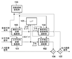
以下、本発明の実施の形態を図面に基づいて説明する。図1は、本発明の実施形態における画像処理装置の概略ブロックの一例を示す図である。図1において、水平方向座標換算部101は、重複領域設定部110で設定された水平方向の重複領域における画素座標値を、重複領域設定部110で設定可能な最大の水平方向の重複領域幅以上の領域の座標値に換算する。水平方向座標換算部101は、重複領域設定部110で設定された水平方向の重複領域において、画面端からの画素座標値(x)を(4)式で算出される座標値に換算する。
Hereinafter, embodiments of the present invention will be described with reference to the drawings. FIG. 1 is a diagram illustrating an example of a schematic block of an image processing apparatus according to an embodiment of the present invention. In FIG. 1, the horizontal
conv_x=W_max/Wh_set*x ・・・(4)
ここで、Wh_setは重複領域設定部110で設定可能な水平方向の設定重複領域幅である(図2)。W_maxは重複領域設定部110で設定可能な水平方向の最大の重複領域幅以上となる任意の領域の幅(座標値)であり(図2)、xは画面端からの水平方向の画素座標値(設定された重複領域における画素座標値)である。なお、xは、図2に示すような右側投射画面201の左側の重複領域においては画面左端からの距離を示す。また、xは画面の右側の重複領域においては画面右端からの距離を示す。
conv_x = W_max / Wh_set * x (4)
Here, Wh_set is a set overlap area width in the horizontal direction that can be set by the overlap area setting unit 110 (FIG. 2). W_max is the width (coordinate value) of an arbitrary area that is equal to or larger than the maximum horizontal overlapping area width that can be set by the overlapping area setting unit 110 (FIG. 2), and x is the pixel coordinate value in the horizontal direction from the screen edge. (Pixel coordinate value in the set overlapping region). Note that x represents the distance from the left edge of the screen in the left overlapping area of the
図2は2つの投射画面を水平方向に並べて構成したマルチスクリーン画面の構成例を示す図である。図2において、右側投射画面201と左側投射画面202とが重なる領域は重複領域203として示される。(4)式のWh_setは、重複領域203の水平方向の幅として示されている。換算重複領域203Aは重複領域203を(4)式で換算した領域を示す。重複領域203におけるxは、換算重複領域203Aのconv_xに対応する。図2では水平方向の重複領域を例示的に説明しているが、垂直方向の重複領域についても同様である。また、図2ではW_maxが水平方向の最大の重複領域幅と等しい場合を示す。
FIG. 2 is a diagram showing a configuration example of a multi-screen screen in which two projection screens are arranged in the horizontal direction. In FIG. 2, an area where the
説明を図1に戻し、LUT105は、重複領域の輝度を補正するための輝度補正データを格納するテーブルである。例えば、格納数をN、画像投射装置のガンマ特性をγとして、(5)式に示す輝度補正データを格納する。
Returning to FIG. 1, the
i/(N−1)<0.5の時
D(i)=(((i/(N−1)*2)^P)/2)^γ
0.5≦i/(N−1)の時
D(i)=(1−(((1−i/(N−1))*2)^P)/2)^γ
(i=0,1,…N−1)・・・(5)
ここで、(5)式により示される輝度補正データは重複領域203の両端で傾きが小さく、重複領域203の中央では直線となる所謂“S字”曲線となり、(5)式のPは輝度補正データの曲率を制御するパラメータである。
When i / (N-1) <0.5 D (i) = ((((i / (N-1) * 2) ^ P) / 2) ^ γ
When 0.5 ≦ i / (N−1) D (i) = (1 − (((1−i / (N−1)) * 2) ^ P) / 2) ^ γ
(I = 0, 1,... N−1) (5)
Here, the brightness correction data shown by the equation (5) has a small slope at both ends of the
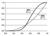
図3は、輝度補正データを例示する図であり、(5)式で算出される輝度補正データの値を縦軸に示し、横軸の値は、iをN−1で正規化したものである。“S字”曲線となる輝度補正データの例を図3の曲線301に示す(P=α)。 FIG. 3 is a diagram illustrating luminance correction data. The value of the luminance correction data calculated by equation (5) is shown on the vertical axis, and the value on the horizontal axis is obtained by normalizing i by N−1. is there. An example of luminance correction data that forms an “S-shaped” curve is shown by a curve 301 in FIG. 3 (P = α).
曲率を制御するパラメータP=1の場合(図3の曲線302)、i/(N−1)<0.5における輝度補正データD(i)は、D(i)=(i/(N−1))^γとなる。0.5≦i/(N−1)における輝度補正データD(i)は、D(i)=(1−(((1−i/(N−1))*2))/2)^γ=(i/(N−1))^γとなり、両者はともに直線として示される次式(i/(N−1))(i=0,1,…N−1)のγ乗となる。
When the parameter P = 1 for controlling the curvature (
水平補正係数補間演算部102は、水平方向座標換算部101で換算された座標値conv_xに応じて、(6)式で算出される2つのテーブル値(Dh0、Dh1)をLUT105から選択する。
The horizontal correction coefficient
Dh0=D(Sh)
Dh1=D(Sh+1)・・・(6)
ここで、Sh=int(conv_x/W_max*(N−1))
次に、水平補正係数補間演算部102は選択した2つのテーブル値Dh0,Dh1と水平方向座標換算部101で換算された座標値conv_xを用いて、(7)式で示す補間演算により水平方向の輝度補正係数(Dh)を算出する。
Dh0 = D (Sh)
Dh1 = D (Sh + 1) (6)
Here, Sh = int (conv_x / W_max * (N-1))
Next, the horizontal correction coefficient
Dh=Dh0+(Dh1−Dh0)/Ddis*eff_x・・・(7)
ここで、Ddis=W_max/(N−1)
eff_x=conv_x−Sh*Ddis
垂直方向座標換算部103は、重複領域設定部110で設定された垂直方向の重複領域における画素座標値を、重複領域設定部110で設定可能な最大の垂直方向の重複領域幅以上の領域の座標値に換算する。垂直方向座標換算部103は重複領域設定部110で設定された垂直方向の重複領域において、画面端からの画素座標値(y)を(8)式で算出される座標値に換算する。
Dh = Dh0 + (Dh1-Dh0) / Ddis * eff_x (7)
Where Ddis = W_max / (N−1)
eff_x = conv_x-Sh * Ddis
The vertical coordinate
conv_y=W_max/Wv_set*y ・・・(8)
ここで、Wv_setは重複領域設定部110で設定可能な垂直方向の設定重複領域幅である。W_maxは重複領域設定部110で設定可能な垂直方向の最大の重複領域幅以上となる任意の領域の幅(座標値)であり、yは画面端からの垂直方向の画素座標値(設定された重複領域における画素座標値)である。なお、yは、画面上側の重複領域においては画面上端からの距離を示す。また、yは画面下側の重複領域においては画面下端からの距離を示す。
conv_y = W_max / Wv_set * y (8)
Here, Wv_set is a set overlapping area width in the vertical direction that can be set by the overlapping
垂直補正係数補間演算部104は、垂直方向座標換算部103で換算された座標値conv_yに応じて、(9)式で算出される2つのテーブル値(Dv0、Dv1)をLUT105から選択する。
The vertical correction coefficient
Dv0=D(Sv)
Dv1=D(Sv+1) ・・・(9)
ここで、Sv=int(conv_y/W_max*(N−1))
次に、垂直補正係数補間演算部104は選択した2つのテーブル値Dv0,Dv1と垂直方向座標換算部103で換算されたconv_yとを用いて、(10)式で示す補間演算により垂直方向の輝度補正係数(Dv)を算出する。
Dv0 = D (Sv)
Dv1 = D (Sv + 1) (9)
Here, Sv = int (conv_y / W_max * (N-1))
Next, the vertical correction coefficient
Dv=Dv0+(Dv1−Dv0)/Ddis*eff_y・・・(10)
ここで、Ddis=W_max/(N−1)
eff_y=conv_y−Sv*Ddis
乗算部106(第1の乗算部)は、水平補正係数補間演算部102で算出した水平方向の輝度補正係数Dhを入力画像(入力画像信号)に乗算する(水平方向の輝度補正)。乗算部107(第2の乗算部)は、垂直補正係数補間演算部104で算出した垂直方向の輝度補正係数Dvを乗算部106から出力される乗算結果に乗算する(垂直方向の輝度補正)。
Dv = Dv0 + (Dv1-Dv0) / Ddis * eff_y (10)
Where Ddis = W_max / (N−1)
eff_y = conv_y-Sv * Ddis
The multiplication unit 106 (first multiplication unit) multiplies the input image (input image signal) by the horizontal luminance correction coefficient Dh calculated by the horizontal correction coefficient interpolation calculation unit 102 (horizontal luminance correction). The multiplication unit 107 (second multiplication unit) multiplies the multiplication result output from the
なお、本実施形態では水平方向の輝度補正後に垂直方向の輝度補正を行う構成としているが、補正順は逆であっても良い。 In this embodiment, the luminance correction in the vertical direction is performed after the luminance correction in the horizontal direction, but the correction order may be reversed.
ここまで、W_maxは任意の値として説明したが、具体的には、水平方向に関しては、重複領域設定部110で設定可能な水平方向の最大重複領域幅以上で2の累乗となる値とする。また、垂直方向に関しては、重複領域設定部110で設定可能なおよび垂直方向の最大重複領域幅以上で2の累乗となる値とする。また、LUT105の格納数Nは、(N−1)が2の累乗となる値とする。例えば、W_max=2^m、(N−1)=2^n(N=2^n+1)、m>n(m、n:自然数)とする。この場合、(6)式のSh、(9)式のSvはそれぞれ以下の(11)式、(12)式となる。
Up to this point, W_max has been described as an arbitrary value, but specifically, in the horizontal direction, it is set to a value that is a power of 2 above the maximum horizontal overlapping area width that can be set by the overlapping
Sh=int(conv_x/(2^(m−n)))・・・(11)
Sv=int(conv_y/(2^(m−n)))・・・(12)
ここで(4)式で算出されるconv_xおよび(8)式で算出されるconv_yは、mビットであるとすると、Shはconv_xの上位nビットの値と等しくなり、Svはconv_yの上位nビットの値と等しくなる。つまり、水平補正係数補間演算部102はconv_xの上位nビットを用いてLUT105のテーブル値の選択が可能となる。また、垂直補正係数補間演算部104はconv_yの上位nビットを用いてLUT105のテーブル値の選択が可能となる。
Sh = int (conv_x / (2 ^ (mn))) (11)
Sv = int (conv_y / (2 ^ (mn))) (12)
Here, if conv_x calculated by equation (4) and conv_y calculated by equation (8) are m bits, Sh is equal to the value of the upper n bits of conv_x, and Sv is the upper n bits of conv_y. Is equal to the value of. That is, the horizontal correction coefficient
また、(7)式のeff_xはconv_xの下位(m−n)ビットの値と等しくなり、(10)式のeff_yはconv_yの下位(m−n)ビットの値と等しくなる。つまり、conv_xおよびconv_yの下位(m−n)ビットを用いて補間係数演算が可能となる。さらに、(7)式および(10)式のDdisは2^(m−n)となり、1/Ddisの演算をシフト演算とすることが出来る。なお、本実施形態で、LUT105はテーブルとして構成しているが、この例に限定されるものでなく、例えば、レジスタとして構成することも可能である。また、本実施形態では、水平/垂直ともに最大の重複領域幅以上となる任意の領域の幅をW_maxとして説明したが、同じである必要は無い。
In addition, eff_x in equation (7) is equal to the value of the lower (mn) bits of conv_x, and eff_y in equation (10) is equal to the value of the lower (mn) bits of conv_y. In other words, the interpolation coefficient can be calculated using the lower (mn) bits of conv_x and conv_y. Further, Ddis in the equations (7) and (10) is 2 ^ (mn), and the calculation of 1 / Ddis can be a shift operation. In the present embodiment, the
また、図4は、投影画面の重複領域の輝度を補正する画像処理装置の画像処理方法の処理の流れを説明するフローチャートである。 FIG. 4 is a flowchart for explaining the processing flow of the image processing method of the image processing apparatus for correcting the luminance of the overlapping area of the projection screen.
ステップS410において、重複領域設定部110は投影画面における重複領域を設定する。ステップS420において、座標換算部(水平方向座標換算部101、垂直方向座標換算部103)が、重複領域の座標値を、ステップS410の設定工程で設定可能な最大の重複領域幅以上の重複領域の座標値に換算する。
In step S410, the overlapping
ステップS430において、補間演算部が、換算された座標値に応じて輝度補正データ格納手段から2つのデータを選択し、選択した輝度補正データと換算された座標値と、を用いて輝度補正データを算出する。ここで、水平補正係数補間演算部102および垂直補正係数補間演算部104は、ステップS430の補間演算部として機能する。ステップS440において、補正部(乗算部106、乗算部107)が、選択した輝度補正データと輝度補正係数とを用いて重複領域の輝度を補正する。
In step S430, the interpolation calculation unit selects two pieces of data from the luminance correction data storage unit according to the converted coordinate value, and uses the selected luminance correction data and the converted coordinate value to obtain the luminance correction data. calculate. Here, the horizontal correction coefficient
本実施形態によれば、複数の投射型画像表示装置で構成するマルチスクリーン画面において、隣接する投射型画像表示装置との画像重複領域における輝度補正精度を低下することなく、任意の重複領域幅を設定することが可能になる。
(その他の実施形態)
また、本発明は、以下の処理を実行することによっても実現される。即ち、上述した実施形態の機能を実現するソフトウェア(プログラム)を、ネットワーク又は各種記憶媒体を介してシステム或いは装置に供給し、そのシステム或いは装置のコンピュータ(またはCPUやMPU等)がプログラムを読み出して実行する処理である。
According to the present embodiment, in a multi-screen screen configured by a plurality of projection type image display devices, an arbitrary overlapping region width can be obtained without reducing luminance correction accuracy in an image overlapping region with an adjacent projection type image display device. It becomes possible to set.
(Other embodiments)
The present invention can also be realized by executing the following processing. That is, software (program) that realizes the functions of the above-described embodiments is supplied to a system or apparatus via a network or various storage media, and a computer (or CPU, MPU, or the like) of the system or apparatus reads the program. It is a process to be executed.
Claims (11)
前記投影画面における重複領域を設定する設定手段と、
前記重複領域の輝度を補正するための複数の輝度補正データを格納する格納手段と、
前記設定手段により設定された重複領域上の座標値を、前記設定手段で設定可能な最大の重複領域幅以上に対応する領域上の座標値に換算する座標換算手段と、
前記座標換算手段により換算された座標値に対応する第1輝度補正データと、前記第1輝度補正データの座標上次のデータに対応する第2輝度補正データとを選択し、選択された前記第1輝度補正データ及び前記第2輝度補正データと、前記設定手段で設定可能な最大の重複領域幅以上に対応する領域の領域幅と、前記複数の輝度補正データのデータ数と、前記換算された座標値とを用いて、前記第1輝度補正データと前記第2輝度補正データの間の値を補間して輝度補正係数を算出する補間演算手段と、
前記補間演算手段により算出された輝度補正係数を用いて前記重複領域の輝度を補正する補正手段と、
を備えることを特徴とする画像処理装置。 An image processing device that corrects the luminance of an overlapping area of a projection screen projected by a plurality of image display devices,
Setting means for setting an overlapping area in the projection screen;
Storage means for storing a plurality of brightness correction data for correcting the brightness of the overlapping region;
A coordinate conversion means for converting the coordinate value on the overlapping area set by the setting means to a coordinate value on an area corresponding to the maximum overlapping area width settable by the setting means;
The first luminance correction data corresponding to the coordinate value converted by the coordinate conversion means and the second luminance correction data corresponding to the next data on the coordinates of the first luminance correction data are selected, and the selected first 1 brightness correction data and the 2nd brightness correction data, the area width of the area corresponding to more than the maximum overlap area width settable by the setting means, the number of data of the plurality of brightness correction data, and the converted Interpolation calculation means for calculating a luminance correction coefficient by interpolating a value between the first luminance correction data and the second luminance correction data using coordinate values ;
Correction means for correcting the luminance of the overlapping region using the luminance correction coefficient calculated by the interpolation calculation means;
An image processing apparatus comprising:
前記座標換算手段は、前記重複領域の座標値を前記最大の重複領域幅以上に対応する領域上の座標値であって、mビット(m:自然数、m>n)の座標値に換算することを特徴とする請求項1に記載の画像処理装置。 The storage means stores N (N = 2 ^ n + 1 (n: natural number)) luminance correction data,
The coordinate conversion means converts the coordinate value of the overlap area into a coordinate value on an area corresponding to the width of the maximum overlap area or more, and is converted to an m-bit (m: natural number, m> n) coordinate value. The image processing apparatus according to claim 1.
前記投影画面における重複領域を設定する設定工程と、
前記設定工程で設定された重複領域上の座標値を、前記設定工程で設定可能な最大の重複領域幅以上に対応する領域上の座標値に換算する座標換算工程と、
前記座標換算工程で換算された座標値に対応する第1輝度補正データと、前記第1輝度補正データの座標上次のデータに対応する第2輝度補正データとを選択し、選択された前記第1輝度補正データ及び前記第2輝度補正データと、前記設定工程で設定可能な最大の重複領域幅以上に対応する領域の領域幅と、前記重複領域の輝度を補正するための複数の輝度補正データのデータ数と、前記換算された座標値とを用いて、前記第1輝度補正データと前記第2輝度補正データの間の値を補間して輝度補正係数を算出する補間演算工程と、
前記算出された輝度補正係数を用いて前記重複領域の輝度を補正する補正工程と、
を有することを特徴とする画像処理方法。 An image processing method performed by an image processing apparatus that corrects luminance of an overlapping area of a projection screen projected by a plurality of image display apparatuses,
A setting step for setting an overlapping area in the projection screen;
A coordinate conversion step of converting the coordinate value on the overlapping region set in the setting step into a coordinate value on the region corresponding to the maximum overlapping region width that can be set in the setting step;
The first luminance correction data corresponding to the coordinate value converted in the coordinate conversion step and the second luminance correction data corresponding to the next data on the coordinates of the first luminance correction data are selected, and the selected first 1 brightness correction data and the 2nd brightness correction data, the area width of the area corresponding to more than the maximum overlap area width that can be set in the setting step, and a plurality of brightness correction data for correcting the brightness of the overlap area An interpolation calculation step of calculating a luminance correction coefficient by interpolating a value between the first luminance correction data and the second luminance correction data using the data number and the converted coordinate value ;
A correction step of correcting the luminance of the overlapping region using the calculated luminance correction coefficient;
An image processing method comprising:
前記座標換算工程は、前記重複領域の座標値を前記最大の重複領域幅以上に対応する領域上の座標値であって、mビット(m:自然数、m>n)の座標値に換算することを特徴とする請求項6に記載の画像処理方法。 Store means N: stores (N = 2 ^ n + 1 (n a natural number)) pieces of the luminance correction data,
In the coordinate conversion step, the coordinate value of the overlapping area is a coordinate value on an area corresponding to the width of the maximum overlapping area or more, and is converted into an m-bit (m: natural number, m> n) coordinate value. The image processing method according to claim 6 .
Priority Applications (2)
| Application Number | Priority Date | Filing Date | Title |
|---|---|---|---|
| JP2013024913A JP6300444B2 (en) | 2013-02-12 | 2013-02-12 | Image processing apparatus, image processing method, and program |
| US14/173,925 US9191638B2 (en) | 2013-02-12 | 2014-02-06 | Image processing apparatus, image processing method and storage medium |
Applications Claiming Priority (1)
| Application Number | Priority Date | Filing Date | Title |
|---|---|---|---|
| JP2013024913A JP6300444B2 (en) | 2013-02-12 | 2013-02-12 | Image processing apparatus, image processing method, and program |
Publications (3)
| Publication Number | Publication Date |
|---|---|
| JP2014153627A JP2014153627A (en) | 2014-08-25 |
| JP2014153627A5 JP2014153627A5 (en) | 2016-03-24 |
| JP6300444B2 true JP6300444B2 (en) | 2018-03-28 |
Family
ID=51297165
Family Applications (1)
| Application Number | Title | Priority Date | Filing Date |
|---|---|---|---|
| JP2013024913A Expired - Fee Related JP6300444B2 (en) | 2013-02-12 | 2013-02-12 | Image processing apparatus, image processing method, and program |
Country Status (2)
| Country | Link |
|---|---|
| US (1) | US9191638B2 (en) |
| JP (1) | JP6300444B2 (en) |
Families Citing this family (5)
| Publication number | Priority date | Publication date | Assignee | Title |
|---|---|---|---|---|
| CN107422590B (en) * | 2017-09-12 | 2020-09-08 | 中广热点云科技有限公司 | Household projection system capable of automatically adjusting size of projection surface |
| JP2019078786A (en) | 2017-10-20 | 2019-05-23 | セイコーエプソン株式会社 | Image projection system, projector, and control method of image projection system |
| JP6915597B2 (en) | 2018-08-29 | 2021-08-04 | セイコーエプソン株式会社 | Controls, multi-projection systems, and control methods for controls |
| CN113539165B (en) * | 2021-07-30 | 2023-04-07 | 合肥维信诺科技有限公司 | Gamma debugging method, device and equipment for display panel and storage medium |
| CN114584747B (en) * | 2022-03-04 | 2023-10-31 | 大连海事大学 | 360-degree annular curtain seamless projection soft correction method |
Family Cites Families (6)
| Publication number | Priority date | Publication date | Assignee | Title |
|---|---|---|---|---|
| JP3752448B2 (en) * | 2001-12-05 | 2006-03-08 | オリンパス株式会社 | Image display system |
| JP3620537B2 (en) * | 2003-05-02 | 2005-02-16 | セイコーエプソン株式会社 | Image processing system, projector, program, information storage medium, and image processing method |
| JP2005117266A (en) | 2003-10-06 | 2005-04-28 | Sony Corp | Drive circuit for image projection system |
| JP4501481B2 (en) * | 2004-03-22 | 2010-07-14 | セイコーエプソン株式会社 | Image correction method for multi-projection system |
| US7292207B1 (en) * | 2004-08-27 | 2007-11-06 | Sun Microsystems, Inc. | Computing blending functions for the tiling of overlapped video projectors |
| JP2007295026A (en) * | 2006-04-20 | 2007-11-08 | Victor Co Of Japan Ltd | Luminance correction apparatus in multi-projection system |
-
2013
- 2013-02-12 JP JP2013024913A patent/JP6300444B2/en not_active Expired - Fee Related
-
2014
- 2014-02-06 US US14/173,925 patent/US9191638B2/en not_active Expired - Fee Related
Also Published As
| Publication number | Publication date |
|---|---|
| JP2014153627A (en) | 2014-08-25 |
| US9191638B2 (en) | 2015-11-17 |
| US20140225909A1 (en) | 2014-08-14 |
Similar Documents
| Publication | Publication Date | Title |
|---|---|---|
| JP6300444B2 (en) | Image processing apparatus, image processing method, and program | |
| JP6274746B2 (en) | Projection type image display apparatus, projection image display method, and computer program | |
| JP2008205691A5 (en) | ||
| JP5744586B2 (en) | Liquid crystal display device and program used therefor | |
| US9761158B2 (en) | Image processing apparatus, image processing method, and storage medium | |
| JP2019120749A (en) | Display controller, image projection system, control method and program | |
| JP2007072650A (en) | Gamma curve generation method and its device | |
| AU2013383810B2 (en) | Color conversion method, gray scale value correction apparatus, computer program and display apparatus | |
| JP6425264B2 (en) | Color conversion data generation device, color conversion data generation method, and display device | |
| US10152945B2 (en) | Image processing apparatus capable of performing conversion on input image data for wide dynamic range | |
| JP2012138897A5 (en) | ||
| JP4131158B2 (en) | Video signal processing device, gamma correction method, and display device | |
| JP2014153627A5 (en) | ||
| JP5025323B2 (en) | Color processing apparatus and method | |
| CN102752608A (en) | Method and device for realizing fast color correction | |
| JP5096247B2 (en) | Image processing apparatus and method | |
| JP2015080019A (en) | Image processor and image processing method | |
| JP2008067233A (en) | Digital-watermarking embedding method, program, and computer-readable recording medium | |
| US9460498B2 (en) | Image processing method and image processing device | |
| JP7346039B2 (en) | Data processing device, data processing method, and program | |
| JP2015126301A (en) | Image processor and image processing method | |
| CN102413269B (en) | Video processing method and circuit applying method | |
| JP2010048973A5 (en) | ||
| JP2018121139A (en) | Image correction device, image correction method, and program | |
| US20130330018A1 (en) | Image processing apparatus and image processing method |
Legal Events
| Date | Code | Title | Description |
|---|---|---|---|
| A521 | Request for written amendment filed |
Free format text: JAPANESE INTERMEDIATE CODE: A523 Effective date: 20160203 |
|
| A621 | Written request for application examination |
Free format text: JAPANESE INTERMEDIATE CODE: A621 Effective date: 20160203 |
|
| A977 | Report on retrieval |
Free format text: JAPANESE INTERMEDIATE CODE: A971007 Effective date: 20161129 |
|
| A131 | Notification of reasons for refusal |
Free format text: JAPANESE INTERMEDIATE CODE: A131 Effective date: 20161205 |
|
| A521 | Request for written amendment filed |
Free format text: JAPANESE INTERMEDIATE CODE: A523 Effective date: 20170127 |
|
| A131 | Notification of reasons for refusal |
Free format text: JAPANESE INTERMEDIATE CODE: A131 Effective date: 20170630 |
|
| A521 | Request for written amendment filed |
Free format text: JAPANESE INTERMEDIATE CODE: A523 Effective date: 20170828 |
|
| TRDD | Decision of grant or rejection written | ||
| A01 | Written decision to grant a patent or to grant a registration (utility model) |
Free format text: JAPANESE INTERMEDIATE CODE: A01 Effective date: 20180129 |
|
| A61 | First payment of annual fees (during grant procedure) |
Free format text: JAPANESE INTERMEDIATE CODE: A61 Effective date: 20180227 |
|
| R151 | Written notification of patent or utility model registration |
Ref document number: 6300444 Country of ref document: JP Free format text: JAPANESE INTERMEDIATE CODE: R151 |
|
| LAPS | Cancellation because of no payment of annual fees |