JP6298708B2 - Multi-axis screw machine for processing materials - Google Patents
Multi-axis screw machine for processing materials Download PDFInfo
- Publication number
- JP6298708B2 JP6298708B2 JP2014102168A JP2014102168A JP6298708B2 JP 6298708 B2 JP6298708 B2 JP 6298708B2 JP 2014102168 A JP2014102168 A JP 2014102168A JP 2014102168 A JP2014102168 A JP 2014102168A JP 6298708 B2 JP6298708 B2 JP 6298708B2
- Authority
- JP
- Japan
- Prior art keywords
- partial
- screw machine
- axis
- axes
- shafts
- Prior art date
- Legal status (The legal status is an assumption and is not a legal conclusion. Google has not performed a legal analysis and makes no representation as to the accuracy of the status listed.)
- Active
Links
- 239000000463 material Substances 0.000 title claims description 32
- 230000005540 biological transmission Effects 0.000 claims description 28
- 238000004898 kneading Methods 0.000 claims description 28
- 230000036316 preload Effects 0.000 claims description 20
- 238000002844 melting Methods 0.000 claims description 14
- 230000008018 melting Effects 0.000 claims description 14
- 229960001716 benzalkonium Drugs 0.000 claims 1
- CYDRXTMLKJDRQH-UHFFFAOYSA-N benzododecinium Chemical compound CCCCCCCCCCCC[N+](C)(C)CC1=CC=CC=C1 CYDRXTMLKJDRQH-UHFFFAOYSA-N 0.000 claims 1
- 238000004519 manufacturing process Methods 0.000 description 17
- 238000010438 heat treatment Methods 0.000 description 8
- 238000009826 distribution Methods 0.000 description 6
- 239000000155 melt Substances 0.000 description 6
- 239000000654 additive Substances 0.000 description 5
- 230000000996 additive effect Effects 0.000 description 5
- 238000000265 homogenisation Methods 0.000 description 5
- 230000009467 reduction Effects 0.000 description 5
- 238000011144 upstream manufacturing Methods 0.000 description 5
- 238000007872 degassing Methods 0.000 description 4
- 230000004323 axial length Effects 0.000 description 3
- 230000001771 impaired effect Effects 0.000 description 2
- 238000003754 machining Methods 0.000 description 2
- 238000000034 method Methods 0.000 description 2
- 238000013022 venting Methods 0.000 description 2
- 229910000617 Mangalloy Inorganic materials 0.000 description 1
- 230000008859 change Effects 0.000 description 1
- 230000000694 effects Effects 0.000 description 1
- 230000004044 response Effects 0.000 description 1
Images


Classifications
-
- B—PERFORMING OPERATIONS; TRANSPORTING
- B29—WORKING OF PLASTICS; WORKING OF SUBSTANCES IN A PLASTIC STATE IN GENERAL
- B29B—PREPARATION OR PRETREATMENT OF THE MATERIAL TO BE SHAPED; MAKING GRANULES OR PREFORMS; RECOVERY OF PLASTICS OR OTHER CONSTITUENTS OF WASTE MATERIAL CONTAINING PLASTICS
- B29B7/00—Mixing; Kneading
- B29B7/30—Mixing; Kneading continuous, with mechanical mixing or kneading devices
- B29B7/34—Mixing; Kneading continuous, with mechanical mixing or kneading devices with movable mixing or kneading devices
- B29B7/38—Mixing; Kneading continuous, with mechanical mixing or kneading devices with movable mixing or kneading devices rotary
- B29B7/46—Mixing; Kneading continuous, with mechanical mixing or kneading devices with movable mixing or kneading devices rotary with more than one shaft
- B29B7/48—Mixing; Kneading continuous, with mechanical mixing or kneading devices with movable mixing or kneading devices rotary with more than one shaft with intermeshing devices, e.g. screws
- B29B7/482—Mixing; Kneading continuous, with mechanical mixing or kneading devices with movable mixing or kneading devices rotary with more than one shaft with intermeshing devices, e.g. screws provided with screw parts in addition to other mixing parts, e.g. paddles, gears, discs
- B29B7/483—Mixing; Kneading continuous, with mechanical mixing or kneading devices with movable mixing or kneading devices rotary with more than one shaft with intermeshing devices, e.g. screws provided with screw parts in addition to other mixing parts, e.g. paddles, gears, discs the other mixing parts being discs perpendicular to the screw axis
-
- B—PERFORMING OPERATIONS; TRANSPORTING
- B29—WORKING OF PLASTICS; WORKING OF SUBSTANCES IN A PLASTIC STATE IN GENERAL
- B29B—PREPARATION OR PRETREATMENT OF THE MATERIAL TO BE SHAPED; MAKING GRANULES OR PREFORMS; RECOVERY OF PLASTICS OR OTHER CONSTITUENTS OF WASTE MATERIAL CONTAINING PLASTICS
- B29B7/00—Mixing; Kneading
- B29B7/30—Mixing; Kneading continuous, with mechanical mixing or kneading devices
- B29B7/34—Mixing; Kneading continuous, with mechanical mixing or kneading devices with movable mixing or kneading devices
- B29B7/38—Mixing; Kneading continuous, with mechanical mixing or kneading devices with movable mixing or kneading devices rotary
- B29B7/46—Mixing; Kneading continuous, with mechanical mixing or kneading devices with movable mixing or kneading devices rotary with more than one shaft
- B29B7/48—Mixing; Kneading continuous, with mechanical mixing or kneading devices with movable mixing or kneading devices rotary with more than one shaft with intermeshing devices, e.g. screws
- B29B7/481—Mixing; Kneading continuous, with mechanical mixing or kneading devices with movable mixing or kneading devices rotary with more than one shaft with intermeshing devices, e.g. screws provided with paddles, gears or discs
-
- B—PERFORMING OPERATIONS; TRANSPORTING
- B29—WORKING OF PLASTICS; WORKING OF SUBSTANCES IN A PLASTIC STATE IN GENERAL
- B29B—PREPARATION OR PRETREATMENT OF THE MATERIAL TO BE SHAPED; MAKING GRANULES OR PREFORMS; RECOVERY OF PLASTICS OR OTHER CONSTITUENTS OF WASTE MATERIAL CONTAINING PLASTICS
- B29B7/00—Mixing; Kneading
- B29B7/30—Mixing; Kneading continuous, with mechanical mixing or kneading devices
- B29B7/34—Mixing; Kneading continuous, with mechanical mixing or kneading devices with movable mixing or kneading devices
- B29B7/38—Mixing; Kneading continuous, with mechanical mixing or kneading devices with movable mixing or kneading devices rotary
- B29B7/46—Mixing; Kneading continuous, with mechanical mixing or kneading devices with movable mixing or kneading devices rotary with more than one shaft
- B29B7/48—Mixing; Kneading continuous, with mechanical mixing or kneading devices with movable mixing or kneading devices rotary with more than one shaft with intermeshing devices, e.g. screws
- B29B7/488—Parts, e.g. casings, sealings; Accessories, e.g. flow controlling or throttling devices
-
- B—PERFORMING OPERATIONS; TRANSPORTING
- B29—WORKING OF PLASTICS; WORKING OF SUBSTANCES IN A PLASTIC STATE IN GENERAL
- B29C—SHAPING OR JOINING OF PLASTICS; SHAPING OF MATERIAL IN A PLASTIC STATE, NOT OTHERWISE PROVIDED FOR; AFTER-TREATMENT OF THE SHAPED PRODUCTS, e.g. REPAIRING
- B29C48/00—Extrusion moulding, i.e. expressing the moulding material through a die or nozzle which imparts the desired form; Apparatus therefor
- B29C48/25—Component parts, details or accessories; Auxiliary operations
- B29C48/256—Exchangeable extruder parts
- B29C48/2561—Mounting or handling of the screw
-
- B—PERFORMING OPERATIONS; TRANSPORTING
- B29—WORKING OF PLASTICS; WORKING OF SUBSTANCES IN A PLASTIC STATE IN GENERAL
- B29C—SHAPING OR JOINING OF PLASTICS; SHAPING OF MATERIAL IN A PLASTIC STATE, NOT OTHERWISE PROVIDED FOR; AFTER-TREATMENT OF THE SHAPED PRODUCTS, e.g. REPAIRING
- B29C48/00—Extrusion moulding, i.e. expressing the moulding material through a die or nozzle which imparts the desired form; Apparatus therefor
- B29C48/25—Component parts, details or accessories; Auxiliary operations
- B29C48/256—Exchangeable extruder parts
- B29C48/2564—Screw parts
-
- B—PERFORMING OPERATIONS; TRANSPORTING
- B29—WORKING OF PLASTICS; WORKING OF SUBSTANCES IN A PLASTIC STATE IN GENERAL
- B29C—SHAPING OR JOINING OF PLASTICS; SHAPING OF MATERIAL IN A PLASTIC STATE, NOT OTHERWISE PROVIDED FOR; AFTER-TREATMENT OF THE SHAPED PRODUCTS, e.g. REPAIRING
- B29C48/00—Extrusion moulding, i.e. expressing the moulding material through a die or nozzle which imparts the desired form; Apparatus therefor
- B29C48/25—Component parts, details or accessories; Auxiliary operations
- B29C48/256—Exchangeable extruder parts
- B29C48/2568—Inserts
- B29C48/25682—Inserts for screws
-
- B—PERFORMING OPERATIONS; TRANSPORTING
- B29—WORKING OF PLASTICS; WORKING OF SUBSTANCES IN A PLASTIC STATE IN GENERAL
- B29C—SHAPING OR JOINING OF PLASTICS; SHAPING OF MATERIAL IN A PLASTIC STATE, NOT OTHERWISE PROVIDED FOR; AFTER-TREATMENT OF THE SHAPED PRODUCTS, e.g. REPAIRING
- B29C48/00—Extrusion moulding, i.e. expressing the moulding material through a die or nozzle which imparts the desired form; Apparatus therefor
- B29C48/25—Component parts, details or accessories; Auxiliary operations
- B29C48/266—Means for allowing relative movements between the apparatus parts, e.g. for twisting the extruded article or for moving the die along a surface to be coated
- B29C48/2665—Means for allowing relative movements between the apparatus parts, e.g. for twisting the extruded article or for moving the die along a surface to be coated allowing small relative movement, e.g. adjustments for aligning the apparatus parts or for compensating for thermal expansion
-
- B—PERFORMING OPERATIONS; TRANSPORTING
- B29—WORKING OF PLASTICS; WORKING OF SUBSTANCES IN A PLASTIC STATE IN GENERAL
- B29C—SHAPING OR JOINING OF PLASTICS; SHAPING OF MATERIAL IN A PLASTIC STATE, NOT OTHERWISE PROVIDED FOR; AFTER-TREATMENT OF THE SHAPED PRODUCTS, e.g. REPAIRING
- B29C48/00—Extrusion moulding, i.e. expressing the moulding material through a die or nozzle which imparts the desired form; Apparatus therefor
- B29C48/25—Component parts, details or accessories; Auxiliary operations
- B29C48/36—Means for plasticising or homogenising the moulding material or forcing it through the nozzle or die
- B29C48/395—Means for plasticising or homogenising the moulding material or forcing it through the nozzle or die using screws surrounded by a cooperating barrel, e.g. single screw extruders
- B29C48/40—Means for plasticising or homogenising the moulding material or forcing it through the nozzle or die using screws surrounded by a cooperating barrel, e.g. single screw extruders using two or more parallel screws or at least two parallel non-intermeshing screws, e.g. twin screw extruders
- B29C48/405—Intermeshing co-rotating screws
-
- B—PERFORMING OPERATIONS; TRANSPORTING
- B29—WORKING OF PLASTICS; WORKING OF SUBSTANCES IN A PLASTIC STATE IN GENERAL
- B29C—SHAPING OR JOINING OF PLASTICS; SHAPING OF MATERIAL IN A PLASTIC STATE, NOT OTHERWISE PROVIDED FOR; AFTER-TREATMENT OF THE SHAPED PRODUCTS, e.g. REPAIRING
- B29C48/00—Extrusion moulding, i.e. expressing the moulding material through a die or nozzle which imparts the desired form; Apparatus therefor
- B29C48/25—Component parts, details or accessories; Auxiliary operations
- B29C48/36—Means for plasticising or homogenising the moulding material or forcing it through the nozzle or die
- B29C48/50—Details of extruders
- B29C48/505—Screws
- B29C48/507—Screws characterised by the material or their manufacturing process
-
- B—PERFORMING OPERATIONS; TRANSPORTING
- B29—WORKING OF PLASTICS; WORKING OF SUBSTANCES IN A PLASTIC STATE IN GENERAL
- B29C—SHAPING OR JOINING OF PLASTICS; SHAPING OF MATERIAL IN A PLASTIC STATE, NOT OTHERWISE PROVIDED FOR; AFTER-TREATMENT OF THE SHAPED PRODUCTS, e.g. REPAIRING
- B29C48/00—Extrusion moulding, i.e. expressing the moulding material through a die or nozzle which imparts the desired form; Apparatus therefor
- B29C48/25—Component parts, details or accessories; Auxiliary operations
- B29C48/36—Means for plasticising or homogenising the moulding material or forcing it through the nozzle or die
- B29C48/50—Details of extruders
- B29C48/505—Screws
- B29C48/57—Screws provided with kneading disc-like elements, e.g. with oval-shaped elements
-
- B—PERFORMING OPERATIONS; TRANSPORTING
- B30—PRESSES
- B30B—PRESSES IN GENERAL
- B30B11/00—Presses specially adapted for forming shaped articles from material in particulate or plastic state, e.g. briquetting presses, tabletting presses
- B30B11/22—Extrusion presses; Dies therefor
- B30B11/24—Extrusion presses; Dies therefor using screws or worms
- B30B11/243—Extrusion presses; Dies therefor using screws or worms using two or more screws working in the same chamber
-
- B—PERFORMING OPERATIONS; TRANSPORTING
- B30—PRESSES
- B30B—PRESSES IN GENERAL
- B30B11/00—Presses specially adapted for forming shaped articles from material in particulate or plastic state, e.g. briquetting presses, tabletting presses
- B30B11/22—Extrusion presses; Dies therefor
- B30B11/24—Extrusion presses; Dies therefor using screws or worms
- B30B11/246—Screw constructions
Description
本発明は、材料、特に請求項1の前文(プリアンブル部分、所謂おいて書き部分)に記載のプラスチック材料を加工するための多軸スクリュー機械に関する。 The present invention relates to a multi-screw machine for processing materials, in particular the plastic material according to the preamble of claim 1 (preamble part, so-called writing part).
プラスチック加工用のスクリュー機械が、同一方向の回転のために駆動可能な2つの処理要素軸を有する特許文献1(特許文献2に対応)から公知である。処理要素軸はモジュラー構造を有し、処理要素軸の各々は、ランダムオーダで互いに前後に配置された異なる処理要素が設けられる軸を有する。処理要素は、確実なトルク伝達を可能にするように、キーによってそれぞれの軸に回転しないように配置される。処理要素がランダムオーダで軸に配置可能であるという事実によって、処理要素軸は、搬送、可塑化、均質化及び圧力増大のような非常に異なる操作を実行する簡単な方法を提供する。しかし、処理要素軸の製造は複雑であり、したがって、著しい金額を必要とする。 A screw machine for plastic processing is known from Patent Document 1 (corresponding to Patent Document 2) having two processing element shafts that can be driven for rotation in the same direction. The processing element axes have a modular structure, and each of the processing element axes has an axis on which different processing elements are arranged one after the other in a random order. The processing elements are arranged so as not to rotate on their respective axes by means of a key so as to allow a reliable torque transmission. Due to the fact that the processing elements can be arranged on the shaft in a random order, the processing element shaft provides a simple way to perform very different operations such as transport, plasticization, homogenization and pressure increase. However, the manufacture of the processing element shaft is complex and therefore requires significant amounts of money.
特許文献3(特許文献4に対応)は、スクリュー機械を開示しており、その軸は、材料送り込みの領域の2つの部分に分割される。これにより、材料送り込みに使用されるスクリュー部材の容易な交換が可能になる。 Patent document 3 (corresponding to patent document 4) discloses a screw machine whose axis is divided into two parts in the region of material feeding. Thereby, an easy exchange of the screw member used for material feeding becomes possible.
本発明の目的は、比較的低い製造コストでモジュラー構造の実装及び高いトルクの伝達の達成を可能にする多軸スクリュー機械を提供することである。 It is an object of the present invention to provide a multi-screw machine that makes it possible to implement a modular structure and achieve high torque transmission at a relatively low production cost.
この目的は、請求項1に記載の特徴を有する多軸スクリュー機械によって達成される。従来技術と対照的に、少なくとも2つの軸が一部片で形成されず、複数の部分軸から構成されるという事実のため、同様に、軸は、処理要素軸の製造コストの低減を可能にするモジュラー構造を有する。少なくとも2つの軸は、各々少なくとも2つの部分軸から、特に少なくとも3つの部分軸から構成されることが好ましい。好ましくは、少なくとも2つの軸は、同一の方法で部分軸から構成される。部分軸の間の継手の領域の軸のトルク伝達率は、一体構造のトルク伝達率と比較して低減される。しかし、この低減は、2つの接続された部分軸に重なり合うようにそれぞれの継手に回転しないように配置される処理要素によって実質的に補償される。それぞれの処理要素は、例えば、スクリュー要素又は混練要素として構成することができる。このために、混練要素は、一部片を形成するように互いに接続される複数の混練ディスクを備えるいわゆる混練ブロックとして構成される。 This object is achieved by a multi-screw machine having the features of claim 1. In contrast to the prior art, due to the fact that at least two shafts are not formed in one piece but consist of a plurality of partial shafts, the shafts likewise allow a reduction in the manufacturing costs of the processing element shafts. It has a modular structure. The at least two axes are each preferably composed of at least two partial axes, in particular at least three partial axes. Preferably, at least two axes are composed of partial axes in the same way. The torque transmission rate of the shaft in the region of the joint between the partial shafts is reduced compared to the torque transmission rate of the monolithic structure. However, this reduction is substantially compensated by the processing elements arranged so as not to rotate in the respective joints so as to overlap the two connected partial axes. Each processing element can be configured, for example, as a screw element or a kneading element. For this purpose, the kneading element is configured as a so-called kneading block comprising a plurality of kneading disks connected to one another so as to form a partial piece.
第1の部分軸がそれぞれスクリュー機械の溶融区間内まで少なくとも延び、また少なくとも1つの混練要素が第1の部分軸の各々に回転しないように配置されるという事実のため、製造コストの低減を確実にしつつ、確実なトルク伝達が保証される。処理要素軸に供給される機械的なエネルギーの最大部分は、それぞれの第1の混練要素で転換され、言い換えれば、加工されるべき材料に導入される。このことは、最高のトルクが第1の混練要素の領域に生じることを意味する。第1の混練要素の全体が各々第1の部分軸に配置されるという事実のため、最高のトルクが継手の領域に又は継手の背後に生じず、したがって、著しく確実なトルク伝達が確実にされる。この結果、継手の領域の軸の破損を有効に防止することができる。溶融区間の第1の部分軸には、したがって、混練要素の形態の処理要素が設けられる。それぞれの混練要素は、一部片を形成するように互いに接続される複数の混練ディスクを備える混練ブロックとして構成される。 The fact that the first partial shafts each extend at least into the melting section of the screw machine and that at least one kneading element is arranged not to rotate on each of the first partial shafts ensures a reduction in production costs In addition, reliable torque transmission is guaranteed. The largest part of the mechanical energy supplied to the processing element shaft is converted in each first kneading element, in other words introduced into the material to be processed. This means that the highest torque is generated in the region of the first kneading element. Due to the fact that the whole of the first kneading elements are each arranged on the first partial shaft, the highest torque does not occur in the area of the joint or behind the joint, thus ensuring a very reliable torque transmission. The As a result, breakage of the shaft in the joint region can be effectively prevented. The first partial axis of the melting zone is therefore provided with a processing element in the form of a kneading element. Each kneading element is configured as a kneading block comprising a plurality of kneading disks connected to each other so as to form a partial piece.
軸に配置された処理要素は、通常の方法で上流端及び下流端に取り付けられたストッパによって回転軸線の方向に固定される。上流端では、固定は、例えばケーシング閉鎖要素によって行われ、下流端では、固定は、例えば軸先端又はスクリュー先端によって達成される。軸先端は、各々最後の部分軸に固定可能である。 The processing elements arranged on the shaft are fixed in the direction of the axis of rotation by stoppers attached to the upstream and downstream ends in the usual manner. At the upstream end, the fixation is effected, for example, by a casing closure element, and at the downstream end, the fixation is achieved, for example, by a shaft tip or a screw tip. Each shaft tip can be fixed to the last partial shaft.
本発明の多軸スクリュー機械の製造コストは、軸が比較的長く及び/又は比較的大きな直径を有する場合、特に低減することができる。一体の軸と比較して、部分軸は、特殊な機械を必要とすることなく容易に製造可能かつ加工可能である。さらに、部分軸は、要件に従って製造又は加工することができ、これにより、軸用に最適化された製造プロセスが得られる。 The manufacturing costs of the inventive multi-screw machine can be reduced especially when the shaft is relatively long and / or has a relatively large diameter. Compared to the integral shaft, the partial shaft can be easily manufactured and machined without the need for a special machine. Furthermore, the partial shaft can be manufactured or machined according to the requirements, which results in a manufacturing process optimized for the shaft.
軸は複数の部分軸から組み立てられるので、処理要素を軸に容易に装備することを可能にしつつ、軸のモジュラー構造が容易に実装される。各々部分軸に重なり合うように継手に配置される処理要素により、軸又は処理要素軸それぞれのトルク伝達率が実質的に損なわれないことが確実にされる。この結果、製造コストを低減することができる。 Since the shaft is assembled from a plurality of partial shafts, a modular structure of the shaft is easily implemented while allowing processing elements to be easily mounted on the shaft. The processing elements arranged in the joint so as to overlap each partial axis ensures that the torque transmission rate of the shaft or each processing element shaft is not substantially impaired. As a result, the manufacturing cost can be reduced.
一方で、請求項2に記載の多軸スクリュー機械は、部分軸に重なり合うように配置された部分軸と処理要素との間の確実なトルク伝達を確実にしつつ、処理要素軸を製造する簡単な方法を提供する。組み立てられたとき、部分軸の外側輪郭部は互いに面一であり、したがって、処理要素は、製造中に継手の上方で容易に摺動することが可能になる。さらに、処理要素は、重なり合う処理要素の領域でしっかりして確実なトルク伝達が特に達成されるように、実質的に遊びなしに関連した部分軸に配置可能である。 On the other hand, the multi-screw machine according to claim 2 is a simple method for manufacturing the processing element shaft while ensuring reliable torque transmission between the processing shaft and the partial shaft arranged to overlap the partial shaft. Provide a method. When assembled, the outer contours of the partial shafts are flush with each other, thus allowing the processing element to easily slide over the joint during manufacture. Furthermore, the processing elements can be arranged on the associated partial axes substantially free of play so that a firm and reliable torque transmission is particularly achieved in the area of the overlapping processing elements.
請求項3に記載の多軸スクリュー機械は、高いトルク伝達率を確実にする。インボリュート伝動装置の製造は複雑であり、このことは、比較的長い軸の場合に特に当てはまる。複数の部分軸から軸を組み立てることによって、インボリュート伝動装置の製造を大幅に単純化することができる。 The multi-screw machine according to claim 3 ensures a high torque transmission rate. The manufacture of involute transmissions is complex and this is especially true for relatively long shafts. By assembling the shaft from a plurality of partial shafts, the manufacture of the involute transmission can be greatly simplified.
請求項4に記載の多軸スクリュー機械は、確実なトルク伝達及び低い製造コストを確実にする。第1の部分軸は、スクリュー機械の搬送方向に対して第2の部分軸の上流に配置される。プラスチック材料の加工時、処理要素軸に供給される機械的なエネルギーの最大部分が転換され、言い換えれば、加工されるべき溶融区間のプラスチック材料に導入される。この結果、最高のトルクが溶融区間に生じる。第1の部分軸が、隣接する第2の部分軸よりも比較的長いという事実によって、溶融区間全体は、第1の部分軸の領域に配置される。この結果、それぞれ、最高のトルクが継手の領域に又は継手の背後に生じない。したがって、継手の近くの軸の破損が有効に防止される。軸が少なくとも3つの部分軸から構成される場合、第3の部分軸、好ましくはそれらの下流に配置し得る同様に他の部分軸は、第2の部分軸の長さに対応する均一な長さを有する。これにより、少数の異なる部分軸から軸を構成する簡単な方法が提供され、これにより、製造コストの低減が可能になる。 The multi-screw machine according to claim 4 ensures reliable torque transmission and low production costs. The first partial shaft is disposed upstream of the second partial shaft with respect to the conveying direction of the screw machine. During the processing of the plastic material, the maximum part of the mechanical energy supplied to the processing element shaft is converted, in other words introduced into the plastic material in the melt zone to be processed. As a result, the highest torque is generated in the melting zone. Due to the fact that the first partial axis is relatively longer than the adjacent second partial axis, the entire melting section is arranged in the region of the first partial axis. As a result, the highest torque does not occur in the joint area or behind the joint, respectively. Therefore, breakage of the shaft near the joint is effectively prevented. If the shaft is composed of at least three partial axes, the third partial axis, preferably the other partial axes that can be arranged downstream of them, has a uniform length corresponding to the length of the second partial axis. Have This provides a simple way of constructing the shaft from a small number of different partial shafts, which allows a reduction in manufacturing costs.
請求項5に記載の多軸スクリュー機械は、製造コストの低減を保証する。部分軸の材料、材料加工及び/又は長さは、要件に従って加工作業を遂行するために適応させかつ最適化することができる。 The multi-screw machine according to claim 5 guarantees a reduction in production costs. The material, material processing and / or length of the partial axis can be adapted and optimized to perform the machining operation according to the requirements.
請求項6に記載の多軸スクリュー機械は、部分軸の簡単かつ確実な接続を確実にする。スクリュー接続部により、部分軸を接続して共に容易にねじ留めすることが可能になる。このために、部分軸の一方に、雄ねじを有する接続ピンを設けることが好ましく、この場合、接続ピンは回転軸線に対して同心円的に配置される。この部分軸と接続されるべき部分軸には、接続ピンに対応する雌ねじを有する接続孔が設けられ、接続ピンを接続ボアの下方に容易にねじ留めすることが可能になる。好ましくは、接続ピンの雄ねじ及び関連した接続孔の雌ねじは、多軸スクリュー機械の動作中のトルク伝達がねじ接続部の締付けをもたらすように構成される。これにより、部分軸の外側輪郭部と、重なり合う処理要素の内側輪郭部との間に少しの遊びがあるときに、スクリュー接続部が緩むことが防止される。好ましくは、それぞれの軸は、実質的に間隙なしに形成される。接続された部分軸又は部分軸の一方と、軸の間に配置された環状座金との間に存在し得る間隙は、それぞれの回転軸線の方向に2mm以下、特に1.5mm以下、特に1mm以下、特に0.5mm以下である。スクリュー接続部及び実質的に間隙のない設計は、確実なトルク伝達を確実にする。
The multi-screw machine according to
環状座金がそれらの間に配置されない場合、部分軸は、互いに面する部分軸の前端がそれらの間に間隙が存在しないように互いに当接するように、共にねじ留めされることが好ましい。処理要素を取り付けるとき、小さな間隙は、処理要素をそれぞれの軸に取り付けるために必要な予荷重力の結果であり得るが、この理由は、予荷重力により軸が引張応力を受けさせられるからである。実質的に、この間隙は、それぞれの軸が加熱動作条件にあるときに変化しない。 If the annular washer is not arranged between them, the partial shafts are preferably screwed together so that the front ends of the partial shafts facing each other abut against each other so that there is no gap between them. When installing the processing elements, the small gaps can be the result of the preload forces required to attach the processing elements to the respective shafts because the preload forces cause the shafts to be subjected to tensile stresses. is there. In effect, this gap does not change when each axis is in a heating operating condition.
しかし、環状座金が部分軸の間に配置された場合、部分軸は、互いに面する部分軸の前端が、それらの間に間隙が存在しないように座金に当接するように、共にねじ留めされることが好ましい。処理要素を取り付けるとき、予荷重力の結果、小さな間隙が、座金と、隣接する部分軸の一方又は部分軸との間にそれぞれ生じ得る。座金の熱膨張係数は、隣接する部分軸の少なくとも一方の熱膨張係数よりも好ましくは大きいので、この間隙は、それぞれの軸が加熱動作条件にあるときに閉じる。加熱動作条件では、軸は、少なくとも100℃、特に少なくとも150℃、特に少なくとも200℃の温度を有することが好ましい。この結果、軸には、加熱動作条件において間隙がない。 However, when the annular washer is placed between the partial axes, the partial axes are screwed together so that the front ends of the partial axes facing each other abut against the washer so that there is no gap between them. It is preferable. When mounting the processing element, as a result of the preloading force, small gaps can respectively occur between the washer and one of the adjacent partial axes or partial axes. Since the coefficient of thermal expansion of the washer is preferably greater than the coefficient of thermal expansion of at least one of the adjacent partial axes, this gap is closed when the respective axis is in heating operating conditions. Under heating operating conditions, the shaft preferably has a temperature of at least 100 ° C., in particular at least 150 ° C., in particular at least 200 ° C. As a result, the shaft has no gaps in the heating operating conditions.
請求項7に記載の多軸スクリュー機械は、動作中に処理要素軸の高い信頼性を確実にする。処理要素は、予荷重力を受けるように軸に配置されるので、処理要素の前端は、それぞれの回転軸線の方向に共に押圧され、関連した軸は、予荷重力によって印加された引張応力を受ける。多軸スクリュー機械が動作しているとき、軸が加熱し、軸を軸方向に膨張させる。処理要素は、予荷重力を受けるように軸に配置されるので、端部に配置された固定要素の間の処理要素の軸方向の遊びが防止される。この結果、処理要素が加熱動作条件にある場合でも、処理要素は軸に固定配置される。 The multi-screw machine according to claim 7 ensures a high reliability of the processing element shaft during operation. Since the processing elements are arranged on the shaft to receive the preload force, the front ends of the processing elements are pressed together in the direction of their respective rotational axes, and the associated shafts are subjected to the tensile stress applied by the preload force. receive. When a multi-screw machine is operating, the shaft heats and expands the shaft in the axial direction. Since the processing element is arranged on the shaft to receive a preload force, axial play of the processing element between the fixing elements arranged at the end is prevented. As a result, even when the processing element is in the heating operation condition, the processing element is fixedly disposed on the shaft.
請求項8に記載の多軸スクリュー機械は、大きな全長を有する軸に関して比較的低い製造コストを確実にする。
The multi-screw machine according to
請求項9に記載の多軸スクリュー機械は、大きな軸直径を有する軸に関して比較的低い製造コストを確実にする。ケーシング孔の直径は処理要素の外径に左右される。より大きな外径を有する処理要素では、軸直径の長さは相応して選択される。部分軸に分割することにより、大きな軸直径の場合の製造が単純化される。
The multi-screw machine according to
請求項10に記載の多軸スクリュー機械は、簡単かつ確実なトルク伝達を確実にする。処理要素を関連した軸に取り付けるときに適用される予荷重力の結果、小さな間隙が、座金と、隣接する部分軸の一方又は隣接する部分軸との間に生じ得るが、この理由は、軸が予荷重力から生じる引張応力を受けるからである。座金の熱膨張係数αSは、隣接する部分軸i又は部分軸の熱膨張係数αiよりも大きいので、動作中の軸の温度上昇によって引き起こされる回転軸線の方向の座金の膨張は、間隙の増大よりも大きい。加熱動作条件では、それぞれの軸には、したがって間隙がないが、この理由は、部分軸の前端がそれらの間に配置された座金に当接するからである。これにより、それぞれの軸の高い安定性及びトルク伝達率が確実にされる。好ましくは、座金の熱膨張係数αSは、2つの隣接する部分軸iの熱膨張係数αiよりも大きい。熱膨張係数αiはi番目の部分軸の熱膨張係数を指す。一般的に言って、連続インデックスはi=1,2,…,nであり、この場合、nは最後の部分軸を指す。2つの部分軸が設けられる場合、i=1,2であり、一方、3つの部分軸が設けられる場合、i=1,2,3である。軸を形成するために2つよりも多い部分軸が設けられる場合、それらの間に配置される座金は、同一であるか又は異なることができる。軸の相互に対応する座金は同一である。部分軸は、それらの間に配置された座金に当接するので、軸に間隙はない。
The multi-screw machine according to
請求項11に記載の多軸スクリュー機械は、確実なトルク伝達を確実にする。その比率は、両方の隣接する部分軸iの熱膨張係数αiに適用されることが好ましい。
The multi-screw machine according to
請求項12に記載の多軸スクリュー機械は、確実なトルク伝達を確実にする。それぞれの座金の軸方向寸法LS、言い換えれば座金の厚さは、一方で、温度上昇の場合に、熱膨張係数αSが十分な軸方向の膨張をもたらすことを確実にする。他方で、軸方向寸法LS、言い換えれば座金の厚さによって引き起こされる部分軸の間の距離が最低限に維持され、その結果、トルク伝達率が継手の領域で実質的に損なわれないことが保証される。
The multi-screw machine according to
請求項13に記載の多軸スクリュー機械は、確実なトルク伝達を確実にする。それぞれの座金に適切な材料は、例えばマンガン鋼である。
The multi-screw machine according to
請求項14に記載の多軸スクリュー機械は、確実なトルク伝達を確実にする。それぞれの座金は、隣接する部分軸の外側輪郭部に対応する外側の座金輪郭部を有するので、座金はまた、トルク伝達に貢献する。軸のトルク伝達率はこのように高められる。
The multi-screw machine according to
本発明のさらなる特徴、利点および詳細は、いくつか例示的な実施形態の後続の説明から明らかであろう。 Further features, advantages and details of the invention will be apparent from the subsequent description of several exemplary embodiments.
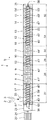
以下の説明は、図1〜図4を参照して本発明の第1の例示的な実施形態について言及する。多軸スクリュー機械1は、添加剤3が設けられるプラスチック材料2を加工するために使用される。スクリュー機械1は、搬送方向5に互いに前後に配置されかつケーシング部と称される複数のケーシング部分6〜15から形成されたケーシング4を有する。ケーシング部分6〜15は、ケーシング4を形成するようにフランジ(より詳細に図示せず)によって相互接続される。
The following description refers to a first exemplary embodiment of the present invention with reference to FIGS. The multi-screw machine 1 is used for processing a plastic material 2 on which an additive 3 is provided. The screw machine 1 has a casing 4 formed of a plurality of
ケーシング4において、2つの平行で相互侵入するケーシング孔16、17が形成され、これらの孔は、断面で見たときに水平の8の字形である。2つの処理要素軸18、19は、駆動モータ20によって関連した回転軸線21、22を中心とする回転のために駆動可能であるように、ケーシング孔16、17に同心円的に配置される。配分ギアボックス23は、処理要素軸18、19と駆動モータ20との間に配置され、この場合、クラッチ24が駆動モータ20と配分ギアボックス23との間に配置される。処理要素軸18、19は、回転軸線21、22を中心に同一の方向に、言い換えれば同一の回転方向25、26に駆動される。
In the casing 4, two parallel and interpenetrating casing holes 16, 17 are formed, these holes being in the shape of a horizontal 8 when viewed in cross section. The two
配分ギアボックス23の隣の第1のケーシング部分6に、ホッパの形態の材料入口33が配置され、この入口を通してプラスチック材料2、必要な場合、添加剤3がケーシング孔16、17に導入可能である。
A
スクリュー機械1は、入口区間27、溶融区間28、ガス抜き区間29、均質化区間30、搬送区間31及び圧力増大区間32を有し、これらの各々は、搬送方向5に互いに前後に配置される。ケーシング4の最後のケーシング部分15は、放出開口部36が設けられるアダプタプレート35によってシールされる。
The screw machine 1 has an
処理要素軸18、19は、軸37、38と、それらの軸にそれぞれ配置された処理要素39〜48又は39’〜48’とによって形成される。第1の軸37に配置された処理要素39〜48、及び第2の軸38に配置された処理要素39’〜48’は互いに対応し、この場合、第2の軸38に配置された処理要素39’〜48’の参照番号には、処理要素39〜48と区別するために「’」が付与されている。図1〜図4による例示的な実施形態では、処理要素39〜48及び39’〜48’は、各々、関連したケーシング部分6〜15の長さに対応する長さを有する。入口区間27では、処理要素は、スクリュー要素39〜40’として構成される。スクリュー要素39、39’及び40、40’は、互いに係合するように軸37、38に互いに隣に配置され、言い換えれば、それらは近接相互噛合対として構成される。スクリュー要素39、39’は、それぞれの第1のストッパ49、49’によって回転軸線21、22の方向に固定され、第1のストッパは、各々、軸37、38の上流端部に配置され、スクリュー要素39又は39’にそれぞれ当接する。第1のケーシング部分6は、2つのリードスルー孔51、51’が設けられる第1の閉鎖プレート50によって配分ギアボックス23の方向にシールされる。軸37、38は、端側リードスルー孔51、51’を通して導かれ、配分ギアボックス23に連結される。
The
溶融区間28では、第1の混練要素41、41’及び第2の混練要素42、42’の形態の処理要素が、軸37、38に配置される。混練要素41、41’及び42、42’はまた、近接相互噛合対を形成するように構成される。混練要素41〜42’の各々は、一部片を形成するように構成される。混練要素41〜42’は、各々、互いに角度オフセットして配置される5つの混練ディスクを有する。
In the
ガス抜き区間29では、近接相互噛合するスクリュー要素43、43’が軸37、38に配置される。スクリュー要素39〜40’に対応して、スクリュー要素43、43’は、各々、一部片を形成するように構成される。関連したケーシング部分10は、ガス抜き用のガス抜き開口部52を有する。
In the
均質化区間30の下流において、軸37、38に、各々が一部片を形成するように構成される近接相互噛合する混練要素44、44’が設けられる。次に、混練要素44、44’は、互いに角度オフセットして配置される混練ディスクから形成される。
Downstream of the
さらに、搬送区間31の下流において、軸37、38に、一部片を形成するように構成される近接相互噛合するスクリュー要素45、45’及び46、46’が設けられる。相応して、スクリュー要素47、47’及び48、48’が圧力増大区間の下流の軸37、38に配置される。
In addition, downstream of the conveying
処理要素39〜48’は、軸先端又はスクリュー先端53、53’によって通常の方法で軸37、38に固定される。軸先端53、53’は、スクリュー要素48、48’が当接するためのそれぞれの第2のストッパ54、54’を形成するために、軸先端53、53’用のそれぞれのスクリュー接続部によって軸37、38の端部に接続可能である。ストッパ49、49’及び54、54’によって、処理要素39〜48又は39’〜48’は、それぞれ、軸方向に軸37、38に固定される。
The
軸37、38は同一であり、したがって、以下の説明は軸37のみについて言及される。軸37は、第1の部分軸55と、搬送方向5に第1の部分軸の下流に配置された第2の部分軸56とを有し、部分軸55、56は、スクリュー接続部によって相互接続される。第1のストッパ49から開始して、第1の部分軸55は軸長L1を有し、一方、第2の部分軸56は第2のストッパ54までの軸長L2を有する。長さL1とL2の和は軸37の全長Lに等しい。全長Lは例えば10.0mである。
The
第1の部分軸55は、搬送区間31内まで延びて、スクリュー要素45の領域で終端するような軸長L1を有する。スクリュー要素45は、したがって、部分軸55、56の両方に重なり合うように軸37に回転しないように配置される。スクリュー要素45を重なり合うように配置するために、第1の部分軸55は第1の外側輪郭部A1を有し、第2の部分軸56は対応する第2の外側輪郭部A2を有し、これらの輪郭部は、部分軸55、56が相互接続されるときに、外側輪郭部A1とA2に対応する内側輪郭部Iを有するスクリュー要素45が2つの外側輪郭部A1とA2に回転しないように配置されるように互いに整列される。したがって、外側輪郭部A1とA2は、互いに面一であるように構成され、スクリュー要素45を、両方の部分軸55、56に実質的に遊びなしに取り付けるか又は位置決めすることを可能にする。
The first
スクリュー要素45の前の処理要素39〜44の対応する内側輪郭部Iは、非回転の接続が形成されるように第1の部分軸55の外側輪郭部A1に配置される。さらに、スクリュー要素45の背後のスクリュー要素46〜48の対応する内側輪郭部Iは、非回転の接続が形成されるように第2の部分軸56の外側輪郭部A2に配置される。好ましくは、処理要素39〜48の外側輪郭部A1とA2及びそれぞれの内側輪郭部Iは、インボリュート伝動装置を形成する。
The corresponding inner contour I of the
最高のトルクが溶融区間28の領域に生じるとき、1つ又は複数の第1の部分軸55は、それぞれ、溶融区間28を越えて延び、混練要素41、41’及び混練要素42、42’の両方が第1の部分軸55に配置されることを可能にする。
When the highest torque occurs in the region of the
スクリュー接続部57によって、部分軸55、56は、それぞれの軸37、38が間隙なしに又は実質的に間隙なしに形成されるように相互接続される。このために、第1の部分軸55に、回転軸線21に対して同心であるように下流前端に形成される接続孔58が設けられる。接続孔58に、雌ねじ59が形成される。これと対照的に、第2の部分軸56に、回転軸線21に対して同心であるように上流前端に形成される接続ピン60が設けられる。接続ピン60は、接続孔58の雌ねじ59の下方にねじ留めされるように適応される雄ねじ61が設けられる。スクリュー接続部57は、処理要素軸18、19が多軸スクリュー機械1の動作中にそれぞれの回転方向25、26に回転するときに、接続部が締まって、緩まないように構成される。
By means of a
軸37、38が間隙なしに形成されるように、部分軸55、56の前端は、共にねじ留めされるときに互いに当接する。処理要素39〜48又は39’〜48’は、それぞれ、軸方向の予荷重力FV、言い換えれば、それぞれの回転軸線21、22の方向に作用する予荷重力FVにより対応する軸37、38に配置される。処理要素39〜48又は39’〜48’は、それぞれ、したがって、予荷重力FVにより互いに押圧され、それぞれの軸37又は38が、対応する量の引張応力を受けるようにされる。予荷重力FVに応じて、小さな間隙が軸方向の部分軸55、56の間に形成され得る。予荷重力FVは、特に、FV≧50kN、特にFV≧100kN、特にFV≧150kNのような予荷重力である。
The front ends of the
軸37、38の部分軸56、57の材料、材料加工及び/又は長さは、加工作業に適応され、加工作業に応じて、これらの特徴は等しい及び/又は異なる。
The material, material processing and / or length of the
第2の長さL2に対する第1の長さL1の比率は、L1/L2≧1、特にL1/L2≧1.5、特にL1/L2≧2のような比率であることが好ましい。本発明による多軸スクリュー機械1の利点は、比較的長い軸37、38及び処理要素39〜48’の比較的大きな直径が使用される場合、特に明白である。好ましくは、軸37、38の各々は、L≧6.0m、特にL≧8.0、特にL≧10.0mが適用される全長Lを有する。さらに、直径、言い換えれば、ケーシング孔16、17の内径Dは、D≧177mm、特にD≧248mm、特にD≧315mm、特にD≧352mmのような内径であることが好ましい。
The ratio of the first length L 1 to the second length L 2 is such that L 1 / L 2 ≧ 1, in particular L 1 / L 2 ≧ 1.5, in particular L 1 / L 2 ≧ 2. It is preferable that The advantages of the multi-screw machine 1 according to the invention are particularly evident when relatively
以下の説明は、多軸スクリュー機械の組立及び動作について言及する。 The following description refers to the assembly and operation of a multi-screw machine.
処理要素軸18、19を製造するために、部分軸55、56は、対を形成するように最初は共にねじ留めされる。このために、各々の第2の部分軸56の接続ピン60のそれぞれの雄ねじ61が、関連した第1の部分軸55に形成された接続孔58の関連した雌ねじ59の下方にねじ留めされる。部分軸56は、外側輪郭部A1とA2が互いに面一であるように部分軸55にねじ留めされる。その後、処理要素39〜48又は39’〜48’は、それぞれ、予め規定された予荷重力FVにより軸37、38に取り付けられる。このために、スクリュー要素39又は39’は、それぞれ、第1の段階で軸37、38上を摺動し、それぞれの第1のストッパ49、49’まで移動される。その後、その他の処理要素40〜48又は40’〜48’は、それぞれ、それぞれの軸37、38上を連続して摺動する。最後に、軸先端53、53’は、処理要素39〜48又は39’〜48’がそれぞれ挟持されるように、それぞれの軸37、38に取り付けられる。このために、軸先端53、53’は、関連した第2の部分軸56の下流前端にねじ留めされ、処理要素39、48又は39’〜48’が、それぞれ、それぞれの第1のストッパ49、49’と、それぞれの第2のストッパ54、54’との間に挟持されるようにする。部分軸55、56の間のそれぞれの継手は、スクリュー要素45、45’それぞれが、部分軸55、56の両方に重なり合うように配置されるように配置される。多軸スクリュー機械1を組み立てるための残りの段階は、通常の方法で実施される。
In order to produce the
多軸スクリュー機械1の動作時、処理要素軸18、19は、同一の回転方向25、26の回転のために駆動モータ20によって駆動される。加工されるべきプラスチック材料2及び添加剤3は、材料入口33を介してケーシング孔16、17に導入され、搬送方向5に入口区間27に沿って、溶融区間28まで移送される。
During operation of the multi-axis screw machine 1, the
溶融区間28では、プラスチック材料2は、混練要素41、42又は41’、42’それぞれによって加えられる高い機械的エネルギーを受け、プラスチック材料2の溶融を引き起こす。この結果、したがって、最高のトルクが溶融区間28に、特に混練要素41、41’の領域に生じる。これらのトルクは、通常の方法で一体の部分軸55を介して混練要素41、42又は41’、42’それぞれに伝達される。
In the
隣接するガス抜き区間29では、溶融物は、ガス抜きされて、均質化区間30に搬送され、この区間で、溶融物及びその中に含有された添加剤3がさらに均質化される。
In the
隣接する搬送区間31では、溶融物が圧力増大区間32の方向に搬送される前に、他の均質化工程が行われる。スクリュー要素45、45’が部分軸55、56の両方に重なり合うように配置されるので、確実なトルク伝達が継手の領域で行われる。圧力増大区間32では、溶融物の圧力が、溶融物が放出開口部36を介して放出される前に増大される。
In the
多軸スクリュー機械1の動作時、温度上昇により、軸37、38が軸方向に膨張させられる。軸方向に互いに挟持されるように、処理要素39〜48又は39’〜48’それぞれに加えられる予荷重力FVにより、軸37、38に挟持された処理要素39〜48又は39’〜48’が、軸37、38の軸方向膨張の結果として軸方向に緩むことが防止される。
During the operation of the multi-screw machine 1, the
軸37、38の各々が、各々2つの部分軸55、56から製造されるという事実によって、部分軸55、56の材料、材料加工及び/又は長さを加工作業に最適に適応させることができる。この結果、部分軸55、56の材料、材料加工及び/又は長さは、要件に従って等しい及び/又は異なるように選択することができ、一定量の機能性及び信頼性を確実にしつつ、製造コストの低減を可能にする。
Due to the fact that each of the
以下の説明は、図5及び図6を参照して本発明の第2の例示的な実施形態について言及する。第1の例示的な実施形態と対照的に、軸37、38は、各々、3つの相互接続された部分軸55、56と62から製造される。第1の部分軸55はガス抜き区画29内まで延び、その結果、スクリュー要素43、43’は、第1の部分軸55及び各々第1の部分軸に接続される第2の部分軸56の両方に重なり合うように配置される。このために、部分軸55、56の外側輪郭部A1とA2は、上述の方法で互いに整列される。スクリュー接続部57は、第1の例示的な実施形態のスクリュー接続部に対応する。
The following description refers to a second exemplary embodiment of the present invention with reference to FIGS. In contrast to the first exemplary embodiment, the
第3の部分軸62の各々は、部分軸56、62が相互接続されるときにそれぞれの外側輪郭部A2と面一である外側輪郭部A3を有する。第2の部分軸62は搬送区画31内まで延び、その結果、スクリュー要素46、46’は、相互接続された部分軸56、62に重なり合うように配置される。部分軸56、62は、部分軸55、56のスクリュー接続部57に対応するスクリュー接続部57によって相互接続される。
Each of the
回転軸線21、22の方向に、第3の部分軸62は、第2の部分軸56の長さL2に好ましくは等しい長さL3を有する。長さL1は、長さL2又はL3それぞれよりも大きいことが好ましく、その結果、第1の部分軸55は、特に混練要素41、41’が第1の部分軸55に配置されるように溶融区間28を越えて延びる。
In the direction of the
処理要素軸18、19の組立及び多軸スクリュー機械1の動作に関する詳細は、第1の例示的な実施形態の説明に確認することができる。
Details regarding the assembly of the
以下の説明は、図7を参照して本発明の第3の例示的な実施形態について言及する。前述の例示的な実施形態と対照的に、環状座金63は、各々、相互接続された部分軸55、56の間に配置される。それぞれの第2の部分軸56の接続ピン60は、部分軸55、56が相互接続されるときに、座金63が部分軸55、56の前端に当接するように、座金63のリードスルー開口部64を通して導かれる。前述の例示的な実施形態に対応して、処理要素39〜48又は39’〜48’は、それぞれ、予荷重力FVによる予荷重を受ける。予荷重力FVに応じて、小さな間隙が、座金63と、隣接する部分軸55、56の一方又は隣接する部分軸55、56との間に生じ得る。座金63は、第1の部分軸55の熱膨張係数α1及び第2の部分軸56の熱膨張係数α2の少なくとも一方よりも大きい軸方向の熱膨張係数αSを有する。好ましくは、熱膨張係数αSは、両方の熱膨張係数α1とα2よりも大きい。座金63は、関連した回転軸線21又は22それぞれに対して実質的に同心であり、外側輪郭部A1とA2によって画定されたそれぞれの軸37、38の軸直径よりも小さい直径を有する。
The following description refers to a third exemplary embodiment of the present invention with reference to FIG. In contrast to the exemplary embodiment described above, the
熱膨張係数α1の少なくとも一方に対する熱膨張係数αSの比率は、αS/αi≧1.5、特にαS/αi≧2、特にαS/αi≧2.5のような比率であり、この場合i=1又は2。好ましくは、上記の比率は、i=1及び2によりαS/αiに適用される。 The ratio of the thermal expansion coefficient α S to at least one of the thermal expansion coefficients α 1 is such that α S / α i ≧ 1.5, in particular α S / α i ≧ 2, in particular α S / α i ≧ 2.5. Ratio, where i = 1 or 2. Preferably, the above ratio applies to α S / α i with i = 1 and 2.
熱膨張係数αSは、αS≧12.0・10−61/K、特にαS≧15.0・10−61/K、特にαS≧18.0・10−61/Kのような熱膨張係数であることが好ましい。 The coefficient of thermal expansion α S is α S ≧ 12.0 · 10 −6 1 / K, in particular α S ≧ 15.0 · 10 −6 1 / K, in particular α S ≧ 18.0 · 10 −6 1 / K. It is preferable that the coefficient of thermal expansion be as follows.
座金63は、それぞれの回転軸線21、22の方向に寸法LSを有し、この場合、寸法LSは、5mm≦LS≦50mm、特に10mm≦LS≦40mm、特に15mm≦LS≦30mmのような寸法であることが好ましい。
The
部分軸55、56が共にねじ留めされる前に、それぞれの座金63がそれらの間に配置される。熱膨張係数αSは、熱膨張係数α1又はα2の少なくとも一方よりもそれぞれ大きく、好ましくは両方の熱膨張係数α1とα2よりも大きいという事実によって、多軸スクリュー機械1の動作時の温度上昇による軸方向の膨張の場合にも、それぞれの軸37、38には間隙がないままであるか、あるいは座金63と、部分軸55、56の一方又は部分軸55、56との間の可能な間隙が、軸方向の座金63の比較的大きな膨張の結果閉じられ、それぞれの軸37、38の間隙を消えさせる。加熱動作条件では、したがって、軸37、38には間隙がなく、このように、それぞれストッパ49と54又は49’と54’との間の確実なトルク伝達及び処理要素39〜48又は39’〜48’のしっかりした軸方向の取付けがそれぞれ確実にされる。加熱動作条件では、軸37、38は、少なくとも100℃、特に少なくとも150℃、特に少なくとも200℃の温度を有する。
Before the
第2の実施形態に対応して、軸37、38が3つの部分軸55、56と62から構成される場合、座金63は、相互接続された部分軸55、56及び56と62の間に配置され、この場合、それらの熱膨張係数αSは、隣接する部分軸55、56又は56、62のそれぞれ1つの熱膨張係数α1又はα2及びα2又はα3よりもそれぞれ大きい。好ましくは、座金63は同一である。3つの部分軸55、56と62を備える軸37、38の場合、熱膨張係数はαiと称され、この場合i=1,2,3。処理要素軸18、19のさらなる組立及び多軸スクリュー機械1の動作に関する詳細は、前述の例示的な実施形態の説明に確認することができる。
Corresponding to the second embodiment, if the
以下の説明は、図8を参照して本発明の第4の例示的な実施形態について言及する。前述の例示的な実施形態と対照的に、部分軸55、56の間に配置されたそれぞれの座金63は、外側輪郭部A1とA2に対応して構成されかつ整列される外側座金輪郭部ASを有する。それぞれのスクリュー要素45、45’の内側輪郭部Iは、したがって、外側輪郭部A1、ASとA2に重なり合うように配置される。この結果、それぞれのスクリュー要素45、45’は、部分軸55、56及びそれらの間に配置された座金63に回転しないように接続される。これにより、確実なトルク伝達が確実にされる。軸37、38が3つの部分軸55、56と62から構成される場合、第3の実施形態に関する説明が、輪郭付き座金63又は複数の輪郭付き座金にそれぞれ適用される。
The following description refers to a fourth exemplary embodiment of the present invention with reference to FIG. In contrast to the previous exemplary embodiment, each
処理要素軸18、19のさらなる組立及び多軸スクリュー機械1のさらなる動作に関する詳細は、前述の実施形態の説明に確認することができる。
Details regarding further assembly of the
1 多軸スクリュー機械
2 プラスチック材料
3 添加剤
4 ケーシング
5 搬送方向
6〜15 ケーシング部分
16、17 ケーシング孔
18、19 処理要素軸
20 駆動モータ
21、22 回転軸線
23 配分ギアボックス
24 クラッチ
25、26 回転方向
27 入口区間
28 溶融区間
29 ガス抜き区間
30 均質化区間
31 搬送区間
32 圧力増大区間
33 材料入口
35 アダプタプレート
36 放出開口部
37 第1の軸
38 第2の軸
39〜48 処理要素
39’〜48’ 処理要素
49、49’ 第1のストッパ
50 第1の閉鎖プレート
51、51’ 端側リードスルー孔
52 ガス抜き開口部
53、53’ 軸先端又はスクリュー先端
54、54’ 第2のストッパ
55 第1の部分軸
56 第2の部分軸
57 スクリュー接続部
58 接続孔
59 雌ねじ
60 接続ピン
61 雄ねじ
62 第3の部分軸
63 環状座金
64 リードスルー開口部
A1 第1の外側輪郭部
A2 第2の外側輪郭部
AS 外側座金輪郭部
D 内径
FV 軸方向の予荷重力
I 内側輪郭部
L 全長
L1 軸長
L2 軸長
LS 寸法
α1 熱膨張係数
α2 熱膨張係数
α3 熱膨張係数
αS 熱膨張係数
DESCRIPTION OF SYMBOLS 1 Multiaxial screw machine 2 Plastic material 3 Additive 4
Claims (14)
前記第1の部分軸(55)が各々、少なくとも溶融区間(28)まで延び、また前記第1の部分軸(55)の各々に少なくとも1つの混練要素(41、41’)が回転不能に配置されることを特徴とする多軸スクリュー機械。 Material, in particular plastic material, comprising a casing (4), at least two casing holes (16, 17) formed in the casing (4) and at least two processing element shafts (18, 19) A multi-screw machine for driving, wherein said at least two processing element shafts are arranged in associated casing holes (16, 17) and can be driven for rotation about associated rotational axes (21, 22) Comprising a plurality of processing elements (39-48, 39′-48 ′) for processing the material (2, 3) to be processed, said plurality of processing elements being each rotating axis (21, 22) in a non-rotatable manner in at least two related axes (37, 38) one after the other in the direction of 22), said at least two axes (37, 38) each being a first partial axis (55); Small At least one second partial axis (56; 56, 62), said partial axes (55, 56; 55, 56, 62) being interconnected to form respective axes (37, 38). , Processing elements (45, 45 ′; 43, 43), which are non-rotatably arranged on each of the axes (37, 38) so as to overlap the interconnected partial axes (55, 56; 55, 56, 62). 43 ', 46, 46') in a multi-screw machine,
Each of the first partial shafts (55) extends at least to the melting section (28), and at least one kneading element (41, 41 ′) is non-rotatably disposed on each of the first partial shafts (55). A multi-screw machine characterized by being made.
前記重なり合う処理要素(45、45’;43、43’、46、46’)の内側輪郭部(I)が両方の外側輪郭部(A1、A2;A1、A2、A3)に回転不能に配置されるように、前記相互接続された部分軸(55、56)の前記外側輪郭部(A1、A2;A1、A2、A3)が互いに一列に整列されることを特徴とする、請求項1に記載の多軸スクリュー機械。 Each of the interconnected partial axes (55, 56; 55, 56, 62) comprises an outer contour (A 1 , A 2 ; A 1 , A 2 , A 3 );
The inner contours (I) of the overlapping processing elements (45, 45 ′; 43, 43 ′, 46, 46 ′) are in both outer contours (A 1 , A 2 ; A 1 , A 2 , A 3 ). The outer contours (A 1 , A 2 ; A 1 , A 2 , A 3 ) of the interconnected partial axes (55, 56) are aligned with each other so as to be non-rotatable The multi-screw machine according to claim 1, wherein:
Each of said shaft said portion axis (37, 38) (55, 56; 55,56,62), wherein the benzalkonium interconnected by a screw connection (57), of claim 1 to 5 The multi-axis screw machine as described in any one of Claims.
Applications Claiming Priority (2)
| Application Number | Priority Date | Filing Date | Title |
|---|---|---|---|
| EP13168549.7A EP2805805B1 (en) | 2013-05-21 | 2013-05-21 | Multiple shaft machine for the treatment of materials, in particular plastic materials |
| EP13168549.7 | 2013-05-21 |
Publications (2)
| Publication Number | Publication Date |
|---|---|
| JP2014226937A JP2014226937A (en) | 2014-12-08 |
| JP6298708B2 true JP6298708B2 (en) | 2018-03-20 |
Family
ID=48444245
Family Applications (1)
| Application Number | Title | Priority Date | Filing Date |
|---|---|---|---|
| JP2014102168A Active JP6298708B2 (en) | 2013-05-21 | 2014-05-16 | Multi-axis screw machine for processing materials |
Country Status (4)
| Country | Link |
|---|---|
| EP (1) | EP2805805B1 (en) |
| JP (1) | JP6298708B2 (en) |
| CN (1) | CN104175527B (en) |
| ES (1) | ES2719324T3 (en) |
Families Citing this family (2)
| Publication number | Priority date | Publication date | Assignee | Title |
|---|---|---|---|---|
| JP2016199440A (en) * | 2015-04-13 | 2016-12-01 | 住友金属鉱山株式会社 | Crystal growth apparatus |
| DE102016219801B4 (en) * | 2016-10-12 | 2019-08-22 | Coperion Gmbh | Coupling device for connecting a transmission output shaft and a worm shaft of a screw machine and worm gear assembly with such a coupling device and method for connecting and disconnecting a transmission output shaft and a worm shaft of a screw machine |
Family Cites Families (14)
| Publication number | Priority date | Publication date | Assignee | Title |
|---|---|---|---|---|
| NL131340C (en) * | 1963-11-27 | 1900-01-01 | ||
| FR2472970A1 (en) * | 1980-01-04 | 1981-07-10 | Saint Marcel Mfg | Multi-piece extrusion screw with self-tightening segment couplings - for assembly of selective replacement of complex screw profiles |
| US4447156A (en) * | 1981-08-31 | 1984-05-08 | Northern Lights Trust | Modular mixing apparatus including interchangeable fluid processing means |
| JPS5881146A (en) * | 1981-11-09 | 1983-05-16 | Mitsubishi Heavy Ind Ltd | Extrusion screw |
| DE3940954A1 (en) * | 1989-12-12 | 1991-06-13 | Battenfeld Extrusionstech | Extruder screw for efficient mixing - has start and end parts with concentric circular core profiles but asymmetrical intermediate length which is pref. polygonal |
| DE4421514C2 (en) | 1994-06-20 | 1998-08-13 | Krupp Werner & Pfleiderer Gmbh | Screw machine with attachable screw set elements |
| JPH08309827A (en) * | 1995-05-23 | 1996-11-26 | Japan Steel Works Ltd:The | Segment screw |
| JP3434418B2 (en) * | 1996-07-24 | 2003-08-11 | 東芝機械株式会社 | High-melting point resin dewatering system with co-rotating twin screw extruder |
| DE102004052055B4 (en) * | 2004-10-26 | 2014-11-20 | Blach Verwaltung Gmbh & Co.Kg | extruder |
| JP4083183B2 (en) * | 2005-06-27 | 2008-04-30 | 株式会社日本製鋼所 | Screw for kneading extruder |
| DE202007008072U1 (en) * | 2007-06-08 | 2008-10-23 | Hasenbein, Günter, Dipl.-Ing. | Snail of a screw press |
| US20090258100A1 (en) * | 2008-04-10 | 2009-10-15 | Good Earth Tools, Inc. | Thermal Growth Compensating Extrusion Screw Assembly |
| JP5645480B2 (en) * | 2010-05-26 | 2014-12-24 | 川崎三興化成株式会社 | Vent device for twin screw extruder |
| CN202318878U (en) * | 2011-11-10 | 2012-07-11 | 上海金昌工程塑料有限公司 | Screw rod assembly of double-screw extruder |
-
2013
- 2013-05-21 EP EP13168549.7A patent/EP2805805B1/en active Active
- 2013-05-21 ES ES13168549T patent/ES2719324T3/en active Active
-
2014
- 2014-05-15 CN CN201410205404.4A patent/CN104175527B/en active Active
- 2014-05-16 JP JP2014102168A patent/JP6298708B2/en active Active
Also Published As
| Publication number | Publication date |
|---|---|
| CN104175527B (en) | 2017-07-14 |
| JP2014226937A (en) | 2014-12-08 |
| CN104175527A (en) | 2014-12-03 |
| EP2805805A1 (en) | 2014-11-26 |
| ES2719324T3 (en) | 2019-07-09 |
| EP2805805B1 (en) | 2019-02-27 |
Similar Documents
| Publication | Publication Date | Title |
|---|---|---|
| US9061442B2 (en) | Extruder | |
| JP4126295B2 (en) | Screw type extruder | |
| JP5167266B2 (en) | Multi-screw extruder | |
| CN101300120B (en) | Multi-screw extruder | |
| JP6298708B2 (en) | Multi-axis screw machine for processing materials | |
| JP5683457B2 (en) | Multi-screw extruder | |
| US4527899A (en) | Processing shaft for machines for extruding, kneading, dispersing, mixing or homogenizing, in particular, plastics materials | |
| CN107664162B (en) | Connecting system for connecting shaft, hub, sleeve or the like to gear comprising helical drive portion | |
| KR101597502B1 (en) | Single-shaft eccentric screw pump | |
| RU2354553C2 (en) | Extruder auger | |
| JP2008511469A (en) | Extruder worm | |
| US20140208880A1 (en) | Gear Wheel Having Helical Toothing and Segment for a Gear Wheel | |
| US20140270921A1 (en) | Hybrid torque transmission mechanism | |
| US11543011B2 (en) | Multi-piece gearwheel and gearbox for a steering system | |
| JP5586193B2 (en) | Extrusion equipment | |
| US9056292B2 (en) | Barrel alignment in extruder systems | |
| KR101676282B1 (en) | segment type coupling using composite material | |
| WO2010109486A1 (en) | A safety device in torque transmission system | |
| JP4083183B2 (en) | Screw for kneading extruder | |
| US8167478B2 (en) | Kneading screw and extruder | |
| KR101979737B1 (en) | Spline shaft and spline manufacturing method | |
| JP5173009B1 (en) | Material supply equipment for injection molding machines | |
| WO2022138035A1 (en) | Screw machine | |
| JP3867974B2 (en) | Split-type rotor of screw kneading extruder | |
| JP2024022510A (en) | Processing elements for processing materials using screw machines |
Legal Events
| Date | Code | Title | Description |
|---|---|---|---|
| A621 | Written request for application examination |
Free format text: JAPANESE INTERMEDIATE CODE: A621 Effective date: 20161221 |
|
| A131 | Notification of reasons for refusal |
Free format text: JAPANESE INTERMEDIATE CODE: A131 Effective date: 20171114 |
|
| A521 | Request for written amendment filed |
Free format text: JAPANESE INTERMEDIATE CODE: A523 Effective date: 20180117 |
|
| TRDD | Decision of grant or rejection written | ||
| A01 | Written decision to grant a patent or to grant a registration (utility model) |
Free format text: JAPANESE INTERMEDIATE CODE: A01 Effective date: 20180130 |
|
| A61 | First payment of annual fees (during grant procedure) |
Free format text: JAPANESE INTERMEDIATE CODE: A61 Effective date: 20180226 |
|
| R150 | Certificate of patent or registration of utility model |
Ref document number: 6298708 Country of ref document: JP Free format text: JAPANESE INTERMEDIATE CODE: R150 |
|
| R250 | Receipt of annual fees |
Free format text: JAPANESE INTERMEDIATE CODE: R250 |
|
| R250 | Receipt of annual fees |
Free format text: JAPANESE INTERMEDIATE CODE: R250 |
|
| R250 | Receipt of annual fees |
Free format text: JAPANESE INTERMEDIATE CODE: R250 |
|
| R250 | Receipt of annual fees |
Free format text: JAPANESE INTERMEDIATE CODE: R250 |