JP6296819B2 - Liquid discharge head and liquid discharge apparatus - Google Patents
Liquid discharge head and liquid discharge apparatus Download PDFInfo
- Publication number
- JP6296819B2 JP6296819B2 JP2014027713A JP2014027713A JP6296819B2 JP 6296819 B2 JP6296819 B2 JP 6296819B2 JP 2014027713 A JP2014027713 A JP 2014027713A JP 2014027713 A JP2014027713 A JP 2014027713A JP 6296819 B2 JP6296819 B2 JP 6296819B2
- Authority
- JP
- Japan
- Prior art keywords
- liquid
- suction
- droplet
- suction tube
- inner diameter
- Prior art date
- Legal status (The legal status is an assumption and is not a legal conclusion. Google has not performed a legal analysis and makes no representation as to the accuracy of the status listed.)
- Active
Links
Images


Classifications
-
- B—PERFORMING OPERATIONS; TRANSPORTING
- B41—PRINTING; LINING MACHINES; TYPEWRITERS; STAMPS
- B41J—TYPEWRITERS; SELECTIVE PRINTING MECHANISMS, i.e. MECHANISMS PRINTING OTHERWISE THAN FROM A FORME; CORRECTION OF TYPOGRAPHICAL ERRORS
- B41J2/00—Typewriters or selective printing mechanisms characterised by the printing or marking process for which they are designed
- B41J2/005—Typewriters or selective printing mechanisms characterised by the printing or marking process for which they are designed characterised by bringing liquid or particles selectively into contact with a printing material
- B41J2/01—Ink jet
- B41J2/17—Ink jet characterised by ink handling
- B41J2/1721—Collecting waste ink; Collectors therefor
-
- B—PERFORMING OPERATIONS; TRANSPORTING
- B41—PRINTING; LINING MACHINES; TYPEWRITERS; STAMPS
- B41J—TYPEWRITERS; SELECTIVE PRINTING MECHANISMS, i.e. MECHANISMS PRINTING OTHERWISE THAN FROM A FORME; CORRECTION OF TYPOGRAPHICAL ERRORS
- B41J2/00—Typewriters or selective printing mechanisms characterised by the printing or marking process for which they are designed
- B41J2/005—Typewriters or selective printing mechanisms characterised by the printing or marking process for which they are designed characterised by bringing liquid or particles selectively into contact with a printing material
- B41J2/01—Ink jet
- B41J2/17—Ink jet characterised by ink handling
- B41J2/1714—Conditioning of the outside of ink supply systems, e.g. inkjet collector cleaning, ink mist removal
-
- B—PERFORMING OPERATIONS; TRANSPORTING
- B41—PRINTING; LINING MACHINES; TYPEWRITERS; STAMPS
- B41J—TYPEWRITERS; SELECTIVE PRINTING MECHANISMS, i.e. MECHANISMS PRINTING OTHERWISE THAN FROM A FORME; CORRECTION OF TYPOGRAPHICAL ERRORS
- B41J2/00—Typewriters or selective printing mechanisms characterised by the printing or marking process for which they are designed
- B41J2/005—Typewriters or selective printing mechanisms characterised by the printing or marking process for which they are designed characterised by bringing liquid or particles selectively into contact with a printing material
- B41J2/01—Ink jet
- B41J2/17—Ink jet characterised by ink handling
- B41J2/1721—Collecting waste ink; Collectors therefor
- B41J2002/1728—Closed waste ink collector
Description
本発明は、液体ジェット方式に従って液体を吐出して記録媒体に記録を行う液体吐出ヘッドとそれを有する液体吐出装置に関する。特に、液体吐出口面に液体滴が付着したり滴下したりするのを回避するために設けられた液体吸引管の適正化に関する。 The present invention relates to a liquid discharge head that discharges liquid according to a liquid jet method and performs recording on a recording medium, and a liquid discharge apparatus having the liquid discharge head. In particular, the present invention relates to the optimization of a liquid suction tube provided to avoid liquid droplets adhering to or dropping from the liquid discharge port surface.
液体を吐出して記録媒体に画像を記録する液体吐出装置では、液体吐出ヘッドと記録媒体の間において、主滴よりも小さな副滴や記録媒体の表面で跳ね返った微細な液体滴(ミスト)が浮遊し、装置内部の様々な機材を汚染してしまう場合がある。そして、例えば、搬送される記録媒体を表面から抑えるピンチローラにミストが付着した場合は、ローラの回転に伴って画像とは無関係な液体が記録媒体に転写してしまうことがある。また、液体吐出ヘッドの吐出口近傍にミストが付着して乾燥した場合は、その固着物によって吐出口が塞がれ、正常な吐出が実行できずに画像品位を損なうおそれもある。 In a liquid ejecting apparatus that ejects liquid and records an image on a recording medium, a sub-droplet smaller than the main droplet or a fine liquid droplet (mist) bounced off the surface of the recording medium is formed between the liquid ejecting head and the recording medium. It may float and contaminate various equipment inside the device. For example, when mist adheres to a pinch roller that holds the conveyed recording medium from the surface, liquid unrelated to the image may be transferred to the recording medium as the roller rotates. Further, when mist adheres to the vicinity of the discharge port of the liquid discharge head and is dried, the discharge port is blocked by the fixed matter, and normal discharge cannot be performed, which may impair image quality.
これに対し、例えば特許文献1や特許文献2には、液体吐出ヘッドの近傍にエア吸引口を設け、エアとともに浮遊するミストを吸入する構成が開示されている。特許文献1や特許文献2のような構成であれば、液体吐出ヘッドと記録媒体との間に浮遊するミストを効果的に除去し、ミストによる画像汚染を抑制することが出来る。 On the other hand, for example, Patent Document 1 and Patent Document 2 disclose a configuration in which an air suction port is provided in the vicinity of the liquid discharge head, and mist floating with air is sucked. If it is the structure like patent document 1 or patent document 2, the mist which floats between a liquid discharge head and a recording medium can be removed effectively, and the image contamination by mist can be suppressed.
しかしながら、吸引口から一度吸引されても、その経路中でミストが結合して大きな液滴を形成すると、そのミスト集合体が吸引口から落下して記録媒体や装置内部を汚染する場合がある。 However, even if the mist is once sucked from the suction port, if the mist is combined in the path to form a large droplet, the mist aggregate may fall from the suction port and contaminate the recording medium or the inside of the apparatus.
本発明は上記問題点を解決するために成されたものであり、その目的とするところは、一度吸引口より吸引されたミストが再び吸引口に戻るのを回避することが可能な吸引管を備えた液体吐出ヘッドを提供することである。 The present invention has been made to solve the above-described problems, and an object of the present invention is to provide a suction tube capable of avoiding that mist once sucked from the suction port returns to the suction port again. It is to provide a liquid discharge head provided.
そのために本発明は、液体を吐出する複数の吐出口と液体ミストを含む大気を吸入する吸引口とが設けられた面と、前記吸引口から吸入された液体ミストを通過させるための吸引管と、を備える液体吐出ヘッドであって、前記吸引管の内径Lは、液体の密度をρ、重力加速度をg、円周率をπ、液体と前記吸引管の内壁の間の界面エネルギをγLV、としたとき、
L≦(1/2)・{(12・γ・LV/(ρ・g・π)}^(1/2)
を満たすことを特徴とする。
Therefore, the present invention provides a surface provided with a plurality of discharge ports for discharging liquid and a suction port for sucking air including liquid mist, and a suction tube for allowing the liquid mist sucked from the suction port to pass therethrough. The suction pipe has an inner diameter L, the density of the liquid is ρ, the gravitational acceleration is g, the circumference is π, and the interface energy between the liquid and the inner wall of the suction pipe is γLV, When
L ≦ (1/2) · {(12 · γ · LV / (ρ · g · π)} ^ (1/2)
It is characterized by satisfying.
本発明によれば、吸引管の内部において液滴が滴下する大きさに成長する前にメニスカスが形成されるので、一度ガス吸引口より吸引されたミストが再びガス吸引口に戻るのを回避することが可能となる。 According to the present invention, since a meniscus is formed before the droplet grows to the size of dropping inside the suction tube, the mist once sucked from the gas suction port is prevented from returning to the gas suction port again. It becomes possible.
(実施例1)
図1(a)および(b)は、本実施例のインクジェット記録装置に代表される液体吐出装置が用いる液体吐出ヘッドの吐出口形成面10の平面図およびA−A´の断面図を示す図である。液体吐出ヘッドは、画像データに応じて個々のノズルからインク等の液体を吐出し、記録媒体に画像を記録する。ここでは、3列のノズル列81〜83とガス吸引口71〜73が備えられた液体吐出ヘッドを示している。
Example 1
FIGS. 1A and 1B are a plan view of a discharge
ノズル列81〜83の夫々はY方向に配列する複数の吐出口4を有し、これら複数の吐出口4に続く発泡室13には、共通する供給室6から供給路5を介して液体が供給される。個々の吐出口に対応する位置にはヒータ1が配備されており、このヒータ1が記録信号に応じて駆動されることにより、発泡室内にて液体の膜沸騰が生じ、生成された泡の成長エネルギによって液体が滴として吐出口から吐出される。液体吐出ヘッドの背後には不図示のガス吸引装置が配備され、吐出口近傍の空気やミストはノズル列の側部に配備されたガス吸引口71から矢印の方向に吸入される。
Each of the
図2は、液体吐出ヘッド2に対する液体の供給とガス吸入のシステムを示す図である。ここでは簡単のため、1組のノズル列82とガス吸引口72について示している。液体供給装置13には液体供給管12が接続され、液体供給管12は図1(b)で説明した供給室6に連結している。このような構成により、液体供給装置13に収容されている液体が、ノズル列82に備えられた複数のノズルに共通して液体を供給するようになっている。
FIG. 2 is a diagram showing a liquid supply and gas suction system for the liquid discharge head 2. Here, for simplicity, only one set of
一方、ガス吸引装置15には吸引管14が接続されており、吸引管14は液体吐出ヘッドの吐出口形成面10にて開口するガス吸引口72まで延在している。ガス吸引装置15はその内部で負圧を発生することが出来、この負圧に伴ってガス吸引口72から大気が吸入される。この際、吐出口4より吐出された正規の液体滴はガス吸い込み口7から吸引されることはないが、吐出口形成面10の近傍に浮遊している微細なミストはガス吸い込み口7から吸入される。液体ミストを通過させるための吸引管14の途中には、ガスとミストとを分類するためのミスト回収用チャンバーが設けられていても良い。また、ミストの回収量によらずガスの吸引量を一定に保つため、吸引されたミストの量に応じてガス吸引装置15の吸引力を調整するための弁などを用意しても良い。吸引管14およびガス吸い込み口7についての詳細な構造については後に詳しく説明する。
On the other hand, a
図3は、吸引管14の内壁に付着した液体液滴に作用する力の関係を示す図である。吸引管14に吸引されたミスト一部は、その内壁に付着しながらも互いの表面張力などによって集合し、液体液滴Dを形成する。ここで、水平面に対する内壁面の角度をα、液滴Dの重力方向の前進接触角をθa、後退接触角をθr、液滴Dの直径(接触面径)をW、質量をm、液滴Dと内壁の間の界面エネルギをγLV、重力加速度をgとする。この場合、液滴Dに作用する力の関係は、Furmidge式により(式1)によって表すことが出来る。C.G.L.Furmidge;J.Colloid Sci.17,309(1962)
m・g・sinα=W・γLV・(cosθr−cosθa) ・・・(式1)
FIG. 3 is a diagram showing the relationship between the forces acting on the liquid droplets attached to the inner wall of the
m · g · sin α = W · γLV · (cos θr−cos θa) (Formula 1)
式1における左辺が右辺よりも小さい場合、すなわち
m・g・sinα/{W・γLV・(cosθr−cosθa)}≦1の場合、液滴は内壁表面に停止している状態となる。
When the left side in Formula 1 is smaller than the right side, that is, when m · g · sin α / {W · γLV · (cos θr−cos θa)} ≦ 1, the droplet is stopped on the inner wall surface.
一方、左辺が右辺よりも大きい場合、すなわちm・g・sinα/{W・γLV・(cosθr−cosθa)}>1の場合、液滴は内壁内を下方に移動する状態となる。 On the other hand, when the left side is larger than the right side, that is, when m · g · sin α / {W · γLV · (cos θr−cos θa)}> 1, the liquid droplet moves downward in the inner wall.
例えば、α=90°、θa=90°、θr=0°の場合を考えると(式1)は、
m・g=W・γLV となる。
For example, considering the case of α = 90 °, θa = 90 °, θr = 0 °, (Equation 1) is
m · g = W · γLV
一方、液滴D自体を半球であると仮定し液体の密度をρ、円周率をπとすると、液滴の質量mは、m=(ρ・π・W^3)/12で表すことが出来るので、上記条件において、重力方向に移動を開始する際の液滴Dの直径Wは、(式2)によって表すことが出来る。
W={(12・γ・LV/(ρ・g・π)}^(1/2) ・・・(式2)
On the other hand, assuming that the droplet D itself is a hemisphere, and the density of the liquid is ρ and the circumference is π, the mass m of the droplet is expressed as m = (ρ · π · W ^ 3) / 12. Therefore, under the above conditions, the diameter W of the droplet D when starting to move in the direction of gravity can be expressed by (Expression 2).
W = {(12 · γ · LV / (ρ · g · π)} ^ (1/2) (Expression 2)
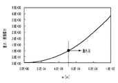
図4は、γLv=0.004N/mとした場合の、液滴Dの直径Wに対する式1の(左辺/右辺)を示した図である。縦軸の値が1を超える、すなわち液滴Dの直径Wが500μmを超えると、液滴Dに対する重力が壁面に止まろうとする表面張力より大きくなるため、液滴Dは、下方に移動する。このように、液滴Dが移動を開始するタイミングはその大きさ(直径)に依存する。 FIG. 4 is a diagram showing (left side / right side) of Equation 1 with respect to the diameter W of the droplet D when γLv = 0.004 N / m. When the value of the vertical axis exceeds 1, that is, the diameter W of the droplet D exceeds 500 μm, the gravity with respect to the droplet D becomes larger than the surface tension to stop on the wall surface, so the droplet D moves downward. Thus, the timing at which the droplet D starts to move depends on its size (diameter).
但し、液滴Dが移動を開始するための大きさに成長する前に、吸引管の中で液滴Dがメニスカスを形成すれば、界面エネルギγLVはメニスカス(液滴)の全周囲に渡って作用することになる。すなわち、式1における力の釣り合いは、(式3)で表すことが出来る。
m・g・sinα=W・π・γLV・(cosθr−cosθa)・・・(式3)
例えば、図4の例では、図3を参照するに、液滴Dの直径Wが500μmを超える前に液滴Dの頂点Pが吸引管14の内壁の対面に接触すれば、即ち吸引管14の内径が250μm以下であれば、液滴Dが下降する前に吸引管内にメニスカスMを形成することが出来る。
However, if the droplet D forms a meniscus in the suction tube before the droplet D grows to a size for starting movement, the interface energy γLV is spread over the entire circumference of the meniscus (droplet). Will work. That is, the balance of force in Equation 1 can be expressed by (Equation 3).
m · g · sin α = W · π · γLV · (cos θr−cos θa) (Formula 3)
For example, in the example of FIG. 4, referring to FIG. 3, if the apex P of the droplet D contacts the opposite surface of the inner wall of the
図5(a)および(b)は、吸引管14内にメニスカスMが形成された状態を示す図である。メニスカスMの形状は、ガス吸引装置15方向の内圧に応じて、図5(a)および(b)のいずれかになる。このようなメニスカスMが形成されると、メニスカス自体が吸引管内の大気の連通を妨げる状態となり、ガス吸引装置15の吸引力がメニスカスMに効果的に作用し、ミストが確実に吸引されることが期待出来る。
FIGS. 5A and 5B are views showing a state in which a meniscus M is formed in the
メニスカスが移動を開始するとき、吸引管14の管内の断面積をS、メニスカスMより分割されたガス吸引装置15方向の内圧と大気圧との差をΔPとすると、メニスカスMに作用する力の関係として、(式4)が成立する。
m・g・sinα+W・π・γLV・(cosθr−cosθa)=S・ΔP
・・(式4)
When the meniscus starts to move, the cross-sectional area of the
m · g · sin α + W · π · γLV · (cos θr−cos θa) = S · ΔP
.. (Formula 4)
図6は、メニスカスMの直径すなわち吸引管14の内径Lと、メニスカスMを移動させるのに必要な圧力差ΔPを示した図である。ここでは、図4と同様にγLV=0.04N/mとし、ステンレスの吸引管内壁を例に、前進接触角θa=63°、後退接触角θr=0°とした場合について示している。図によれば、メニスカスMの直径W即ち吸引管14の内径が500μmの場合、ΔP=200Paの圧力差でメニスカスMを吸引することが出来、この値は一般的な負圧発生装置(ポンプ)が十分実現できる値である。
FIG. 6 is a diagram showing the diameter of the meniscus M, that is, the inner diameter L of the
以上の現象を鑑み、本発明者らは、吸引管14を介してミストを吸入する際には、吸引管14を、液滴Dが滴下する程度の大きさに成長する前に、メニスカスMが形成される程度の内径に設計することが有効であると判断した。具体的には、液滴Dが重力方向に移動を開始する際の液滴直径、すなわち(式2)で表されるWの1/2(液滴半径)よりも、吸引管14の内径Lの方が小さくなるように設計するのである。
L≦(1/2)・{(12・γ・LV/(ρ・g・π)}^(1/2) ・・・(式5)
In view of the above phenomenon, the present inventors, when inhaling mist through the
L ≦ (1/2) · {(12 · γ · LV / (ρ · g · π)} ^ (1/2) (Formula 5)
そして、上記(式5)を満たす内径Lであれば、ミストが集合することによって吸引管14の途中で液滴が生成されたとしても、これが再びガス吸引口7から滴下することなく、ガス吸引装置15によって確実に吸引することが出来るのである。但し、実際に液滴Dに作用する力は、上記図3で説明したものに限られず、吸引管14の内壁表面の粗さ(形状)や化学装飾、液体の組成などにも依存する。よって、図4や図6で示したようなグラフは液体の種類ごとに実測して求め、吸引管14の内径Lはその実測値に基づいて調整することが好ましい。
And if it is the internal diameter L which satisfy | fills said (Formula 5), even if a droplet is produced | generated in the middle of the
ところで、このように設計された吸引管1の内径Lは非常に小さいので、1つの吸引管1によって吸入可能な領域は狭い。よって、本実施例では1つのガス吸引口の中に内径Lの吸引管14を複数配備する。
By the way, since the inner diameter L of the suction tube 1 designed in this way is very small, an area that can be sucked by one suction tube 1 is narrow. Therefore, in this embodiment, a plurality of
図7(a)〜(f)は、複数の吸引管14の配列構成例を示す図である。図7(a)は、吐出口面10において、円筒型の吸引管14をY方向に複数配列した構成を示し、図7(b)は、同じく円筒型の吸引管14をX−Y平面に複数配列した構成を示している。また、図7(c)は、吐出口面10において、矩形状の吸引管14をY方向に複数配列した構成を示し、図7(d)は、同じく矩形状の吸引管14をX−Y平面に複数配列した構成を示している。更に、図7(e)は、1つの吸引管14の中に複数のパーティションを設け、これに仕切られることによってY方向に複数の領域を構成する様子を示している。また、図(f)は、1つの吸引管14の中に複数のパーティションを設け、これに仕切られることによってXY方向に複数の領域を構成する様子を示している。また、ここでは示していないが、吸引管は、更に異なる多角形としても良い。いずれにしても、1つ1つの吸引管14または分断されて形成された領域が、液滴が滴下する大きさに成長する前に、メニスカスが形成される程度の内径、具体的には(式5)を満たすような内径Lを有していればよい。
FIGS. 7A to 7F are diagrams showing an example of the arrangement configuration of the plurality of
(実施例2)
本実施例では、液体の固着を抑制するための水蒸気を供給可能な記録装置について説明する。このような記録装置の場合、吸引管14には、大気、液体ミストの他に水蒸気も吸引され、その内壁においては水分を多く含んだ液滴が付着することになる。この際、吸引管14には、実施例1に比べ多量の液化成分が吸入されることになるが、一般に、水は液体滴よりも界面エネルギ(表面張力)が大きい場合が多く、吸引管14に適した内径も、実施例1とは異なってくる。
(Example 2)
In this embodiment, a recording apparatus capable of supplying water vapor for suppressing liquid sticking will be described. In the case of such a recording apparatus, water vapor is sucked in addition to the atmosphere and liquid mist to the
図8(a)および(b)は、水分を主成分とした液滴の場合の、液滴Dの直径Wに対する式1の(左辺/右辺)を示した図と、吸引管14の内径LとメニスカスMを移動させるのに必要な圧力差ΔPを示した図である。ここでは、水分の界面エネルギ(表面張力)γLV=0.072N/mとし、水平面に対する内壁面の角度α、液滴Dの重力方向の前進接触角θa、後退接触角θrについては実施例1と同様、α=90°、θa=90°、θr=0°として示している。
FIGS. 8A and 8B are a diagram showing (left side / right side) of Equation 1 with respect to the diameter W of the droplet D and the inner diameter L of the
図によれば、液体の主成分が水である場合、液滴Dの直径Wが680μmを超えると、液滴Dは下方に移動し、吸引管14の内径が340μm以下であれば、液滴Dが下降する前にメニスカスMを形成することが出来る。そしてこの場合、ΔP=150Paの圧力差でメニスカスMを吸引することが出来る。
According to the figure, when the main component of the liquid is water, when the diameter W of the droplet D exceeds 680 μm, the droplet D moves downward, and if the inner diameter of the
(実施例3)
本実施例では、一般的な液体よりも表面張力が低い液体を用いる記録装置について説明する。
(Example 3)
In this embodiment, a recording apparatus using a liquid whose surface tension is lower than that of a general liquid will be described.
図9(a)および(b)は、表面張力γLV=0.02N/mとした場合の、液滴Dの直径Wに対する式1の(左辺/右辺)を示した図と、吸引管14の内径LとメニスカスMを移動させるのに必要な圧力差ΔPを示した図である。本例においても、水平面に対する内壁面の角度α、液滴Dの重力方向の前進接触角θa、後退接触角θrについては実施例1と同様、α=90°、θa=90°、θr=0°として示している。
FIGS. 9A and 9B are a diagram showing (left side / right side) of Equation 1 with respect to the diameter W of the droplet D when the surface tension γLV = 0.02 N / m, and the
図によれば、表面張力γLV=0.02N/mである場合、液滴Dの直径Wが360μmを超えると、液滴Dは下方に移動し、吸引管14の内径が180μm以下であれば、液滴Dが下降する前にメニスカスMを形成することが出来る。そしてこの場合、ΔP=80Paの圧力差でメニスカスMを吸引することが出来る。
According to the figure, when the surface tension γLV = 0.02 N / m, when the diameter W of the droplet D exceeds 360 μm, the droplet D moves downward, and the inner diameter of the
以上説明したように本発明によれば、液滴が滴下する大きさに成長する前にメニスカスが形成される程度の内径Lを有する吸引管を用意することにより、一度ガス吸引口より吸引されたミストが再びガス吸引口に戻るのを回避することが可能となる。 As described above, according to the present invention, by preparing a suction tube having an inner diameter L enough to form a meniscus before it grows to the size of dropping droplets, it is once sucked from the gas suction port. It is possible to avoid the mist from returning to the gas suction port again.
なお、図1では、3列の吐出口列81〜83の夫々に対しガス吸引口71〜73を用意する形態としたが、吐出口列の数や種類はこれに限定されるものではない。例えば図10のように、吐出口形成面10には異なる量の液滴を吐出可能な、口径の異なる複数の吐出口列を備えていても良い。図10では、5plの液滴と吐出する吐出口列101と、1plの液滴を吐出する吐出口列102と、2plの液滴を吐出する吐出口列102と共に、これら3つに対応して1つの吸入口104が配備された構成を示している。このような吐出口列の種類や数は、吐出する液体の種類によって異ならせることも出来る。例えば、記録媒体において然程粒状感の目立たないイエロー液体については実施例1のように1列のノズル列としながら、粒状感が目立つブラックについては図10のように吐出量の異なる3列のノズル列とすることも出来る。この際、イエローとブラックでは液体の表面張力γLvや密度ρが異なるので、夫々で液体吸引管14の内径や配列数を調整しても良い。
In FIG. 1, the
また、以上では、ミストを吸引するために、負圧発生装置であるガス吸引装置15と、これに接続する吸引管14のシステムを用意する構成で説明したが、例えば背景技術の項で説明した特許文献1や特許文献2のように、ガス噴出装置を別に用意しても構わない。
In the above description, the
図11(a)および(b)は、図1で説明した液体吐出ヘッドに対し、更にガス噴出口91〜93を配備した構成を示す図である。特許文献1や特許文献2に記載されているように、適切な位置にガス噴出口を設けて積極的に気流を発生することにより、ガス吸引口における液体ミストの回収を更に効率的に行うことが可能となる。
上述した各実施例において、吸引管は円筒や矩形の形態で説明したが、本発明はこれに限られず、断面が長円形状や長方形の形状の吸引管にも適用可能である。これらの場合の内径Lは、長さが最小となる内径を内径Lとして適用すれば良い。
FIGS. 11A and 11B are views showing a configuration in which
In each of the above-described embodiments, the suction tube has been described in the form of a cylinder or a rectangle. However, the present invention is not limited to this, and the present invention can also be applied to a suction tube having an oval or rectangular cross section. The inner diameter L in these cases may be applied as the inner diameter L having the minimum length.
4 吐出口
10 吐出口形成面
14 吸引管
71〜73 ガス吸引口
81〜83 ノズル列
4 Discharge port
10 Discharge port forming surface
14 Suction pipe 71-73 Gas suction port 81-83 Nozzle row
Claims (18)
前記吸引口から吸入された液体ミストを通過させるための吸引管と、
を備える液体吐出ヘッドであって、前記吸引管の内径Lは、液体の密度をρ、重力加速度をg、円周率をπ、液体と前記吸引管の内壁の間の界面エネルギをγLV、としたとき、
L≦(1/2)・{(12・γ・LV/(ρ・g・π)}^(1/2)
を満たすことを特徴とする液体吐出ヘッド。 A surface provided with a plurality of discharge ports for discharging liquid and a suction port for sucking air including liquid mist;
A suction tube for passing the liquid mist sucked from the suction port;
The suction pipe has an inner diameter L, the density of the liquid is ρ, the gravitational acceleration is g, the circumference is π, and the interface energy between the liquid and the inner wall of the suction pipe is γLV, When
L ≦ (1/2) · {(12 · γ · LV / (ρ · g · π)} ^ (1/2)
A liquid discharge head characterized by satisfying
液体を吐出する複数の吐出口と液体ミストを含む大気を吸入する吸引口とが設けられた面と、
前記吸引口から吸入された液体ミストを通過させるための吸引管と、
を備え、
前記吸引管の内径Lは、液体の密度をρ、重力加速度をg、円周率をπ、液体と前記吸引管の内壁の間の界面エネルギをγLV、としたとき、
L≦(1/2)・{(12・γ・LV/(ρ・g・π)}^(1/2)
を満たすことを特徴とする液体吐出装置。 A liquid ejection apparatus that records an image on a recording medium using a liquid ejection head that ejects liquid, wherein the liquid ejection head includes:
A surface provided with a plurality of discharge ports for discharging liquid and a suction port for sucking air including liquid mist;
A suction tube for passing the liquid mist sucked from the suction port;
With
The inner diameter L of the suction pipe is defined as follows: liquid density is ρ, gravitational acceleration is g, circumference is π, interface energy between the liquid and the inner wall of the suction pipe is γLV,
L ≦ (1/2) · {(12 · γ · LV / (ρ · g · π)} ^ (1/2)
A liquid ejection apparatus satisfying the requirements.
Priority Applications (2)
| Application Number | Priority Date | Filing Date | Title |
|---|---|---|---|
| JP2014027713A JP6296819B2 (en) | 2013-04-19 | 2014-02-17 | Liquid discharge head and liquid discharge apparatus |
| US14/217,646 US9440443B2 (en) | 2013-04-19 | 2014-03-18 | Liquid ejecting head and liquid ejecting apparatus |
Applications Claiming Priority (3)
| Application Number | Priority Date | Filing Date | Title |
|---|---|---|---|
| JP2013088521 | 2013-04-19 | ||
| JP2013088521 | 2013-04-19 | ||
| JP2014027713A JP6296819B2 (en) | 2013-04-19 | 2014-02-17 | Liquid discharge head and liquid discharge apparatus |
Publications (3)
| Publication Number | Publication Date |
|---|---|
| JP2014223787A JP2014223787A (en) | 2014-12-04 |
| JP2014223787A5 JP2014223787A5 (en) | 2017-03-09 |
| JP6296819B2 true JP6296819B2 (en) | 2018-03-20 |
Family
ID=51728681
Family Applications (1)
| Application Number | Title | Priority Date | Filing Date |
|---|---|---|---|
| JP2014027713A Active JP6296819B2 (en) | 2013-04-19 | 2014-02-17 | Liquid discharge head and liquid discharge apparatus |
Country Status (2)
| Country | Link |
|---|---|
| US (1) | US9440443B2 (en) |
| JP (1) | JP6296819B2 (en) |
Families Citing this family (6)
| Publication number | Priority date | Publication date | Assignee | Title |
|---|---|---|---|---|
| JP2016175402A (en) * | 2015-03-19 | 2016-10-06 | キヤノン株式会社 | Manufacturing method for liquid ejection head |
| JP6794624B2 (en) * | 2015-11-30 | 2020-12-02 | 株式会社リコー | Device that discharges liquid |
| JP7156974B2 (en) * | 2019-02-26 | 2022-10-19 | 株式会社ミヤコシ | Inkjet printer |
| JP7415442B2 (en) * | 2019-10-30 | 2024-01-17 | セイコーエプソン株式会社 | Inkjet printer and printing method |
| JP7412995B2 (en) | 2019-12-09 | 2024-01-15 | キヤノン株式会社 | recording device |
| WO2022174907A1 (en) * | 2021-02-18 | 2022-08-25 | Scrona Ag | Inkjet printing system with nozzle evaporator |
Family Cites Families (9)
| Publication number | Priority date | Publication date | Assignee | Title |
|---|---|---|---|---|
| US7431421B2 (en) * | 2005-04-26 | 2008-10-07 | Hewlett-Packard Development Company, L.P. | Printing system and method |
| JP4729974B2 (en) * | 2005-05-11 | 2011-07-20 | 富士ゼロックス株式会社 | Droplet discharge device |
| JP4719606B2 (en) * | 2006-03-30 | 2011-07-06 | 富士フイルム株式会社 | Inkjet head recording device |
| JP5084478B2 (en) | 2007-12-07 | 2012-11-28 | キヤノン株式会社 | Inkjet recording head and inkjet recording apparatus |
| JP2009202474A (en) * | 2008-02-28 | 2009-09-10 | Toshiba Tec Corp | Inkjet recording device |
| JP5469857B2 (en) * | 2008-12-15 | 2014-04-16 | 株式会社ミマキエンジニアリング | Inkjet printer |
| JP5393407B2 (en) | 2008-12-19 | 2014-01-22 | キヤノン株式会社 | Liquid ejection head and recording apparatus |
| WO2010137491A1 (en) * | 2009-05-29 | 2010-12-02 | コニカミノルタホールディングス株式会社 | Inkjet recording device |
| JP2012216556A (en) * | 2012-06-15 | 2012-11-08 | Sanyo Electric Co Ltd | Fuel cell and fuel cell module |
-
2014
- 2014-02-17 JP JP2014027713A patent/JP6296819B2/en active Active
- 2014-03-18 US US14/217,646 patent/US9440443B2/en active Active
Also Published As
| Publication number | Publication date |
|---|---|
| US20140313259A1 (en) | 2014-10-23 |
| JP2014223787A (en) | 2014-12-04 |
| US9440443B2 (en) | 2016-09-13 |
Similar Documents
| Publication | Publication Date | Title |
|---|---|---|
| JP6296819B2 (en) | Liquid discharge head and liquid discharge apparatus | |
| CN106604822B (en) | Height inkjet printing | |
| US10252527B2 (en) | Noncircular inkjet nozzle | |
| JP4818480B1 (en) | Liquid ejection method | |
| KR101033074B1 (en) | Liquid ejecting head | |
| JP5467630B2 (en) | Inkjet printer, inkjet head, and printing method | |
| JP2010240639A (en) | Nozzle shape for fluid droplet discharge | |
| JP5487512B2 (en) | Inkjet printer, inkjet head, and printing method | |
| JP2010505658A5 (en) | ||
| JP2014223787A5 (en) | ||
| JP2016159556A (en) | Liquid ejection head, recording device and recording method | |
| JP2009061672A (en) | Ink-jet recording head | |
| JP2012006378A (en) | Liquid discharge head | |
| US10703109B2 (en) | Liquid discharge apparatus and filter unit | |
| JP2011110933A (en) | Inkjet head | |
| US9375933B2 (en) | Liquid ejecting apparatus | |
| US10717278B2 (en) | Noncircular inkjet nozzle | |
| US11123984B2 (en) | Liquid ejecting head, method for manufacturing liquid ejecting head, and liquid ejecting system | |
| JP2018001729A (en) | Inkjet device and mist collection device | |
| JP2011139972A (en) | Bubble removing device, and substrate treating apparatus | |
| JP6417683B2 (en) | Liquid ejector | |
| JP6331473B2 (en) | Liquid receiving apparatus, liquid ejecting apparatus, and liquid discharging method | |
| JP2013067133A (en) | Ink-jet head, and ink-jet printer | |
| JP2015174363A (en) | Liquid injection device | |
| JP2015174364A (en) | Liquid spraying device |
Legal Events
| Date | Code | Title | Description |
|---|---|---|---|
| A521 | Written amendment |
Free format text: JAPANESE INTERMEDIATE CODE: A523 Effective date: 20170131 |
|
| A621 | Written request for application examination |
Free format text: JAPANESE INTERMEDIATE CODE: A621 Effective date: 20170131 |
|
| A977 | Report on retrieval |
Free format text: JAPANESE INTERMEDIATE CODE: A971007 Effective date: 20171004 |
|
| A131 | Notification of reasons for refusal |
Free format text: JAPANESE INTERMEDIATE CODE: A131 Effective date: 20171010 |
|
| A521 | Written amendment |
Free format text: JAPANESE INTERMEDIATE CODE: A523 Effective date: 20171206 |
|
| TRDD | Decision of grant or rejection written | ||
| A01 | Written decision to grant a patent or to grant a registration (utility model) |
Free format text: JAPANESE INTERMEDIATE CODE: A01 Effective date: 20180123 |
|
| A61 | First payment of annual fees (during grant procedure) |
Free format text: JAPANESE INTERMEDIATE CODE: A61 Effective date: 20180220 |
|
| R151 | Written notification of patent or utility model registration |
Ref document number: 6296819 Country of ref document: JP Free format text: JAPANESE INTERMEDIATE CODE: R151 |