JP6296351B2 - Cleaning device and image forming apparatus - Google Patents
Cleaning device and image forming apparatus Download PDFInfo
- Publication number
- JP6296351B2 JP6296351B2 JP2014139779A JP2014139779A JP6296351B2 JP 6296351 B2 JP6296351 B2 JP 6296351B2 JP 2014139779 A JP2014139779 A JP 2014139779A JP 2014139779 A JP2014139779 A JP 2014139779A JP 6296351 B2 JP6296351 B2 JP 6296351B2
- Authority
- JP
- Japan
- Prior art keywords
- toner
- voltage
- cleaning
- current value
- value
- Prior art date
- Legal status (The legal status is an assumption and is not a legal conclusion. Google has not performed a legal analysis and makes no representation as to the accuracy of the status listed.)
- Expired - Fee Related
Links
Images


Description
本発明は、プリンタ、ファクシミリ、複写機などの画像形成装置に用いられるクリーニング装置、及び、そのクリーニング装置を備えた画像形成装置に関するものである。 The present invention relates to a cleaning device used in an image forming apparatus such as a printer, a facsimile machine, and a copying machine, and an image forming apparatus provided with the cleaning device.
従来、画像形成装置では、高速化に対応するために、互いに異なる色のトナー像を形成する複数のトナー像形成部を設け、これらを中間転写ベルトの表面移動方向に直線的に並べて配置した所謂タンデム方式のカラー画像形成装置が知られている。 Conventionally, image forming apparatuses are provided with a plurality of toner image forming portions for forming toner images of different colors in order to cope with high speed, and these are arranged in a straight line in the direction of surface movement of the intermediate transfer belt. A tandem color image forming apparatus is known.
このタンデム方式のカラー画像形成装置は、トナー像形成部毎に、各感光体に個別に形成したそれぞれ異なる色に対応した画像の潜像を現像装置により個別にトナー像化する。そして、感光体毎に形成したそれぞれ異なる色のトナー像を中間転写ベルトに順次重ね合わせながら転写し、その後、中間転写ベルト上から記録材たる記録紙上にトナー像を転写して記録紙上にカラー画像を得るものである。 In this tandem type color image forming apparatus, for each toner image forming unit, latent images of images corresponding to different colors formed individually on the respective photoreceptors are individually converted into toner images by a developing device. Then, the toner images of different colors formed for the respective photoconductors are transferred while being sequentially superimposed on the intermediate transfer belt, and then the toner image is transferred from the intermediate transfer belt onto the recording paper as the recording material, so that a color image is formed on the recording paper. Is what you get.
また、このような画像形成装置における中間転写ベルト上の転写残トナーを除去する中間転写ベルトクリーニング装置として、静電的な力を用いてトナーを除去するクリーニング装置を採用したものが知られている。 Further, as an intermediate transfer belt cleaning device that removes transfer residual toner on the intermediate transfer belt in such an image forming apparatus, a device that employs a cleaning device that removes toner using an electrostatic force is known. .
特許文献1には、静電クリーニング方式のクリーニング装置が記載されている。このクリーニング装置は、被清掃体たる中間転写ベルトに当接しながら回転するクリーニングブラシローラと、これに当接しながら回転する回収ローラと、回収ローラに当接する掻き取りブレードとを有している。
そして、クリーニングブラシローラには、予め設定された電圧設定値にしたがった、トナーの正規帯電極性(負極性)とは逆極性のクリーニング電圧を印加している。また、回収ローラには、予め設定された電圧設定値にしたがった、クリーニング電圧と同極性で且つクリーニング電圧よりも絶対値で大きな回収電圧を印加している。 A cleaning voltage having a polarity opposite to the normal charging polarity (negative polarity) of the toner according to a preset voltage setting value is applied to the cleaning brush roller. Further, a recovery voltage having the same polarity as the cleaning voltage and an absolute value larger than the cleaning voltage is applied to the recovery roller in accordance with a preset voltage setting value.
中間転写ベルトの表面上に付着している転写残トナーは、クリーニングブラシローラのブラシによって引っ掻かれながら、クリーニング電圧によって中間転写ベルト表面からクリーニングブラシローラに静電転移する。その後、クリーニングブラシローラから回収ローラに静電転移した後、掻き取りブレードによって回収ローラ表面から掻き落とされる。 The transfer residual toner attached on the surface of the intermediate transfer belt is electrostatically transferred from the surface of the intermediate transfer belt to the cleaning brush roller by the cleaning voltage while being scratched by the brush of the cleaning brush roller. Thereafter, after electrostatic transfer from the cleaning brush roller to the collecting roller, the scraping blade scrapes off the surface of the collecting roller.
クリーニングブラシローラによる静電的なクリーニング能力は、クリーニングブラシローラと中間転写ベルトとの接触部分を流れる電流と高い相関関係がある。そして、この電流の値を所定範囲内に維持できれば、中間転写ベルトやクリーニングブラシローラの抵抗値が変動しても、十分なクリーニング能力を発揮できる。 The electrostatic cleaning capability of the cleaning brush roller is highly correlated with the current flowing through the contact portion between the cleaning brush roller and the intermediate transfer belt. If the value of this current can be maintained within a predetermined range, sufficient cleaning ability can be exhibited even if the resistance values of the intermediate transfer belt and the cleaning brush roller fluctuate.
そのため、クリーニングブラシローラと中間転写ベルトとの接触部分を流れる電流の値を検知し、それが目標電流値となるように設定値記憶部手段が記憶する電圧設定値の設定変更を行う。これにより、中間転写ベルトなどの抵抗値が変化しても、前記接触部分を流れる電流が最適値に維持されるのに最適な電圧が、クリーニングブラシローラや回収ローラに印加されるので、この抵抗値変化に起因したクリーニング不良の発生を抑制することができる。 For this reason, the value of the current flowing through the contact portion between the cleaning brush roller and the intermediate transfer belt is detected, and the setting of the voltage setting value stored in the setting value storage unit is changed so that it becomes the target current value. As a result, even if the resistance value of the intermediate transfer belt or the like changes, an optimum voltage is applied to the cleaning brush roller and the collection roller so that the current flowing through the contact portion is maintained at the optimum value. It is possible to suppress the occurrence of defective cleaning due to the change in value.
クリーニングブラシローラと中間転写ベルトとの接触部分を流れる電流の値は、クリーニングブラシローラに電圧を印加するクリーニング電源と、回収ローラに電圧を印加する回収電源とのそれぞれで検知される電流値の和に相当する。 The value of the current flowing through the contact portion between the cleaning brush roller and the intermediate transfer belt is the sum of the current values detected by the cleaning power source that applies a voltage to the cleaning brush roller and the recovery power source that applies a voltage to the recovery roller. It corresponds to.
そのため、クリーニング電源及び回収電源それぞれの電圧設定値の設定変更をする場合、前記接触部分を流れる電流の値として、クリーニング電源及び回収電源を流れる電流値をそれぞれ検出する。そして、これらを合わせた合計電流値が目標電流値となるような電圧値を、予め求めておいた電流値と電圧値との相関関係から特定して、クリーニング電源及び回収電源それぞれの電圧設定値とする。 Therefore, when changing the voltage setting values of the cleaning power source and the recovery power source, the current values flowing through the cleaning power source and the recovery power source are respectively detected as the current values flowing through the contact portions. Then, a voltage value at which the combined current value becomes the target current value is specified from the correlation between the current value and the voltage value obtained in advance, and the voltage setting values of the cleaning power source and the recovery power source are set. And
この際、クリーニングブラシローラから回収ローラにトナーが静電的に転移できるように、クリーニングブラシローラに印加する電圧と、回収ローラに印加する電圧との電位差は、所定の大きさを保つように電圧設定値の変更がなされる。そのため、前記電位差を保ちつつ、前記合計電流値が前記目標電流値となるように、クリーニング電源及び回収電源の電圧設定値の設定変更を行うと、どちらか一方の電源で検知される電流値が0[μA]または0[μA]に近い小さな値となる場合がある。 At this time, the potential difference between the voltage applied to the cleaning brush roller and the voltage applied to the recovery roller is a voltage that maintains a predetermined magnitude so that the toner can be electrostatically transferred from the cleaning brush roller to the recovery roller. The set value is changed. Therefore, if the setting change of the voltage setting value of the cleaning power supply and the recovery power supply is performed so that the total current value becomes the target current value while maintaining the potential difference, the current value detected by either one of the power supplies In some cases, the value may be 0 [μA] or a small value close to 0 [μA].
電源を流れる電流が小さいほど、例えば0[μA]の場合には、電源の個体差や電源に設けられた制御基板の回路定数などの影響によって、検知された検知電流値と実際に電源を流れる電流値との間に誤差が生じ易い。そのため、各電源で検知された電流値から求められた前記合計電流値が、実際に各電源を流れる電流の合計電流値と大きく異なってしまうことがある。 The smaller the current flowing through the power supply, for example, in the case of 0 [μA], the detected current value and the actual power supply flow due to the influence of individual differences in the power supply or the circuit constants of the control board provided in the power supply. An error is likely to occur between the current value. For this reason, the total current value obtained from the current value detected by each power source may be significantly different from the total current value of the current actually flowing through each power source.
そして、このように実際に各電源を流れる電流の合計電流値とは大きく異なった合計電流値を用いて電圧設定値の設定変更が行われると、前記目標電流値となるように本来設定すべき電圧値とは大きく異なった電圧設定値が設定されてしまう。そのため、このように設定された電圧設定値で、クリーニングブラシローラ及び回収ローラに各電源から電圧が印加されると、前記接触部分を流れる電流の値が、良好なクリーニング性が得られる所定範囲内から外れクリーニング性が低下するといった問題が生じる。 Then, when the voltage setting value is changed using the total current value that is greatly different from the total current value of the currents actually flowing through the power sources as described above, the target current value should be originally set. A voltage setting value greatly different from the voltage value is set. For this reason, when a voltage is applied from each power source to the cleaning brush roller and the collection roller with the voltage setting value set in this way, the value of the current flowing through the contact portion is within a predetermined range in which good cleaning properties can be obtained. This causes a problem that the cleaning performance is deteriorated.
これまで、中間転写ベルトをクリーニングするクリーニング装置において生ずる問題について説明してきたが、感光体や記録材搬送ベルトなどを被清掃体としてクリーニングする構成においても同様の問題が生じ得る。 Up to now, the problem that occurs in the cleaning device that cleans the intermediate transfer belt has been described. However, the same problem may occur in the configuration in which the photosensitive member, the recording material conveyance belt, and the like are cleaned as the member to be cleaned.
本発明は以上の問題点に鑑みなされたものであり、その目的は、クリーニング部材と被清掃体との接触部分を流れる電流の値が、良好なクリーニング性が得られる所定範囲内から外れてクリーニング性が低下するのを抑制できるクリーニング装置、及び、そのクリーニング装置を備えた画像形成装置を提供することである。 The present invention has been made in view of the above-described problems, and its purpose is to clean the value of the current flowing through the contact portion between the cleaning member and the member to be cleaned out of a predetermined range in which good cleaning properties can be obtained. It is an object of the present invention to provide a cleaning device capable of suppressing deterioration of the property and an image forming apparatus including the cleaning device.
上記目的を達成するために、請求項1の発明は、被清掃体と接触し該被清掃体に付着したトナーを静電的に除去するクリーニング部材と、電圧設定値記憶手段に記憶された第一電圧設定値にしたがった電圧を前記クリーニング部材に印加する第一電源と、前記クリーニング部材に付着したトナーを静電的に回収する回収部材と、前記電圧設定値記憶手段に記憶された第二電圧設定値にしたがった前記回収部材に電圧を印加する第二電源と、前記クリーニング部材と前記被清掃体との接触部分を流れる電流の値を検知する電流値検知手段と、前記電流値検知手段の検知結果に基づいて、前記電圧設定値記憶手段に記憶された前記第一電圧設定値と前記第二電圧設定値とを変更する電圧設定値変更手段とを備えたクリーニング装置において、前記電流値検知手段は、前記クリーニング部材に電圧を印加したときに前記第一電源を流れる第一電流と、前記回収部材に電圧を印加したときに前記第二電源を流れる第二電流との合計電流値を求めて、前記接触部分を流れる電流の値を検知するものであり、前記第一電流または前記第二電流が、予め設定された第一所定電流値よりも小さい場合に、前記第一所定電流値よりも小さい前記第一電流または前記第二電流に変えて、第一所定電流値以上の大きさの予め設定された第二所定電流値を用いて前記合計電流値を求めるように、前記電流値検知手段を制御する制御手段を有することを特徴とするものである。 In order to achieve the above object, a first aspect of the present invention is directed to a cleaning member that comes into contact with a member to be cleaned and electrostatically removes toner adhering to the member to be cleaned, and a voltage setting value storage unit that stores the first member. A first power source for applying a voltage according to one voltage set value to the cleaning member; a recovery member for electrostatically collecting toner adhering to the cleaning member; and a second power stored in the voltage set value storage means. A second power source for applying a voltage to the recovery member in accordance with a voltage setting value; a current value detecting means for detecting a current value flowing through a contact portion between the cleaning member and the object to be cleaned; and the current value detecting means. In the cleaning apparatus comprising: a voltage setting value changing unit that changes the first voltage setting value and the second voltage setting value stored in the voltage setting value storage unit based on the detection result of The flow value detecting means is a total current of a first current flowing through the first power supply when a voltage is applied to the cleaning member and a second current flowing through the second power supply when a voltage is applied to the recovery member. A value is obtained to detect a value of a current flowing through the contact portion, and the first predetermined current value is determined when the first current or the second current is smaller than a preset first predetermined current value. Instead of the first current or the second current smaller than the current value, the total current value is obtained using a preset second predetermined current value greater than or equal to the first predetermined current value. It has a control means for controlling the current value detection means.
以上、本発明によれば、クリーニング部材と被清掃体との接触部分を流れる電流の値が、良好なクリーニング性が得られる所定範囲内から外れてクリーニング性が低下するのを抑制できるという優れた効果がある。 As described above, according to the present invention, the value of the current flowing through the contact portion between the cleaning member and the object to be cleaned can be prevented from deteriorating from being out of the predetermined range where good cleaning properties can be obtained. effective.
以下、本発明を適用した画像形成装置の実施形態として、いわゆるタンデム型中間転写方式のプリンタ(以下、単にプリンタという)について説明する。まず、本プリンタの基本的な構成について説明する。図2は、本実施形態に係るプリンタの概略構成図である。本プリンタは、イエロー(Y)、マゼンタ(M)、シアン(C)、黒(K)のトナー像を生成するための4つのプロセスユニット6Y,M,C,Kを備えている。
Hereinafter, as an embodiment of an image forming apparatus to which the present invention is applied, a so-called tandem type intermediate transfer type printer (hereinafter simply referred to as a printer) will be described. First, the basic configuration of the printer will be described. FIG. 2 is a schematic configuration diagram of the printer according to the present embodiment. The printer includes four
4つのプロセスユニット6Y,M,C,Kは、ドラム状の感光体1Y,M,C,Kをそれぞれ有している。感光体1Y,M,C,Kの回りにはそれぞれ帯電装置2Y,M,C,K、現像装置5Y,C,M,K、ドラムクリーニング装置4Y,M,C,K、除電装置(不図示)等を有している。プロセスユニット6Y,M,C,Kは、互いに異なる色のY,M,C,Kトナーを用いるが、それ以外は同様の構成になっている。
The four
プロセスユニット6Y,M,C,Kの上方には、感光体1Y,M,C,Kの表面に対してレーザー光Lを照射して静電潜像を書き込むための光書込ユニット20が配設されている。プロセスユニット6Y,M,C,Kの下方には、ベルト部材たる無端状の中間転写ベルト8を具備するベルト装置としての転写ユニット7が配設されている。中間転写ベルト8の他、そのループ内側に配設された複数の張架ローラや、ループ外側に配設された二次転写ローラ18、テンションローラ16、ベルトクリーニング装置100、潤滑剤塗布装置200などを有している。
Above the
中間転写ベルト8のループ内側には、4つの一次転写ローラ9Y,M,C,Kと、従動ローラ10と、駆動ローラ11と、二次転写対向ローラ12と、3つのクリーニング対向ローラ13,14,15と、塗布ブラシ対向ローラ17とが配設されている。これらローラは何れも、自らの周面の一部に中間転写ベルト8を掛け回してベルト張架を行う張架ローラとして機能している。
Inside the loop of the
なお、クリーニング対向ローラ13,14,15としての必要条件として必ずしも一定の張力を付与する働きをもたなければならないということはなく、中間転写ベルト8の回転にともなって従動回転するものでもよい。中間転写ベルト8は、図示しない駆動手段によって図中時計回りに回転駆動される駆動ローラ11の回転により、図中時計回り方向に無端移動せしめられる。
The cleaning
ベルトループ内側に配設された4つの一次転写ローラ9Y,M,C,Kは、感光体1Y,M,C,Kとの間に中間転写ベルト8を挟み込んでいる。これにより、中間転写ベルト8のおもて面と、感光体1Y,M,C,Kとが当接するY,M,C,K用の一次転写ニップが形成されている。なお、一次転写ローラ9Y,M,C,Kには、それぞれ図示しない電源によってトナーとは逆極性の一次転写バイアスが印加される。
The four
また、ベルトループ内側に配設された二次転写対向ローラ12は、ベルトループ外側に配設された二次転写ローラ18との間に中間転写ベルト8を挟み込んでいる。これにより、中間転写ベルト8のおもて面と、二次転写ローラ18とが当接する二次転写ニップが形成されている。
Further, the
なお、二次転写ローラ18には、図示しない電源によってトナーとは逆極性の二次転写バイアスが印加される。また、二次転写ローラと数本の支持ローラと駆動ローラにより紙搬送ベルトを架け渡し、二次転写ローラ18と、二次転写対向ローラ12との間に、中間転写ベルト8及び紙搬送ベルトを挟み込んだ構成としてもよい。
Note that a secondary transfer bias having a polarity opposite to that of the toner is applied to the
また、ベルトループ内側に配設された3つのクリーニング対向ローラ13,14,15は、ベルトループ外側に配設されたベルトクリーニング装置100のクリーニングブラシローラ101,104,107との間に中間転写ベルト8を挟み込んでいる。これにより、中間転写ベルト8のおもて面と、各クリーニングブラシローラ101,104,107とが当接するクリーニングニップが形成されている。
The three
ベルトクリーニング装置100は、中間転写ベルト8と一体的に交換可能になっている。一方で、ベルトクリーニング装置100と中間転写ベルト8とで寿命設定が異なる場合には、ベルトクリーニング装置100を中間転写ベルト8とは独立してプリンタ本体に着脱可能としてもよい。ベルトクリーニング装置100の詳細については、後述する。
The
本実施形態のプリンタ60は、記録材たる記録紙Pを収容する給紙カセット31や、給紙カセット31から記録紙Pを給紙路に給紙する給紙ローラ32などを有する給紙部30を備えている。また、給紙部30から送られてきた記録紙Pを受け入れて二次転写ニップに向けて所定のタイミングで送り出すレジストローラ対33を、上述した二次転写ニップの図中右側方に備えている。
The
また、二次転写ニップから送り出される記録紙Pを受け入れて、その記録紙Pに対してトナー像の定着処理を施す、加熱ローラ41と加圧ローラ42とを有する定着装置40を、上述した二次転写ニップの図中左側方に備えている。また、必要に応じて、現像装置5Y,M,C,Kに対してY,M,C,Kトナーを補給する図示しないY,M,C,K用のトナー補給装置も備えている。
Further, the fixing
近年、記録紙として従来広く用いられてきた普通紙に加え、デザインとして表面に凹凸を有する特殊紙やアイロンプリントなどの熱転写に用いる特殊な記録紙が用いられることが増えている。このような特殊紙を用いると、従来の普通紙の場合よりもカラートナーを重ね合わせた中間転写ベルト8上のトナー像を紙に二次転写する際に転写不良が発生し易くなる。
In recent years, in addition to plain paper that has been widely used as recording paper, special recording paper that is used for thermal transfer such as special paper having an uneven surface or iron print as a design has been increasingly used. When such special paper is used, transfer defects are more likely to occur when the toner image on the
そこで、本プリンタでは、中間転写ベルト8に硬度の低い弾性層を設け、転写ニップ部でトナー層や平滑性の悪い記録紙に対して変形できるようにしている。中間転写ベルト8に硬度の低い弾性層を設け、中間転写ベルト8に弾性をもたせることにより、中間転写ベルト8表面が局部的な凸凹に追従して変形できる。
Therefore, in the present printer, an elastic layer having low hardness is provided on the
これにより、過度にトナー層に対して転写圧を高めることなく、良好な密着性が得られ、文字の転写中抜けがなく、また、平滑性の悪い用紙等に対しても転写ムラのない、均一性に優れた転写画像を得ることができる。本プリンタでは、中間転写ベルト8は、少なくとも基層、弾性層、表面のコート層から構成される。
Thereby, without excessively increasing the transfer pressure with respect to the toner layer, good adhesion can be obtained, there is no loss of transfer of characters, and there is no transfer unevenness even on paper with poor smoothness, A transfer image having excellent uniformity can be obtained. In this printer, the
中間転写ベルト8の弾性層に用いられる材料としては、弾性材ゴム、エラストマー等の弾性部材が挙げられ、具体的には、ブチルゴム、フッ素系ゴム、アクリルゴム、EPDM、NBR、アクリロニトリル−ブタジエン−スチレンゴム、天然ゴム、イソプレンゴム、スチレン−ブタジエンゴム、ブタジエンゴム、ウレタンゴム、シンジオタクチック1、2−ポリブタジエン、エピクロロヒドリン系ゴム、多硫化ゴム、ポリノルボルネンゴム、熱可塑性エラストマー(例えばポリスチレン系、ポリオレフィン系、ポリ塩化ビニル系、ポリウレタン系、ポリアミド系、ポリウレア、ポリエステル系、フッ素樹脂系)等からなる群より選ばれる1種類あるいは2種類以上を使用することができる。ただし、上記材料に限定されるものではない。
Examples of the material used for the elastic layer of the
弾性層の厚さは、硬度及び層構成にもよるが、0.07〜0.8[mm]の範囲が好ましい。さらに好ましくは0.25〜0.5[mm]の範囲がよい。また、中間転写ベルト8の厚さが0.07[mm]以下と薄いと、二次転写ニップ部で中間転写ベルト8上のトナーに対する圧力が高くなり、転写中抜けが発生しやすくなり、さらに、トナーの転写率が低下する。
The thickness of the elastic layer depends on the hardness and the layer structure, but is preferably in the range of 0.07 to 0.8 [mm]. More preferably, the range of 0.25-0.5 [mm] is good. Further, if the thickness of the
また、弾性層の硬度は、10[°]≦HS≦65[°](JIS−A)であることが好ましい。中間転写ベルト8の層厚によって最適な硬度は異なるものの、硬度が10[°](JIS−A)より低いと転写中抜けが生じやすい。これに対して、硬度が65[°](JIS−A)より高いものは、ローラヘの張架が困難となり、また、長期の張架によって延伸するために耐久性が無く早期の交換が必要になる。
The hardness of the elastic layer is preferably 10 [°] ≦ HS ≦ 65 [°] (JIS-A). Although the optimum hardness differs depending on the layer thickness of the
中間転写ベルト8の基層は、伸びの少ない樹脂で構成している。具体的に、基層に用いられる材料としては、ポリカーボネート、フッ素樹脂(ETFE、PVDF等)、ポリスチレン、クロロポリスチレン、ポリ−α−メチルスチレン、スチレン−ブタジエン共重合体、スチレン−塩化ビニル共重合体、スチレン−酢酸ビニル共重合体、スチレン−マレイン酸共重合体、スチレン−アクリル酸エステル共重合体(スチレン−アクリル酸メチル共重合体、スチレン−アクリル酸エチル共重合体、スチレン−アクリル酸ブチル共重合体、スチレン−アクリル酸オクチル共重合体及びスチレン−アクリル酸フェニル共重合体等)、スチレン−メタクリル酸エステル共重合体(スチレン−メタクリル酸メチル共重合体、スチレン−メタクリル酸エチル共重合体、スチレン−メタクリル酸フェニル共重合体等)、スチレン−α−クロルアクリル酸メチル共重合体、スチレン−アクリロニトリル−アクリル酸エステル共重合体等のスチレン系樹脂(スチレンまたはスチレン置換体を含む単重合体または共重合体)、メタクリル酸メチル樹脂、メタクリル酸ブチル樹脂、アクリル酸エチル樹脂、アクリル酸ブチル樹脂、変性アクリル樹脂(シリコーン変性アクリル樹脂、塩化ビニル樹脂変性アクリル樹脂、アクリル・ウレタン樹脂等)、塩化ビニル樹脂、スチレン−酢酸ビニル共重合体、塩化ピニル−酢酸ビニル共重合体、ロジン変性マレイン酸樹脂、フェノール樹脂、エポキシ樹脂、ポリエステル樹脂、ポリエステルポリウレタン樹脂、ポリエチレン、ポリプロピレン、ポリブタジエン、ポリ塩化ビニリデン、アイオノマー樹脂、ポリウレタン樹脂、シリコーン樹脂、ケトン樹脂、エチレン−エチルアクリレート共重合体、キシレン樹脂及びポリビニルブチラール樹脂、ポリアミド樹脂、変性ポリフェニレンオキサイド樹脂等からなる群より選ばれる1種類あるいは2種類以上を使用することができる。ただし、上記材料に限定されるものではない。
The base layer of the
また、伸びの大きなゴム材料などからなる弾性層の伸びを防止するために、基層と弾性層との間に帆布などの材料で構成された芯体層を設けてもよい。芯体層に用いられる伸びを防止する材料としては、例えば、綿、絹、などの天然繊維、ポリエステル繊維、ナイロン繊維、アクリル繊維、ポリオレフィン繊維、ポリビニルアルコール繊維、ポリ塩化ビニル繊維、ポリ塩化ビニリデン繊維、ポリウレタン繊維、ポリアセタール繊維、ポリフロロエチレン繊維、フェノール繊維などの合成繊維、炭素繊維、ガラス繊維等の無機繊維、鉄繊維、銅繊維等の金属繊維からなる群より選ばれる1種あるいは2種以上を用い、糸状あるいは織布状のものを使用することができる。 In addition, in order to prevent the elastic layer made of a rubber material having a large elongation from extending, a core layer made of a material such as a canvas may be provided between the base layer and the elastic layer. Examples of materials for preventing elongation used in the core layer include natural fibers such as cotton and silk, polyester fibers, nylon fibers, acrylic fibers, polyolefin fibers, polyvinyl alcohol fibers, polyvinyl chloride fibers, and polyvinylidene chloride fibers. , One or more selected from the group consisting of synthetic fibers such as polyurethane fiber, polyacetal fiber, polyfluoroethylene fiber and phenol fiber, inorganic fibers such as carbon fiber and glass fiber, and metal fibers such as iron fiber and copper fiber Threaded or woven fabric can be used.
もちろん、上記材料に限定されるものではない。上記の糸は1本または複数のフィラメントを撚ったもの、片撚糸、諸撚糸、双糸等、どのような撚り方であってもよい。また、例えば上記材料群から選択された材質の繊維を混紡してもよい。もちろん糸に適当な導電処理を施して使用することもできる。一方織布は、メリヤス織り等どのような織り方の織布でも使用可能であり、もちろん交織した織布も使用可能であり、導電処理を施すことも可能である。 Of course, the material is not limited to the above. The above-described yarn may be twisted in any manner, such as one or a plurality of filaments twisted, one-twisted yarn, various twisted yarns, double yarn, or the like. Further, for example, fibers of a material selected from the above material group may be blended. Of course, the yarn can be used after being subjected to an appropriate conductive treatment. On the other hand, the woven fabric can be any woven fabric such as knitted weave, and of course, a woven fabric that has been woven can also be used and can be subjected to a conductive treatment.
中間転写ベルト8表面のコート層は、弾性層の表面をコーティングするためのものであり、平滑性のよい層からなるものである。コート層に用いられる材料としては、特に制限はないが、一般的に、中間転写ベルト8表面へのトナーの付着カを小さくして二次転写性を高める材料が用いられる。
The coat layer on the surface of the
例えば、ポリウレタン、ポリエステル、エポキシ樹脂等の1種類あるいは2種類以上、又は、表面エネルギーを小さくし潤滑性を高める材料、たとえばフッ素材脂、フッ素化合物、フッ化炭素、酸化チタン、シリコンカーバイド等の粒子を1種類あるいは2種類以上、又は必要に応じて粒径を変えたものを分散させて使用することができる。また、フッ素系ゴム材料のように熱処理を行うことで表面にフッ素層を形成させ、表面エネルギーを小さくさせたものを使用することもできる。 For example, one or more types of polyurethane, polyester, epoxy resin, etc., or materials that reduce surface energy and increase lubricity, such as fluorine fats, fluorine compounds, fluorocarbons, titanium oxide, silicon carbide, etc. Can be used by dispersing one type or two or more types or changing the particle size as required. Further, it is also possible to use a material such as a fluorine-based rubber material in which a heat treatment is performed to form a fluorine layer on the surface and the surface energy is reduced.
また、必要に応じて、基層、弾性層又はコート層は、抵抗を調整する目的で、例えば、カーボンブラック、グラファイト、アルミニウムやニッケル等の金属粉末、酸化錫、酸化チタン、酸化アンチモン、酸化インジウム、チタン酸カリウム、酸化アンチモン−酸化錫複合酸化物(ATO)、酸化インジウム−酸化錫複合酸化物(ITO)等の導電性金属酸化物等を用いることができる。ここで、導電性金属酸化物は、硫酸バリウム、ケイ酸マグネシウム、炭酸カルシウム等の絶縁性微粒子を被覆したものでもよい。ただし、上記材料に限定されるものではない。 If necessary, the base layer, the elastic layer, or the coating layer is, for example, carbon black, graphite, metal powder such as aluminum or nickel, tin oxide, titanium oxide, antimony oxide, indium oxide, for the purpose of adjusting resistance. Conductive metal oxides such as potassium titanate, antimony oxide-tin oxide composite oxide (ATO), and indium oxide-tin oxide composite oxide (ITO) can be used. Here, the conductive metal oxide may be coated with insulating fine particles such as barium sulfate, magnesium silicate, and calcium carbonate. However, it is not limited to the said material.
中間転写ベルト8の表面は、ベルト表面を保護するために、潤滑剤塗布装置200により潤滑剤が塗布されている。潤滑剤塗布装置200は、ステアリン酸亜鉛塊などの固形潤滑剤202と、固形潤滑剤と当接し、回転によって固形潤滑剤から掻き取って得た潤滑剤粉末を中間転写ベルト8表面に塗布する塗布部材たる塗布ブラシローラ201とを備えている。
The surface of the
本実施形態のプリンタでは、潤滑剤塗布装置200を備えているが、使用するトナーや中間転写ベルトの材質、表面摩擦係数により、必要ない場合もあり、必ずしも塗布しなければならないものではない。
Although the printer of this embodiment includes the
パーソナルコンピュータ等から画像情報が送られてくると、本プリンタは、駆動ローラ11を回転駆動して、中間転写ベルト8を移動させる。駆動ローラ11以外の張架ローラについては、ベルトに従動回転させる。同時に、プロセスユニット6Y,M,C,Kの感光体1Y,M,C,Kを回転駆動する。また、感光体1Y,M,C,Kの表面を帯電装置2Y,M,C,Kによって一様に帯電させながら、帯電後の表面に対してレーザー光Lの照射によって静電潜像を形成する。
When image information is sent from a personal computer or the like, the printer rotates the drive roller 11 to move the
そして、感光体1Y,M,C,Kの表面に形成した静電潜像を現像装置5Y,M,C,Kによって現像することで、感光体1Y,M,C,K上にY,M,C,Kトナー像を得る。Y,M,C,Kトナー像は、上述したY,M,C,K用の一次転写ニップにて、中間転写ベルト8のおもて面に重ね合わせて一次転写される。これにより、中間転写ベルト8のおもて面には4色重ね合わせトナー像が形成される。
The electrostatic latent images formed on the surfaces of the photoreceptors 1Y, 1M, 1C, and 1K are developed by the developing
一方、給紙部30では、給紙ローラ32によって給紙カセット31から記録紙Pを1枚ずつ送り出してレジストローラ対33まで搬送する。そして、中間転写ベルト8上の4色重ね合わせトナー像に同期させ得るタイミングで、レジストローラ対33を駆動して記録紙Pを二次転写ニップに送り込んで、ベルト上の4色重ね合わせトナー像を記録紙Pに一括二次転写する。これにより、記録紙Pの表面にフルカラー画像を形成する。フルカラー画像形成後の記録紙Pについては、二次転写ニップから定着装置に搬送してトナー像の定着処理を施す。
On the other hand, in the
Y,M,C,Kトナー像を中間転写ベルト8に一次転写した後の感光体1Y,M,C,Kについては、ドラムクリーニング装置4Y,M,C,Kによって転写残トナーのクリーニング処理を施す。その後、図示しない除電ランプで除電した後、帯電装置2Y,M,C,Kで一様に帯電せしめて、次の画像形成に備える。また、記録紙Pに一次転写した後の中間転写ベルト8については、ベルトクリーニング装置100によって転写残トナーのクリーニング処理を施す。
For the photoreceptors 1Y, 1M, 1C, and 1K after the Y, M, C, and K toner images are primarily transferred to the
K用のプロセスユニット6Kの図中右側方には、光学センサユニット150が中間転写ベルト8のおもて面に対して所定の間隙を介して対向するように配設されている。この光学センサユニット150は、図3に示すように、中間転写ベルト8の幅方向に並ぶY光学センサ151Y、C光学センサ151C、M光学センサ151M、K光学センサ151Kを有している。
An
これらセンサは何れも反射型フォトセンサからなり、図示しない発光素子から発した光を中間転写ベルト8のおもて面やベルト上のトナー像で反射させ、その反射光量を図示しない受光素子によって検知する。図示しない制御部は、これらセンサからの出力電圧値に基づいて、中間転写ベルト8上のトナー像を検知したり、その画像濃度(単位面積あたりのトナー付着量)を検知したりすることができる。
Each of these sensors is a reflection type photosensor, and reflects light emitted from a light emitting element (not shown) by a toner image on the front surface of the
本プリンタにおいては、電源投入時あるいは所定枚数のプリントを行う度に、各色の画像濃度を適正化するための画像濃度制御を実行する。画像濃度制御は、まず、図3に示すような、各色の階調パターンSk、Sm、Sc、Syを中間転写ベルト8上における各光学センサ151Y、M、C、Kに対向する位置に自動形成する。各色の階調パターンは、10個の画像濃度が異なる2[cm]×2[cm]の面積のトナーパッチからなっている。
In this printer, image density control for optimizing the image density of each color is executed when the power is turned on or every time a predetermined number of prints are performed. In the image density control, first, gradation patterns Sk, Sm, Sc, and Sy of each color are automatically formed on the
各色の階調パターンSk、Sm、Sc、Syを作成するときの、感光体1Y,M,C,Kの帯電電位は、プリントプロセスにおける一様なドラム帯電電位とは異なり、値を徐々に大きくする。そして、レーザー光の走査によって階調パターン像を形成するための複数のパッチ静電潜像を感光体1Y,M,C,Kにそれぞれ形成せしめながら、それらをY,M,C,K用の現像装置5Y,M,C,Kによって現像する。この現像の際、Y,M,C,K用の現像ローラに印加される現像バイアスの値を徐々に大きくしていく。
The charging potentials of the photoreceptors 1Y, 1M, 1C, and 1K when creating the gradation patterns Sk, Sm, Sc, and Sy for each color are different from the uniform drum charging potential in the printing process and gradually increase in value. To do. Then, while forming a plurality of patch electrostatic latent images for forming a gradation pattern image on the photoreceptors 1Y, 1M, 1C, and 1K by scanning with laser light, they are used for Y, M, C, and K, respectively. Development is performed by the developing
このような現像により、感光体1Y,M,C,K上にはY,M,C,Kの階調パターン像が形成される。これらは、中間転写ベルト8の主走査方向に所定の間隔で並ぶように一次転写される。このときの、各色の階調パターンにおけるトナーパッチのトナー付着量は最小で0.1[mg/cm2]、最大で0.55[mg/cm2]ほどあり、また、トナーQ/d分布を測定すると、ほぼ正規帯電極性にそろっている。
By such development, gradation pattern images of Y, M, C, and K are formed on the photoreceptors 1Y, 1M, 1C, and 1K. These are primarily transferred so as to be arranged at a predetermined interval in the main scanning direction of the
中間転写ベルト8に形成され各トナーパターン(Sk、Sm、Sc、Sy)は、中間転写ベルト8の無端移動に伴って、光学センサ151との対向位置を通過する。この際、光学センサ151は、各階調パターンのトナーパッチに対する単位面積あたりのトナー付着量に応じた量の光を受光する。
Each toner pattern (Sk, Sm, Sc, Sy) formed on the
次に、各色トナーパッチを検知したときの光学センサ151の出力電圧と、付着量変換アルゴリズムとから、各色のトナーパターンの各トナーパッチにおける付着量を算出し、算出した付着量に基づき作像条件を調整する。 Next, the adhesion amount of each color toner pattern in each toner patch is calculated from the output voltage of the optical sensor 151 when each color toner patch is detected and the adhesion amount conversion algorithm, and the image forming condition is based on the calculated adhesion amount. Adjust.
具体的には、トナーパッチにおけるトナー付着量を検知した結果と、各トナーパッチを作像したときの現像ポテンシャルとに基づいてその直線グラフを示す関数(y=ax+b)を回帰分析によって計算する。そして、この関数に画像濃度の目標値を代入することで適切な現像バイアス値を演算し、Y、M、C、K用の現像バイアス値を特定する。 Specifically, a function (y = ax + b) indicating a straight line graph is calculated by regression analysis based on the result of detecting the toner adhesion amount on the toner patch and the development potential when each toner patch is imaged. Then, an appropriate development bias value is calculated by substituting a target value of image density into this function, and development bias values for Y, M, C, and K are specified.
メモリ内には、数十通りの現像バイアス値と、それぞれに個別に対応する適切なドラム帯電電位とが予め関連付けられている作像条件データテーブルが格納されている。各プロセスユニット6Y,M,C,Kについて、それぞれこの作像条件テーブルの中から、特定した現像バイアス値に最も近い現像バイアス値を選び出し、これに関連付けられたドラム帯電電位を特定する。
The memory stores an image forming condition data table in which several tens of development bias values and appropriate drum charging potentials individually corresponding to the values are associated in advance. For each of the
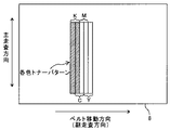
また、本プリンタは、電源投入時あるいは所定枚数のプリントを行う度に、色ずれ量補正処理も実施するようになっている。そして、この色ずれ量補正処理において、中間転写ベルト8の幅方向の一端部と他端部とにそれぞれ、図4に示すようなシェブロンパッチPVと呼ばれるY,M,C,Kの各色トナー像からなる色ずれ検知用画像を形成する。
The printer also performs color misregistration correction processing when the power is turned on or whenever a predetermined number of prints are performed. In this color misregistration amount correction processing, Y, M, C, and K color toner images called chevron patches PV as shown in FIG. 4 are respectively provided at one end and the other end of the
シェブロンパッチPVは、図4に示すように、Y,M,C,Kの各色のトナー像を主走査方向から約45[°]傾けた姿勢で、副走査方向であるベルト移動方向に所定ピッチで並べたラインパターン群である。このシェブロンパッチPVの付着量は、0.3[mg/cm2]程度である。 As shown in FIG. 4, the chevron patch PV has a predetermined pitch in the belt moving direction, which is the sub-scanning direction, with the toner images of each color of Y, M, C, and K inclined by about 45 [°] from the main scanning direction. Is a line pattern group arranged in. The amount of the chevron patch PV attached is about 0.3 [mg / cm 2 ].
そして、シェブロンパッチPV内の各色トナー像を検知することで、各色トナー像における主走査方向(感光体軸線方向)の位置、副走査方向(ベルト移動方向)の位置、主走査方向の倍率誤差、主走査方向からのスキューをそれぞれ検出する。ここで言う主走査方向とは、ポリゴンミラーでの反射に伴ってレーザー光が感光体表面上で位相する方向を示している。 Then, by detecting each color toner image in the chevron patch PV, the position in the main scanning direction (photoconductor axial direction), the position in the sub-scanning direction (belt moving direction), the magnification error in the main scanning direction in each color toner image, Each skew from the main scanning direction is detected. The main scanning direction here refers to the direction in which the laser light is phased on the surface of the photosensitive member as it is reflected by the polygon mirror.
このようなシェブロンパッチPV内のY,M,Cトナー像について、Kトナー像との検知時間差を光学センサ151で読み取っていく。同図では、紙面上下方向が主走査方向に相当し、左から順に、Y,M,C,Kトナー像が並んだ後、これらとは姿勢が90[°]異なっているK,C,M,Yトナー像が更に並んでいる。 For such Y, M, C toner images in the chevron patch PV, the optical sensor 151 reads the detection time difference from the K toner image. In the figure, the vertical direction of the paper surface corresponds to the main scanning direction, and after the Y, M, C, and K toner images are arranged in order from the left, the postures are different from those by 90 [°]. , Y toner images are further arranged.
基準色となるKとの検出時間差tyk、tmk、tckについての実測値と理論値との差に基づいて、各色トナー像の副走査方向のズレ量、即ちレジストズレ量を求める。そして、そのレジストズレ量に基づいて、光書込ユニット20のポリゴンミラー1面おき、即ち、1走査ラインピッチを1単位として、感光体1に対する光書込開始タイミングを補正して、各色トナー像のレジストズレを低減する。また、ベルト両端部間での副走査方向ズレ量の差に基づいて、各色トナー像の主走査方向からの傾き(スキュー)を求める。 そして、その結果に基づいて、光学系反射ミラーの面倒れ補正を実施して、各色トナー像のスキューズレを低減する。
Based on the difference between the actual measurement value and the theoretical value of the detection time differences tyk, tmk, and tck with respect to K as the reference color, the shift amount in the sub-scanning direction of each color toner image, that is, the registration shift amount is obtained. Then, on the basis of the registration deviation amount, the optical writing start timing on the
以上のように、シェブロンパッチPV内における各トナー像を検知したタイミングに基づいて光書込開始タイミングや面倒れを補正してレジストズレやスキューズレを低減する処理が、色ずれ補正処理である。このような色ずれ補正処理により、温度変化などで各色トナー像の中間転写ベルト8に対する形成位置が経時的にずれていくことに起因する画像の色ずれの発生を抑えることができる。
As described above, the color misregistration correction process is a process that corrects the optical writing start timing and surface tilt based on the detection timing of each toner image in the chevron patch PV to reduce registration deviation and skew deviation. By such a color misregistration correction process, it is possible to suppress the occurrence of color misregistration of an image due to a shift in the formation position of each color toner image with respect to the
また、低画像面積の画像形成動作が続くと、現像装置内に長時間とどまりつづける古いトナーが増えてくるため、トナー帯電特性が劣化し画像形成に用いると画像品質が悪くなる(現像能力低下、転写性低下)。このような古いトナーが現像装置内に滞留しないように一定のタイミングで感光体1の非画像領域に吐き出させ、吐き出し後にトナー濃度が低下した現像装置に新しいトナーを補給して現像装置内をリフレッシュするリフレッシュモードを備えている。
Further, if the image forming operation with a low image area continues, the amount of old toner that stays in the developing device for a long time increases, so that the toner charging characteristics deteriorate and the image quality deteriorates when used for image formation (development capability decreases, Transferability decline). In order to prevent such old toner from staying in the developing device, the toner is discharged to a non-image area of the
不図示の制御部は、各現像装置5Y,M,C,Kのトナー消費量と、各現像装置5Y,M,C,Kの動作時間とを記憶しておき、所定のタイミングで、現像装置5の所定期間の動作時間に対して、トナー消費量が閾値以下である否かを各現像装置5について調べる。そして、閾値以下の現像装置5について、リフレッシュモードを実行する。
A control unit (not shown) stores the toner consumption amount of each developing
リフレッシュモードが実行されると、感光体1の紙間に対応する非画像形成領域にトナー消費パターンが作成され、中間転写ベルト8に転写される(図5、図6、図7、図8)。
When the refresh mode is executed, a toner consumption pattern is created in the non-image forming area corresponding to the space between the sheets of the
トナー消費パターンの付着量は、現像装置の所定期間の動作時間に対するトナー消費量に基づき決定され、中間転写ベルト8上では単位面積当りの最大付着量が、1.2[mg/cm2]程度になることがある。また、図5に示す中間転写ベルト8に転写されたトナー消費パターン(a)のトナーQ/d分布を測定すると、ほぼ正規帯電極性に揃っている。本実施形態では、このトナー消費パターン(a)の大きさは、主走査方向:330[mm]としている。
The adhesion amount of the toner consumption pattern is determined based on the toner consumption amount with respect to the operation time of the developing device for a predetermined period, and the maximum adhesion amount per unit area on the
なお、図6では、各色のトナーパターンを下記で示すような大きさや位置関係の条件で、ベルト移動方向でY→M→C→Kの順に4色を重ねて中間転写ベルト8上に形成した場合を示している。
In FIG. 6, the toner patterns of the respective colors are formed on the
・各色の最大の副走査方向長さ:15[mm]
・各色の最大の主走査方向長さ:330[mm]
-Maximum sub-scanning direction length of each color: 15 [mm]
-Maximum length of each color in the main scanning direction: 330 [mm]
図7では、各色のトナーパターンを下記で示すような大きさや位置関係の条件で作成した場合を示している。 FIG. 7 shows a case where the toner patterns of the respective colors are created under conditions of size and positional relationship as shown below.
・各色の最大の副走査方向長さ:10[mm]
・各色の最大の主走査方向長さ:330[mm]
・ベルト移動方向におけるY色のトナーパターンの先端位置とM色のトナーパターンの先端位置との距離:5[mm]
・ベルト移動方向におけるM色のトナーパターンの先端位置とC色のトナーパターンの先端位置との距離:5[mm]
・ベルト移動方向におけるC色のトナーパターンの先端位置とK色のトナーパターンの先端位置との距離:5[mm]
-Maximum sub-scanning direction length of each color: 10 [mm]
-Maximum length of each color in the main scanning direction: 330 [mm]
The distance between the tip position of the Y toner pattern and the tip position of the M toner pattern in the belt moving direction: 5 [mm]
The distance between the tip position of the M toner pattern and the tip position of the C toner pattern in the belt moving direction: 5 [mm]
The distance between the tip position of the C toner pattern and the tip position of the K toner pattern in the belt moving direction: 5 [mm]
図8では、各色のトナーパターンを下記で示すような大きさや位置関係の条件で作成した場合を示している。 FIG. 8 shows a case where the toner patterns of the respective colors are created under conditions of size and positional relationship as shown below.
・各色の最大の副走査方向長さ:20[mm]
・各色の最大の主走査方向長さ:330[mm]
・ベルト移動方向におけるY色のトナーパターンの先端位置とM色のトナーパターンの先端位置との距離:5[mm]
・ベルト移動方向におけるM色のトナーパターンの先端位置とC色のトナーパターンの先端位置との距離:5[mm]
・ベルト移動方向におけるC色のトナーパターンの先端位置とK色のトナーパターンの先端位置との距離:5[mm]
-Maximum length of each color in the sub-scanning direction: 20 [mm]
-Maximum length of each color in the main scanning direction: 330 [mm]
The distance between the tip position of the Y toner pattern and the tip position of the M toner pattern in the belt moving direction: 5 [mm]
The distance between the tip position of the M toner pattern and the tip position of the C toner pattern in the belt moving direction: 5 [mm]
The distance between the tip position of the C toner pattern and the tip position of the K toner pattern in the belt moving direction: 5 [mm]
トナーパターンの副走査方向の長さは、通常の画像形成動作での作像履歴から決定する。そのため、Y,M,C,K色のトナーパターンの副走査方向の長さが、常に15[mm]など一定の長さがあるのではなく、各色で独立にトナーパターンの副走査方向の長さを例えば0〜15[mm]で可変としている。 The length of the toner pattern in the sub-scanning direction is determined from the image forming history in the normal image forming operation. Therefore, the length of the Y, M, C, and K toner patterns in the sub-scanning direction is not always a fixed length such as 15 [mm], but the length of the toner pattern in the sub-scanning direction independently for each color. The height is variable, for example, from 0 to 15 [mm].
中間転写ベルト8に形成された各色階調パターン、シェブロンパッチ、トナー消費パターンなどの未転写トナー像は、ベルトクリーニング装置100によって回収される。このとき、ベルトクリーニング装置100は、大量のトナーを中間転写ベルト8から除去しなければならない。
Non-transferred toner images such as color gradation patterns, chevron patches, and toner consumption patterns formed on the
しかしながら、従来の極性制御手段とブラシローラとからなるクリーニング装置や、正極性及び負極性それぞれのトナーを除去する2つのブラシローラとを備えたクリーニング装置では、未転写トナー像を一度で除去することができなかった。このような場合には、クリーニングしきれなかった中間転写ベルト8上のトナーが、次のプリント動作時に記録紙上に転写され、異常画像となる場合があった。
However, in a conventional cleaning device including a polarity control unit and a brush roller, or a cleaning device including two brush rollers for removing positive and negative toners, an untransferred toner image is removed at a time. I could not. In such a case, the toner on the
そこで、本実施形態に係るプリンタのベルトクリーニング装置100においては、各色階調パターン、シェブロンパッチ、トナー消費パターンなどの未転写トナー像を一度で除去することができるよう構成している。以下に、具体的に説明する。
Therefore, the
図9は、本実施形態に係るプリンタのベルトクリーニング装置100とその周囲とを拡大して示す拡大構成図である。図9において、ベルトクリーニング装置100は、中間転写ベルト8上の未転写トナー像を大まかに除去するためのプレクリーニング部100aを備えている。また、中間転写ベルト8上の正規帯電極性(負極性)とは逆極性(正極性)に帯電したトナーを除去する逆帯電トナークリーニング部100bを備えている。また、中間転写ベルト8上の正規帯電極性に帯電したトナーを除去する正規帯電トナークリーニング部100cとを備えている。
FIG. 9 is an enlarged configuration diagram showing the
プレクリーニング部100aには、プレクリーニング部材たるプレクリーニングブラシローラ101を有している。また、プレクリーニングブラシローラ101に付着したトナーを回収するプレ回収部材としてのプレ回収ローラ102、プレ回収ローラ102に当接してローラ表面からトナーを掻き取るプレ掻き取り部材としてのプレ掻き取りブレード103を有している。
The
未転写トナー像を構成するトナーのほとんどは、正規帯電極性(負極性)に帯電しているので、正規帯電極性とは逆極性(正極性)の電圧をプレクリーニングブラシローラ101に印加して、中間転写ベルト8上の負極性トナーを静電的除去するよう構成されている。また、プレ回収ローラ102には、プレクリーニングブラシローラ101よりも大きな正極性の電圧が印加されている。
Since most of the toner constituting the untransferred toner image is charged with a normal charging polarity (negative polarity), a voltage having a polarity (positive polarity) opposite to the normal charging polarity is applied to the
ベルトクリーニング装置100においては、未転写トナー像の90[%]が、プレクリーニングブラシローラ101により除去されるよう、プレクリーニングブラシローラ101に印加する電圧などが設定されている。
In the
また、プレクリーニング部100aには、画像形成装置本体に備えられた廃トナータンク(図示省略)に搬送するための搬送手段としての搬送スクリュ110が備えられている。
In addition, the
逆帯電トナークリーニング部100bは、プレクリーニング部100aよりも中間転写ベルト8移動方向下流側に配置されている。そして、トナーの正規帯電極性(負極性)とは逆極性(正極性)に帯電したトナーを静電的に除去する逆帯電トナークリーニング部材たる逆帯電トナークリーニングブラシローラ104を備えている。
The reversely charged
また、逆帯電トナークリーニングブラシローラ104に付着した逆帯電トナーを回収する逆帯電トナー回収部材としての逆帯電トナー回収ローラ105を備えている。さらに、逆帯電トナー回収ローラ105に当接してローラ表面から逆帯電トナーを掻き取る逆帯電トナー掻き取り部材としての逆帯電トナー掻き取りブレード106を備えている。
Further, a reversely charged
逆帯電トナークリーニングブラシローラ104には、負極性の電圧が印加されており、逆帯電トナー回収ローラ105には、逆帯電トナークリーニングブラシローラ104よりも大きな負極性の電圧が印加されている。また、この逆帯電トナークリーニング部100bは、中間転写ベルト8上のトナーに負極性の電荷を付与して、中間転写ベルト8上のトナーの帯電極性を、正規帯電極性(負極性)に揃える極性制御手段としての機能も有している。
A negative voltage is applied to the reversely charged toner cleaning
正規帯電トナークリーニング部100cは、逆帯電トナークリーニング部100bよりも中間転写ベルト8移動方向下流側に配置されている。そして、正規帯電極性に帯電したトナーを静電的に除去する正規帯電トナークリーニング部材たる正規帯電トナークリーニングブラシローラ107を備えている。
The normally charged
また、正規帯電トナークリーニングブラシローラ107に付着した正規帯電トナーを回収する正規帯電トナー回収部材としての正規帯電トナー回収ローラ108を備えている。さらに、正規帯電トナー回収ローラ108に当接してローラ表面から正規帯電トナーを掻き取る正規帯電トナー掻き取り部材としての正規帯電トナー掻き取りブレード109を備えている。
Further, a regular charged
正規帯電トナークリーニングブラシローラ107には、正極性の電圧が印加されており、正規帯電トナー回収ローラ108には、正規帯電トナークリーニングブラシローラ107よりも大きな負極性の電圧が印加されている。
A positive voltage is applied to the normally charged toner cleaning
プレクリーニング部100aと逆帯電トナークリーニング部100bとは、第一絶縁性シール部材112により仕切られており、第一絶縁性シール部材112は、プレクリーニングブラシローラ101と当接している。これにより、プレクリーニングブラシローラ101と逆帯電トナークリーニングブラシローラ104との間で放電が発生したり、逆帯電トナークリーニング部100bで除去したトナーがプレクリーニングブラシに再付着したりするのを抑制することができる。
The
また、逆帯電トナークリーニング部100bと正規帯電トナークリーニング部100cとは、第二絶縁性シール部材により仕切られており、第二絶縁性シール部材113は、逆帯電トナークリーニングブラシローラ104と当接している。これにより、逆帯電トナークリーニングブラシローラ104と正規帯電トナークリーニングブラシローラ107との間で放電が発生するのを抑制できる。また、正規帯電トナークリーニング部100cで除去したトナーが、逆帯電トナークリーニングブラシローラ104に再付着したりするのも抑制できる。
The reversely charged
また、ベルトクリーニング装置100の出口部には、正規帯電トナークリーニングブラシローラ107と当接する第三絶縁性シール部材114が設けられている。これにより、正規帯電トナークリーニングブラシローラ107とテンションローラ16との間で放電が発生するのを抑制することができる。
Further, a third
また、ベルトクリーニング装置100には、入口シール111、不図示の廃トナーケースが備えられている。廃トナーケースは、各クリーニング部100a,100b,100cで除去され搬送スクリュ110によって搬送されたトナーを貯留するものである。また、廃トナーケースは、ベルトクリーニング装置100に対して着脱可能に取り付けられており、メンテナンスなどのときに、廃トナーケースをベルトクリーニング装置100から取り外して廃トナーケースに溜まったトナーを除去できるようになっている。
Further, the
また、搬送スクリュ110とは別に、逆帯電トナークリーニング部100bや正規帯電トナークリーニング部100cで除去したトナーを、廃トナータンク(図示省略)に搬送する搬送スクリュを設けてもよい。
In addition to the
各クリーニングブラシローラ101,104,107は、回転自在に支持される金属製の回転軸部材と、これの周面に立設せしめられた複数の起毛からなるブラシ部とを具備しており、外径がφ15〜16[mm]である。
Each of the cleaning
起毛は、内部が導電性カーボンなどの導電性材料からなり、表面部がポリエステルなどの絶縁性材料からなる二層構造の芯鞘構造となっている。これにより、芯は、クリーニングブラシローラに印加された電圧とほぼ同じ電位になり、トナーを起毛表面に静電的に引き付けることができる。その結果、中間転写ベルト8上のトナーは、クリーニングブラシローラに印加された電圧の作用によって起毛に静電的に付着する。
The raised nail has a two-layer core-sheath structure in which the inside is made of a conductive material such as conductive carbon and the surface portion is made of an insulating material such as polyester. As a result, the lead has substantially the same potential as the voltage applied to the cleaning brush roller, and the toner can be electrostatically attracted to the raised surface. As a result, the toner on the
また、各クリーニングブラシローラ101,104,107の起毛を、二層構造の芯鞘構造ではなく、導電性繊維のみで構成してもよい。また、回転軸部材の法線方向に対して傾斜した姿勢で植毛されたいわゆる斜毛にしてもよい。
Further, the raised brushes of the cleaning
また、プレクリーニングブラシローラ101、正規帯電トナークリーニングブラシローラ107の起毛を芯鞘構造とし、逆帯電トナークリーニングブラシローラ104の起毛を導電性繊維のみで構成してもよい。逆帯電トナークリーニングブラシローラ104の起毛を導電性繊維のみで構成することで、逆帯電トナークリーニングブラシローラ104からトナーへの電荷注入が発生しやすくなる。よって、逆帯電トナークリーニングブラシローラ104によって、中間転写ベルト8上のトナーを良好に負極性に揃えることができる。
Further, the raising of the
一方、プレクリーニングブラシローラ101、正規帯電トナークリーニングブラシローラ107の起毛を芯鞘構造とすることによって、トナーへの電荷注入を抑制することができ、中間転写ベルト8上のトナーが正極性に帯電するのを抑制する。これにより、プレクリーニングブラシローラ101、正規帯電トナークリーニングブラシローラ107で、静電的に除去できないトナーが生じるのを抑制できる。
On the other hand, the brushing of the
また、各クリーニングブラシローラ101,104,107は、中間転写ベルト8に対し1[mm]食い込ませており、図示しない駆動手段によって、当接位置で起毛が、中間転写ベルト8移動方向とは逆方向(カウンター方向)に移動するよう回転する。当接位置において、起毛をカウンター方向に移動するよう回転させることで、クリーニングブラシローラと中間転写ベルト8との線速差を大きくすることができる。
Further, each cleaning
これにより、中間転写ベルト8のある箇所が、クリーニングブラシローラとの当接範囲を抜けるまでの間における起毛との接触確率が増え、良好に中間転写ベルト8からトナーを除去することができる。
This increases the probability of contact with the raised hair until a portion of the
ベルトクリーニング装置100においては、各回収ローラ102,105,108として、ステンレス鋼(SUS)ローラを用いた。なお、各回収ローラ102,105,108は、クリーニングブラシローラに付着したトナーを起毛と回収ローラとの電位勾配によってブラシから回収ローラに転位させる機能さえ発揮できれば、どのような材料からなっていてもかまわない。
In the
例えば、各回収ローラ102,105,108を導電性芯金に数[μm]〜100[μm]の高抵抗弾性チューブを被せたり、あるいはさらに絶縁コーティングしたりして、ローラ抵抗をlogR=12〜14[Ω・cm]にしたものを用いてもよい。
For example, each of the collecting
各回収ローラ102,105,108として、ステンレス鋼(SUS)ローラを用いることにより、コストダウンや印加電圧を低く抑えることができ、省電力化を図ることができるというメリットがある。一方、ローラ抵抗をlogR=12〜14[Ω・cm]にすることによって、回収ローラへの回収時におけるトナーへの電荷注入を抑制し、トナーが回収ローラの印加電圧の極性と同極性になり、トナー回収率が低下するのを抑制することができる。
By using a stainless steel (SUS) roller as each of the collecting
各クリーニングブラシローラ101,104,107の条件は、次の通りである。
・ブラシ材質:導電性ポリエステル(繊維内部に導電性カーボンを内包し、繊維表面はポリエステル、いわゆる芯鞘構造)
・ブラシ抵抗:10E6〜10E8[Ω]
・ブラシ植毛密度:6万〜15万[本/inch2]
・ブラシ繊維径:約25〜35[μm]
・ブラシ先端の毛倒れ処理:なし
・ブラシ径φ:14〜20[mm]
・中間転写ベルト8へのブラシ繊維喰い込み量:1〜1.5[mm]
The conditions of the cleaning
・ Brush material: Conductive polyester (Contains conductive carbon inside the fiber, the fiber surface is polyester, so-called core-sheath structure)
・ Brush resistance: 10E6 to 10E8 [Ω]
・ Brush flocking density: 60,000 to 150,000 [lines / inch 2 ]
・ Brush fiber diameter: about 25 to 35 [μm]
-Brush tipping treatment: None-Brush diameter φ: 14-20 [mm]
-Brush fiber biting amount into the intermediate transfer belt 8: 1 to 1.5 [mm]
プレクリーニングブラシローラ101への印加電圧は、中間転写ベルトに大量のトナーが付着している未転写トナー像が入力されたとき、良好なクリーニング性能が得られるように設定されている。また、逆帯電トナークリーニングブラシローラ104は、中間転写ベルト8上のトナーへ電荷が注入されるよう絶対値が高めに設定されている。また、ブラシ植毛密度、ブラシ抵抗、繊維径、印加電圧、繊維種類、ブラシ繊維喰込量はシステムによって最適化できるため、これに限らない。また、使用できる繊維の種類としては、ナイロン、アクリル、ポリエステルなどがある。
The applied voltage to the
各回収ローラ102,105,108の条件は、次のとおりである。
・回収ローラ芯金材質:ステンレス鋼(SUS303)
・回収ローラへのブラシ繊維喰い込み量:1〜1.5[mm]
回収ローラ材質、ブラシ繊維喰込量、印加電圧はシステムによって最適化できるため、これに限らない。
The conditions of each
・ Recovery roller core material: Stainless steel (SUS303)
-Brush fiber biting amount into the collection roller: 1 to 1.5 [mm]
The collection roller material, brush fiber entrapment amount, and applied voltage can be optimized by the system, and are not limited thereto.
各掻き取りブレード103,106,109の条件は次の通りである。
・回収ローラ芯金材質:ステンレス鋼(SUS304)
・ブレード当接角度:20[°]
・ブレード厚み:0.1[mm]
・回収ローラへのブレード喰い込み量:0.5〜1.5[mm]
The conditions of each
・ Recovery roller core material: Stainless steel (SUS304)
・ Blade contact angle: 20 [°]
・ Blade thickness: 0.1 [mm]
・ Amount of blade biting into the collection roller: 0.5 to 1.5 [mm]
ブレード当接角度、ブレード厚み、回収ローラへの喰い込み量は、システムによって最適化できるため、これに限らない。 The blade contact angle, the blade thickness, and the amount of biting into the collection roller can be optimized by the system, and are not limited thereto.
次にベルトクリーニング装置100のクリーニング動作について説明する。図9に示すように、二次転写部を通過した転写残トナーおよび未転写トナー像は入口シール111の当接部を越え、プレクリーニングブラシローラ101の位置に中間転写ベルト8の回転により移送される。
Next, the cleaning operation of the
プレクリーニングブラシローラ101には、トナーの正規帯電極性とは逆極性(正極性)の電圧が印加されている。そして、中間転写ベルト8とプレクリーニングブラシローラとの電位差で形成される電界により、中間転写ベルト8上の負極性に帯電したトナーを静電的に吸着して、プレクリーニングブラシローラ101へ移動させる。
A voltage having a polarity (positive polarity) opposite to the normal charging polarity of the toner is applied to the
プレクリーニングブラシローラ101に移動した負極性のトナーは、プレクリーニングブラシローラ101よりも値が絶対値で大きな正極性の電圧が印加されたプレ回収ローラ102との当接位置まで移送される。
The negative polarity toner that has moved to the
そして、プレクリーニングブラシローラ101とプレ回収ローラ102との電位差で形成される電界により、プレクリーニングブラシローラ101上に移動したトナーを静電的に吸着してプレ回収ローラ102上へ移動させる。プレ回収ローラ102に移動した負極性のトナーは、プレ掻き取りブレード103により回収ローラ表面から掻き落とされる。プレ掻き取りブレード103により掻き落とされたトナーは、搬送スクリュ110で装置外に排出される。
The toner that has moved onto the
プレクリーニングブラシローラ101により除去できたかった中間転写ベルト8上の未転写トナー像の負極性トナーや正極性トナー、正極性の転写残トナーは、逆帯電トナークリーニングブラシローラ104の位置に移送される。逆帯電トナークリーニングブラシローラ104には、トナーの正規帯電極性と同極性(負極性)の電圧が印加されており、電荷注入や放電により、中間転写ベルト8上のトナーの極性を負極性に揃える。
The negative toner, positive toner, and positive transfer residual toner of the untransferred toner image on the
また、これと同時に、中間転写ベルト8と逆帯電トナークリーニングブラシローラ104との電位差で形成される電界により、中間転写ベルト8上の正極性に帯電したトナーを静電的に吸着して逆帯電トナークリーニングブラシローラ104へ移動させる。逆帯電トナークリーニングブラシローラ104に移動した正極性のトナーは、逆帯電トナークリーニングブラシローラ104よりも値が絶対値で大きな負極性の電圧が印加された逆帯電トナー回収ローラ105との当接位置まで移送される。
At the same time, the positively charged toner on the
そして、逆帯電トナークリーニングブラシローラ104と逆帯電トナー回収ローラ105との電位差で形成される電界により、逆帯電トナークリーニングブラシローラ104上に移動したトナーを静電的に吸着して逆帯電トナー回収ローラ105上へ移動させる。逆帯電トナー回収ローラ105に移動した正極性のトナーは、逆帯電トナークリーニング掻き取りブレード106により回収ローラ表面から掻き落とされる。
Then, by the electric field formed by the potential difference between the reversely charged toner cleaning
次に、逆帯電トナークリーニングブラシローラ104により負極性にシフトしたトナーや、プレクリーニングブラシローラ101により除去できたかった負極性のトナーが、正規帯電トナークリーニングブラシローラ107に移送される。正規帯電トナークリーニングブラシローラ107へ移送されるトナーは、逆帯電トナークリーニングブラシローラ104により負極性に極性制御されている。
Next, the toner shifted to the negative polarity by the reversely charged toner cleaning
また、プレクリーニングブラシローラ101や逆帯電トナークリーニングブラシローラ104によって中間転写ベルト8上のトナーは、ほとんど除去されている。このため、この正規帯電トナークリーニングブラシローラ107へ移送されるトナーは、ごく少量である。
Further, the toner on the
この正規帯電トナークリーニングブラシローラ107へ移送された負極性に揃えられた、ごく少量の中間転写ベルト8上のトナーは、正規帯電トナークリーニングブラシローラ107に静電的に付着する。そして、その後、正規帯電トナー回収ローラ108により回収され、正規帯電トナー掻き取りブレード109により、正規帯電トナー回収ローラ108から掻き落とされる。
A very small amount of toner on the
このように、ベルトクリーニング装置100によれば、プレクリーニングブラシローラ101を設けることによって、プレクリーニングブラシローラ101で未転写トナー像の大部分をしめる負極性のトナーが大まかに除去される。これにより、逆帯電トナークリーニングブラシローラ104や正規帯電トナークリーニングブラシローラ107に入力されるトナー量を減らすことができる。
As described above, according to the
正規帯電トナークリーニングブラシローラ107へ移送される中間転写ベルト8上のトナーは、プレクリーニングブラシローラ101、逆帯電トナークリーニングブラシローラ104で除去されなかったものであり、トナー量としては、ごく少量である。また、逆帯電トナークリーニングブラシローラ104により負極性に揃えられたトナーである。よって、正規帯電トナークリーニングブラシローラ107で、残りのトナーを良好に除去することができる。
The toner on the
これにより、中間転写ベルト8に大量のトナーが付着している未転写トナー像でも、良好に中間転写ベルト8から除去することができる。また、未転写トナー像よりもトナー量が少ない転写残トナーは、これら3つのクリーニングブラシローラ101,104,107によって良好に除去することができる。
As a result, even an untransferred toner image in which a large amount of toner is attached to the
また、ベルトクリーニング装置100は、逆帯電トナークリーニングブラシローラ104で中間転写ベルト8上の正極性のトナーを除去しているが、これに限るものではない。すなわち、逆帯電トナークリーニング部100bを極性制御部に変更して、中間転写ベルト8上の正極性のトナーを除去しない構成としてもよい。
The
この場合、プレクリーニングブラシローラ101を通過した中間転写ベルト8上のトナーは、極性制御部により、負極性に揃えられて、極性制御部よりもベルト移動方向下流の正規帯電トナークリーニングブラシローラ107へ移送される。そして、正規帯電トナークリーニングブラシローラ107で、負極性のトナーを除去する。極性制御部で、中間転写ベルト8上のトナーに負極性の電荷を注入する手段としては、導電性ブラシ、導電性ブレード、コロナチャージャなどでよい。
In this case, the toner on the
また、トナーの帯電極性を負極性に揃えるのではなく、正極性に揃えるようにして、極性制御部よりもベルト移動方向下流に、負極性の電圧が印加されたクリーニングブラシローラを配置して、中間転写ベルト上の正極性に揃えられたトナーを除去する構成でもよい。このような、構成でも、プレクリーニングブラシローラ101で、中間転写ベルト8から未転写トナー像のトナーを大まかに除去するので、極性制御部へ移送されるトナー量は少なくなっている。
Also, instead of aligning the charging polarity of the toner to negative polarity, arrange a cleaning brush roller to which a negative voltage is applied downstream of the polarity control unit in the belt moving direction so that it is aligned to positive polarity. A configuration in which toner having a positive polarity on the intermediate transfer belt is removed may be employed. Even in such a configuration, since the toner of the untransferred toner image is roughly removed from the
よって、極性制御部で、中間転写ベルト8上のトナーを良好に、一方の極性に揃えることができる。その結果、極性制御部の下流に配置されたクリーニングブラシローラで中間転写ベルト8上のトナーを良好に静電的に除去できる。よって、大量のトナーが付着した未転写トナー像がベルトクリーニング装置100に入力されても、良好にクリーニングすることができる。
Therefore, the polarity control unit can satisfactorily align the toner on the
また、ベルトクリーニング装置100では、各回収ローラ102,105,108、各クリーニングブラシローラ101,104,107に電圧を印加しているが、回収ローラにのみ電圧を印加する構成でもよい。この場合は、クリーニングブラシローラの繊維抵抗による電位降下によって、回収ローラとの接触部を介する形態で、回収ローラに印加されたバイアス電圧よりも幾分低いバイアス電圧がクリーニングブラシローラに印加されている状態となる。
In the
これにより、回収ローラとクリーニングブラシローラとの間に電位差が形成され、回収ローラ方向へ電位勾配によりクリーニングブラシローラから回収ローラへトナーを静電的に移動させることができる。 Thereby, a potential difference is formed between the collection roller and the cleaning brush roller, and the toner can be electrostatically moved from the cleaning brush roller to the collection roller by a potential gradient in the direction of the collection roller.
ベルトクリーニング装置100は、トナー付着量として0.05[mg/cm2]程度以下の少量の転写残トナーから、最大1.0[mg/cm2]になる未転写トナーまで広範囲のトナー付着量に対応しなければならない。
The
クリーニングが最良となるクリーニング電流すなわち目標電流値は、前記当接箇所に入力されるトナーの付着量によって変化する。すなわち、トナー付着量が多いときは大きい電流値(電圧値)となり、トナー付着量が少ないときはトナー付着量が多いときよりも小さい電流値(電圧値)となる。 The cleaning current that provides the best cleaning, that is, the target current value, varies depending on the amount of toner that is input to the contact portion. That is, when the toner adhesion amount is large, the current value (voltage value) is large, and when the toner adhesion amount is small, the current value (voltage value) is smaller than when the toner adhesion amount is large.
なお、前記クリーニング電流は、クリーニングブラシローラ101,104,107それぞれと中間転写ベルト8との当接箇所を流れる目標電流である。表1に、未転写トナー用電圧と転写残トナー用電圧との目標電流値の一例を示す。
The cleaning current is a target current that flows through the contact points between the cleaning

本実施形態でのプロセス線速は、350[mm/s]とする。もちろん、100〜800[mm/s]のプロセス線速に対応可能である。目標電流は線速に比例させた値とすればよい。例えば、プロセス線速が350[mm/s]の半分である175[mm/s]の場合は、目標電流値をプロセス線速350[mm/s]の半分にすればよい。また、プロセス線速が350[mm/s]の2倍である700[mm/s]の場合は、目標電流値をプロセス線速350[mm/s]の2倍にすればよい。 The process linear velocity in this embodiment is set to 350 [mm / s]. Of course, it is possible to cope with a process linear velocity of 100 to 800 [mm / s]. The target current may be a value proportional to the linear velocity. For example, when the process linear velocity is 175 [mm / s] which is half of 350 [mm / s], the target current value may be half of the process linear velocity 350 [mm / s]. In addition, when the process linear velocity is 700 [mm / s], which is twice the 350 [mm / s], the target current value may be set twice the process linear velocity 350 [mm / s].
図10は、プレクリーニングブラシローラ101やプレ回収ローラ102への電圧印加のタイミングチャートである。プレクリーニングブラシローラ101やプレ回収ローラ102への電圧印加は、図10に示すように、転写残トナーと未転写トナーそれぞれのクリーニングが最良となる目標電流を流すために、電圧の切り替えを行う。つまり、画像部では、転写残トナーのクリーニング性が最良となるように、プレクリーニングブラシローラ101とプレ回収ローラ102とに低い電圧を印加する。
FIG. 10 is a timing chart of voltage application to the
一方、リフレッシュモードが実行され紙間でトナーパターンが作成された場合は、未転写トナーのクリーニング性が最良となるように、プレクリーニングブラシローラ101とプレ回収ローラ102とに印加する電圧を高い電圧に切り替える。このような電圧の切り替えは、トナーパターンが静電クリーニング部、詳細には、プレクリーニング部100aに到達する直前に行われる。
On the other hand, when the refresh mode is executed and a toner pattern is created between sheets, the voltage applied to the
また、本実施形態では、プレクリーニングブラシローラ101及びプレ回収ローラ102の印加電圧を切り替えている。なお、紙間部でトナー消費パターンが形成されない場合は、電圧の切り替えを行わない。
In the present embodiment, the applied voltages of the
図10のタイミングチャートを用いて、本実施形態におけるプレクリーニングブラシローラ101及びプレ回収ローラ102への印加電圧制御を説明する。
Control of applied voltage to the
不図示の制御部が、各現像装置5Y,M,C,Kのトナー消費量と、各現像装置5Y,M,C,Kの動作時間とを記憶しておく。そして、所定のタイミングで、各現像装置5Y,M,C,Kの所定期間の動作時間に対して、トナー消費量が閾値以下である否かを各現像装置5Y,M,C,Kについて調べ、閾値以下の現像装置5Y,M,C,Kについて、リフレッシュモードを実行する。
A control unit (not shown) stores the toner consumption amount of each of the developing
リフレッシュモードが実行されると、感光体1の紙間に対応する非画像形成領域にトナー消費パターンが作成され、そのトナー消費パターンが感光体1から中間転写ベルト8に転写される。トナー消費パターンの付着量は、現像装置5Y,M,C,Kの所定期間の動作時間に対するトナー消費量に基づき決定される。
When the refresh mode is executed, a toner consumption pattern is created in a non-image forming area corresponding to the space between the sheets of the
なお、本実施形態では、このトナー消費パターンの大きさを25[mm]×250[mm]としている。また、感光体回転方向で紙間開始位置から15[mm]だけ間隔を空けた位置からトナー消費パターンが作像される。 In this embodiment, the size of the toner consumption pattern is 25 [mm] × 250 [mm]. Further, a toner consumption pattern is formed from a position spaced by 15 [mm] from the sheet start position in the photoconductor rotation direction.
まず、図10で1回目の画像部では、転写残トナー用電圧として、プレクリーニングブラシローラ101に+2000[V]の電圧が印加され、プレ回収ローラ102には+2400[V]の電圧が印加される。
First, in the first image portion in FIG. 10, a voltage of +2000 [V] is applied to the
そして、図10で1回目の紙間が始まるとともに、未転写トナー用電圧として、プレクリーニングブラシローラ101に印加する電圧を+2400[V]にする。また、それに同期してプレ回収ローラ102に印加する電圧を+2800[V]にする。
Then, the first paper interval starts in FIG. 10, and the voltage applied to the
なお、リフレッシュモード時の電圧を印加してから、リフレッシュモードによるトナー消費パターンが、プレクリーニングブラシローラ101からプレ回収ローラ102に回収されるまでの所定時間だけ、上記電圧を印加すればよい。
The voltage may be applied only for a predetermined time after the voltage in the refresh mode is applied until the toner consumption pattern in the refresh mode is collected from the
そして、トナー消費パターンクリーニング開始から前記所定時間が経過した後、プレクリーニングブラシローラ101に印加する電圧を、+2000[V]にする。また、それに同期してプレ回収ローラ102に印加する電圧を+2400[V]にする。すなわち、2回目の画像部に対する転写残トナー用電圧に切り替える。
Then, after the predetermined time has elapsed since the start of toner consumption pattern cleaning, the voltage applied to the
その後、図10で、2回目の紙間でも上述した1回目の紙間と同様に、未転写トナー用電圧に切り替えが行われ、その後、3回目の画像部に対する転写残トナー用電圧に切り替えられる。 Thereafter, in FIG. 10, similarly to the first paper interval described above, the second transfer is switched to the untransferred toner voltage, and then switched to the third transfer residual voltage for the image portion. .
なお、図10で、3回目の紙間ではリフレッシュモードが実行されず、紙間にトナー消費パターンが形成されない。このため、プレクリーニングブラシローラ101及びプレ回収ローラ102への印加電圧は、転写残トナー用電圧と同じままである。
In FIG. 10, the refresh mode is not executed during the third sheet interval, and no toner consumption pattern is formed between the sheets. For this reason, the voltage applied to the
このようにすることで、大量のトナーがプレクリーニングブラシローラ101に入力されたとしても、プレクリーニングブラシローラ101からプレ回収ローラ102にトナーを移動できるため、プレクリーニングブラシローラ101にトナーが滞留することが無い。
In this way, even if a large amount of toner is input to the
本実施形態において、ベルトクリーニング装置100の印加電圧を設定変更する場合、まず、プリンタ内の温湿度センサの測定値に基づいて、上記表1に示した設定テーブルから前記測定値に対応した温湿度環境の目標電流値を読み出して使用する。
In this embodiment, when changing the setting of the applied voltage of the
本実施形態に係るプリンタでは、電源投入時あるいは所定枚数のプリントを行うたびに行われるプロセスコントロール時以外にも、ベルトクリーニング装置の印加電圧の設定変更処理を行う。詳しくは、温湿度センサの測定値が、前回の設定変更処理時に記録した温湿度の測定値と比較して所定値以上変化したときに、電圧設定値の設定変更処理を行う。 The printer according to the present embodiment performs setting change processing of the applied voltage of the belt cleaning device other than at the time of process control performed every time the power is turned on or a predetermined number of prints are performed. Specifically, when the measured value of the temperature / humidity sensor changes by a predetermined value or more as compared with the measured value of temperature / humidity recorded during the previous setting change process, the setting change process for the voltage setting value is performed.
例えば、温度変化が10[℃]以上または湿度変化が50[%]以上のときは、設定変更処理を実行して、現在の温湿度測定値に対応した設定テーブルの目標電流値となるように印加電圧の設定変更を行う。 For example, when the temperature change is 10 [° C.] or more or the humidity change is 50 [%] or more, the setting change process is executed so that the target current value of the setting table corresponding to the current temperature and humidity measurement value is obtained. Change the setting of the applied voltage.
なお、本実施形態では、温湿度環境を3つに大別して3種類の設定値を持つ例であるが、より細かく対応するために温湿度環境をもっと細かく区分して3種類以上の設定値を持つようにしても良い。 In this embodiment, the temperature / humidity environment is broadly divided into three and has three types of setting values. However, in order to respond more finely, the temperature / humidity environment is further divided into three or more types of setting values. You may have it.
ベルトクリーニング装置100の印加電圧の設定変更処理は、中間転写ベルト8及びベルトクリーニング装置100を駆動し、且つ、ベルトクリーニング装置100に対してトナー入力が無い状態で行う。
The setting change process of the applied voltage of the
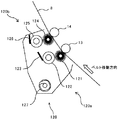
ここで、本実施形態においては、各クリーニングブラシローラ101,104,107や、各回収ローラ102,105,108の印加電圧の電圧設定値の変更を同時に行う。そのため、各クリーニングブラシローラ101,104,107、各回収ローラ102,105,108のそれぞれに接続された6つの電源130a,131a,132a,133a,134a,135aから所定の電圧を印加する。
Here, in the present embodiment, the voltage setting values of the applied voltages of the cleaning
そして、プレクリーニングブラシローラ101及びプレ回収ローラ102に電圧を印加する電源130a及び電源131aを流れる電流値IB1及び電流値IC1を検出する。 また、逆帯電トナークリーニングブラシローラ104及び逆帯電トナー回収ローラ105に電圧を印加する電源132a及び電源133aを流れる電流値IB2及び電流値IC2を検出する。さらに、正規帯電トナークリーニングブラシローラ107及び正規帯電トナー回収ローラ108に電圧を印加する電源134a及び電源135aを流れる電流値IB3及び電流値IB4を検出する。
Then, the current value IB1 and the current value IC1 flowing through the power supply 130a and the
電流値IB1と電流値IC1との合計値IT1(IB1+IC1)、電流値IB2と電流値IC2との合計値IT2(IB2+IC2)、及び、電流値IB3と電流値IC3との合計値IT3(IB3+IC3)が、それぞれ目標電流値となるような電圧を特定する。そして、各クリーニングブラシローラ101,104,107や、各回収ローラ102,105,108の印加電圧の電圧設定値を同時に変更する。 A total value IT1 (IB1 + IC1) of the current value IB1 and the current value IC1, a total value IT2 (IB2 + IC2) of the current value IB2 and the current value IC2, and a total value IT3 (IB3 + IC3) of the current value IB3 and the current value IC3 are obtained. Then, the voltages that respectively become the target current values are specified. And the voltage setting value of the applied voltage of each cleaning brush roller 101,104,107 and each collection | recovery roller 102,105,108 is changed simultaneously.
以後の作像動作では、次に電圧設定値の変更が行われるまでは、この設定値が用いられる。なお、本実施形態では、電源130a,132a,134aを特に区別しないときには、それぞれを流れる電流値IB1,IB2,IB3を単に電流値IBという。また、電源131a,133a,135aを特に区別しないときには、それぞれを流れる電流値IC1,IC2,IC3を単に電流値ICという。また、電流値IB1と電流値IC1との合計値IT1、電流値IB2と電流値IC2との合計値IT2、及び、電流値IB3と電流値IC3との合計値IT3を、特に区別しないときには単に合計値ITという。
In the subsequent image forming operation, this set value is used until the voltage set value is next changed. In the present embodiment, when the
図11に、電圧設定値変更処理の一例のフローチャートを示す。なお、図11においては、各クリーニング部100a,100b,100cに対して同時に同じ電圧設定値変更処理を実施するため、各クリーニング部100a,100b,100cの区別をすることなく表記している。
FIG. 11 shows a flowchart of an example of the voltage set value change process. In FIG. 11, the cleaning
電圧設定値の設定変更時に、各クリーニングブラシローラ101,104,107や、各回収ローラ102,105,108に対して、最初に印加する電圧は、前回電圧設定変更したときの電圧を初期値として記憶しておき、それを読み出して行う。表2に、前記初期値の一例を示す。
When the voltage setting value is changed, the initial voltage applied to each of the cleaning
これは、設定したい電圧からかけ離れた電圧を印加すると、中間転写ベルト8を伝わりクリーニングブラシローラ間を流れる電流が大きくなって、各クリーニングブラシローラ101,104,107や中間転写ベルト8の劣化が加速してしまうためである。
This is because when a voltage far from the voltage to be set is applied, the current flowing through the
電圧設定値変更処理では、まず図11に示すように、プリンタ内の温湿度センサの測定値に基づいて、上記表1に示した設定テーブルから前記測定値に対応した温湿度環境の目標電流値を読み出す(S1)。 In the voltage set value changing process, first, as shown in FIG. 11, based on the measured value of the temperature and humidity sensor in the printer, the target current value of the temperature and humidity environment corresponding to the measured value from the setting table shown in Table 1 above. Is read (S1).
次に、各クリーニングブラシローラ101,104,107、各回収ローラ102,105,108のそれぞれに接続された6つの電源130a,131a,132a,133a,134a,135aから所定の電圧を印加する(S2)。
Next, a predetermined voltage is applied from the six
なお、この際、各クリーニングブラシローラ101,104,107に印加する電圧VB1、電圧VB2、電圧VB3は、前述したように記憶させておいた前回電圧設定変更したときの電圧を初期値として読み出したものを用いる。また、各回収ローラ102,105,108に印加する電圧VC1,電圧VC2,電圧VC3としては、電圧VB1、電圧VB2、電圧VB3よりも400[V]高い電圧を用いる。
At this time, the voltages VB1, VB2, and VB3 applied to the cleaning
そして、各クリーニングブラシローラ101,104,107に電圧を印加する電源130a,132a,134aを流れる電流値IB1,IB2,IB3を検出する。同様に、各回収ローラ102,105,108に電圧を印加する電源131a,133a,135aを流れる電流値IC1,IC2,IC3を検出する。また、これら検出された電流値から、電流値IB1と電流値IC1との合計値IT1(IB1+IC1)、電流値IB2と電流値IC2との合計値IT2(IB2+IC2)、及び、電流値IB3と電流値IC3との合計値IT3(IB3+IC3)を求める(S3)。
Then, current values IB1, IB2, and IB3 flowing through the
そして、合計値IT1,IT2,IT3が、目標電流値の80[%]以上、目標電流値の120[%]以下の範囲内にあるか判断する(S4)。 Then, it is determined whether the total values IT1, IT2, IT3 are within the range of 80 [%] of the target current value and 120 [%] of the target current value (S4).
合計値IT1,IT2,IT3が、目標電流値の80[%]以上、目標電流値の120[%]以下の範囲内にあれば(S4でYES)、そのときの電圧VB1,VB2,VB3、電圧VC1,VC2,VC3を電圧設定値として決定する(S5)。これにより、一連の電圧設定変更処理を終了する(S6)。 If the total values IT1, IT2, IT3 are in the range of 80% or more of the target current value and 120% or less of the target current value (YES in S4), then the voltages VB1, VB2, VB3, The voltages VC1, VC2, and VC3 are determined as voltage setting values (S5). Thereby, a series of voltage setting change processing is complete | finished (S6).
一方、合計値IT1,IT2,IT3が、目標電流値の80[%]以上、目標電流値の120[%]以下の範囲内でなければ(S4でNO)、合計値IT1,IT2,IT3が、目標電流値の下限よりも小さいか判断する(S7)。 On the other hand, if the total values IT1, IT2, IT3 are not within the range of 80% or more of the target current value and 120% or less of the target current value (NO in S4), the total values IT1, IT2, IT3 are Then, it is determined whether it is smaller than the lower limit of the target current value (S7).
合計値IT1,IT2,IT3が、目標電流値の下限よりも小さい場合は(S7でYES)、電圧VB1,VB2,VB3よりも100[V]高い電圧を求め、これを電圧VB’1,VB’2,VB’3をする。また、この電圧VB’1,VB’2,VB’3よりも400[V]高い電圧を求め、これを電圧VC’1,VC’2,VC’3とする(S8)。 When the total values IT1, IT2, IT3 are smaller than the lower limit of the target current value (YES in S7), a voltage that is 100 [V] higher than the voltages VB1, VB2, VB3 is obtained, and this is obtained as the voltages VB′1, VB. Do '2, VB'3. Further, a voltage 400 [V] higher than the voltages VB'1, VB'2, and VB'3 is obtained, and these are set as voltages VC'1, VC'2, and VC'3 (S8).
逆に、合計値IT1,IT2,IT3が、目標電流値の下限よりも大きい場合は(S7でNO)、電圧VB1,VB2,VB3よりも100[V]低い電圧を求め、これを電圧VB’1,VB’2,VB’3をする。また、この電圧VB’1,VB’2,VB’3よりも400[V]高い電圧を求め、これを電圧VC’1,VC’2,VC’3とする(S9)。 Conversely, when the total values IT1, IT2, IT3 are larger than the lower limit of the target current value (NO in S7), a voltage that is 100 [V] lower than the voltages VB1, VB2, VB3 is obtained, and this is obtained as the voltage VB ′. 1, VB′2, VB′3. Further, a voltage that is 400 [V] higher than the voltages VB′1, VB′2, and VB′3 is obtained, and these are set as voltages VC′1, VC′2, and VC′3 (S9).
そして、各クリーニングブラシローラ101,104,107に電圧VB’1,VB’2,VB’3を印加し、各回収ローラ102,105,108に電圧VC’1,VC’2,VC’3を印加する(S10)。その後、電流値IB1,IB2,IB3及び電流値IC1,IC2,IC3を検出し、上述したような一連の制御を繰り返し行う。
Then, voltages VB′1, VB′2, and VB′3 are applied to the cleaning
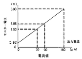
図12は、検知時の電流とモニター電圧との関係を示したグラフである。プリンタ60では、高圧電源の電流はモニター電圧としてモニター出力され、言い換えれば、高圧電圧を流れる電流を制御部がモニター電圧に変換し、このモニター電圧を制御部がAD変換してソフト処理する。
FIG. 12 is a graph showing the relationship between the current at the time of detection and the monitor voltage. In the
図12に示すように、モニター電圧は、電源を流れる電流の値が0[μA]でも、0.50[V]出力されることになる。しかしながら、図12に示す電流値とモニター電圧との関係は理論値として求めたものであり、実際には電源の個体差や電源に設けられた制御基板側の回路定数などの影響で、電源を流れる電流が小さいほど、電流値とモニター電圧との関係に誤差を持つ場合がある。 As shown in FIG. 12, the monitor voltage is output at 0.50 [V] even when the value of the current flowing through the power supply is 0 [μA]. However, the relationship between the current value and the monitor voltage shown in FIG. 12 is obtained as a theoretical value. Actually, the power source is affected by the individual difference of the power source or the circuit constant on the control board side provided in the power source. As the flowing current is smaller, there may be an error in the relationship between the current value and the monitor voltage.
このような誤差がある場合、例えば、実際には電源に流れる電流が0[μA]にもかかわらず、モニター電圧が0.50[V]よりも小さい値が出力され、電源を流れる電流がマイナスとして検知されてしまうことになる。そのため、本実施形態では、モニター電圧に基づいて検出された電流値IBまたは電流値ICが、予め設定された所定電流値よりも小さい場合を考慮した電圧値設定処理が実行可能となっている。 When there is such an error, for example, although the current flowing through the power supply is actually 0 [μA], a value smaller than 0.50 [V] is output and the current flowing through the power supply is negative. Will be detected. Therefore, in the present embodiment, it is possible to execute a voltage value setting process considering a case where the current value IB or the current value IC detected based on the monitor voltage is smaller than a predetermined current value set in advance.
図1は、モニター電圧に基づいて検出された電流値IBまたは電流値ICが、予め設定された所定電流値よりも小さい場合を考慮した電圧値設定処理のフローチャートである。 FIG. 1 is a flowchart of a voltage value setting process considering a case where the current value IB or the current value IC detected based on the monitor voltage is smaller than a predetermined current value set in advance.
本実施形態では、モニター電圧に基づいて検出された電流値IBまたは電流値ICが(図1のS1)、予め設定された第一所定電流値よりも小さいか判断する(図1のS2)。予め設定された第一所定電流値よりも小さい場合には(図1のS2でYES)、前記第一所定電流値よりも小さい電流値IBまたは電流値ICに変えて第二所定電流値を用いて前記合計値ITを求める(図1のS3)。 In the present embodiment, it is determined whether the current value IB or the current value IC detected based on the monitor voltage (S1 in FIG. 1) is smaller than a preset first predetermined current value (S2 in FIG. 1). If the current value is smaller than the preset first predetermined current value (YES in S2 of FIG. 1), the second predetermined current value is used instead of the current value IB or the current value IC smaller than the first predetermined current value. The total value IT is obtained (S3 in FIG. 1).
すなわち、(1)電流値IB<第一所定電流値の関係を満たす場合には、電流値ICと第二所定電流値とで前記合計値ITを求める。または、(2)電流値IC<第一所定電流値の関係を満たす場合には、電流値IBと第二所定電流値とで前記合計値ITを求める。 That is, (1) When the relationship of current value IB <first predetermined current value is satisfied, the total value IT is obtained from the current value IC and the second predetermined current value. Alternatively, (2) when the relationship of current value IC <first predetermined current value is satisfied, the total value IT is obtained from the current value IB and the second predetermined current value.
なお、第二所定電流値は第一所定電流値以上の大きさの電流値であり、本実施形態においては、第一所定電流値と第二所定電流値とを同じ電流値としており、以下、両者を区別することなく単に所定電流値ともいう。第一所定電流値と第二所定電流値とを同じ電流値とすることで、制御が複雑化するのを抑制することができる。 The second predetermined current value is a current value greater than or equal to the first predetermined current value. In the present embodiment, the first predetermined current value and the second predetermined current value are the same current value, and Both are also simply referred to as a predetermined current value without distinction. By making the first predetermined current value and the second predetermined current value the same current value, it is possible to suppress complication of control.
例えば、所定電流値を0[μA]とした場合、検出された電流値IBまたは電流値ICが0[μA]よりも小さい値、すなわちマイナスの電流値として検出されたら、そのマイナスの電流値に変えて所定電流値である0[μA]を用いて前記合計値ITを求める。 For example, when the predetermined current value is 0 [μA], if the detected current value IB or current value IC is detected as a value smaller than 0 [μA], that is, a negative current value, the negative current value is changed to the negative current value. The total value IT is obtained using 0 [μA] which is a predetermined current value.
一方で、モニター電圧に基づいて検出された電流値IBと電流値ICとが、共に所定電流値以上であれば、電流値IBと電流値ICとで前記合計値ITを求める(S5)。 On the other hand, if the current value IB and the current value IC detected based on the monitor voltage are both equal to or greater than the predetermined current value, the total value IT is obtained from the current value IB and the current value IC (S5).
そして、このようにして求められた前記合計値ITを用いて、図11を用いて説明したような方法により、目標電流値が得られるような電圧設定値の設定変更処理を実行する(図1のS4)。 Then, by using the total value IT obtained in this way, the voltage setting value setting changing process for obtaining the target current value is executed by the method described with reference to FIG. 11 (FIG. 1). S4).
なお、上述したように前記合計値ITとしては、目標電流値の80[%]以上、目標電流値の120[%]以下の範囲内にあれば、図13に示すように良好なクリーニング性が得られるクリーニング電流となる。すなわち、良好なクリーニング性を得ることが可能なクリーニングブラシローラや回収ローラに印加する電圧には、ある程度の幅がある。そのため、前記マイナスの電流値に変えて0[μA]を用いて前記合計値ITを求め、電圧設定値の設定変更を行ってもクリーニング性には問題ない。 As described above, if the total value IT is within the range of 80 [%] or more of the target current value and 120 [%] or less of the target current value, good cleaning properties can be obtained as shown in FIG. The resulting cleaning current is obtained. That is, the voltage applied to the cleaning brush roller and the collection roller that can obtain good cleaning properties has a certain range. Therefore, even if the total value IT is obtained by using 0 [μA] instead of the negative current value and the voltage setting value is changed, there is no problem in cleaning performance.
また、このことから、例えば、第一所定電流値を0[μA]とし第二所定電流値を1[μA]として電圧設定値の設定変更を行った場合でも、前記合計値ITを良好なクリーニング性が得られる所定範囲内の電流値から外れないようにすることができる。 For this reason, for example, even when the first predetermined current value is set to 0 [μA] and the second predetermined current value is set to 1 [μA], and the voltage setting value is changed, the total value IT can be satisfactorily cleaned. Thus, it is possible to prevent the current value from deviating from a current value within a predetermined range.
これにより、設定変更された後の電圧設定値で、クリーニングブラシローラ及び回収ローラに電圧を印加したときに、前記接触部分を実際に流れるクリーニング電流の値が、良好なクリーニング性が得られる所定範囲内から外れてしまうのを抑制できる。よって、適切なクリーニング電流を流すことができずに、良好なクリーニング性が得られなくなるのを抑制することができる。 Thus, when the voltage is applied to the cleaning brush roller and the collection roller with the voltage setting value after the setting change, the value of the cleaning current that actually flows through the contact portion is within a predetermined range in which good cleaning properties can be obtained. It can suppress that it comes off from the inside. Therefore, it is possible to prevent a proper cleaning current from flowing and a good cleaning performance from being obtained.
また、前記所定電流値としては、前記目標電流値を±10[%]の範囲内でオフセットしたオフセット量に対応する電流値としてもよい。例えば、前記目標電流値が20[μA]のときには、前記所定電流値を0[μA]〜2[μA]とする。これにより、電圧設定値を設定変更した後に前記接触部分を実際に流れるクリーニング電流が、良好なクリーニング性を得られる範囲内に収まるため、良好なクリーニング性をより確実に確保することできる。 The predetermined current value may be a current value corresponding to an offset amount obtained by offsetting the target current value within a range of ± 10 [%]. For example, when the target current value is 20 [μA], the predetermined current value is set to 0 [μA] to 2 [μA]. As a result, the cleaning current that actually flows through the contact portion after the voltage setting value is changed is within the range where good cleaning properties can be obtained, so that good cleaning properties can be ensured more reliably.
また、本実施形態では、制御部により、電流値IBから変換された第一モニター電圧と、電流値ICから変換された第二モニター電圧とを用いて、各電源を流れる電流値を検知し、それら検知した電流値の合計から前記合計値ITを求めている。このとき、前記所定電流値に対応する前記所定モニター電圧値よりも小さい第一モニター電圧または第二モニター電圧に変えて、前記所定モニター電圧値を用いて前記合計値ITを求める。 In the present embodiment, the control unit detects the current value flowing through each power source using the first monitor voltage converted from the current value IB and the second monitor voltage converted from the current value IC, The total value IT is obtained from the total of the detected current values. At this time, the total value IT is obtained using the predetermined monitor voltage value instead of the first monitor voltage or the second monitor voltage which is smaller than the predetermined monitor voltage value corresponding to the predetermined current value.
例えば、前記目標電流値を0[μA]とした場合には、図12に示すように0[μA]に応じたモニター電圧値である0.50[V]を、前記所定モニター電圧値とする。そして、制御部により電流値IB及び電流値ICから変換された第一モニター電圧と第二モニター電圧とのうち0.50[V]よりも小さいものについては、そのモニター電圧値に変えて0.50[V]を用いて前記合計値ITを求める For example, when the target current value is set to 0 [μA], a monitor voltage value of 0.50 [V] corresponding to 0 [μA] is used as the predetermined monitor voltage value as shown in FIG. . Of the first monitor voltage and the second monitor voltage converted from the current value IB and the current value IC by the control unit, a voltage smaller than 0.50 [V] is changed to the monitor voltage value and changed to 0. The total value IT is obtained using 50 [V].
すなわち、0.50[V]よりも小さいモニター電圧が出力された電源に流れている電流を0[μA]とし、他方の電源には出力されたモニター電圧に応じた電流が流れているとして、それらの電流値を合計して前記合計値ITを求める。 That is, assuming that the current flowing through the power source that outputs a monitor voltage smaller than 0.50 [V] is 0 [μA], and that the current according to the output monitor voltage flows through the other power source, The current values are summed to obtain the total value IT.
そして、このようにして求められた前記合計値ITを用いて、図11を用いて説明したような方法により、目標電流値が得られるような電圧設定値の設定変更処理を実行する。 Then, using the total value IT obtained in this way, the voltage setting value setting changing process for obtaining the target current value is executed by the method described with reference to FIG.
これにより、電流値とモニター電圧との関係に誤差が生じても、設定変更された電圧設定値で、クリーニングブラシローラ及び回収ローラに電圧を印加したときに、前記接触部分を実際に流れる電流の値が、前記所定範囲内から外れるのを抑制できる。よって、適切なクリーニング電流を流すことができずに、良好なクリーニング性が得られなくなるのを抑制することができる。 As a result, even if an error occurs in the relationship between the current value and the monitor voltage, the current actually flowing through the contact portion when the voltage is applied to the cleaning brush roller and the collection roller with the changed voltage setting value. It is possible to suppress the value from deviating from the predetermined range. Therefore, it is possible to prevent a proper cleaning current from flowing and a good cleaning performance from being obtained.
また、前記所定モニター電圧値として、図12に示す電流値とモニター電圧との関係から、前記目標電流値を20[μA]とした場合に、上述したような前記所定電流値0[μA]〜2[μA]に対応するモニター電圧としてもよい。これにより、モニター電圧に基づいて電圧設定値を設定変更した後に、前記接触部分を実際に流れるクリーニング電流が、良好なクリーニング性を得られる範囲内に収まるため、良好なクリーニング性をより確実に確保することできる。 As the predetermined monitor voltage value, when the target current value is set to 20 [μA] from the relationship between the current value and the monitor voltage shown in FIG. A monitor voltage corresponding to 2 [μA] may be used. As a result, after changing the voltage setting value based on the monitor voltage, the cleaning current that actually flows through the contact portion is within the range where good cleaning properties can be obtained, so that good cleaning properties can be ensured more reliably. Can do.
次に、本実施形態のベルトクリーニング装置100における、未転写トナー用電圧と、転写残トナー用電圧との電圧設定値の設定変更処理の順番について説明する。本実施形態のベルトクリーニング装置100では、未転写トナー用電圧の電圧設定値の設定変更処理を行い、次に転写残トナー用電圧の電圧設定値の設定変更処理を行う。
Next, the order of setting change processing of the voltage setting values of the untransferred toner voltage and the untransferred toner voltage in the
本願発明者が鋭意研究を重ねた結果、プレクリーニング部100a(転写残トナー用電圧)の電圧設定値変更処理を一番目に行うと、プレクリーニング部100a(転写残トナー用電圧)の電圧設定値が大きめになる傾向があることがわかった。その結果、逆帯電トナークリーニング部100bや正規帯電トナークリーニング部100cへのトナー入力量が多く負荷が大きくなってしまう。
As a result of extensive research conducted by the inventor of the present application, when the voltage setting value changing process of the
プレクリーニングブラシローラ101のブラシに捕捉されたトナーは、プレ回収ローラ102に回収されるが、ブラシ内には少なからずトナーが残留し、経時使用によってブラシ内にトナーが蓄積する。このようにブラシ内にトナーが蓄積するとプレクリーニングブラシローラ101のみかけのブラシ抵抗が高くなる。
The toner captured by the brush of the
ここで、プレクリーニングブラシローラ101に高い電圧、すなわち、未転写トナー用電圧を印加すると、ブラシ内に蓄積されたトナーの帯電極性が反転して、ブラシ内から中間転写ベルト8上に吐き出され再付着する現象が生じることがある。その結果、ブラシ内から中間転写ベルト8上にトナーが移動した分、プレクリーニングブラシローラ101のみかけのブラシ抵抗が、ブラシ内にトナーが蓄積されていたときよりも低くなる。
Here, when a high voltage, that is, a voltage for untransferred toner is applied to the
一方、未転写トナー用電圧よりも同極性側で小さい転写残トナー用電圧を印加した場合には、電圧が低い分、ブラシ内に蓄積されたトナーの帯電極性が反転し難く、ブラシ内から中間転写ベルト8上にトナーが再付着する現象がほとんど生じない。
On the other hand, when a voltage for transfer residual toner that is smaller than the voltage for untransferred toner is applied on the same polarity side, the charge polarity of the toner accumulated in the brush is difficult to reverse because the voltage is low, and the voltage from the brush to the middle The phenomenon that the toner is reattached on the
これらのことをふまえて、転写残トナー用電圧の電圧設定値変更処理を一番目に行い、二番目に未転写トナー用電圧の電圧設定値変更処理を行う場合について考える。まず、転写残トナー用電圧の電圧設定値変更処理では、プレクリーニングブラシローラ101のブラシ内にトナーが蓄積され、みかけのブラシ抵抗が高い状態で、目標電流値が得られるように電圧設定値の設定変更が行われる。
Based on these facts, let us consider a case where the voltage setting value changing process for the untransferred toner voltage is performed first, and the voltage setting value changing process for the untransferred toner voltage is performed second. First, in the voltage setting value changing process for the transfer residual toner voltage, the toner is accumulated in the brush of the
次に、未転写トナー用電圧の電圧設定値変更処理では、ブラシ内に蓄積されたトナーが中間転写ベルト8上に再付着し、転写残トナー用電圧の電圧設定値変更処理時よりも、みかけのブラシ抵抗が低い状態で、電圧設定値変更処理が行われる。そして、逆帯電トナークリーニング部100bと正規帯電トナークリーニング部100cそれぞれの電圧設定値変更処理も、転写残トナー用電圧の電圧設定値変更処理を行ったときより、みかけのブラシ抵抗が低い状態で行われる。
Next, in the voltage setting value changing process for the untransferred toner voltage, the toner accumulated in the brush is reattached on the
このようにして、一連の電圧設定値変更処理が終わった後、通常の作像動作を行った場合、転写残トナー用電圧の電圧値変更処理時よりもプレクリーニングブラシローラ101のみかけのブラシ抵抗が低くなっている。そのため、プレクリーニングブラシローラ101のみかけのブラシ抵抗が低くなっている分、転写残トナー用電圧の設定変更された電圧値では、目標電流値よりも大きな電流が流れてしまう。すなわち、転写残トナー用電圧の電圧設定値が、適切な電圧値よりも大きめに設定されたことになる。
In this way, when a normal image forming operation is performed after a series of voltage setting value changing processes, the apparent brush resistance of the
このように、プレクリーニング部100aで目標電流値よりも大きな電流が流れてしまうと、プレクリーニングブラシローラ101で中間転写ベルト8上から除去されずに、中間転写ベルト8上に残留するトナーが存在してしまう。すると、逆帯電トナークリーニング部100bや正規帯電トナークリーニング部100cへのトナー入力量が多くなってクリーニング負荷が大きくなってしまう。そのため、逆帯電トナークリーニングブラシローラ104や正規帯電トナークリーニングブラシローラ107の寿命が短くなったり、ベルトクリーニング装置100全体としての寿命が短くなったりしてしまう。
As described above, when a current larger than the target current value flows in the
さらに、逆帯電トナークリーニング部100bや正規帯電トナークリーニング部100cへのトナー入力量が多い場合には、逆帯電トナークリーニングブラシローラ104や正規帯電トナークリーニングブラシローラ107で除去可能なトナー量を上回ってしまう。そのため、クリーニング不良が生じてしまう。
Further, when the amount of toner input to the reversely charged
一方、本実施形態のように、未転写トナー用電圧の電圧設定値変更処理を一番目に行い、二番目に転写残トナー用電圧の電圧設定値変更処理を行う場合には、転写残トナー用電圧の電圧設定値が大きめになる傾向を示さない。 On the other hand, when the voltage setting value changing process for the untransferred toner voltage is performed first and the voltage setting value changing process for the untransferred toner voltage is performed second as in the present embodiment, The voltage setting value of the voltage does not show a tendency to become large.
すなわち、上述した理由により、まずプレクリーニングブラシローラ101のみかけのブラシ抵抗が低くなった状態で未転写トナー用電圧の電圧設定値変更処理が行われる。そして、次に行われる転写残トナー用電圧の電圧設定値変更処理でも、未転写トナー用電圧の電圧値変更処理と同じく、プレクリーニングブラシローラ101のみかけのブラシ抵抗が低くなった状態で行われることになる。また、逆帯電トナークリーニング部100bと正規帯電トナークリーニング部100cそれぞれの電圧設定値変更処理も、未転写トナー用電圧の電圧設定値変更処理を行ったときと同じく、みかけのブラシ抵抗が低い状態で行われる。
That is, for the reason described above, the voltage setting value changing process for the untransferred toner voltage is first performed in a state where the apparent brush resistance of the
そして、一連の電圧設定値変更処理が終わった後、通常の作像動作を行った場合、プレクリーニングブラシローラ101のみかけのブラシ抵抗は、転写残トナー用電圧の電圧値変更処理時と同じ低い状態である。よって、転写残トナー用電圧の電圧値設定処理時と通常の作像動作でのクリーニング時とで、プレクリーニングブラシローラ101のみかけのブラシ抵抗が同じとなる。
Then, when a normal image forming operation is performed after a series of voltage setting value changing processes, the apparent brush resistance of the
そのため、転写残トナー用電圧の設定変更された電圧値でクリーニング時に目標電流値の電流を流すことができ、プレクリーニング部100aで良好なクリーニングを行うことができる。つまり、転写残トナー用電圧の電圧設定値が、適切な電圧値に設定されたことになる。
Therefore, the current of the target current value can be supplied at the time of cleaning with the voltage value for which the setting of the transfer residual toner voltage is changed, and good cleaning can be performed by the
このように、電圧設定値変更処理を、転写残トナー用電圧よりも未転写トナー用電圧を先に実施することで、転写残トナークリーニング時と未転写トナークリーニング時との両方の電圧を最適な電圧に設定することができる。 In this way, the voltage setting value changing process is performed before the untransferred toner voltage before the untransferred toner voltage, so that both the untransferred toner cleaning voltage and the untransferred toner cleaning voltage are optimized. Can be set to voltage.
以上のことは、クリーニングブラシローラ101,104,107とクリーニング対向ローラ13,14,15とが、中間転写ベルト8を介して独立して対を成しているため、図15の等価回路に示すように、複雑に電流が流れることが原因だと考えられる。なお、図15の詳細については後述する。
The above is shown in the equivalent circuit of FIG. 15 because the cleaning
また、前記目標電流値は、フルカラー画像印刷モードとモノクロ画像印刷モードとで異ならせている。これは、中間転写ベルト8から記録紙に画像を転写するときに二次転写部で印加する二次転写電圧の大きさなどの二次転写条件が、フルカラー画像とモノクロ画像とで異なる。そのため、ベルトクリーニング装置100に入力されるトナーの電荷量や付着量が異なるので、それぞれのモードで最適なクリーニング性が得られる目標電流値が異なるからである。
The target current value is different between the full color image printing mode and the monochrome image printing mode. This is because the secondary transfer conditions such as the magnitude of the secondary transfer voltage applied at the secondary transfer portion when transferring the image from the
また、電圧設定値変更処理を行うときには、二次転写部で二次転写電圧を印加した状態で行うのが望ましい。これにより、通常の画像形成動作時と同様に、二次転写部で中間転写ベルト8が受けた電気的な影響を加味して、電圧設定値の設定変更を行うことができ、最適な電圧設定値を設定することができる。
Further, when the voltage set value changing process is performed, it is desirable that the secondary transfer voltage is applied in the secondary transfer portion. As a result, as in the normal image forming operation, it is possible to change the setting of the voltage setting value in consideration of the electrical influence received by the
また、電圧設定値変更処理を行うときには、中間転写ベルト8を介して感光体1に対し一次転写ローラ9を離間させ、一次転写部で感光体1と中間転写ベルト8とを離間させた状態で行うのが望ましい。これにより、現像装置5から感光体1を介して中間転写ベルト表面に付着した地汚れトナーが無いので、トナーの影響を受けず最適な電圧設定値を設定することができる。
When the voltage set value changing process is performed, the
図14は、本実施形態のプリンタに用いることができる、2本のクリーニングブラシローラを備えたベルトクリーニング装置120とその周囲とを拡大して示す拡大構成図である。
FIG. 14 is an enlarged configuration diagram illustrating the
ベルトクリーニング装置120には、中間転写ベルト8上のトナーのうち正規帯電極性である負極性トナーを除去するための第一クリーニング部120aが備えられている。また、それよりも中間転写ベルト移動方向下流側に、前記正規帯電極性とは逆極性である正極性トナーを除去するための第二クリーニング部120bが備えられている。
The
第一クリーニング部120aは、第一クリーニングブラシローラ121、第一回収ローラ122、及び、第一掻き取りブレード123を備えている。第一クリーニングブラシローラ121は、回転自在に支持される金属製の回転軸部材と、これの周面に立設せしめられた複数の起毛(導電性繊維)からなるブラシローラ部とを具備している。
The
第二クリーニング部120bは、第一クリーニング部120aよりも中間転写ベルト表面移動方向下流側に配置され、第二クリーニングブラシローラ124、第二回収ローラ125、第二掻き取りブレード126を備えている。第二クリーニングブラシローラ124は、回転自在に支持される金属製の回転軸部材と、これの周面に立設せしめられた複数の起毛(導電性繊維)からなるブラシローラ部とを具備している。
The
また、ベルトクリーニング装置120には、第一クリーニング部120aや第二クリーニング部120bで除去したトナーを、装置ケーシングの一端部に向けて搬送してベルトクリーニング装置120のケーシング外に排出する搬送スクリュ127が設けられている。搬送スクリュ127によってベルトクリーニング装置120から排出されたトナーは、プリンタ本体に備えられた図示しない廃トナータンク内に落下する。また、廃トナータンクではなく、現像装置5に戻すようにしてもよい。
Also, the
表3に、ベルトクリーニング装置120の動作条件となる、目標電流値の設定テーブルを示す。
Table 3 shows a target current value setting table which is an operation condition of the
第一クリーニング部120aでは、トナーの入力量が0.05[mg/cm2]〜1.0[mg/cm2]と幅が広い。そのため、トナー量の多い未転写トナーに対しての目標電流値と、通常作像時のトナー量の少ない転写残トナーに対しての目標電流値との2種類の目標電流値が設定されている。
In the
第二クリーニング部120bでは、第一クリーニング部120aでクリーニングされた後に残った少ない量のトナーをクリーニングするので、トナー付着量の変化は少なく、目標電流値の設定値は1つになっている。
Since the
本実施形態では、中間転写ベルト8上のトナー付着量に対応して、未転写トナーと転写残トナーとの2段階に目標電流値の設定を分けているが、設定の段階を増やしてより細かくトナー付着量に対応しても良い。
In this embodiment, the setting of the target current value is divided into two stages of the untransferred toner and the transfer residual toner corresponding to the toner adhesion amount on the
図15に、ベルトクリーニング装置120を電気回路として考えたときの模式図を示す。クリーニング性に寄与する電流というのは、トナーが中間転写ベルト8から各クリーニングブラシローラ101,104に移動する領域を通過する電流であり、第一クリーニング部120aにおいては、図中A点を通過する電流である。
FIG. 15 is a schematic diagram when the
この電流値は、第一クリーニングブラシローラ121及び第一回収ローラ122にバイアスを印加する電源で検知される電流値IB1と電流値IC1との和となっている。第二クリーニング部120bにおいては、同様にIB2+IC2が制御する電流となる。
This current value is the sum of a current value IB1 and a current value IC1 detected by a power source that applies a bias to the first
次に、本実施形態に係るプリンタに好適に使用されるトナーについて説明する。
本実施形態に係るプリンタに好適に使用されるトナーは、600[dpi]以上の微少ドットを再現するために、トナーの体積平均粒径が3〜6[μm]のものが好ましい。また、体積平均粒径(Dv)と個数平均粒径(Dn)との比(Dv/Dn)が、1.00〜1.40の範囲にあるトナーが好ましい。(Dv/Dn)が1.00に近いほど粒径分布がシャープであることを示す。
Next, toner that is preferably used in the printer according to the present embodiment will be described.
The toner suitably used in the printer according to the present embodiment preferably has a toner having a volume average particle diameter of 3 to 6 [μm] in order to reproduce minute dots of 600 [dpi] or more. A toner having a ratio (Dv / Dn) of volume average particle diameter (Dv) to number average particle diameter (Dn) in the range of 1.00 to 1.40 is preferable. The closer (Dv / Dn) is to 1.00, the sharper the particle size distribution.
このような小粒径で粒径分布の狭いトナーでは、トナーの帯電量分布が均一になり、地肌かぶりの少ない高品位な画像を得ることができ、また、静電転写方式では転写率を高くすることができる。 With such a toner having a small particle size and a narrow particle size distribution, the toner charge amount distribution is uniform, a high-quality image with little background fogging can be obtained, and the electrostatic transfer method has a high transfer rate. can do.
トナーの形状係数SF−1は100〜180、形状係数SF−2は100〜180の範囲にあることが好ましい。図16は、形状係数SF−1を説明するためにトナーの形状を模式的に表した図である。 The toner shape factor SF-1 is preferably in the range of 100 to 180, and the shape factor SF-2 is preferably in the range of 100 to 180. FIG. 16 is a diagram schematically illustrating the shape of the toner in order to explain the shape factor SF-1.
形状係数SF−1は、トナー形状の丸さの割合を示すものであり、下記数1で表される。トナーを二次元平面に投影してできる形状の最大長MXLNGの二乗を図形面積AREAで除して、100π/4を乗じた値である。
The shape factor SF-1 indicates the ratio of the roundness of the toner shape and is expressed by the following
![]()
![]()
SF−1の値が100の場合トナーの形状は真球となり、SF−1の値が大きくなるほど不定形になる。 When the value of SF-1 is 100, the shape of the toner becomes a true sphere, and becomes larger as the value of SF-1 increases.
また、図17は、形状係数SF−2を説明するためにトナーの形状を模式的に表した図である。形状係数SF−2は、トナーの形状の凹凸の割合を示すものであり、下記数2で表される。トナーを二次元平面に投影してできる図形の周長PERIの二乗を図形面積AREAで除して、100/4πを乗じた値である。
FIG. 17 is a diagram schematically showing the shape of the toner in order to explain the shape factor SF-2. The shape factor SF-2 indicates the ratio of unevenness in the shape of the toner, and is expressed by the following
![]()
![]()
SF−2の値が100の場合トナー表面に凹凸が存在しなくなり、SF−2の値が大きくなるほどトナー表面の凹凸が顕著になる。 When the value of SF-2 is 100, there is no unevenness on the toner surface, and as the value of SF-2 increases, the unevenness of the toner surface becomes more prominent.
形状係数の測定は、具体的には、走査型電子顕微鏡(S−800:日立製作所製)でトナーの写真を撮り、これを画像解析装置(LUSEX3:ニレコ社製)に導入して解析して計算した。トナーの形状が球形に近くなると、トナーとトナーあるいはトナーと感光体との接触状態が点接触になるために、トナー同士の吸着力は弱くなり従って流動性が高くなり、また、トナーと感光体との吸着力も弱くなって、転写率は高くなる。形状係数SF−1と形状係数SF−2とのいずれかが180を超えると、転写率が低下するため好ましくない。 Specifically, the shape factor is measured by taking a photograph of the toner with a scanning electron microscope (S-800: manufactured by Hitachi, Ltd.), introducing it into an image analyzer (LUSEX 3: manufactured by Nireco) and analyzing it. Calculated. When the shape of the toner is close to a spherical shape, the contact state between the toner and the toner or the toner and the photoconductor becomes a point contact, so that the adsorbing force between the toners becomes weak and the fluidity increases, and the toner and the photoconductor The attraction force becomes weaker and the transfer rate becomes higher. If either of the shape factor SF-1 or the shape factor SF-2 exceeds 180, the transfer rate decreases, which is not preferable.
また、カラープリンタに好適に使用されるトナーは、少なくとも、窒素原子を含む官能基を有するポリエステルプレポリマーと、ポリエステルと、着色剤と、離型剤とを有機溶媒中に分散させたトナー材料液を、水系溶媒中で架橋及び/又は伸長反応させて得られるトナーである。以下に、トナーの構成材料及び製造方法について説明する。 In addition, a toner suitably used for a color printer is a toner material liquid in which at least a polyester prepolymer having a functional group containing a nitrogen atom, polyester, a colorant, and a release agent are dispersed in an organic solvent. Is a toner obtained by crosslinking and / or elongation reaction in an aqueous solvent. Hereinafter, the constituent material and the manufacturing method of the toner will be described.
(ポリエステル)
ポリエステルは、多価アルコール化合物と多価カルボン酸化合物との重縮合反応によって得られる。多価アルコール化合物(PO)としては、2価アルコール(DIO)および3価以上の多価アルコール(TO)が挙げられ、(DIO)単独、または(DIO)と少量の(TO)との混合物が好ましい。
(polyester)
The polyester is obtained by a polycondensation reaction between a polyhydric alcohol compound and a polycarboxylic acid compound. Examples of the polyhydric alcohol compound (PO) include dihydric alcohol (DIO) and trihydric or higher polyhydric alcohol (TO). (DIO) alone or a mixture of (DIO) and a small amount of (TO) preferable.
2価アルコール(DIO)としては、アルキレングリコール(エチレングリコール、1,2−プロピレングリコール、1,3−プロピレングリコール、1,4−ブタンジオール、1,6−ヘキサンジオールなど);アルキレンエーテルグリコール(ジエチレングリコール、トリエチレングリコール、ジプロピレングリコール、ポリエチレングリコール、ポリプロピレングリコール、ポリテトラメチレンエーテルグリコールなど);脂環式ジオール(1,4−シクロヘキサンジメタノール、水素添加ビスフェノールAなど);ビスフェノール類(ビスフェノールA、ビスフェノールF、ビスフェノールSなど);上記脂環式ジオールのアルキレンオキサイド(エチレンオキサイド、プロピレンオキサイド、ブチレンオキサイドなど)付加物;上記ビスフェノール類のアルキレンオキサイド(エチレンオキサイド、プロピレンオキサイド、ブチレンオキサイドなど)付加物などが挙げられる。これらのうち好ましいものは、炭素数2〜12のアルキレングリコールおよびビスフェノール類のアルキレンオキサイド付加物であり、特に好ましいものはビスフェノール類のアルキレンオキサイド付加物、およびこれと炭素数2〜12のアルキレングリコールとの併用である。3価以上の多価アルコール(TO)としては、3〜8価またはそれ以上の多価脂肪族アルコール(グリセリン、トリメチロールエタン、トリメチロールプロパン、ペンタエリスリトール、ソルビトールなど);3価以上のフェノール類(トリスフェノールPA、フェノールノボラック、クレゾールノボラックなど);上記3価以上のポリフェノール類のアルキレンオキサイド付加物などが挙げられる。 Examples of the dihydric alcohol (DIO) include alkylene glycol (ethylene glycol, 1,2-propylene glycol, 1,3-propylene glycol, 1,4-butanediol, 1,6-hexanediol, etc.); alkylene ether glycol (diethylene glycol) , Triethylene glycol, dipropylene glycol, polyethylene glycol, polypropylene glycol, polytetramethylene ether glycol, etc.); alicyclic diols (1,4-cyclohexanedimethanol, hydrogenated bisphenol A, etc.); bisphenols (bisphenol A, bisphenol) F, bisphenol S, etc.); alkylene oxide (ethylene oxide, propylene oxide, butylene oxide, etc.) adduct of the above alicyclic diol; Alkylene oxide bisphenol (ethylene oxide, propylene oxide, butylene oxide, etc.), etc. adducts. Among them, preferred are alkylene glycols having 2 to 12 carbon atoms and alkylene oxide adducts of bisphenols, and particularly preferred are alkylene oxide adducts of bisphenols and alkylene glycols having 2 to 12 carbon atoms. It is a combined use. The trihydric or higher polyhydric alcohol (TO) includes 3 to 8 or higher polyhydric aliphatic alcohols (glycerin, trimethylolethane, trimethylolpropane, pentaerythritol, sorbitol, etc.); trihydric or higher phenols (Trisphenol PA, phenol novolak, cresol novolak, etc.); and alkylene oxide adducts of the above trivalent or higher polyphenols.
多価カルボン酸(PC)としては、2価カルボン酸(DIC)および3価以上の多価カルボン酸(TC)が挙げられ、(DIC)単独、および(DIC)と少量の(TC)との混合物が好ましい。2価カルボン酸(DIC)としては、アルキレンジカルボン酸(コハク酸、アジピン酸、セバシン酸など);アルケニレンジカルボン酸(マレイン酸、フマール酸など);芳香族ジカルボン酸(フタル酸、イソフタル酸、テレフタル酸、ナフタレンジカルボン酸など)などが挙げられる。これらのうち好ましいものは、炭素数4〜20のアルケニレンジカルボン酸および炭素数8〜20の芳香族ジカルボン酸である。3価以上の多価カルボン酸(TC)としては、炭素数9〜20の芳香族多価カルボン酸(トリメリット酸、ピロメリット酸など)などが挙げられる。なお、多価カルボン酸(PC)としては、上述のものの酸無水物または低級アルキルエステル(メチルエステル、エチルエステル、イソプロピルエステルなど)を用いて多価アルコール(PO)と反応させてもよい。 Examples of the polyvalent carboxylic acid (PC) include divalent carboxylic acid (DIC) and trivalent or higher polyvalent carboxylic acid (TC). (DIC) alone and (DIC) with a small amount of (TC) Mixtures are preferred. Divalent carboxylic acids (DIC) include alkylene dicarboxylic acids (succinic acid, adipic acid, sebacic acid, etc.); alkenylene dicarboxylic acids (maleic acid, fumaric acid, etc.); aromatic dicarboxylic acids (phthalic acid, isophthalic acid, terephthalic acid) And naphthalenedicarboxylic acid). Of these, preferred are alkenylene dicarboxylic acids having 4 to 20 carbon atoms and aromatic dicarboxylic acids having 8 to 20 carbon atoms. Examples of the trivalent or higher polyvalent carboxylic acid (TC) include aromatic polycarboxylic acids having 9 to 20 carbon atoms (such as trimellitic acid and pyromellitic acid). In addition, as polyhydric carboxylic acid (PC), you may make it react with polyhydric alcohol (PO) using the above-mentioned acid anhydride or lower alkyl ester (Methyl ester, ethyl ester, isopropyl ester, etc.).
多価アルコール(PO)と多価カルボン酸(PC)の比率は、水酸基[OH]とカルボキシル基[COOH]の当量比[OH]/[COOH]として、通常2/1〜1/1、好ましくは1.5/1〜1/1、さらに好ましくは1.3/1〜1.02/1である。多価アルコール(PO)と多価カルボン酸(PC)の重縮合反応は、テトラブトキシチタネート、ジブチルチンオキサイドなど公知のエステル化触媒の存在下、150〜280℃に加熱し、必要により減圧しながら生成する水を留去して、水酸基を有するポリエステルを得る。ポリエステルの水酸基価は5以上であることが好ましく、ポリエステルの酸価は通常1〜30、好ましくは5〜20である。 The ratio of the polyhydric alcohol (PO) to the polycarboxylic acid (PC) is usually 2/1 to 1/1, preferably as the equivalent ratio [OH] / [COOH] of the hydroxyl group [OH] and the carboxyl group [COOH]. Is 1.5 / 1 to 1/1, more preferably 1.3 / 1 to 1.02 / 1. The polycondensation reaction of polyhydric alcohol (PO) and polycarboxylic acid (PC) is performed at 150 to 280 ° C. in the presence of a known esterification catalyst such as tetrabutoxytitanate or dibutyltin oxide, while reducing the pressure as necessary. The produced water is distilled off to obtain a polyester having a hydroxyl group. The hydroxyl value of the polyester is preferably 5 or more, and the acid value of the polyester is usually 1 to 30, preferably 5 to 20.
酸価を持たせることで負帯電性となりやすく、さらには記録紙への定着時、記録紙とトナーの親和性がよく低温定着性が向上する。しかし、酸価が30を超えると帯電の安定性、特に環境変動に対し悪化傾向がある。また、重量平均分子量1万〜40万、好ましくは2万〜20万である。重量平均分子量が1万未満では、耐オフセット性が悪化するため好ましくない。また、40万を超えると低温定着性が悪化するため好ましくない。 By giving an acid value, it tends to be negatively charged, and furthermore, when fixing to a recording paper, the affinity between the recording paper and the toner is good and the low-temperature fixability is improved. However, when the acid value exceeds 30, there is a tendency to deteriorate with respect to the stability of charging, particularly environmental fluctuation. The weight average molecular weight is 10,000 to 400,000, preferably 20,000 to 200,000. A weight average molecular weight of less than 10,000 is not preferable because offset resistance deteriorates. On the other hand, if it exceeds 400,000, the low-temperature fixability is deteriorated.
ポリエステルには、上記の重縮合反応で得られる未変性ポリエステルの他に、ウレア変性のポリエステルが好ましく含有される。ウレア変性のポリエステルは、上記の重縮合反応で得られるポリエステルの末端のカルボキシル基や水酸基等と多価イソシアネート化合物(PIC)とを反応させ、イソシアネート基を有するポリエステルプレポリマー(A)を得、これとアミン類との反応により分子鎖が架橋及び/又は伸長されて得られるものである。 In addition to the unmodified polyester obtained by the above polycondensation reaction, the polyester preferably contains a urea-modified polyester. The urea-modified polyester is obtained by reacting a terminal carboxyl group or hydroxyl group of the polyester obtained by the above polycondensation reaction with a polyvalent isocyanate compound (PIC) to obtain a polyester prepolymer (A) having an isocyanate group. It is obtained by cross-linking and / or extending the molecular chain by the reaction of the amine with amines.
多価イソシアネート化合物(PIC)としては、脂肪族多価イソシアネート(テトラメチレンジイソシアネート、ヘキサメチレンジイソシアネート、2,6−イソシアナトメチルカプロエートなど);脂環式ポリイソシアネート(イソホロンジイソシアネート、シクロヘキシルメタンジイソシアネートなど);芳香族ジイソシアネート(トリレンジイソシアネート、ジフェニルメタンジイソシアネートなど);芳香脂肪族ジイソシアネート(α,α,α’,α’−テトラメチルキシリレンジイソシアネートなど);イソシアネート類;前記ポリイソシアネートをフェノール誘導体、オキシム、カプロラクタムなどでブロックしたもの;およびこれら2種以上の併用が挙げられる。 Examples of the polyvalent isocyanate compound (PIC) include aliphatic polyisocyanates (tetramethylene diisocyanate, hexamethylene diisocyanate, 2,6-isocyanatomethylcaproate, etc.); alicyclic polyisocyanates (isophorone diisocyanate, cyclohexylmethane diisocyanate, etc.) Aromatic diisocyanates (tolylene diisocyanate, diphenylmethane diisocyanate, etc.); araliphatic diisocyanates (α, α, α ′, α′-tetramethylxylylene diisocyanate, etc.); isocyanates; phenol derivatives, oximes, caprolactam And a combination of two or more of these.
多価イソシアネート化合物(PIC)の比率は、イソシアネート基[NCO]と、水酸基を有するポリエステルの水酸基[OH]の当量比[NCO]/[OH]として、通常5/1〜1/1、好ましくは4/1〜1.2/1、さらに好ましくは2.5/1〜1.5/1である。[NCO]/[OH]が5/1を超えると低温定着性が悪化する。 The ratio of the polyvalent isocyanate compound (PIC) is usually 5/1 to 1/1, preferably as an equivalent ratio [NCO] / [OH] of the isocyanate group [NCO] and the hydroxyl group [OH] of the polyester having a hydroxyl group. 4/1 to 1.2 / 1, more preferably 2.5 / 1 to 1.5 / 1. When [NCO] / [OH] exceeds 5/1, the low-temperature fixability deteriorates.
[NCO]のモル比が1/1未満では、ウレア変性ポリエステルを用いる場合、そのエステル中のウレア含量が低くなり、耐ホットオフセット性が悪化する。イソシアネート基を有するポリエステルプレポリマー(A)中の多価イソシアネート化合物(PIC)構成成分の含有量は、通常0.5〜40[wt%]、好ましくは1〜30[wt%]、さらに好ましくは2〜20[wt%]である。0.5[wt%]未満では、耐ホットオフセット性が悪化するとともに、耐熱保存性と低温定着性の両立の面で不利になる。また、40wt%を超えると低温定着性が悪化する。 When the molar ratio of [NCO] is less than 1/1, when a urea-modified polyester is used, the urea content in the ester becomes low and hot offset resistance deteriorates. The content of the polyisocyanate compound (PIC) component in the polyester prepolymer (A) having an isocyanate group is usually 0.5 to 40 [wt%], preferably 1 to 30 [wt%], more preferably 2 to 20 [wt%]. If it is less than 0.5 [wt%], the hot offset resistance is deteriorated, and it is disadvantageous in terms of both heat-resistant storage stability and low-temperature fixability. On the other hand, if it exceeds 40 wt%, the low-temperature fixability deteriorates.
イソシアネート基を有するポリエステルプレポリマー(A)中の1分子当たりに含有されるイソシアネート基は、通常1個以上、好ましくは、平均1.5〜3個、さらに好ましくは、平均1.8〜2.5個である。1分子当たり1個未満では、ウレア変性ポリエステルの分子量が低くなり、耐ホットオフセット性が悪化する。 The number of isocyanate groups contained per molecule in the polyester prepolymer (A) having an isocyanate group is usually 1 or more, preferably 1.5 to 3 on average, more preferably 1.8 to 2 on average. Five. If it is less than 1 per molecule, the molecular weight of the urea-modified polyester will be low, and the hot offset resistance will deteriorate.
次に、ポリエステルプレポリマー(A)と反応させるアミン類(B)としては、2価アミン化合物(B1)、3価以上の多価アミン化合物(B2)、アミノアルコール(B3)、アミノメルカプタン(B4)、アミノ酸(B5)、およびB1〜B5のアミノ基をブロックしたもの(B6)などが挙げられる。 Next, as amines (B) to be reacted with the polyester prepolymer (A), a divalent amine compound (B1), a trivalent or higher polyvalent amine compound (B2), an amino alcohol (B3), an amino mercaptan (B4) ), Amino acid (B5), and amino acid block of B1 to B5 (B6).
2価アミン化合物(B1)としては、芳香族ジアミン(フェニレンジアミン、ジエチルトルエンジアミン、4,4’−ジアミノジフェニルメタンなど);脂環式ジアミン(4,4’−ジアミノ−3,3’−ジメチルジシクロヘキシルメタン、ジアミンシクロヘキサン、イソホロンジアミンなど);および脂肪族ジアミン(エチレンジアミン、テトラメチレンジアミン、ヘキサメチレンジアミンなど)などが挙げられる。 Examples of the divalent amine compound (B1) include aromatic diamines (phenylenediamine, diethyltoluenediamine, 4,4′-diaminodiphenylmethane, etc.); alicyclic diamines (4,4′-diamino-3,3′-dimethyldicyclohexyl). Methane, diamine cyclohexane, isophorone diamine, etc.); and aliphatic diamines (ethylene diamine, tetramethylene diamine, hexamethylene diamine, etc.) and the like.
3価以上の多価アミン化合物(B2)としては、ジエチレントリアミン、トリエチレンテトラミンなどが挙げられる。アミノアルコール(B3)としては、エタノールアミン、ヒドロキシエチルアニリンなどが挙げられる。アミノメルカプタン(B4)としては、アミノエチルメルカプタン、アミノプロピルメルカプタンなどが挙げられる。アミノ酸(B5)としては、アミノプロピオン酸、アミノカプロン酸などが挙げられる。 Examples of the trivalent or higher polyvalent amine compound (B2) include diethylenetriamine and triethylenetetramine. Examples of amino alcohol (B3) include ethanolamine and hydroxyethylaniline. Examples of amino mercaptan (B4) include aminoethyl mercaptan and aminopropyl mercaptan. Examples of the amino acid (B5) include aminopropionic acid and aminocaproic acid.
B1〜B5のアミノ基をブロックしたもの(B6)としては、前記B1〜B5のアミン類とケトン類(アセトン、メチルエチルケトン、メチルイソブチルケトンなど)から得られるケチミン化合物、オキサゾリジン化合物などが挙げられる。これらアミン類(B)のうち好ましいものは、B1およびB1と少量のB2の混合物である。 Examples of the compound (B6) obtained by blocking the amino group of B1 to B5 include ketimine compounds and oxazolidine compounds obtained from the amines of B1 to B5 and ketones (acetone, methyl ethyl ketone, methyl isobutyl ketone, etc.). Among these amines (B), preferred are B1 and a mixture of B1 and a small amount of B2.
アミン類(B)の比率は、イソシアネート基を有するポリエステルプレポリマー(A)中のイソシアネート基[NCO]と、アミン類(B)中のアミノ基[NHx]の当量比[NCO]/[NHx]として、通常1/2〜2/1、好ましくは1.5/1〜1/1.5、さらに好ましくは1.2/1〜1/1.2である。[NCO]/[NHx]が2/1超や、1/2未満では、ウレア変性ポリエステルの分子量が低くなり、耐ホットオフセット性が悪化する。 The ratio of amines (B) is equivalent to the equivalent ratio [NCO] / [NHx] of isocyanate groups [NCO] in the polyester prepolymer (A) having isocyanate groups and amino groups [NHx] in amines (B). Is usually 1/2 to 2/1, preferably 1.5 / 1 to 1 / 1.5, more preferably 1.2 / 1 to 1 / 1.2. When [NCO] / [NHx] is more than 2/1 or less than 1/2, the molecular weight of the urea-modified polyester is lowered, and the hot offset resistance is deteriorated.
また、ウレア変性ポリエステル中には、ウレア結合と共にウレタン結合を含有していてもよい。ウレア結合含有量とウレタン結合含有量のモル比は、通常100/0〜10/90であり、好ましくは80/20〜20/80、さらに好ましくは、60/40〜30/70である。ウレア結合のモル比が10%未満では、耐ホットオフセット性が悪化する。 The urea-modified polyester may contain a urethane bond together with a urea bond. The molar ratio of the urea bond content to the urethane bond content is usually 100/0 to 10/90, preferably 80/20 to 20/80, and more preferably 60/40 to 30/70. When the molar ratio of the urea bond is less than 10%, the hot offset resistance is deteriorated.
ウレア変性ポリエステルは、ワンショット法、などにより製造される。多価アルコール(PO)と多価カルボン酸(PC)を、テトラブトキシチタネート、ジブチルチンオキサイドなど公知のエステル化触媒の存在下、150〜280[℃]に加熱し、必要により減圧しながら生成する水を留去して、水酸基を有するポリエステルを得る。次いで40〜140[℃]にて、これに多価イソシアネート(PIC)を反応させ、イソシアネート基を有するポリエステルプレポリマー(A)を得る。さらにこの(A)にアミン類(B)を0〜140[℃]にて反応させ、ウレア変性ポリエステルを得る。 The urea-modified polyester is produced by a one-shot method or the like. Polyhydric alcohol (PO) and polyvalent carboxylic acid (PC) are heated to 150 to 280 [° C.] in the presence of a known esterification catalyst such as tetrabutoxy titanate and dibutyltin oxide, and are produced while reducing the pressure as necessary. Water is distilled off to obtain a polyester having a hydroxyl group. Next, at 40 to 140 [° C.], this is reacted with polyvalent isocyanate (PIC) to obtain a polyester prepolymer (A) having an isocyanate group. Further, this (A) is reacted with amines (B) at 0 to 140 [° C.] to obtain a urea-modified polyester.
(PIC)を反応させる際、及び(A)と(B)を反応させる際には、必要により溶剤を用いることもできる。使用可能な溶剤としては、芳香族溶剤(トルエン、キシレンなど);ケトン類(アセトン、メチルエチルケトン、メチルイソブチルケトンなど);エステル類(酢酸エチルなど);アミド類(ジメチルホルムアミド、ジメチルアセトアミドなど)およびエーテル類(テトラヒドロフランなど)などのイソシアネート(PIC)に対して不活性なものが挙げられる。 When reacting (PIC) and when reacting (A) and (B), a solvent may be used if necessary. Usable solvents include aromatic solvents (toluene, xylene, etc.); ketones (acetone, methyl ethyl ketone, methyl isobutyl ketone, etc.); esters (ethyl acetate, etc.); amides (dimethylformamide, dimethylacetamide, etc.) and ethers And those inert to isocyanates (PIC), such as tetrahydrofuran (such as tetrahydrofuran).
また、ポリエステルプレポリマー(A)とアミン類(B)との架橋及び/又は伸長反応には、必要により反応停止剤を用い、得られるウレア変性ポリエステルの分子量を調整することができる。反応停止剤としては、モノアミン(ジエチルアミン、ジブチルアミン、ブチルアミン、ラウリルアミンなど)、およびそれらをブロックしたもの(ケチミン化合物)などが挙げられる。 In addition, in the crosslinking and / or extension reaction between the polyester prepolymer (A) and the amines (B), a reaction terminator can be used as necessary to adjust the molecular weight of the resulting urea-modified polyester. Examples of the reaction terminator include monoamines (diethylamine, dibutylamine, butylamine, laurylamine, etc.), and those obtained by blocking them (ketimine compounds).
ウレア変性ポリエステルの重量平均分子量は、通常1万以上、好ましくは2万〜1000万、さらに好ましくは3万〜100万である。1万未満では耐ホットオフセット性が悪化する。ウレア変性ポリエステル等の数平均分子量は、先の未変性ポリエステルを用いる場合は特に限定されるものではなく、前記重量平均分子量とするのに得やすい数平均分子量でよい。 The weight average molecular weight of the urea-modified polyester is usually 10,000 or more, preferably 20,000 to 10,000,000, and more preferably 30,000 to 1,000,000. If it is less than 10,000, the hot offset resistance deteriorates. The number average molecular weight of the urea-modified polyester or the like is not particularly limited when the above-mentioned unmodified polyester is used, and may be a number average molecular weight that can be easily obtained to obtain the weight average molecular weight.
ウレア変性ポリエステルを単独で使用する場合は、その数平均分子量は、通常2000〜15000、好ましくは2000〜10000、さらに好ましくは2000〜8000である。20000を超えると低温定着性およびフルカラー画像形成装置に用いた場合の光沢性が悪化する。 When the urea-modified polyester is used alone, its number average molecular weight is usually 2000-15000, preferably 2000-10000, more preferably 2000-8000. When it exceeds 20000, the low-temperature fixability and the glossiness when used in a full-color image forming apparatus are deteriorated.
未変性ポリエステルとウレア変性ポリエステルとを併用することで、低温定着性およびフルカラー画像形成装置に用いた場合の光沢性が向上するので、ウレア変性ポリエステルを単独で使用するよりも好ましい。尚、未変性ポリエステルはウレア結合以外の化学結合で変性されたポリエステルを含んでも良い。 By using the unmodified polyester and the urea-modified polyester in combination, the low-temperature fixability and the glossiness when used in a full-color image forming apparatus are improved. Therefore, it is preferable to use the urea-modified polyester alone. The unmodified polyester may include a polyester modified with a chemical bond other than a urea bond.
未変性ポリエステルとウレア変性ポリエステルとは、少なくとも一部が相溶していることが低温定着性、耐ホットオフセット性の面で好ましい。従って、未変性ポリエステルとウレア変性ポリエステルとは類似の組成であることが好ましい。 The unmodified polyester and the urea-modified polyester are preferably at least partially compatible with each other in terms of low-temperature fixability and hot offset resistance. Therefore, it is preferable that the unmodified polyester and the urea-modified polyester have a similar composition.
また、未変性ポリエステルとウレア変性ポリエステルとの重量比は、通常20/80〜95/5、好ましくは70/30〜95/5、さらに好ましくは75/25〜95/5、特に好ましくは80/20〜93/7である。ウレア変性ポリエステルの重量比が5%未満では、耐ホットオフセット性が悪化するとともに、耐熱保存性と低温定着性の両立の面で不利になる。 The weight ratio of unmodified polyester to urea-modified polyester is usually 20/80 to 95/5, preferably 70/30 to 95/5, more preferably 75/25 to 95/5, and particularly preferably 80 /. 20-93 / 7. When the weight ratio of the urea-modified polyester is less than 5%, the hot offset resistance is deteriorated, and it is disadvantageous in terms of both heat-resistant storage stability and low-temperature fixability.
未変性ポリエステルとウレア変性ポリエステルとを含むバインダー樹脂のガラス転移点(Tg)は、通常45〜65[℃]、好ましくは45〜60[℃]である。45[℃]未満ではトナーの耐熱性が悪化し、65[℃]を超えると低温定着性が不十分となる。 The glass transition point (Tg) of the binder resin containing unmodified polyester and urea-modified polyester is usually 45 to 65 [° C.], preferably 45 to 60 [° C.]. If the temperature is less than 45 [° C.], the heat resistance of the toner deteriorates, and if it exceeds 65 [° C.], the low-temperature fixability becomes insufficient.
また、ウレア変性ポリエステルは、得られるトナー母体粒子の表面に存在しやすいため、公知のポリエステル系トナーと比較して、ガラス転移点が低くても耐熱保存性が良好な傾向を示す。 In addition, since the urea-modified polyester is likely to be present on the surface of the obtained toner base particles, the heat-resistant storage stability tends to be good even when the glass transition point is low as compared with known polyester-based toners.
(着色剤)
着色剤としては、公知の染料及び顔料が全て使用でき、例えば、カーボンブラック、ニグロシン染料、鉄黒、ナフトールイエローS、ハンザイエロー(10G、5G、G)、カドミュウムイエロー、黄色酸化鉄、黄土、黄鉛、チタン黄、ポリアゾイエロー、オイルイエロー、ハンザイエロー(GR1、RN、R)、ピグメントイエローL、ベンジジンイエロー(G、GR)、パーマネントイエロー(NCG)、バルカンファストイエロー(5G、R)、タートラジンレーキ、キノリンイエローレーキ、アンスラザンイエローBGL、イソインドリノンイエロー、ベンガラ、鉛丹、鉛朱、カドミュウムレッド、カドミュウムマーキュリレッド、アンチモン朱、パーマネントレッド4R、パラレッド、ファイセーレッド、パラクロルオルトニトロアニリンレッド、リソールファストスカーレットG、ブリリアントファストスカーレット、ブリリアントカーンミンBS、パーマネントレッド(F2R、F4R、FRL、FRLL、F4RH)、ファストスカーレットVD、ベルカンファストルビンB、ブリリアントスカーレットG、リソールルビンGX、パーマネントレッドF5R、ブリリアントカーミン6B、ピグメントスカーレット3B、ボルドー5B、トルイジンマルーン、パーマネントボルドーF2K、ヘリオボルドーBL、ボルドー10B、ボンマルーンライト、ボンマルーンメジアム、エオシンレーキ、ローダミンレーキB、ローダミンレーキY、アリザリンレーキ、チオインジゴレッドB、チオインジゴマルーン、オイルレッド、キナクリドンレッド、ピラゾロンレッド、ポリアゾレッド、クロームバーミリオン、ベンジジンオレンジ、ペリノンオレンジ、オイルオレンジ、コバルトブルー、セルリアンブルー、アルカリブルーレーキ、ピーコックブルーレーキ、ビクトリアブルーレーキ、無金属フタロシアニンブルー、フタロシアニンブルー、ファストスカイブルー、インダンスレンブルー(RS、BC)、インジゴ、群青、紺青、アントラキノンブルー、ファストバイオレットB、メチルバイオレットレーキ、コバルト紫、マンガン紫、ジオキサンバイオレット、アントラキノンバイオレット、クロムグリーン、ジンクグリーン、酸化クロム、ピリジアン、エメラルドグリーン、ピグメントグリーンB、ナフトールグリーンB、グリーンゴールド、アシッドグリーンレーキ、マラカイトグリーンレーキ、フタロシアニングリーン、アントラキノングリーン、酸化チタン、亜鉛華、リトボン及びそれらの混合物が使用できる。着色剤の含有量はトナーに対して通常1〜15[重量%]、好ましくは3〜10[重量%]である。
(Coloring agent)
As the colorant, all known dyes and pigments can be used. For example, carbon black, nigrosine dye, iron black, naphthol yellow S, Hansa yellow (10G, 5G, G), cadmium yellow, yellow iron oxide, ocher , Yellow lead, titanium yellow, polyazo yellow, oil yellow, Hansa yellow (GR1, RN, R), pigment yellow L, benzidine yellow (G, GR), permanent yellow (NCG), Vulcan fast yellow (5G, R) , Tartrazine rake, quinoline yellow rake, anthrazan yellow BGL, isoindolinone yellow, bengara, red lead, lead vermilion, cadmium red, cadmium mercurial red, antimon vermilion, permanent red 4R, para red, phissa red Parachlor ortho nitro Nirin Red, Resol Fast Scarlet G, Brilliant Fast Scarlet, Brilliant Carmine B, Permanent Red (F2R, F4R, FRL, FRLL, F4RH), Fast Scarlet VD, Belkan Fast Rubin B, Brilliant Scarlet G, Resol Rubin GX, Permanent Red F5R Brilliant Carmine 6B, Pigment Scarlet 3B, Bordeaux 5B, Toluidine Maroon, Permanent Bordeaux F2K, Helio Bordeaux BL, Bordeaux 10B, Bon Maroon Light, Bon Maroon Medium, Eosin Lake, Rhodamine Lake B, Rhodamine Lake Y, Alizarin Lake, Thioindigo Red B, thioindigo maroon, oil red, quinacridone red, pyrazolone red, Riazo Red, Chrome Vermillion, Benzidine Orange, Perinone Orange, Oil Orange, Cobalt Blue, Cerulean Blue, Alkaline Blue Lake, Peacock Blue Lake, Victoria Blue Lake, Metal Free Phthalocyanine Blue, Phthalocyanine Blue, Fast Sky Blue, Indanthrene Blue (RS, BC), indigo, ultramarine blue, bitumen, anthraquinone blue, fast violet B, methyl violet lake, cobalt purple, manganese purple, dioxane violet, anthraquinone violet, chrome green, zinc green, chromium oxide, pyridian, emerald green, pigment Green B, Naphthol Green B, Green Gold, Acid Green Lake, Malachite Green Lake, Phthalo Cyanine green, anthraquinone green, titanium oxide, zinc white, litbon and mixtures thereof can be used. The content of the colorant is usually 1 to 15 [wt%], preferably 3 to 10 [wt%] based on the toner.
着色剤は樹脂と複合化されたマスターバッチとして用いることもできる。マスターバッチの製造、またはマスターバッチとともに混練されるバインダー樹脂としては、ポリスチレン、ポリ−p−クロロスチレン、ポリビニルトルエンなどのスチレン及びその置換体の重合体、あるいはこれらとビニル化合物との共重合体、ポリメチルメタクリレート、ポリブチルメタクリレート、ポリ塩化ビニル、ポリ酢酸ビニル、ポリエチレン、ポリプロピレン、ポリエステル、エポキシ樹脂、エポキシポリオール樹脂、ポリウレタン、ポリアミド、ポリビニルブチラール、ポリアクリル酸樹脂、ロジン、変性ロジン、テルペン樹脂、脂肪族又は脂環族炭化水素樹脂、芳香族系石油樹脂、塩素化パラフィン、パラフィンワックスなどが挙げられ、単独あるいは混合して使用できる。 The colorant can also be used as a master batch combined with a resin. As a binder resin to be kneaded together with the production of the master batch or the master batch, a polymer of styrene such as polystyrene, poly-p-chlorostyrene, polyvinyl toluene or the like, or a copolymer of these and a vinyl compound, Polymethyl methacrylate, polybutyl methacrylate, polyvinyl chloride, polyvinyl acetate, polyethylene, polypropylene, polyester, epoxy resin, epoxy polyol resin, polyurethane, polyamide, polyvinyl butyral, polyacrylic acid resin, rosin, modified rosin, terpene resin, fat Aromatic or alicyclic hydrocarbon resins, aromatic petroleum resins, chlorinated paraffins, paraffin waxes and the like can be mentioned, and these can be used alone or in combination.
(荷電制御剤)
荷電制御剤としては公知のものが使用でき、例えばニグロシン系染料、トリフェニルメタン系染料、クロム含有金属錯体染料、モリブデン酸キレート顔料、ローダミン系染料、アルコキシ系アミン、4級アンモニウム塩(フッ素変性4級アンモニウム塩を含む)、アルキルアミド、燐の単体または化合物、タングステンの単体または化合物、フッ素系活性剤、サリチル酸金属塩及び、サリチル酸誘導体の金属塩等である。
(Charge control agent)
Known charge control agents can be used, such as nigrosine dyes, triphenylmethane dyes, chromium-containing metal complex dyes, molybdate chelate pigments, rhodamine dyes, alkoxy amines, quaternary ammonium salts (fluorine-modified 4 Secondary ammonium salts or compounds, tungsten simple substances or compounds, fluorine activators, salicylic acid metal salts, and metal salts of salicylic acid derivatives.
具体的には、ニグロシン系染料のボントロン03、4級アンモニウム塩のボントロンP−51、含金属アゾ染料のボントロンS−34、オキシナフトエ酸系金属錯体のE−82、サリチル酸系金属錯体のE−84、フェノール系縮合物のE−89(以上、オリエント化学工業社製)、4級アンモニウム塩モリブデン錯体のTP−302、TP−415(以上、保土谷化学工業社製)、4級アンモニウム塩のコピーチャージPSYVP2038、トリフェニルメタン誘導体のコピーブルーPR、4級アンモニウム塩のコピーチャージNEG VP2036、コピーチャージ NX VP434(以上、ヘキスト社製)、LR1−901、ホウ素錯体であるLR−147(日本カーリット社製)、銅フタロシアニン、ペリレン、キナクリドン、アゾ系顔料、その他スルホン酸基、カルボキシル基、4級アンモニウム塩等の官能基を有する高分子系の化合物が挙げられる。このうち、特にトナーを負極性に制御する物質が好ましく使用される。 Specifically, Bontron 03 of nigrosine dye, Bontron P-51 of quaternary ammonium salt, Bontron S-34 of metal-containing azo dye, E-82 of oxynaphthoic acid metal complex, E- of salicylic acid metal complex 84, E-89 of phenol-based condensate (above, manufactured by Orient Chemical Co., Ltd.), TP-302, TP-415 of quaternary ammonium salt molybdenum complex (made of Hodogaya Chemical Co., Ltd.), quaternary ammonium salt Copy charge PSYVP2038, copy blue PR of triphenylmethane derivative, copy charge NEG VP2036 of quaternary ammonium salt, copy charge NX VP434 (manufactured by Hoechst), LR1-901, LR-147 which is a boron complex (Nippon Carlit) Manufactured), copper phthalocyanine, perylene, quinacridone, azo Pigment, a sulfonic acid group, a carboxyl group, and polymer compounds having a functional group such as quaternary ammonium salts. Of these, substances that control the negative polarity of the toner are particularly preferably used.
荷電制御剤の使用量は、バインダー樹脂の種類、必要に応じて使用される添加剤の有無、分散方法を含めたトナー製造方法によって決定されるもので、一義的に限定されるものではない。荷電制御剤の使用量として、好ましくはバインダー樹脂100重量部に対して、0.1〜10重量部の範囲で用いられる。より好ましくは、バインダー樹脂100重量部に対して0.2〜5重量部の範囲がよい。10重量部を超える場合にはトナーの帯電性が大きすぎ、荷電制御剤の効果を減退させ、現像ローラとの静電的吸引力が増大し、現像剤の流動性低下や、画像濃度の低下を招く。 The amount of charge control agent used is determined by the type of binder resin, the presence or absence of additives used as necessary, and the toner production method including the dispersion method, and is not uniquely limited. The charge control agent is preferably used in an amount of 0.1 to 10 parts by weight with respect to 100 parts by weight of the binder resin. More preferably, the range is 0.2 to 5 parts by weight with respect to 100 parts by weight of the binder resin. When the amount exceeds 10 parts by weight, the chargeability of the toner is too high, the effect of the charge control agent is reduced, the electrostatic attraction with the developing roller is increased, the developer fluidity is lowered, and the image density is lowered. Invite.
(離型剤)
離型剤としては、融点が50〜120[℃]の低融点のワックスが、バインダー樹脂との分散の中でより離型剤として効果的に定着ローラとトナー界面との間で働き、これにより定着ローラにオイルの如き離型剤を塗布することなく高温オフセットに対し効果を示す。このようなワックス成分としては、以下のものが挙げられる。
(Release agent)
As a release agent, a low melting point wax having a melting point of 50 to 120 [° C.] works more effectively as a release agent in the dispersion with the binder resin between the fixing roller and the toner interface. Effective against high temperature offset without applying a release agent such as oil to the fixing roller. Examples of such a wax component include the following.
ロウ類及びワックス類としては、カルナバワックス、綿ロウ、木ロウ、ライスワックス等の植物系ワックス、ミツロウ、ラノリン等の動物系ワックス、オゾケライト、セルシン等の鉱物系ワックス、及びおよびパラフィン、マイクロクリスタリン、ペトロラタム等の石油ワックス等が挙げられる。 Examples of waxes and waxes include plant waxes such as carnauba wax, cotton wax, wood wax, rice wax, animal waxes such as beeswax and lanolin, mineral waxes such as ozokerite and cercin, and paraffin, microcrystalline, And petroleum waxes such as petrolatum.
また、これら天然ワックスの外に、フィッシャー・トロプシュワックス、ポリエチレンワックス等の合成炭化水素ワックス、エステル、ケトン、エーテル等の合成ワックス等が挙げられる。 In addition to these natural waxes, synthetic hydrocarbon waxes such as Fischer-Tropsch wax and polyethylene wax, and synthetic waxes such as esters, ketones, and ethers can be used.
さらに、12−ヒドロキシステアリン酸アミド、ステアリン酸アミド、無水フタル酸イミド、塩素化炭化水素等の脂肪酸アミド及び、低分子量の結晶性高分子樹脂である、ポリ−n−ステアリルメタクリレート、ポリ−n−ラウリルメタクリレート等のポリアクリレートのホモ重合体あるいは共重合体(例えば、n−ステアリルアクリレート−エチルメタクリレートの共重合体等)等、側鎖に長いアルキル基を有する結晶性高分子等も用いることができる。 Furthermore, fatty acid amides such as 12-hydroxystearic acid amide, stearic acid amide, phthalic anhydride imide, chlorinated hydrocarbon, and low molecular weight crystalline polymer resin, poly-n-stearyl methacrylate, poly-n- A crystalline polymer having a long alkyl group in the side chain such as a homopolymer or copolymer of polyacrylate such as lauryl methacrylate (for example, a copolymer of n-stearyl acrylate-ethyl methacrylate, etc.) can also be used. .
荷電制御剤、離型剤はマスターバッチ、バインダー樹脂とともに溶融混練することもできるし、もちろん有機溶剤に溶解、分散する際に加えても良い。 The charge control agent and the release agent can be melt-kneaded together with the master batch and the binder resin, and of course, they may be added when dissolved and dispersed in the organic solvent.
(外添剤)
トナー粒子の流動性や現像性、帯電性を補助するための外添剤として、無機微粒子が好ましく用いられる。この無機微粒子の一次粒子径は、5×10⁻³〜2[μm]であることが好ましく、特に5×10⁻³〜0.5[μm]であることが好ましい。また、BET法による比表面積は、20〜500[m2/g]であることが好ましい。
(External additive)
Inorganic fine particles are preferably used as an external additive for assisting the fluidity, developability and chargeability of the toner particles. The primary particle diameter of the inorganic fine particles is preferably 5 × 10 −3 to 2 [μm], particularly preferably 5 × 10 −3 to 0.5 [μm]. Moreover, it is preferable that the specific surface area by BET method is 20-500 [m < 2 > / g].
この無機微粒子の使用割合は、トナーの0.01〜5[wt%]であることが好ましく、特に0.01〜2.0[wt%]であることが好ましい。無機微粒子の具体例としては、例えばシリカ、アルミナ、酸化チタン、チタン酸バリウム、チタン酸マグネシウム、チタン酸カルシウム、チタン酸ストロンチウム、酸化亜鉛、酸化スズ、ケイ砂、クレー、雲母、ケイ灰石、ケイソウ土、酸化クロム、酸化セリウム、ベンガラ、三酸化アンチモン、酸化マグネシウム、酸化ジルコニウム、硫酸バリウム、炭酸バリウム、炭酸カルシウム、炭化ケイ素、窒化ケイ素などを挙げることができる。 The use ratio of the inorganic fine particles is preferably 0.01 to 5 [wt%] of the toner, and particularly preferably 0.01 to 2.0 [wt%]. Specific examples of the inorganic fine particles include, for example, silica, alumina, titanium oxide, barium titanate, magnesium titanate, calcium titanate, strontium titanate, zinc oxide, tin oxide, quartz sand, clay, mica, wollastonite, diatomaceous earth. Examples include soil, chromium oxide, cerium oxide, bengara, antimony trioxide, magnesium oxide, zirconium oxide, barium sulfate, barium carbonate, calcium carbonate, silicon carbide, and silicon nitride.
中でも、流動性付与剤としては、疎水性シリカ微粒子と疎水性酸化チタン微粒子を併用するのが好ましい。特に両微粒子の平均粒径が5×10⁻⁴[μm]以下のものを使用して攪拌混合を行った場合、トナーとの静電力、ファンデルワールス力は格段に向上する。このことより、所望の帯電レベルを得るために行われる現像装置内部の攪拌混合によっても、トナーから流動性付与剤が脱離することなく、所謂ホタルと呼ばれる異常画像などが発生しない良好な画像品質が得られて、さらに転写残トナーの低減が図られる。 Among these, as the fluidity imparting agent, it is preferable to use hydrophobic silica fine particles and hydrophobic titanium oxide fine particles in combination. In particular, when stirring and mixing are performed using particles having an average particle size of 5 × 10 −4 [μm] or less, both electrostatic force and van der Waals force with the toner are remarkably improved. As a result, even when stirring and mixing inside the developing device is performed to obtain a desired charge level, the fluidity imparting agent is not detached from the toner, and so-called abnormal images called fireflies are not generated. Is obtained, and the residual toner after transfer is further reduced.
酸化チタン微粒子は、環境安定性、画像濃度安定性に優れている反面、帯電立ち上がり特性の悪化傾向にあることより、酸化チタン微粒子添加量がシリカ微粒子添加量よりも多くなると、この副作用の影響が大きくなることが考えられる。しかし、疎水性シリカ微粒子及び疎水性酸化チタン微粒子の添加量が0.3〜1.5[wt%]の範囲では、帯電立ち上がり特性が大きく損なわれず、所望の帯電立ち上がり特性が得られ、すなわち、コピーの繰り返しを行っても、安定した画像品質が得られる。 Titanium oxide fine particles are excellent in environmental stability and image density stability, but have a tendency to deteriorate the charge rise characteristics. Therefore, if the amount of titanium oxide fine particles added is larger than the amount of silica fine particles added, this side effect is affected. It can be considered large. However, when the addition amount of the hydrophobic silica fine particles and the hydrophobic titanium oxide fine particles is in the range of 0.3 to 1.5 [wt%], the charge rising characteristics are not greatly impaired, and the desired charge rising characteristics can be obtained. Stable image quality can be obtained even when copying is repeated.
次に、トナーの製造方法について説明する。ここでは、好ましい製造方法について示すが、これに限られるものではない。 Next, a toner manufacturing method will be described. Here, although a preferable manufacturing method is shown, it is not limited to this.
(トナーの製造方法)
(1)着色剤、未変性ポリエステル、イソシアネート基を有するポリエステルプレポリマー、離型剤を有機溶媒中に分散させトナー材料液を作る。有機溶媒は、沸点が100[℃]未満の揮発性であることが、トナー母体粒子形成後の除去が容易である点から好ましい。具体的には、トルエン、キシレン、ベンゼン、四塩化炭素、塩化メチレン、1,2−ジクロロエタン、1,1,2−トリクロロエタン、トリクロロエチレン、クロロホルム、モノクロロベンゼン、ジクロロエチリデン、酢酸メチル、酢酸エチル、メチルエチルケトン、メチルイソブチルケトンなどを単独あるいは2種以上組合せて用いることができる。
(Toner production method)
(1) A toner material solution is prepared by dispersing a colorant, unmodified polyester, a polyester prepolymer having an isocyanate group, and a release agent in an organic solvent. The organic solvent is preferably volatile with a boiling point of less than 100 [° C.] from the viewpoint of easy removal after toner base particle formation. Specifically, toluene, xylene, benzene, carbon tetrachloride, methylene chloride, 1,2-dichloroethane, 1,1,2-trichloroethane, trichloroethylene, chloroform, monochlorobenzene, dichloroethylidene, methyl acetate, ethyl acetate, methyl ethyl ketone, Methyl isobutyl ketone and the like can be used alone or in combination of two or more.
特に、トルエン、キシレン等の芳香族系溶媒および塩化メチレン、1,2−ジクロロエタン、クロロホルム、四塩化炭素等のハロゲン化炭化水素が好ましい。有機溶媒の使用量は、ポリエステルプレポリマー100重量部に対し、通常0〜300重量部、好ましくは0〜100重量部、さらに好ましくは25〜70重量部である。 In particular, aromatic solvents such as toluene and xylene and halogenated hydrocarbons such as methylene chloride, 1,2-dichloroethane, chloroform, and carbon tetrachloride are preferable. The usage-amount of an organic solvent is 0-300 weight part normally with respect to 100 weight part of polyester prepolymers, Preferably it is 0-100 weight part, More preferably, it is 25-70 weight part.
(2)トナー材料液を界面活性剤、樹脂微粒子の存在下、水系媒体中で乳化させる。水系媒体は、水単独でも良いし、アルコール(メタノール、イソプロピルアルコール、エチレングリコールなど)、ジメチルホルムアミド、テトラヒドロフラン、セルソルブ類(メチルセルソルブなど)、低級ケトン類(アセトン、メチルエチルケトンなど)などの有機溶媒を含むものであってもよい。 (2) The toner material liquid is emulsified in an aqueous medium in the presence of a surfactant and resin fine particles. The aqueous medium may be water alone or an organic solvent such as alcohol (methanol, isopropyl alcohol, ethylene glycol, etc.), dimethylformamide, tetrahydrofuran, cellosolves (methyl cellosolve, etc.), lower ketones (acetone, methyl ethyl ketone, etc.). It may be included.
トナー材料液100重量部に対する水系媒体の使用量は、通常50〜2000重量部、好ましくは100〜1000重量部である。50重量部未満ではトナー材料液の分散状態が悪く、所定の粒径のトナー粒子が得られない。20000重量部を超えると経済的でない。 The amount of the aqueous medium used relative to 100 parts by weight of the toner material liquid is usually 50 to 2000 parts by weight, preferably 100 to 1000 parts by weight. If the amount is less than 50 parts by weight, the dispersion state of the toner material liquid is poor, and toner particles having a predetermined particle diameter cannot be obtained. If it exceeds 20000 parts by weight, it is not economical.
また、水系媒体中の分散を良好にするために、界面活性剤、樹脂微粒子等の分散剤を適宜加える。界面活性剤としては、アルキルベンゼンスルホン酸塩、α−オレフィンスルホン酸塩、リン酸エステルなどのアニオン性界面活性剤、アルキルアミン塩、アミノアルコール脂肪酸誘導体、ポリアミン脂肪酸誘導体、イミダゾリンなどのアミン塩型や、アルキルトリメチルアンモニム塩、ジアルキルジメチルアンモニウム塩、アルキルジメチルベンジルアンモニウム塩、ピリジニウム塩、アルキルイソキノリニウム塩、塩化ベンゼトニウムなどの4級アンモニウム塩型のカチオン性界面活性剤、脂肪酸アミド誘導体、多価アルコール誘導体などの非イオン界面活性剤、例えばアラニン、ドデシルジ(アミノエチル)グリシン、ジ(オクチルアミノエチル)グリシンやN−アルキル−N,N−ジメチルアンモニウムベタインなどの両性界面活性剤が挙げられる。 Further, in order to improve the dispersion in the aqueous medium, a dispersant such as a surfactant and resin fine particles is appropriately added. As surfactants, anionic surfactants such as alkylbenzene sulfonates, α-olefin sulfonates, phosphate esters, alkylamine salts, amino alcohol fatty acid derivatives, polyamine fatty acid derivatives, amine salt types such as imidazoline, Quaternary ammonium salt type cationic surfactants such as alkyltrimethylammonium salts, dialkyldimethylammonium salts, alkyldimethylbenzylammonium salts, pyridinium salts, alkylisoquinolinium salts, benzethonium chloride, fatty acid amide derivatives, polyhydric alcohols Nonionic surfactants such as derivatives, for example, amphoteric surfactants such as alanine, dodecyldi (aminoethyl) glycine, di (octylaminoethyl) glycine and N-alkyl-N, N-dimethylammonium betaine And the like.
また、フルオロアルキル基を有する界面活性剤を用いることにより、非常に少量でその効果をあげることができる。好ましく用いられるフルオロアルキル基を有するアニオン性界面活性剤としては、炭素数2〜10のフルオロアルキルカルボン酸及びその金属塩、パーフルオロオクタンスルホニルグルタミン酸ジナトリウム、3−[ω−フルオロアルキル(C6〜C11)オキシ]−1−アルキル(C3〜C4)スルホン酸ナトリウム、3−[ω−フルオロアルカノイル(C6〜C8)−N−エチルアミノ]−1−プロパンスルホン酸ナトリウム、フルオロアルキル(C11〜C20)カルボン酸及び金属塩、パーフルオロアルキルカルボン酸(C7〜C13)及びその金属塩、パーフルオロアルキル(C4〜C12)スルホン酸及びその金属塩、パーフルオロオクタンスルホン酸ジエタノールアミド、N−プロピル−N−(2−ヒドロキシエチル)パーフルオロオクタンスルホンアミド、パーフルオロアルキル(C6〜C10)スルホンアミドプロピルトリメチルアンモニウム塩、パーフルオロアルキル(C6〜C10)−N−エチルスルホニルグリシン塩、モノパーフルオロアルキル(C6〜C16)エチルリン酸エステルなどが挙げられる。 Further, by using a surfactant having a fluoroalkyl group, the effect can be obtained in a very small amount. Preferred anionic surfactants having a fluoroalkyl group include fluoroalkyl carboxylic acids having 2 to 10 carbon atoms and metal salts thereof, disodium perfluorooctanesulfonyl glutamate, 3- [ω-fluoroalkyl (C6-C11 ) Oxy] -1-alkyl (C3-C4) sodium sulfonate, 3- [ω-fluoroalkanoyl (C6-C8) -N-ethylamino] -1-propanesulfonic acid sodium, fluoroalkyl (C11-C20) carvone Acids and metal salts, perfluoroalkylcarboxylic acids (C7 to C13) and metal salts thereof, perfluoroalkyl (C4 to C12) sulfonic acids and metal salts thereof, perfluorooctanesulfonic acid diethanolamide, N-propyl-N- ( 2-Hydroxyethyl) Perful Olooctanesulfonamide, perfluoroalkyl (C6-C10) sulfonamidopropyltrimethylammonium salt, perfluoroalkyl (C6-C10) -N-ethylsulfonylglycine salt, monoperfluoroalkyl (C6-C16) ethyl phosphate, etc. Can be mentioned.
商品名としては、サーフロンS−111、S−112、S−113(旭硝子社製)、フロラードFC−93、FC−95、FC−98、FC−129(住友3M社製)、ユニダインDS−101、DS−102(ダイキン工業社製)、メガファックF−110、F−120、F−113、F−191、F−812、F−833(大日本インキ社製)、エクトップEF−102、103、104、105、112、123A、123B、306A、501、201、204、(トーケムプロダクツ社製)、フタージェントF−100、F150(ネオス社製)などが挙げられる。 Product names include Surflon S-111, S-112, S-113 (Asahi Glass Co., Ltd.), Florard FC-93, FC-95, FC-98, FC-129 (Sumitomo 3M Co., Ltd.), Unidyne DS-101. DS-102 (manufactured by Daikin Industries, Ltd.), Megafac F-110, F-120, F-113, F-191, F-812, F-833 (manufactured by Dainippon Ink, Inc.), Xtop EF-102, 103, 104, 105, 112, 123A, 123B, 306A, 501, 201, 204 (manufactured by Tochem Products), and Fgentent F-100, F150 (manufactured by Neos).
また、カチオン性界面活性剤としては、フルオロアルキル基を有する脂肪族1級、2級もしくは2級アミン酸、パーフルオロアルキル(C6−C10)スルホンアミドプロピルトリメチルアンモニウム塩などの脂肪族4級アンモニウム塩、ベンザルコニウム塩、塩化ベンゼトニウム、ピリジニウム塩、イミダゾリニウム塩、商品名としてはサーフロンS−121(旭硝子社製)、フロラードFC−135(住友3M社製)、ユニダインDS−202(ダイキンエ業杜製)、メガファックF−150、F−824(大日本インキ社製)、エクトップEF−132(トーケムプロダクツ社製)、フタージェントF−300(ネオス社製)などが挙げられる。 In addition, examples of the cationic surfactant include aliphatic quaternary ammonium salts such as aliphatic primary, secondary or secondary amine acids having a fluoroalkyl group, and perfluoroalkyl (C6-C10) sulfonamidopropyltrimethylammonium salts. , Benzalkonium salt, benzethonium chloride, pyridinium salt, imidazolinium salt, trade names include Surflon S-121 (manufactured by Asahi Glass), Florard FC-135 (manufactured by Sumitomo 3M), Unidyne DS-202 (Daikin Industries) Manufactured), MegaFuck F-150, F-824 (Dainippon Ink Co., Ltd.), Xtop EF-132 (Tochem Products), Footgent F-300 (Neos), and the like.
樹脂微粒子は、水系媒体中で形成されるトナー母体粒子を安定化させるために加えられる。このために、トナー母体粒子の表面上に存在する被覆率が10〜90[%]の範囲になるように加えられることが好ましい。 The resin fine particles are added to stabilize the toner base particles formed in the aqueous medium. For this reason, it is preferable to add so that the coverage which exists on the surface of a toner base particle becomes the range of 10-90 [%].
例えば、ポリメタクリル酸メチル微粒子1[μm]、及び3[μm]、ポリスチレン微粒子0.5[μm]及び2[μm]、ポリ(スチレン―アクリロニトリル)微粒子1[μm]、商品名では、PB−200H(花王社製)、SGP(総研社製)、テクノポリマーSB(積水化成品工業社製)、SGP−3G(総研社製)、ミクロパール(積水ファインケミカル社製)等がある。また、リン酸三カルシウム、炭酸カルシウム、酸化チタン、コロイダルシリカ、ヒドロキシアパタイト等の無機化合物分散剤も用いることができる。 For example, polymethyl methacrylate fine particles 1 [μm] and 3 [μm], polystyrene fine particles 0.5 [μm] and 2 [μm], poly (styrene-acrylonitrile) fine particles 1 [μm], trade name is PB- 200H (manufactured by Kao Corporation), SGP (manufactured by Sokensha), technopolymer SB (manufactured by Sekisui Chemical Co., Ltd.), SGP-3G (manufactured by Sokensha), micropearl (manufactured by Sekisui Fine Chemical Co., Ltd.) and the like. In addition, inorganic compound dispersants such as tricalcium phosphate, calcium carbonate, titanium oxide, colloidal silica, and hydroxyapatite can also be used.
上記の樹脂微粒子、無機化合物分散剤と併用して使用可能な分散剤として、高分子系保護コロイドにより分散液滴を安定化させても良い。例えばアクリル酸、メタクリル酸、α−シアノアクリル酸、α−シアノメタクリル酸、イタコン酸、クロトン酸、フマール酸、マレイン酸または無水マレイン酸などの酸類、あるいは水酸基を含有する(メタ)アクリル系単量体、例えばアクリル酸−β−ヒドロキシエチル、メタクリル酸−β−ヒドロキシエチル、アクリル酸−β−ヒドロキシプロビル、メタクリル酸−β−ヒドロキシプロピル、アクリル酸−γ−ヒドロキシプロピル、メタクリル酸−γ−ヒドロキシプロピル、アクリル酸−3−クロロ2−ヒドロキシプロビル、メタクリル酸−3−クロロ−2−ヒドロキシプロピル、ジエチレングリコールモノアクリル酸エステル、ジエチレングリコールモノメタクリル酸エステル、グリセリンモノアクリル酸エステル、グリセリンモノメタクリル酸エステル、N−メチロールアクリルアミド、N−メチロールメタクリルアミドなど、ビニルアルコールまたはビニルアルコールとのエーテル類、例えばビニルメチルエーテル、ビニルエチルエーテル、ビニルプロピルエーテルなど、またはビニルアルコールとカルボキシル基を含有する化合物のエステル類、例えば酢酸ビニル、プロピオン酸ビニル、酪酸ビニルなど、アクリルアミド、メタクリルアミド、ジアセトンアクリルアミドあるいはこれらのメチロール化合物、アクリル酸クロライド、メタクリル酸クロライドなどの酸クロライド類、ビニルピリジン、ビニルピロリドン、ビニルイミダゾール、エチレンイミンなどの含窒素化合物、またはその複素環を有するものなどのホモポリマーまたは共重合体、ポリオキシエチレン、ポリオキシプロピレン、ポリオキシエチレンアルキルアミン、ポリオキシプロピレンアルキルアミン、ポリオキシエチレンアルキルアミド、ポリオキシプロピレンアルキルアミド、ポリオキシエチレンノニルフェニルエーテル、ポリオキシエチレンラウリルフェニルエーテル、ポリオキシエチレンステアリルフェニルエステル、ポリオキシエチレンノニルフェニルエステルなどのポリオキシエチレン系、メチルセルロース、ヒドロキシエチルセルロース、ヒドロキシプロピルセルロースなどのセルロース類などが使用できる。 As a dispersant that can be used in combination with the above resin fine particles and inorganic compound dispersant, the dispersed droplets may be stabilized by a polymer protective colloid. For example, acrylic acid, methacrylic acid, α-cyanoacrylic acid, α-cyanomethacrylic acid, itaconic acid, crotonic acid, fumaric acid, maleic acid or maleic anhydride and other (meth) acrylic monomers containing hydroxyl groups Bodies such as acrylic acid-β-hydroxyethyl, methacrylic acid-β-hydroxyethyl, acrylic acid-β-hydroxypropyl, methacrylic acid-β-hydroxypropyl, acrylic acid-γ-hydroxypropyl, methacrylic acid-γ-hydroxy Propyl, acrylic acid-3-chloro-2-hydroxypropyl, methacrylic acid-3-chloro-2-hydroxypropyl, diethylene glycol monoacrylate, diethylene glycol monomethacrylate, glycerol monoacrylate, glycerol monomethacrylate Luric acid esters, N-methylol acrylamide, N-methylol methacrylamide, etc., vinyl alcohol or ethers with vinyl alcohol, such as vinyl methyl ether, vinyl ethyl ether, vinyl propyl ether, or compounds containing vinyl alcohol and a carboxyl group Esters such as vinyl acetate, vinyl propionate, vinyl butyrate, acrylamide, methacrylamide, diacetone acrylamide or their methylol compounds, acid chlorides such as acrylic acid chloride, methacrylic acid chloride, vinyl pyridine, vinyl pyrrolidone, vinyl Nitrogen compounds such as imidazole and ethyleneimine, or homopolymers or copolymers such as those having a heterocyclic ring thereof, polyoxyethylene, poly Xoxypropylene, polyoxyethylene alkylamine, polyoxypropylene alkylamine, polyoxyethylene alkylamide, polyoxypropylene alkylamide, polyoxyethylene nonylphenyl ether, polyoxyethylene lauryl phenyl ether, polyoxyethylene stearyl phenyl ester, polyoxy Polyoxyethylenes such as ethylene nonylphenyl ester, celluloses such as methyl cellulose, hydroxyethyl cellulose, and hydroxypropyl cellulose can be used.
分散の方法としては特に限定されるものではないが、低速せん断式、高速せん断式、摩擦式、高圧ジェット式、超音波などの公知の設備が適用できる。この中でも、分散体の粒径を2〜20[μm]にするために高速せん断式が好ましい。高速せん断式分散機を使用した場合、回転数は特に限定はないが、通常1000〜30000[rpm]、好ましくは5000〜20000[rpm]である。分散時間は特に限定はないが、バッチ方式の場合は、通常0.1〜5分である。分散時の温度としては、通常、0〜150[℃](加圧下)、好ましくは40〜98[℃]である。
The dispersion method is not particularly limited, and known equipment such as a low-speed shear method, a high-speed shear method, a friction method, a high-pressure jet method, and an ultrasonic wave can be applied. Among these, in order to make the particle size of the
(3)乳化液の作製と同時に、アミン類(B)を添加し、イソシアネート基を有するポリエステルプレポリマー(A)との反応を行わせる。この反応は、分子鎖の架橋及び/又は伸長を伴う。反応時間は、ポリエステルプレポリマー(A)の有するイソシアネート基構造とアミン類(B)との反応性により選択されるが、通常10分〜40時間、好ましくは2〜24時間である。 (3) At the same time as the preparation of the emulsion, the amines (B) are added to cause a reaction with the polyester prepolymer (A) having an isocyanate group. This reaction involves molecular chain crosslinking and / or elongation. The reaction time is selected depending on the reactivity between the isocyanate group structure of the polyester prepolymer (A) and the amines (B), but is usually 10 minutes to 40 hours, preferably 2 to 24 hours.
反応温度は、通常、0〜150[℃]、好ましくは40〜98[℃]である。また、必要に応じて公知の触媒を使用することができる。具体的にはジブチルチンラウレート、ジオクチルチンラウレートなどが挙げられる。 The reaction temperature is generally 0 to 150 [° C.], preferably 40 to 98 [° C.]. Moreover, a well-known catalyst can be used as needed. Specific examples include dibutyltin laurate and dioctyltin laurate.
(4)反応終了後、乳化分散体(反応物)から有機溶媒を除去し、洗浄、乾燥してトナー母体粒子を得る。有機溶媒を除去するためには、系全体を徐々に層流の攪拌状態で昇温し、一定の温度域で強い攪拌を与えた後、脱溶媒を行うことで紡錘形のトナー母体粒子が作製できる。また、分散安定剤としてリン酸カルシウム塩などの酸、アルカリに溶解可能な物を用いた場合は、塩酸等の酸により、リン酸カルシウム塩を溶解した後、水洗するなどの方法によって、トナー母体粒子からリン酸カルシウム塩を除去する。その他酵素による分解などの操作によっても除去できる。 (4) After completion of the reaction, the organic solvent is removed from the emulsified dispersion (reactant), washed and dried to obtain toner base particles. In order to remove the organic solvent, the temperature of the entire system is gradually raised in a laminar stirring state, and after giving strong stirring in a certain temperature range, the solvent base is removed to produce spindle-shaped toner base particles. . Further, when an acid such as calcium phosphate salt or an alkali-soluble material is used as the dispersion stabilizer, the calcium phosphate salt is dissolved from the toner base particles by a method such as dissolving the calcium phosphate salt with an acid such as hydrochloric acid and washing with water. Remove. It can also be removed by operations such as enzymatic degradation.
(5)上記で得られたトナー母体粒子に、荷電制御剤を打ち込み、ついで、シリカ微粒子、酸化チタン微粒子等の無機微粒子を外添させ、トナーを得る。 荷電制御剤の打ち込み、及び無機微粒子の外添は、ミキサー等を用いた公知の方法によって行われる。 (5) A charge control agent is injected into the toner base particles obtained above, and then inorganic fine particles such as silica fine particles and titanium oxide fine particles are externally added to obtain a toner. The injection of the charge control agent and the external addition of the inorganic fine particles are performed by a known method using a mixer or the like.
これにより、小粒径であって、粒径分布のシャープなトナーを容易に得ることができる。さらに、有機溶媒を除去する工程で強い攪拌を与えることで、真球状からラクビーボール状の間の形状を制御することができ、さらに、表面のモフォロジーも滑らかなものから梅干形状の間で制御することができる。 Thereby, a toner having a small particle size and a sharp particle size distribution can be easily obtained. Furthermore, by giving strong agitation in the process of removing the organic solvent, the shape between the true spherical shape and the rugby ball shape can be controlled, and the surface morphology is also controlled between the smooth shape and the umeboshi shape. be able to.
また、トナーの形状は略球形状であり、以下の形状規定によって表すことができる。図18(a),(b),(c)はトナーの形状を模式的に示す図である。 Further, the toner has a substantially spherical shape and can be expressed by the following shape rule. 18A, 18B, and 18C are diagrams schematically showing the shape of the toner.
図18(a),(b),(c)において、略球形状のトナーを長軸r1、短軸r2、厚さr3(但し、r1≧r2≧r3とする。)で規定するとき、トナーは、長軸と短軸との比(r2/r1)(図18(b)参照)が0.5〜1.0で、厚さと短軸との比(r3/r2)(図18(c)参照)が0.7〜1.0の範囲にあることが好ましい。 18A, 18B, and 18C, when a substantially spherical toner is defined by a major axis r1, a minor axis r2, and a thickness r3 (where r1 ≧ r2 ≧ r3), the toner is defined. The ratio of the major axis to the minor axis (r2 / r1) (see FIG. 18B) is 0.5 to 1.0, and the ratio of the thickness to the minor axis (r3 / r2) (FIG. 18C )) Is preferably in the range of 0.7 to 1.0.
長軸と短軸との比(r2/r1)が0.5未満では、真球形状から離れるためにドット再現性及び転写効率が劣り、高品位な画質が得られなくなる。また、厚さと短軸との比(r3/r2)が0.7未満では、扁平形状に近くなり、球形トナーのような高転写率は得られなくなる。特に、厚さと短軸との比(r3/r2)が1.0では、長軸を回転軸とする回転体となり、トナーの流動性を向上させることができる。 When the ratio of the major axis to the minor axis (r2 / r1) is less than 0.5, the dot reproducibility and transfer efficiency are inferior because of being away from the true spherical shape, and high-quality image quality cannot be obtained. On the other hand, if the ratio of thickness to minor axis (r3 / r2) is less than 0.7, the shape is close to a flat shape, and a high transfer rate like a spherical toner cannot be obtained. In particular, when the ratio of the thickness to the minor axis (r3 / r2) is 1.0, the rotating body has a major axis as a rotation axis, and the fluidity of the toner can be improved.
なお、r1、r2、r3は、走査型電子顕微鏡(SEM)で、視野の角度を変えて写真
を撮り、観察しながら測定した。
Note that r1, r2, and r3 were measured with a scanning electron microscope (SEM) while changing the angle of field of view and taking pictures.
また、本発明のクリーニング装置は、中間転写ベルトのおもて面をクリーニングするベルトクリーニング装置100に限らず、図19に示すように、紙搬送ベルト51の搬送ベルトクリーニング装置500にも適用することができる。
In addition, the cleaning device of the present invention is not limited to the
図19に示すように、タンデム型直接転写方式の画像形成装置であるプリンタ61に用いられる被清掃体としての紙搬送ベルト51は、感光体1Y,M,C,Kにそれぞれ接触してY,M,C,K用の一次転写ニップを形成している。そして、記録紙Pを自らの表面に保持しながら、自らの無端移動に伴って図中左側から右側に向けて搬送する過程で、記録紙PをY,M,C,K用の一次転写ニップに順次送り込む。
As shown in FIG. 19, a
これにより、記録紙Pには、Y,M,C,Kトナー像が重ね合わせて一次転写される。K用の一次転写ニップを通過した後の紙搬送ベルト51に付着しているトナーなどの汚れは、搬送ベルトクリーニング装置500によって除去される。
As a result, the Y, M, C, and K toner images are superimposed and primarily transferred onto the recording paper P. Contamination such as toner adhering to the
また、光学センサユニット150が紙搬送ベルト51のおもて面に対して所定の間隙を介して対向するように配設されている。図19に示すプリンタ61においても、所定のタイミングで画像濃度制御や位置ずれ量補正制御を実施する。その際、紙搬送ベルト51に所定のトナーパターン(階調パターン、シェブロンパッチ)を形成し、光学センサユニット150で上記トナーパターンを検知し、検知結果に基づいて所定の補正処理を実行する。
The
光学センサユニット150で検知後の未転写トナー像であるトナーパターンは、搬送ベルトクリーニング装置500で除去される。このように、紙搬送ベルト51は、トナー像を担持する像担持体としての機能を備えている。
A toner pattern which is an untransferred toner image detected by the
そのため、上述したようなベルトクリーニング装置100の構成や印加電圧制御などを搬送ベルトクリーニング装置500に適用することで、紙搬送ベルト51に形成されたトナーパターンを良好に除去することができる。よって、紙搬送ベルト51に保持された記録紙Pの裏面が、トナーなどで汚れるのを抑制することができる。
Therefore, by applying the configuration of the
図20は、モノクロ画像を形成するプリンタ62の概略構成図である。上述したような中間転写ベルト8のおもて面をクリーニングするベルトクリーニング装置100の構成や印加電圧制御などは、図20に示すドラム形状の感光体1をクリーニングするドラムクリーニング装置4にも適用できる。なお、感光体の形状としてはドラム形状に限るものではなく、ベルト状の感光体であっても良い。
FIG. 20 is a schematic configuration diagram of a
現像装置5内をリフレッシュするリフレッシュモード実行した際のトナー消費パターンや、紙詰まりが発生した際の感光体1上のトナー像などの未転写トナーが、ドラムクリーニング装置4に入力される。そのため、上述したようなベルトクリーニング装置100の構成や印加電圧制御などをドラムクリーニング装置4に適用することで、ドラムクリーニング装置4に入力された未転写トナーを良好に除去することができる。
Toner consumption patterns when the refresh mode for refreshing the inside of the developing
以上に説明したものは一例であり、本発明は、次の態様毎に特有の効果を奏する。
(態様A)
中間転写ベルト8などの被清掃体と接触し被清掃体に付着したトナーを静電的に除去するプレクリーニングブラシローラ101などのクリーニング部材と、電圧設定値記憶手段に記憶された第一電圧設定値にしたがった電圧をクリーニング部材に印加する電源130aなどの第一電源と、クリーニング部材に付着したトナーを静電的に回収するプレ回収ローラ102などの回収部材と、前記電圧設定値記憶手段に記憶された第二電圧設定値にしたがった回収部材に電圧を印加する電源131aなどの第二電源と、クリーニング部材と被清掃体との接触部分を流れる電流の値を検知する電流値検知手段と、電流値検知手段の検知結果に基づいて、電圧設定値記憶手段に記憶された第一電圧設定値と第二電圧設定値とを変更する電圧設定値変更手段とを備えたベルトクリーニング装置100などのクリーニング装置において、前記電流値検知手段は、クリーニング部材に電圧を印加したときに第一電源を流れる電流値IBなどの第一電流と、回収部材に電圧を印加したときに第二電源を流れる電流値ICなどの第二電流との合計値ITなどの合計電流値を求めて、前記接触部分を流れる電流の値を検知するものであり、第一電流または第二電流が、予め設定された第一所定電流値よりも小さい場合に、前記第一所定電流値よりも小さい第一電流または第二電流に変えて第一所定電流値以上の大きさの予め設定された第二所定電流値を用いて前記合計電流値を求めるように、前記電流検知手段を制御する制御部などの制御手段を有する。
(態様A)においては、前記電流値検知手段が、前記第一所定電流値よりも小さい前記第一電流または前記第二電流に変えて前記第二所定電流値を用いて前記合計電流値を求めて、前記接触部分を流れる電流の値を検知する。そして、このように検知された前記接触部分を流れる電流の値に基づいて、予め設定された所定範囲内の電流値で前記接触部分に電流が流れるように、前記電圧設定値変更手段が前記第一電圧設定値と前記第二電圧設定値との設定変更を行う。これにより、設定変更された電圧設定値で、クリーニング部材及び回収部材に電圧を印加したときに、前記接触部分を実際に流れるクリーニング電流の値が、良好なクリーニング性が得られる所定範囲内から外れないようにすることが可能となる。よって、前記接触部分に適切な大きさの電流を流すことができ、良好なクリーニング性を得ることができる。
(態様B)
(態様A)において、前記第一所定電流値は、予め設定された前記接触部分に流れる電流の目標電流値を±10[%]の範囲内でオフセットしたオフセット量に対応する電流値である。これによれば、上記実施形態について説明したように、良好なクリーニング性が得られる電流値の範囲内で設定することができる。
(態様C)
(態様A)において、前記第一所定電流値が0[μA]である。これによれば、上記実施形態について説明したように、電圧設定値を設定変更した後に前記接触部分を実際に流れるクリーニング電流が、良好なクリーニング性を得られる範囲内に収まるため、良好なクリーニング性をより確実に確保することできる。
(態様D)
(態様A)、(態様B)または(態様C)において、前記第一所定電流値と前記第二所定電流値とが同じ電流値である。これによれば、上記実施形態について説明したように、制御が複雑化するのを抑制することができる。
(態様E)
(態様A)、(態様B)、(態様C)または(態様D)において、前記第一電流を第一モニター電圧に変換する第一モニター電圧変換手段と、前記第二電流を第二モニター電圧に変換する第二モニター電圧変換手段とを有しており、前記電流値検知手段は、前記第一モニター電圧変換手段により前記第一電流から変換された前記第一モニター電圧と、前記第二モニター電圧変換手段により前記第二電流から変換された前記第二モニター電圧とを用いて、前記接触部分を流れる電流の値を検知するものであり、前記第一モニター電圧または前記第二モニター電圧が、前記第一所定電流値に対応する予め設定された所定モニター電圧値よりも小さい場合に、前記所定モニター電圧値よりも小さい前記第一モニター電圧または前記第二モニター電圧に変えて該所定モニター電圧値を用いて、前記合計電流値を求めるように前記制御手段が前記電流値検知手段を制御する。これによれば、上記実施形態について説明したように、電流値とモニター電圧との関係に誤差が生じても、設定変更された電圧設定値で、クリーニング部材及び回収部材に電圧を印加したときに、前記接触部分を実際に流れる電流の値が、前記所定範囲内から外れるのを抑制できる。よって、適切なクリーニング電流を流すことができずに、良好なクリーニング性が得られなくなるのを抑制することができる。
(態様F)
(態様A)、(態様B)、(態様C)、(態様D)または(態様E)において、前記クリーニング部材を3つ備えており、トナーの正規帯電極性とは逆極性の電圧が印加されて、前記被清掃体上の正規帯電極性のトナーを静電的に除去する正規帯電トナークリーニングブラシローラ107などの正規帯電トナークリーニング部材と、前記被清掃体の表面移動方向に関して前記正規帯電トナークリーニング部材よりも上流側に配置され、トナーの正規帯電極性と同極性の電圧が印加されて、前記被清掃体上の正規帯電極性とは逆極性のトナーを静電的に除去する逆帯電トナークリーニングブラシローラ104などの逆帯電トナークリーニング部材と、前記被清掃体の表面移動方向に関して前記正規帯電トナークリーニング部材及び前記逆帯電トナークリーニング部材よりも上流側に配置され、トナーの正規帯電極性とは逆極性の電圧が印加されて、前記被清掃体上の正規帯電極性のトナーを静電的に除去するプレクリーニングブラシローラ101などのプレクリーニング部材とを有する。これによれば、上記実施形態について説明したように、未転写トナーのうち、ほとんどを占める正規帯電極性のトナーが、プレクリーニングブラシ部材で大まかに除去される。そのため、逆帯電トナークリーニングブラシ部材や正規帯電トナークリーニングブラシ部材に入力されるトナー量が少なくなる。よって、逆帯電トナークリーニングブラシ部材や正規帯電トナークリーニングブラシ部材でトナーを除去しやすくして、クリーニング不良の発生を抑制することができる。
(態様G)
(態様F)において、前記被清掃体上の転写残トナーを除去するための電圧である転写残トナー用電圧と、前記被清掃体上の未転写トナーを除去するための電圧である未転写トナー用電圧とを切り替えて、前記プレクリーニング部材に電圧を印加する。これによれば、上記実施形態について説明したように、転写残トナーと未転写トナーとのクリーニングを良好に行うことができる。
(態様H)
感光体1などの像担持体と、前記像担持体上にトナー像を形成する現像装置5などのトナー像形成手段と、前記像担持体上に形成されたトナー像を中間転写ベルト8などの中間転写体上に一次転写する一次転写ローラ9などの一次転写手段と、前記中間転写体上に担持したトナー像を記録紙Pなどの記録材に転写する二次転写ローラ18などの二次転写手段と、前記中間転写体の表面に付着した付着物たるトナーを除去するベルトクリーニング装置100などのクリーニング手段とを備える画像形成装置において、前記クリーニング手段として、(態様A)、(態様B)、(態様C)、(態様D)、(態様E)、(態様F)または(態様G)に記載のクリーニング装置を用いた。これによれば、上記実施形態について説明したように、中間転写体上のトナーを除去する静電クリーニングで最適な電圧を設定して、中間転写体上のトナーを良好に除去することができる。
(態様I)
(態様H)において、中間転写体に弾性ベルトを用いた。これによれば、上記実施形態について説明したように、凹凸を有するなど平滑性の悪い記録材に対して、転写ムラの無い、均一性に優れた転写画像を得ることができる。
(態様J)
(態様H)または(態様I)において、複数のクリーニング部材それぞれに対応させて、前記中間転写体を介して各クリーニング部材と対向するクリーニング対向ローラ13,14,15などの複数の対向部材を設けており、前記対向部材は前記クリーニング部材に対して独立している。これによれば、上記実施形態について説明したように、中間転写体を介して各クリーニングブラシ部材に対して同一の対向部材を用いて中間転写体の裏面での電流の影響により、電圧設定値変更処理を行ってもクリーニング性が良くならなくなるのを抑制できる。
(態様K)
感光体1などの像担持体と、前記像担持体上にトナー像を形成するトナー像形成手段と、前記像担持体上に形成されたトナー像を記録材に転写する転写手段と、前記記録材を前記転写手段による転写位置まで搬送する記録材搬送部材と、前記記録材搬送部材の表面に付着した付着物たるトナーを除去する搬送ベルトクリーニング装置500などのクリーニング手段とを備える画像形成装置において、前記クリーニング手段として、(態様A)、(態様B)、(態様C)、(態様D)、(態様E)、(態様F)または(態様G)に記載のクリーニング装置を用いた。これによれば、上記実施形態について説明したように、記録材搬送部材上のトナーを除去する静電クリーニングに最適な電圧を設定して、記録材搬送部材上のトナーを良好に除去することができる。
(態様L)
トナー像を担持する感光体1などの像担持体と、前記像担持体の表面にトナー像を形成するトナー像形成手段と、前記像担持体の表面に付着している付着物たるトナーを除去するドラムクリーニング装置4などのクリーニング手段とを備える画像形成装置において、前記クリーニング手段として、(態様A)、(態様B)、(態様C)、(態様D)、(態様E)、(態様F)または(態様G)に記載のクリーニング装置を用いた。これによれば、上記実施形態について説明したように、像担持体上のトナーを除去する静電クリーニングに最適な電圧を設定して、像担持体上のトナーを良好に除去することができる。
(態様M)
(態様H)、(態様I)、(態様J)、(態様K)または(態様L)において、トナーの形状係数SF−1が100〜150である。これによれば、上記実施形態について説明したように、良好な画像形成を行うことができる。
What has been described above is merely an example, and the present invention has a specific effect for each of the following modes.
(Aspect A)
A cleaning member such as a
In (Aspect A), the current value detection means obtains the total current value using the second predetermined current value instead of the first current or the second current smaller than the first predetermined current value. Then, the value of the current flowing through the contact portion is detected. Then, based on the value of the current flowing through the contact portion thus detected, the voltage setting value changing means is configured to cause the current to flow through the contact portion at a current value within a predetermined range set in advance. The setting change between the one voltage setting value and the second voltage setting value is performed. As a result, when a voltage is applied to the cleaning member and the recovery member with the changed voltage setting value, the value of the cleaning current that actually flows through the contact portion deviates from a predetermined range in which good cleaning properties can be obtained. It becomes possible not to be. Therefore, a current having an appropriate magnitude can be passed through the contact portion, and good cleaning properties can be obtained.
(Aspect B)
In (Aspect A), the first predetermined current value is a current value corresponding to an offset amount obtained by offsetting a preset target current value of the current flowing through the contact portion within a range of ± 10 [%]. According to this, as described in the above embodiment, it can be set within the range of the current value at which good cleaning properties can be obtained.
(Aspect C)
In (Aspect A), the first predetermined current value is 0 [μA]. According to this, as described in the above embodiment, since the cleaning current that actually flows through the contact portion after changing the voltage setting value is within the range where good cleaning properties can be obtained, good cleaning properties can be obtained. Can be ensured more reliably.
(Aspect D)
In (Aspect A), (Aspect B), or (Aspect C), the first predetermined current value and the second predetermined current value are the same current value. According to this, as explained about the above-mentioned embodiment, it can control that control becomes complicated.
(Aspect E)
In (Aspect A), (Aspect B), (Aspect C) or (Aspect D), a first monitor voltage converting means for converting the first current into a first monitor voltage, and the second current as a second monitor voltage. A second monitor voltage converting means for converting the first monitor voltage into the first monitor voltage converted from the first current by the first monitor voltage converting means, and the second monitor voltage converting means. Using the second monitor voltage converted from the second current by the voltage conversion means, the value of the current flowing through the contact portion is detected, the first monitor voltage or the second monitor voltage, The first monitor voltage or the second monitor voltage that is smaller than the predetermined monitor voltage value when smaller than a preset predetermined monitor voltage value corresponding to the first predetermined current value Varied with the predetermined monitor voltage value, said control means to determine the total current value to control the current value detecting means. According to this, as described in the above embodiment, even when an error occurs in the relationship between the current value and the monitor voltage, when the voltage is applied to the cleaning member and the recovery member with the changed voltage setting value, The value of the current that actually flows through the contact portion can be prevented from deviating from the predetermined range. Therefore, it is possible to prevent a proper cleaning current from flowing and a good cleaning performance from being obtained.
(Aspect F)
In (Aspect A), (Aspect B), (Aspect C), (Aspect D) or (Aspect E), three cleaning members are provided, and a voltage having a polarity opposite to the normal charging polarity of the toner is applied. A normally charged toner cleaning member such as a normally charged toner cleaning
(Aspect G)
In (Aspect F), an untransferred toner voltage that is a voltage for removing untransferred toner on the object to be cleaned and an untransferred toner voltage that is a voltage for removing the untransferred toner on the object to be cleaned The voltage is applied to the pre-cleaning member by switching the voltage for use. According to this, as described in the above embodiment, it is possible to satisfactorily clean the untransferred toner and the untransferred toner.
(Aspect H)
An image carrier such as a
(Aspect I)
In (Aspect H), an elastic belt was used as the intermediate transfer member. According to this, as described in the above embodiment, it is possible to obtain a transfer image having excellent uniformity and no transfer unevenness with respect to a recording material with poor smoothness such as unevenness.
(Aspect J)
In (Aspect H) or (Aspect I), a plurality of opposing members such as
(Aspect K)
An image carrier such as the
(Aspect L)
An image carrier such as the
(Aspect M)
In (Aspect H), (Aspect I), (Aspect J), (Aspect K) or (Aspect L), the shape factor SF-1 of the toner is 100 to 150. According to this, good image formation can be performed as described in the above embodiment.
1 感光体
2 帯電装置
4 ドラムクリーニング装置
5 現像装置
6 プロセスユニット
7 転写ユニット
8 中間転写ベルト
9 一次転写ローラ
10 従動ローラ
11 駆動ローラ
12 二次転写対向ローラ
13 クリーニング対向ローラ
14 クリーニング対向ローラ
15 クリーニング対向ローラ
16 テンションローラ
17 塗布ブラシ対向ローラ
18 二次転写ローラ
20 光書込ユニット
30 給紙部
31 給紙カセット
32 給紙ローラ
33 レジストローラ対
40 定着装置
41 加熱ローラ
42 加圧ローラ
51 紙搬送ベルト
60 プリンタ
61 プリンタ
62 プリンタ
100 ベルトクリーニング装置
100a プレクリーニング部
100b 逆帯電トナークリーニング部
100c 正規帯電トナークリーニング部
101 プレクリーニングブラシローラ
102 プレ回収ローラ
103 プレ掻き取り
104 逆帯電トナークリーニングブラシローラ
105 逆帯電トナー回収ローラ
106 逆帯電トナー掻き取りブレード
107 正規帯電トナークリーニングブラシローラ
108 正規帯電トナー回収ローラ
109 正規帯電トナー掻き取りブレード
110 搬送スクリュ
111 入口シール
112 第一絶縁性シール部材
113 第二絶縁性シール部材
114 第三絶縁性シール部材
120 ベルトクリーニング装置
120a 第一クリーニング部
120b 第二クリーニング部
121 第一クリーニングブラシローラ
122 第一回収ローラ
123 第一掻き取りブレード
124 第二クリーニングブラシローラ
125 第二回収ローラ
126 第二掻き取りブレード
127 搬送スクリュ
130a 電源
131a 電源
132a 電源
133a 電源
134a 電源
135a 電源
150 光学センサユニット
151 光学センサ
200 潤滑剤塗布装置
201 塗布ブラシローラ
202 固形潤滑剤
500 搬送ベルトクリーニング装置
DESCRIPTION OF SYMBOLS 1 Photoconductor 2 Charging device 4 Drum cleaning device 5 Developing device 6 Process unit 7 Transfer unit 8 Intermediate transfer belt 9 Primary transfer roller 10 Driven roller 11 Drive roller 12 Secondary transfer counter roller 13 Cleaning counter roller 14 Cleaning counter roller 15 Cleaning counter roller Roller 16 Tension roller 17 Application brush facing roller 18 Secondary transfer roller 20 Optical writing unit 30 Paper feed unit 31 Paper feed cassette 32 Paper feed roller 33 Registration roller pair 40 Fixing device 41 Heating roller 42 Pressure roller 51 Paper transport belt 60 Printer 61 Printer 62 Printer 100 Belt cleaning device 100a Pre-cleaning unit 100b Reverse charged toner cleaning unit 100c Regular charged toner cleaning unit 101 Pre-cleaning Brush roller 102 Pre-collection roller 103 Pre-scraping 104 Reverse-charge toner cleaning brush roller 105 Reverse-charge toner recovery roller 106 Reverse-charge toner scraping blade 107 Regular-charge toner cleaning brush roller 108 Regular-charge toner recovery roller 109 Regular-charge toner scraping blade 110 Conveying screw 111 Inlet seal 112 First insulating seal member 113 Second insulating seal member 114 Third insulating seal member 120 Belt cleaning device 120a First cleaning unit 120b Second cleaning unit 121 First cleaning brush roller 122 First Recovery roller 123 First scraping blade 124 Second cleaning brush roller 125 Second recovery roller 126 Second scraping blade 127 Conveying screw 30a Power 131a Power 132a Power 133a Power 134a Power 135a Power 150 optical sensor unit 151 optical sensor 200 lubricant applying device 201 application brush roller 202 solid lubricant 500 conveyor belt cleaning device
Claims (13)
電圧設定値記憶手段に記憶された第一電圧設定値にしたがった電圧を前記クリーニング部材に印加する第一電源と、
前記クリーニング部材に付着したトナーを静電的に回収する回収部材と、
前記電圧設定値記憶手段に記憶された第二電圧設定値にしたがった前記回収部材に電圧を印加する第二電源と、
前記クリーニング部材と前記被清掃体との接触部分を流れる電流の値を検知する電流値検知手段と、
前記電流値検知手段の検知結果に基づいて、前記電圧設定値記憶手段に記憶された前記第一電圧設定値と前記第二電圧設定値とを変更する電圧設定値変更手段とを備えたクリーニング装置において、
前記電流値検知手段は、前記クリーニング部材に電圧を印加したときに前記第一電源を流れる第一電流と、前記回収部材に電圧を印加したときに前記第二電源を流れる第二電流との合計電流値を求めて、前記接触部分を流れる電流の値を検知するものであり、
前記第一電流または前記第二電流が、予め設定された第一所定電流値よりも小さい場合に、前記第一所定電流値よりも小さい前記第一電流または前記第二電流に変えて、第一所定電流値以上の大きさの予め設定された第二所定電流値を用いて前記合計電流値を求めるように、前記電流値検知手段を制御する制御手段を有することを特徴とするクリーニング装置。 A cleaning member that electrostatically removes the toner that comes into contact with the object to be cleaned and adheres to the object to be cleaned;
A first power source for applying a voltage according to a first voltage set value stored in the voltage set value storage means to the cleaning member;
A collecting member for electrostatically collecting the toner adhering to the cleaning member;
A second power source for applying a voltage to the recovery member according to a second voltage set value stored in the voltage set value storage means;
A current value detecting means for detecting a value of a current flowing through a contact portion between the cleaning member and the object to be cleaned;
A cleaning apparatus comprising: a voltage setting value changing unit that changes the first voltage setting value and the second voltage setting value stored in the voltage setting value storage unit based on a detection result of the current value detection unit. In
The current value detecting means is a sum of a first current flowing through the first power supply when a voltage is applied to the cleaning member and a second current flowing through the second power supply when a voltage is applied to the recovery member. The current value is obtained and the value of the current flowing through the contact portion is detected.
When the first current or the second current is smaller than a first predetermined current value set in advance, the first current or the second current smaller than the first predetermined current value is changed to the first current A cleaning apparatus comprising: a control unit that controls the current value detecting unit so as to obtain the total current value by using a second predetermined current value set in advance that is equal to or greater than a predetermined current value.
前記第一所定電流値は、予め設定された前記接触部分に流れる電流の目標電流値を±10[%]の範囲内でオフセットしたオフセット量に対応する電流値であることを特徴とするクリーニング装置。 The cleaning device according to claim 1,
The first predetermined current value is a current value corresponding to an offset amount obtained by offsetting a preset target current value of a current flowing through the contact portion within a range of ± 10 [%]. .
前記第一所定電流値が0[μA]であることを特徴とするクリーニング装置。 The cleaning device according to claim 1,
The first predetermined current value is 0 [μA].
前記第一所定電流値と前記第二所定電流値とが同じ電流値であることを特徴とするクリーニング装置。 The cleaning device according to claim 1, 2 or 3,
The cleaning device, wherein the first predetermined current value and the second predetermined current value are the same current value.
前記第一電流を第一モニター電圧に変換する第一モニター電圧変換手段と、
前記第二電流を第二モニター電圧に変換する第二モニター電圧変換手段とを有しており、
前記電流値検知手段は、前記第一モニター電圧変換手段により前記第一電流から変換された前記第一モニター電圧と、前記第二モニター電圧変換手段により前記第二電流から変換された前記第二モニター電圧とを用いて、前記接触部分を流れる電流の値を検知するものであり、
前記第一モニター電圧または前記第二モニター電圧が、所定電流値に対応する予め設定された所定モニター電圧値よりも小さい場合に、前記所定モニター電圧値よりも小さい前記第一モニター電圧または前記第二モニター電圧に変えて該所定モニター電圧値を用いて、前記合計電流値を求めるように前記制御手段が前記電流値検知手段を制御することを特徴とするクリーニング装置。 In the cleaning device according to claim 1, 2, 3, or 4,
First monitor voltage converting means for converting the first current into a first monitor voltage;
A second monitor voltage converting means for converting the second current into a second monitor voltage;
The current value detection means includes the first monitor voltage converted from the first current by the first monitor voltage conversion means, and the second monitor converted from the second current by the second monitor voltage conversion means. The voltage is used to detect the value of the current flowing through the contact portion,
Wherein the first monitoring voltage or the second monitor voltage is less than the predetermined monitor voltage value which is preset corresponding to a Jo Tokoro current value, the predetermined monitor voltage less said first monitor voltage or said than value the A cleaning apparatus, wherein the control means controls the current value detecting means so as to obtain the total current value by using the predetermined monitor voltage value instead of the two monitor voltages.
前記クリーニング部材を3つ備えており、
トナーの正規帯電極性とは逆極性の電圧が印加されて、前記被清掃体上の正規帯電極性のトナーを静電的に除去する正規帯電トナークリーニング部材と、
前記被清掃体の表面移動方向に関して前記正規帯電トナークリーニング部材よりも上流側に配置され、トナーの正規帯電極性と同極性の電圧が印加されて、該被清掃体上の正規帯電極性とは逆極性のトナーを静電的に除去する逆帯電トナークリーニング部材と、
前記被清掃体の表面移動方向に関して前記正規帯電トナークリーニング部材及び前記逆帯電トナークリーニング部材よりも上流側に配置され、トナーの正規帯電極性とは逆極性の電圧が印加されて、該被清掃体上の正規帯電極性のトナーを静電的に除去するプレクリーニング部材とを有することを特徴とするクリーニング装置。 The cleaning device according to claim 1, 2, 3, 4 or 5.
Including three cleaning members,
A normally charged toner cleaning member that applies a voltage having a polarity opposite to the normal charge polarity of the toner to electrostatically remove the toner of the normal charge polarity on the object to be cleaned;
It is arranged upstream of the regular charged toner cleaning member with respect to the surface movement direction of the object to be cleaned, and a voltage having the same polarity as the normal charge polarity of the toner is applied, which is opposite to the normal charge polarity on the object to be cleaned. A reversely charged toner cleaning member for electrostatically removing polar toner;
The cleaning object is disposed on the upstream side of the regular charged toner cleaning member and the reversely charged toner cleaning member with respect to the surface movement direction of the cleaning object, and a voltage having a polarity opposite to the normal charging polarity of the toner is applied thereto. A cleaning device comprising: a pre-cleaning member that electrostatically removes the toner having the above normal charge polarity.
前記被清掃体上の転写残トナーを除去するための電圧である転写残トナー用電圧と、前記被清掃体上の未転写トナーを除去するための電圧である未転写トナー用電圧とを切り替えて、前記プレクリーニング部材に電圧を印加することを特徴とするクリーニング装置。 The cleaning device according to claim 6.
Switching between a transfer residual toner voltage, which is a voltage for removing the transfer residual toner on the object to be cleaned, and a non-transfer toner voltage, a voltage for removing the untransferred toner, on the object to be cleaned A cleaning device that applies a voltage to the pre-cleaning member.
前記像担持体上にトナー像を形成するトナー像形成手段と、
前記像担持体上に形成されたトナー像を中間転写体上に一次転写する一次転写手段と、
前記中間転写体上に担持したトナー像を記録材に転写する二次転写手段と、
前記中間転写体の表面に付着した付着物たるトナーを除去するクリーニング手段とを備える画像形成装置において、
前記クリーニング手段として、請求項1、2、3、4、5、6または7に記載のクリーニング装置を用いたことを特徴とする画像形成装置。 An image carrier;
Toner image forming means for forming a toner image on the image carrier;
Primary transfer means for primarily transferring a toner image formed on the image carrier onto an intermediate transfer body;
Secondary transfer means for transferring a toner image carried on the intermediate transfer member to a recording material;
In an image forming apparatus comprising: a cleaning unit that removes toner that is attached to the surface of the intermediate transfer member;
An image forming apparatus using the cleaning device according to claim 1, as the cleaning unit.
前記中間転写体に弾性ベルトを用いたことを特徴とする画像形成装置。 The image forming apparatus according to claim 8.
An image forming apparatus using an elastic belt as the intermediate transfer member.
複数のクリーニング部材それぞれに対応させて、前記中間転写体を介して各クリーニング部材と対向する複数の対向部材を設けており、
前記対向部材は前記クリーニング部材に対して独立していることを特徴とする画像形成装置。 The image forming apparatus according to claim 8 or 9, wherein
In correspondence with each of the plurality of cleaning members, there are provided a plurality of facing members that face each cleaning member via the intermediate transfer member,
The image forming apparatus, wherein the facing member is independent of the cleaning member.
前記像担持体上にトナー像を形成するトナー像形成手段と、
前記像担持体上に形成されたトナー像を記録材に転写する転写手段と、
前記記録材を前記転写手段による転写位置まで搬送する記録材搬送部材と、
前記記録材搬送部材の表面に付着した付着物たるトナーを除去するクリーニング手段とを備える画像形成装置において、
前記クリーニング手段として、請求項1、2、3、4、5、6または7に記載のクリーニング装置を用いたことを特徴とする画像形成装置。 An image carrier;
Toner image forming means for forming a toner image on the image carrier;
Transfer means for transferring a toner image formed on the image carrier to a recording material;
A recording material conveying member for conveying the recording material to a transfer position by the transfer means;
In an image forming apparatus comprising: a cleaning unit that removes toner that is attached to the surface of the recording material conveying member;
An image forming apparatus using the cleaning device according to claim 1, as the cleaning unit.
前記像担持体の表面にトナー像を形成するトナー像形成手段と、
前記像担持体の表面に付着している付着物たるトナーを除去するクリーニング手段とを備える画像形成装置において、
前記クリーニング手段として、請求項1、2、3、4、5、6または7に記載のクリーニング装置を用いたことを特徴とする画像形成装置。 An image carrier for carrying a toner image;
Toner image forming means for forming a toner image on the surface of the image carrier;
In an image forming apparatus comprising: a cleaning unit that removes toner that is an adhering matter adhering to the surface of the image carrier;
An image forming apparatus using the cleaning device according to claim 1, as the cleaning unit.
トナーの形状係数SF−1が100〜150であることを特徴とする画像形成装置。 The image forming apparatus according to claim 8, 9, 10, 11 or 12.
An image forming apparatus having a toner shape factor SF-1 of 100 to 150.
Priority Applications (1)
| Application Number | Priority Date | Filing Date | Title |
|---|---|---|---|
| JP2014139779A JP6296351B2 (en) | 2014-07-07 | 2014-07-07 | Cleaning device and image forming apparatus |
Applications Claiming Priority (1)
| Application Number | Priority Date | Filing Date | Title |
|---|---|---|---|
| JP2014139779A JP6296351B2 (en) | 2014-07-07 | 2014-07-07 | Cleaning device and image forming apparatus |
Publications (3)
| Publication Number | Publication Date |
|---|---|
| JP2016018040A JP2016018040A (en) | 2016-02-01 |
| JP2016018040A5 JP2016018040A5 (en) | 2017-01-12 |
| JP6296351B2 true JP6296351B2 (en) | 2018-03-20 |
Family
ID=55233307
Family Applications (1)
| Application Number | Title | Priority Date | Filing Date |
|---|---|---|---|
| JP2014139779A Expired - Fee Related JP6296351B2 (en) | 2014-07-07 | 2014-07-07 | Cleaning device and image forming apparatus |
Country Status (1)
| Country | Link |
|---|---|
| JP (1) | JP6296351B2 (en) |
Families Citing this family (4)
| Publication number | Priority date | Publication date | Assignee | Title |
|---|---|---|---|---|
| JP6589806B2 (en) * | 2016-10-13 | 2019-10-16 | 京セラドキュメントソリューションズ株式会社 | Image forming apparatus |
| JP2019144365A (en) * | 2018-02-20 | 2019-08-29 | コニカミノルタ株式会社 | Image formation apparatus |
| JP2019159065A (en) * | 2018-03-12 | 2019-09-19 | コニカミノルタ株式会社 | Image forming apparatus |
| JP7346860B2 (en) * | 2019-03-19 | 2023-09-20 | 京セラドキュメントソリューションズ株式会社 | Image forming device |
Family Cites Families (4)
| Publication number | Priority date | Publication date | Assignee | Title |
|---|---|---|---|---|
| JP4576933B2 (en) * | 2004-08-31 | 2010-11-10 | 富士ゼロックス株式会社 | Switching power supply |
| JP4915407B2 (en) * | 2008-09-29 | 2012-04-11 | ブラザー工業株式会社 | Power supply device and image forming apparatus having power supply device |
| JP5790986B2 (en) * | 2011-03-04 | 2015-10-07 | 株式会社リコー | Image forming apparatus |
| JP5835652B2 (en) * | 2011-08-26 | 2015-12-24 | 株式会社リコー | Image forming apparatus |
-
2014
- 2014-07-07 JP JP2014139779A patent/JP6296351B2/en not_active Expired - Fee Related
Also Published As
| Publication number | Publication date |
|---|---|
| JP2016018040A (en) | 2016-02-01 |
Similar Documents
| Publication | Publication Date | Title |
|---|---|---|
| JP5557099B2 (en) | Cleaning device and image forming apparatus | |
| JP5790986B2 (en) | Image forming apparatus | |
| JP5692634B2 (en) | Image forming apparatus | |
| JP6048788B2 (en) | Image forming apparatus | |
| JP2011133664A (en) | Cleaning device and image forming device | |
| JP2014048536A (en) | Cleaning device, image forming apparatus, and voltage setting device | |
| JP2014215602A (en) | Cleaning device, image forming apparatus, and voltage setting device | |
| JP6233699B2 (en) | Image forming apparatus | |
| JP2013257392A (en) | Image forming device | |
| JP5585878B2 (en) | Cleaning device and image forming apparatus | |
| JP6296351B2 (en) | Cleaning device and image forming apparatus | |
| JP2014062981A (en) | Image forming device | |
| JP5800221B2 (en) | Cleaning device and image forming apparatus | |
| JP5874957B2 (en) | Cleaning device and image forming apparatus | |
| JP5835652B2 (en) | Image forming apparatus | |
| JP5553207B2 (en) | Cleaning device and image forming apparatus | |
| JP5557108B2 (en) | Cleaning device and image forming apparatus | |
| JP5867805B2 (en) | Cleaning device and image forming apparatus | |
| JP6037250B2 (en) | Image forming apparatus | |
| JP5618188B2 (en) | Cleaning device and image forming apparatus | |
| JP2012088595A (en) | Cleaning device and image forming device | |
| JP5757390B2 (en) | Cleaning device and image forming apparatus | |
| JP5988183B2 (en) | Cleaning device and image forming apparatus | |
| JP5716994B2 (en) | Cleaning device and image forming apparatus | |
| JP5871180B2 (en) | Cleaning device and image forming apparatus |
Legal Events
| Date | Code | Title | Description |
|---|---|---|---|
| A521 | Written amendment |
Free format text: JAPANESE INTERMEDIATE CODE: A523 Effective date: 20161129 |
|
| A621 | Written request for application examination |
Free format text: JAPANESE INTERMEDIATE CODE: A621 Effective date: 20170621 |
|
| TRDD | Decision of grant or rejection written | ||
| A01 | Written decision to grant a patent or to grant a registration (utility model) |
Free format text: JAPANESE INTERMEDIATE CODE: A01 Effective date: 20180126 |
|
| A977 | Report on retrieval |
Free format text: JAPANESE INTERMEDIATE CODE: A971007 Effective date: 20180124 |
|
| A61 | First payment of annual fees (during grant procedure) |
Free format text: JAPANESE INTERMEDIATE CODE: A61 Effective date: 20180208 |
|
| R151 | Written notification of patent or utility model registration |
Ref document number: 6296351 Country of ref document: JP Free format text: JAPANESE INTERMEDIATE CODE: R151 |
|
| LAPS | Cancellation because of no payment of annual fees |