JP6292820B2 - Communications system - Google Patents
Communications system Download PDFInfo
- Publication number
- JP6292820B2 JP6292820B2 JP2013225530A JP2013225530A JP6292820B2 JP 6292820 B2 JP6292820 B2 JP 6292820B2 JP 2013225530 A JP2013225530 A JP 2013225530A JP 2013225530 A JP2013225530 A JP 2013225530A JP 6292820 B2 JP6292820 B2 JP 6292820B2
- Authority
- JP
- Japan
- Prior art keywords
- sensor
- state
- unit
- sensors
- operation method
- Prior art date
- Legal status (The legal status is an assumption and is not a legal conclusion. Google has not performed a legal analysis and makes no representation as to the accuracy of the status listed.)
- Active
Links
- 238000004891 communication Methods 0.000 title claims description 104
- 238000000034 method Methods 0.000 claims description 224
- 230000005540 biological transmission Effects 0.000 claims description 107
- 230000001629 suppression Effects 0.000 claims description 81
- 238000012544 monitoring process Methods 0.000 claims description 63
- 230000008859 change Effects 0.000 claims description 60
- 230000004044 response Effects 0.000 claims description 5
- 238000011017 operating method Methods 0.000 claims 1
- 230000005856 abnormality Effects 0.000 description 29
- 238000010586 diagram Methods 0.000 description 11
- 238000001514 detection method Methods 0.000 description 8
- 230000002265 prevention Effects 0.000 description 7
- 230000008569 process Effects 0.000 description 7
- 230000002159 abnormal effect Effects 0.000 description 5
- 238000012790 confirmation Methods 0.000 description 5
- 238000012545 processing Methods 0.000 description 5
- 238000009434 installation Methods 0.000 description 4
- 230000007423 decrease Effects 0.000 description 3
- 238000004904 shortening Methods 0.000 description 3
- 239000000779 smoke Substances 0.000 description 3
- WHXSMMKQMYFTQS-UHFFFAOYSA-N Lithium Chemical compound [Li] WHXSMMKQMYFTQS-UHFFFAOYSA-N 0.000 description 2
- 238000004364 calculation method Methods 0.000 description 2
- 238000004590 computer program Methods 0.000 description 2
- 230000001186 cumulative effect Effects 0.000 description 2
- 230000006870 function Effects 0.000 description 2
- 239000004973 liquid crystal related substance Substances 0.000 description 2
- 229910052744 lithium Inorganic materials 0.000 description 2
- 230000002093 peripheral effect Effects 0.000 description 2
- 230000001174 ascending effect Effects 0.000 description 1
- 230000010485 coping Effects 0.000 description 1
- 230000006378 damage Effects 0.000 description 1
- 230000006872 improvement Effects 0.000 description 1
- 230000002401 inhibitory effect Effects 0.000 description 1
- 238000012806 monitoring device Methods 0.000 description 1
- 238000002604 ultrasonography Methods 0.000 description 1
Images


Landscapes
- Alarm Systems (AREA)
- Selective Calling Equipment (AREA)
Description
本発明は、互いに通信可能な複数のセンサ及びコントローラを含む通信システムに関する。 The present invention relates to a communication system including a plurality of sensors and a controller that can communicate with each other.
事業所、店舗又は住宅などの監視区域内で侵入異常又は火災異常などが発生したときに、その異常を感知して監視センタに通報する警備システムが広く利用されている。このような警備システムは、監視区域内に設置されるセンサと、中央制御機となる警備装置とを有する。警備装置は、例えば、センサにより監視区域内を監視する監視モード、及び監視区域内を監視しない解除モードなどを含む複数のモードの何れかに設定可能である。 2. Description of the Related Art When an intrusion abnormality or a fire abnormality occurs in a monitoring area such as an office, a store, or a house, a security system that senses the abnormality and notifies the monitoring center is widely used. Such a security system includes a sensor installed in a monitoring area and a security device serving as a central controller. The security device can be set to any of a plurality of modes including, for example, a monitoring mode in which the inside of the monitoring area is monitored by a sensor and a release mode in which the inside of the monitoring area is not monitored.
従来の警備システムでは、警備装置のモードを監視モードに切り替えるときに、監視区域内に設置されている全てのセンサが非感知状態であることを確認してから、監視モードに移行できるようにしている。即ち、警備装置は、何れのセンサも例えば「扉開」又は「人残留」などの異常を示していないことを確認した上で、監視モードに移行する。 In the conventional security system, when the mode of the security device is switched to the monitoring mode, after confirming that all the sensors installed in the monitoring area are in the non-sensing state, the mode can be shifted to the monitoring mode. Yes. That is, the security device shifts to the monitoring mode after confirming that none of the sensors indicates an abnormality such as “door open” or “human residue”.
例えば、特許文献1には、監視区域に生じた変化を検知するセンサによる検知の情報を検知履歴部に蓄積しておき、蓄積された検知の情報を利用者端末に送信し、その情報を確認した利用者の端末から送信された警備セットモードの設定信号を受け付けると警備状態を警備セットモードに設定する警備装置が記載されている。
For example, in
監視モードへの移行時にセンサ状態を確認する際、個々のセンサに状態を問い合わせると、設置されているセンサ数の増加に伴って、状態確認に要する時間が長くなり、利用者の利便性が損なわれる。監視モードへの移行時に限らず、警備装置が監視モードに設定されているときでも、監視区域内に設置されている各センサの状態を確認しようとすると、センサ数が多くなるほど状態確認に要する時間が長くなる。また、異常を感知して監視センタに通報する警備システムに限らず、例えば扉の開閉状態などを示す各センサの状態をコントローラで確認する通信システムでも、センサ数が多くなるほど状態確認に要する時間は長くなる。特に、コントローラとセンサの間で、特定小電力無線方式のような通信遅延の大きい通信方式を用いる場合には、この傾向が顕著である。 When checking the sensor status when switching to the monitoring mode, inquiring the status of each sensor, the time required to check the status increases as the number of sensors installed increases, which impairs user convenience. It is. Not only when shifting to the monitoring mode, but also when the security device is set to the monitoring mode, if you try to check the status of each sensor installed in the monitoring area, the time required to check the status increases as the number of sensors increases. Becomes longer. Moreover, not only in a security system that senses an abnormality and reports to the monitoring center, but also in a communication system that uses a controller to check the status of each sensor, such as the open / closed state of a door, the time required to check the status increases as the number of sensors increases. become longer. This tendency is particularly noticeable when a communication method with a large communication delay such as a specific low-power wireless method is used between the controller and the sensor.
状態確認に要する時間を短縮するためには、特許文献1のように、コントローラが予めセンサの状態変化を受信して記憶部に記憶しておき、その記憶部のセンサ状態を参照することで、センサへの状態問合せを省略することが考えられる。しかしながら、センサが状態変化するたびにその状態変化をコントローラに通知すると、状態変化の回数が多いセンサについては、頻繁にコントローラとの間で通信が行われるため、消費電力量が多くなって、電池寿命が短くなる。このため、センサの状態確認に要する時間を短縮化して利便性を向上させることと、センサの電池寿命を長期化させることは、両立が困難である。
In order to shorten the time required for the state confirmation, as in
また、各センサの電池消費量のバラつきが大きいと、個々のセンサが電池切れになるたびに電池交換などの対処が必要であり、通信システムの運用コストが高くなる。一方、各センサの電池消費量のバラつきを小さくして、複数のセンサの電池寿命をほぼ同じ長さにすれば、一度にそれらの電池を交換できるので、運用コストが削減される。このため、センサの電池交換業務においては、各センサの電池寿命をほぼ同じ長さにさせたいという運用ニーズがある。 Further, if the variation in battery consumption of each sensor is large, it is necessary to take measures such as battery replacement every time the individual sensor runs out of battery, which increases the operating cost of the communication system. On the other hand, if the variation in the battery consumption of each sensor is reduced and the battery life of the plurality of sensors is made substantially the same, these batteries can be replaced at a time, so that the operation cost is reduced. For this reason, in the battery replacement business of sensors, there is an operation need to make the battery life of each sensor almost the same length.
そこで、本発明では、コントローラにおけるセンサの状態確認に要する時間を短縮化しつつ、センサの消費電力量を抑えるとともに、各センサの残電池容量を平準化させる通信システムを提供することを目的とする。 SUMMARY OF THE INVENTION Accordingly, an object of the present invention is to provide a communication system that reduces the amount of power consumed by a sensor while leveling the remaining battery capacity of each sensor while shortening the time required to check the state of the sensor in the controller.
本発明の一つの形態として、互いに通信可能な複数のセンサ及びコントローラを含む通信システムが提供される。この通信システムにおいて、複数のセンサのそれぞれは、コントローラとの間で通信を行うセンサ通信部と、コントローラからの指示に基づいて、センサが第1の状態から第2の状態又は第2の状態から第1の状態に状態変化したときにセンサ通信部を介して状態変化をコントローラに通知する常時送信方式、及び状態変化があっても状態変化の通知を抑制する送信抑制方式の何れかの動作方式にて、コントローラへの通知を行う状態通知部と、コントローラからの状態問合せに応じて、センサ通信部を介してセンサの現在の状態をコントローラに通知する状態回答部とを有し、コントローラは、複数のセンサとの間で通信を行う通信部と、複数のセンサのそれぞれについて、センサから受信されたセンサの状態、及びセンサの現在の動作方式を記憶する記憶部と、残り駆動可能時間の推定値が小さいセンサであるほど優先的に送信抑制方式となるように複数のセンサの動作方式を決定し、通信部を介してそれぞれのセンサに決定された動作方式を通知する動作方式決定部と、複数のセンサのうち、送信抑制方式にて動作しているセンサに対して通信部を介して状態問合せを行って、センサの現在の状態を受信する状態問合せ部とを有することを特徴とする。 As one form of this invention, the communication system containing the some sensor and controller which can communicate mutually is provided. In this communication system, each of the plurality of sensors is connected from the first state to the second state or the second state based on an instruction from the controller and a sensor communication unit that communicates with the controller. Any one of a continuous transmission system that notifies the controller of a state change via the sensor communication unit when the state changes to the first state, and a transmission suppression system that suppresses the notification of the state change even if there is a state change And a state notification unit for notifying the controller, and a state answering unit for notifying the controller of the current state of the sensor via the sensor communication unit in response to a state inquiry from the controller. The communication unit that communicates with multiple sensors, and for each of the multiple sensors, the sensor status received from the sensor and the current operation of the sensor The operation method of a plurality of sensors is determined so that the transmission suppression method is preferentially used as the sensor with a smaller estimated value of the remaining driveable time and the sensor is determined via the communication unit. An operation method determination unit that notifies the operation method that has been sent and a state inquiry to a sensor that is operating in the transmission suppression method among a plurality of sensors via the communication unit, and receives the current state of the sensor And a state inquiry unit that performs the processing.
第1の状態はセンサの非感知状態であり、第2の状態はセンサの感知状態であって、コントローラは、複数のセンサにより監視領域を監視する監視モードを含む複数のモードの何れかに設定可能であり、監視モードへのモード変更時に、状態問合せ部が状態問合せを行った結果、記憶部に記憶されている全てのセンサの状態が第1の状態であったならばモード変更を許容するモード設定部を更に有することが好ましい。 The first state is a non-sensing state of the sensor, the second state is a sensing state of the sensor, and the controller is set to any one of a plurality of modes including a monitoring mode in which a monitoring region is monitored by a plurality of sensors. It is possible, and when the mode change to the monitoring mode, if the state inquiry unit inquires about the state and all the sensors stored in the storage unit are in the first state, the mode change is allowed. It is preferable to further include a mode setting unit.
記憶部は、動作方式決定部が複数のセンサに指示した動作方式の履歴情報を更に記憶し、動作方式決定部は、送信抑制方式にて動作した期間が短いセンサであるほど残り駆動可能時間を小さく推定することが好ましい。 The storage unit further stores history information of the operation method instructed to the plurality of sensors by the operation method determination unit, and the operation method determination unit increases the remaining drivable time as the sensor operates in the transmission suppression method. It is preferable to estimate small.
記憶部は、通信部と複数のセンサの間における通信回数をセンサごとに更に記憶し、動作方式決定部は、通信回数が多いセンサであるほど残り駆動可能時間を小さく推定することが好ましい。 It is preferable that the storage unit further stores the number of communication between the communication unit and the plurality of sensors for each sensor, and the operation method determination unit estimates the remaining driveable time as the sensor has a larger number of communication.
記憶部は、動作方式決定部が複数のセンサに指示した動作方式の履歴情報、通信部と複数のセンサの間における通信回数、及び複数のセンサの消費電力特性を更に記憶し、動作方式決定部は、動作方式の履歴情報、通信回数及び消費電力特性から複数のセンサの消費電力量を算出し、消費電力量が多いセンサであるほど残り駆動可能時間を小さく推定することが好ましい。 The storage unit further stores history information of the operation method instructed by the operation method determination unit to the plurality of sensors, the number of communication between the communication unit and the plurality of sensors, and power consumption characteristics of the plurality of sensors, and the operation method determination unit. It is preferable to calculate the power consumption of the plurality of sensors from the history information of the operation method, the number of communications, and the power consumption characteristics, and to estimate the remaining driveable time as the sensor has a higher power consumption.
記憶部は、動作方式決定部が複数のセンサに指示した動作方式の履歴情報、通信部と複数のセンサの間における通信回数、並びに複数のセンサの消費電力特性及び電池容量を更に記憶し、動作方式決定部は、動作方式の履歴情報、通信回数、消費電力特性及び電池容量から複数のセンサの残電池容量を算出し、残電池容量が少ないセンサであるほど残り駆動可能時間を小さく推定することが好ましい。 The storage unit further stores the history information of the operation method instructed to the plurality of sensors by the operation method determination unit, the number of times of communication between the communication unit and the plurality of sensors, the power consumption characteristics and the battery capacity of the plurality of sensors, and the operation method determination section, the history information of the operation mode, the frequency of communication, calculates the power consumption characteristics and remaining battery capacity of a plurality of sensors from a battery capacity, remaining battery capacity is small to estimate the remaining drivable time as is a small sensor It is preferable.
動作方式決定部は、状態問合せ部が状態問合せを予め定められた時間内に実行可能であるように、送信抑制方式にて動作させるセンサの総数を制限することが好ましい。 Preferably, the operation method determination unit limits the total number of sensors that are operated in the transmission suppression method so that the state inquiry unit can execute the state inquiry within a predetermined time.
本発明の通信システムによれば、コントローラにおけるセンサの状態確認に要する時間を短縮化しつつ、センサの消費電力量を抑えるとともに、各センサの残電池容量を平準化させることができる。 According to the communication system of the present invention, it is possible to reduce the power consumption of the sensor and level the remaining battery capacity of each sensor while shortening the time required for checking the state of the sensor in the controller.
以下、本発明に係る通信システムの実施形態について、図面を用いて説明する。 Hereinafter, embodiments of a communication system according to the present invention will be described with reference to the drawings.
この通信システムは、互いに通信可能な複数のセンサ及びコントローラを含む。センサは、コントローラからの指示に基づき、状態変化したときにその状態変化をコントローラに通知する常時送信方式か、又は状態変化の通知を抑制する送信抑制方式にて、コントローラへの通知を行う。これにより、送信抑制方式にて動作するセンサは、常時送信方式にて動作するセンサより、状態通知に伴う電力消費が抑えられる。また、コントローラは、残り駆動可能時間の推定値が小さいセンサであるほど優先的に送信抑制方式となるように各センサの動作方式を決定し、送信抑制方式にて動作しているセンサに対して状態問合せを行って、そのセンサの現在の状態を受信する。即ち、コントローラは、状態を問い合わせるセンサ数を制限して状態問合せに要する時間を短縮させるとともに、残電池容量が少ないセンサを消費電力量が少ない送信抑制方式にて動作させることにより、各センサの残電池容量を平準化させる。これにより、この通信システムでは、利便性を向上させ、センサの電池を長寿命化させるとともに、電池交換に要する運用コストを削減することを図る。 The communication system includes a plurality of sensors and a controller that can communicate with each other. Based on an instruction from the controller, the sensor performs notification to the controller by a constant transmission method that notifies the controller of the state change when the state changes or a transmission suppression method that suppresses the notification of the state change. As a result, the sensor operating in the transmission suppression method can suppress the power consumption associated with the state notification more than the sensor operating in the constant transmission method. In addition, the controller determines the operation method of each sensor so that the transmission suppression method is preferentially the smaller the estimated value of the remaining driveable time is, and for the sensor operating in the transmission suppression method A status query is made to receive the current status of the sensor. In other words, the controller limits the number of sensors inquiring about the state to shorten the time required for the state inquiry and operates a sensor with a small remaining battery capacity by a transmission suppression method with a small amount of power consumption, thereby Level the battery capacity. Thereby, in this communication system, the convenience is improved, the battery of the sensor is extended, and the operation cost required for battery replacement is reduced.
図1は、警備システム1の概略構成図である。警備システム1は、監視区域2となる事業所、店舗又は住宅などに設置され、監視区域2内の異常の有無を監視する。警備システム1は、警備装置10と、少なくとも一つのセンサ20とを有する。警備システム1は通信システムの一例であり、警備装置10とセンサ20は、特定小電力無線又は無線LANなどの無線ネットワークを介して互いに無線通信可能である。あるいは、警備装置10とセンサ20は、有線ネットワークを介して互いに接続されていてもよい。
FIG. 1 is a schematic configuration diagram of a
警備装置10は、コントローラの一例であり、監視区域2内の壁面などに設置される。警備装置10は、インターネットなどの通信回線網50を介して監視センタ40内のセンタ装置41に接続されている。警備装置10は、センサ20から感知信号を受信し、必要に応じて遠隔のセンタ装置41に異常信号を送信する。
The
センサ20は、監視区域2内の各所に設置され、例えば監視区域2内への侵入者などの異常を感知すると、警備装置10に感知信号を送信する。センサ20には、例えば、人の存在を感知する防犯センサ、煙感知器又は熱感知器などの防災センサ、及び利用者により操作される非常ボタンなどが含まれる。このうち、防犯センサには、例えば、赤外線により人の存在を感知する赤外線センサ、入力画像から人の存在を感知する画像センサ、及び磁界の変化から窓、扉又は戸などの開放を感知する近接センサなどが含まれる。
The
警備装置10は、利用者の操作に応じて、例えば、センサ20により監視区域2内を監視する監視モード、及び監視区域2内を監視しない解除モードなどを含む複数のモードの何れかに設定可能である。監視モードに設定されているときには、警備装置10は、監視中のセンサ20から例えば窓、扉若しくは戸の開放又は人の存在などを示す感知信号を受信すると、監視区域2に異常が発生したと判定して、センタ装置41に異常信号を送信する。一方、解除モードに設定されているときには、警備装置10は、センサ20のうち、防犯センサが感知対象の事象を感知しても、そのセンサからの感知信号を無視する。ただし、防災センサ又は非常ボタンによる感知信号が入力されたときは、警備装置10は、何れのモードに設定されていても、センタ装置41に異常信号を送信する。
The
監視センタ40は、警備会社などが運営するセンタ装置41を備えた施設であり、管制員が監視区域2を常時監視している。センタ装置41は、一つ又は複数のコンピュータで構成されている。監視センタ40では、警備装置10からセンタ装置41が受信した異常信号に基づいて、対処すべき監視区域2の情報が表示部42に表示され、利用者に対する確認処理又は監視区域2への警備員の対処指示などの必要な措置がとられる。
The
図2は、警備装置10の概略構成図である。警備装置10は、センタ通信部11と、センサI/F12と、操作部13と、報知部14と、記憶部15と、制御部16とを有する。
FIG. 2 is a schematic configuration diagram of the
センタ通信部11は、通信回線網50に接続される通信インタフェースであり、通信回線網50を介してセンタ装置41との間で警備情報の通信を行う。警備情報とは、警備装置10の現在のモード及び監視区域2の異常有無などの、監視区域2において異常監視を行うために収集生成される情報である。センタ通信部11によるセンタ装置41との通信には、予め警備装置10に固有に設定されたID(識別情報)が付加される。
The
センサI/F12は、監視区域2内に設置されたセンサ20と接続され、センサ20との間で信号を送受信するための通信インタフェースであり、センサとの間で通信を行う通信部として機能する。センサI/F12は、例えば、特定小電力無線の通信規格に従って通信を行う無線通信手段である。ただし、通信規格は特定小電力無線に限らず、IEEE802.11諸規格のいずれかに準拠したいわゆる無線LAN又はBluetooth(登録商標)などの無線通信規格であってもよい。各センサ20には固有のセンサID(識別情報)が付与されており、センサI/F12とセンサ20の間で送受信される信号にはこのセンサIDが含まれる。
The sensor I /
操作部13は、例えば、利用者が警備装置10のモードを監視モード又は解除モードなどに設定するためのスイッチである。また、操作部13は、例えば、監視区域2内に設置されている各センサ20の状態を確認するためのボタンを含んでもよい。利用者によりこれらのスイッチ又はボタンが選択されると、操作部13は、対応する信号を制御部16に入力する。
For example, the
報知部14は、例えば、液晶ディスプレイ、スピーカなどで構成され、警備システム1の情報を、文字又は音声などにより利用者に出力する。なお、報知部14は、例えば液晶タッチパネルディスプレイにより操作部13と一体化されていてもよい。
The alerting | reporting
例えば、操作部13が操作されて監視モードへのモード変更が指示されたときに、報知部14は、そのモード変更の可否を利用者に報知する。このとき、異常を感知しているセンサ20がある場合には、報知部14は、対象のセンサの設置場所と併せて、モード変更が不可である旨を利用者に報知する。一方、異常を感知しているセンサ20がない場合には、報知部14は、モード変更が可能である旨を利用者に報知する。また、報知部14は、操作部13が操作されて各センサ20の状態確認が指示されたときには、各センサ20の状態を利用者に報知する。
For example, when the
記憶部15は、ROM、RAM又はHDDにて構成され、警備装置10を動作させるための各種データ及び各種プログラムなどを記憶する。例えば、記憶部15は、警備装置10のID、警備装置10の現在のモード、センサ情報テーブル、消費電力特性テーブル、及び電力履歴情報テーブルなどを記憶する。
The
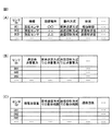
図3(A)〜図3(C)は、警備装置10の記憶部15に記憶される各種テーブルの例を示す図である。
FIG. 3A to FIG. 3C are diagrams illustrating examples of various tables stored in the
図3(A)は、センサ情報テーブルの一例を示す。センサ情報テーブルは、警備装置10に登録されている各センサ20について、例えば、センサID、センサの種類、センサの設置場所、センサの動作方式、及びセンサの状態などを対応付けたテーブル情報である。センサの種類には、例えば、防犯センサ、防災センサ及び非常ボタンの3種類がある。センサの動作方式には、センサ20が状態変化したときにその状態変化を警備装置10に通知する常時送信方式と、センサ20が状態変化してもその状態変化の通知を抑制する送信抑制方式がある。
FIG. 3A shows an example of a sensor information table. The sensor information table is table information in which, for each
センサの状態には、例えば、「非感知状態」(第1の状態の一例)と「感知状態」(第2の状態の一例)がある。例えば、防犯センサについては、非感知状態と感知状態は、それぞれ、扉などの開放又は人の存在が感知されていない状態と感知されている状態に対応する。また、防災センサについては、非感知状態と感知状態は、それぞれ、煙又は熱などが感知されていない状態と感知されている状態に対応する。また、非常ボタンについては、非感知状態と感知状態は、それぞれ、そのボタンが押下されていない状態と押下されている状態に対応する。なお、センサの状態は、非感知状態と感知状態に限らず、例えば、「機器異常」、「要注意」(感知状態と非感知状態の中間状態)などを含んでもよい。 The sensor states include, for example, a “non-sensing state” (an example of a first state) and a “sensing state” (an example of a second state). For example, for a security sensor, the non-sensing state and the sensing state correspond to a state in which a door or the like is opened or a presence of a person is not sensed and a sensed state, respectively. Regarding the disaster prevention sensor, the non-sensing state and the sensing state correspond to a state where smoke or heat is not sensed and a state where it is sensed, respectively. For the emergency button, the non-sensing state and the sensing state correspond to a state where the button is not pressed and a state where the button is pressed, respectively. The sensor state is not limited to the non-sensing state and the sensing state, and may include, for example, “apparatus abnormality”, “attention required” (intermediate state between the sensing state and the non-sensing state), and the like.
図3(B)は、消費電力特性テーブルの一例を示す。消費電力特性テーブルは、センサ情報テーブルに含まれる各センサ20について、例えば、センサID、1回の通信での消費電力、常時送信方式での単位時間当たりの消費電力、及び送信抑制方式での単位時間当たりの消費電力などを対応付けたテーブル情報である。これらの情報は、警備装置10が各センサ20の動作方式を決定する際に参照される。
FIG. 3B shows an example of the power consumption characteristic table. For each
図3(C)は、電力履歴情報テーブルの一例を示す。電力履歴情報テーブルは、センサ情報テーブルに含まれる各センサ20について、例えば、センサID、残電池容量、常時送信方式での累積動作時間、送信抑制方式での累積動作時間、及び警備装置10との通信回数などを対応付けたテーブル情報である。これらの情報は、各センサ20の動作方式を決定する際に制御部16により参照され、随時更新される。なお、常時送信方式での累積動作時間と送信抑制方式での累積動作時間は、動作方式の履歴情報の一例である。
FIG. 3C shows an example of the power history information table. For each
制御部16は、CPU、ROM及びRAMなどを含むマイクロコンピュータ並びにその周辺回路で構成され、上述した各部を制御して警備装置10を動作させる。
The
図4は、警備装置10の制御部16の機能ブロック図である。制御部16は、上記のマイクロコンピュータ及びマイクロコンピュータ上で実行されるコンピュータプログラムによって実現される機能モジュールとして、状態問合せ部161と、モード設定部162と、異常判定部163と、通報部164と、動作方式決定部165とを有する。
FIG. 4 is a functional block diagram of the
状態問合せ部161は、操作部13が操作されて監視モードへのモード変更又は各センサ20の状態確認が指示されたときに、センサ20のうち、記憶部15のセンサ情報テーブルに送信抑制方式が記憶されているセンサに対してセンサI/F12を介して状態問合せを行う。そして、状態問合せ部161は、そのセンサの現在の状態を受信し、センサ情報テーブルに記憶されているセンサの状態と現在の状態が異なっていたときには、センサ情報テーブルの情報を更新する。後述するように、各センサ20は、送信抑制方式にて動作しているときには、状態変化があっても警備装置10へのその状態変化の通知を抑制する。したがって、センサ情報テーブルに送信抑制方式が記憶されているセンサ20については、センサ情報テーブルに記憶されているセンサの状態が現在も継続している場合と、その後そのセンサ20には状態変化が起こったがその状態変化の通知が抑止されている場合との2通りの可能性がある。このため、状態問合せ部161は、送信抑制方式にて動作するセンサ20に対して状態問合せを行って、そのセンサの現在の状態を確認する。
When the
一方、センサ情報テーブルに常時送信方式が記憶されているセンサ20については、状態変化があるたびにその状態変化が通知されるため、状態問合せ部161は、それらのセンサ20に対して状態問合せを行わない。このように、状態を問い合わせるセンサ数を制限することにより、状態問合せ部161は、状態問合せに要する時間を短縮させる。
On the other hand, for the
モード設定部162は、操作部13が操作されて警備装置10のモード変更が指示されたときに、警備装置10のモードを監視モード又は解除モードに切替え設定し、新たなモードを記憶部15に記憶する。これにより、警備装置10は、設定された新たなモードに従って動作する。
The
ただし、モード設定部162は、監視モードへのモード変更時には、記憶部15のセンサ情報テーブルに送信抑制方式が記憶されているセンサ20に対して状態問合せ部161が状態問合せを行った結果、センサ情報テーブルに記憶されている全てのセンサの状態が非感知状態であったときに限り、そのモード変更を許容する。このとき、モード設定部162は、報知部14を制御して、モード変更が可能である旨を利用者に報知する。一方、センサ情報テーブルに記憶されているセンサ20のうち、状態が感知状態であるセンサがあったならば、モード設定部162は、そのモード変更を許容せず、報知部14を制御して、対象のセンサの設置場所と併せて、モード変更が不可である旨を利用者に報知する。なお、モード設定部162は、解除モードなど、監視モード以外のモードへの変更時には、各センサ20の状態にかかわらず、そのモード変更を許容する。
However, when the
異常判定部163は、センサ20から感知信号を受信すると、センサ情報テーブルを参照して、受信された感知信号に含まれるセンサIDと対応付けられたセンサの種類を特定する。また、異常判定部163は、記憶部15に保持されている警備装置10の現在のモードを参照する。そして、異常判定部163は、警備装置10が監視モードに設定されているときに、防犯センサ、防災センサ又は非常ボタンの何れかから感知信号を受信すると、異常であると判定する。また、異常判定部163は、警備装置10が解除モードに設定されているときに、防災センサ又は非常ボタンから感知信号を受信すると、異常であると判定する。また、異常判定部163は、警備装置10が解除モードに設定されているときに、防犯センサから感知信号を受信すると、異常でないと判定する(即ち、その感知信号を無視する)。
When the
通報部164は、異常判定部163が異常であると判定したときに、センタ通信部11を介して異常信号をセンタ装置41に送信する。異常信号には、例えば、記憶部15に記憶された警備装置10のID、異常を感知したセンサのセンサID、並びにセンサ情報テーブルから特定されるそのセンサの種類及び設置場所などの情報が含まれる。
The
動作方式決定部165は、例えば、操作部13が操作されて警備装置10のモード変更が指示されたときに、各センサ20の動作方式を決定し、その動作方式を各センサ20に通知する処理(「動作方式決定処理」という)を実行する。監視モード以外のモードへの変更が指示されたときには、動作方式決定部165は、常時送信方式又は送信抑制方式での残り駆動可能時間の推定値が小さいセンサであるほど優先的に送信抑制方式となるように、複数のセンサ20の動作方式を決定する。一方、監視モードへの変更が指示されたときには、動作方式決定部165は、例えば全てのセンサ20の動作方式を常時送信方式に決定する。そして、動作方式決定部165は、決定した各センサ20の動作方式を、センサ情報テーブルに記憶するとともに、センサI/F12を介して各センサ20に通知する。
For example, when the
なお、動作方式決定部165は、モード変更時にかかわらず、例えば1日1回などのように定期的に、動作方式決定処理を実行してもよい。また、動作方式決定部165は、監視モードへの変更が指示されたときであっても、監視モード以外のモードへの変更のときと同様に、残り駆動可能時間の推定値が小さいセンサであるほど優先的に送信抑制方式となるように、複数のセンサ20の動作方式を決定してもよい。
Note that the operation
動作方式決定部165は、各センサ20の残り駆動可能時間を推定するために、例えば、記憶部15の消費電力特性テーブルと電力履歴情報テーブルを参照し、各センサ20について、動作方式の履歴情報、通信回数、消費電力特性及び電池容量から、次の(1)式により残電池容量を算出する。
B=B0−P=B0−(Ct×At+M1×Pt1+M2×Pt2) ・・・(1)
そして、動作方式決定部165は、算出した残電池容量の値を電力履歴情報テーブルに記憶して、情報を更新する。
The operation
B = B 0 −P = B 0 − (C t × A t + M 1 × P t1 + M 2 × P t2 ) (1)
Then, the operation
(1)式において、Bは現在の残電池容量、B0は電池容量の初期値、Pはセンサの動作開始時から現在までの消費電力量である。また、Ctは警備装置10との通信回数、Atは1回の通信での消費電力であり、括弧内の第1項は、警備装置10との通信による消費電力に相当する。また、M1は常時送信方式での単位時間当たりの消費電力、Pt1は常時送信方式での累積動作時間であり、括弧内の第2項は、常時送信方式での動作時における消費電力に相当する。また、M2は送信抑制方式での単位時間当たりの消費電力、Pt2は送信抑制方式での累積動作時間であり、括弧内の第3項は、送信抑制方式での動作時における消費電力に相当する。なお、(1)式では、センサ20の感知動作による消費電力も、常時送信方式での消費電力又は送信抑制方式での消費電力に含めている。
In equation (1), B is the current remaining battery capacity, B 0 is the initial value of the battery capacity, and P is the power consumption from the start of sensor operation to the present. Also, C t is the number of times of communication between the
常時送信方式又は送信抑制方式での残り駆動可能時間の推定値は、B/M1又はB/M2である。残電池容量が少ないほど残り駆動可能時間の推定値は小さいと考えられるため、動作方式決定部165は、残電池容量が少ないセンサであるほど優先的に送信抑制方式となるように、複数のセンサの動作方式を決定する。
The estimated value of the remaining driveable time in the constant transmission method or the transmission suppression method is B / M 1 or B / M 2 . Since the estimated value of the remaining driveable time is considered to be smaller as the remaining battery capacity is smaller, the operation
あるいは、動作方式決定部165は、(1)式に代えて、次の(2)式により残電池容量を算出してもよい。
Bn=Bn−1−P=Bn−1−(Ct×At+M×Pt) ・・・(2)
ここで、Bnは現在の残電池容量、Bn−1は前回算出された残電池容量、PはBn−1の算出時から現在までの消費電力量である。ただし、初回のBnは電池容量の初期値B0とする。また、Mは現在の動作方式での単位時間当たりの消費電力、Ptは前回残電池容量が算出されてから現在までの経過時間である。(2)式を使用する場合、記憶部15の電力履歴情報テーブルには、センサID、現在の残電池容量、前回算出された残電池容量、警備装置10との通信回数、及び前回の残電池容量の更新時刻を記憶しておけばよい。
Alternatively, the operation
B n = B n−1 −P = B n−1 − (C t × A t + M × P t ) (2)
Here, Bn is the current remaining battery capacity, Bn-1 is the remaining battery capacity calculated last time, and P is the power consumption from the time Bn-1 is calculated to the present. However, the initial B n is the initial value B 0 of the battery capacity. Further, M is the power consumption per unit time in the current operation method, and P t is the elapsed time from the previous calculation of the remaining battery capacity. When the expression (2) is used, the power history information table of the
例えばリチウム電池は、電池寿命が長く、長期間にわたって電圧がほぼ一定に保たれるが、残電池容量が少なくなると電圧が急激に低下するという特性がある。このため、センサ20の電池としてリチウム電池を使用する場合には、動作方式決定部165は、例えば上記の(1)式又は(2)式により、各センサ20の残電池容量を算出する。ただし、例えばアルカリ電池のように、残電池容量が少なくなるにつれて電圧が徐々に低下する電池は、電圧の値から現在の残電池容量を推定することができる。このため、そのような電池をセンサ20に使用する場合は、動作方式決定部165は、上記の(1)式又は(2)式のような計算を行わずに、現在の電圧値に基づいて推定された残電池容量を各センサ20から直接取得してもよい。
For example, a lithium battery has a long battery life and a voltage that is maintained almost constant over a long period of time. However, when the remaining battery capacity is reduced, the voltage rapidly decreases. For this reason, when a lithium battery is used as the battery of the
また、動作方式決定部165は、状態問合せ部161が状態問合せを予め定められた時間内に実行可能であるように、送信抑制方式にて動作させるセンサの総数を制限する。センサの電池寿命を長期化させるためには、多くのセンサ20を低消費電力の送信抑制方式にすればよいが、監視モードへの移行時などに行われる状態確認に要する時間を短くする必要もあるため、送信抑制方式にできるセンサ数には限りがある。そこで、警備装置10では、利用者の利便性を考慮して、監視モードへの移行時などに状態確認が例えば3秒以内で行われるように、状態問合せ部161による状態問合せ時間に予め上限値を設定しておく。そして、動作方式決定部165は、状態問合せ時間の上限値に応じて、送信抑制方式にて動作させるセンサ20の総数にも上限値を設定しておき、送信抑制方式となるセンサ20の総数がその上限値を超えないように、各センサ20の動作方式を決定する。例えば、動作方式決定部165は、算出された残電池容量が少ない順にその上限値以下の個数のセンサ20を選択して送信抑制方式とし、残りのセンサ20を常時送信方式とする。これにより、状態確認に要する時間を上限値以下にするとともに、全体的に見て、各センサ20の消費電力量を抑えることができる。
In addition, the operation
なお、動作方式決定部165は、各センサ20の残電池容量までを算出せずに、(1)式又は(2)式における現在までの消費電力量Pを算出し、その値から各センサ20の残り駆動可能時間を推定してもよい。この場合、常時送信方式又は送信抑制方式での残り駆動可能時間の推定値は、例えば(1)式の記号を用いてB0−P/M1又はB0−P/M2と表される。消費電力量Pが多いほど残り駆動可能時間の推定値は小さいと考えられるため、動作方式決定部165は、消費電力量が多いセンサであるほど優先的に送信抑制方式となるように、複数のセンサの動作方式を決定してもよい。この場合、動作方式決定部165は、算出された消費電力量が多い順に、上限値以下の個数のセンサ20を選択して送信抑制方式とし、残りのセンサ20を常時送信方式とすればよい。
In addition, the operation
あるいは、動作方式決定部165は、送信抑制方式にて動作した期間が短いセンサであるほど優先的に送信抑制方式となるように、複数のセンサの動作方式を決定してもよい。送信抑制方式にて動作した期間が短いセンサであるほど、消費電力量が多い常時送信方式にて動作した期間が長いため、残り駆動可能時間の推定値は小さいと考えられる。このため、動作方式決定部165は、記憶部15の電力履歴情報テーブルを参照して、送信抑制方式での累積動作時間が短い順に、上限値以下の個数のセンサ20を選択して送信抑制方式とし、残りのセンサ20を常時送信方式としてもよい。なお、この場合は、動作方式決定部165は、上記の残電池容量又は消費電力量を算出しなくてもよい。
Alternatively, the operation
あるいは、動作方式決定部165は、警備装置10との通信回数が多いセンサであるほど優先的に送信抑制方式となるように、複数のセンサの動作方式を決定してもよい。警備装置10との通信回数が多いセンサであるほど、その通信により多くの電力を消費しているため、残り駆動可能時間の推定値は小さいと考えられる。このため、動作方式決定部165は、記憶部15の電力履歴情報テーブルを参照して、警備装置10との通信回数が多い順に、上限値以下の個数のセンサ20を選択して送信抑制方式とし、残りのセンサ20を常時送信方式としてもよい。この場合も、動作方式決定部165は、上記の残電池容量又は消費電力量を算出しなくてもよい。
Alternatively, the operation
なお、送信抑制方式での累積動作時間から残り駆動可能時間を推定する場合に、その累積動作時間が同程度のセンサ20が複数あったときは、動作方式決定部165は、警備装置10との通信回数が多いセンサを優先的に送信抑制方式としてもよい。
In addition, when estimating the remaining driveable time from the accumulated operation time in the transmission suppression method, if there are a plurality of
このように、各センサ20の残り駆動可能時間の推定値として、残電池容量、消費電力量、送信抑制方式での累積動作時間、又は警備装置10との通信回数を用いて、動作方式決定部165は各センサ20の動作方式を決定する。これにより、警備装置10は、残り駆動可能時間の推定値が小さいセンサを、消費電力量が少ない送信抑制方式にて動作させて、各センサ20の電池寿命を平準化させる。なお、各センサ20の残り駆動可能時間の推定値として残電池容量を用いる場合には、各センサ20の初期の電池容量が異なっていても、より厳密に各センサ20の電池寿命を平準化させることができる。
Thus, as an estimated value of the remaining driveable time of each
図5は、センサ20の概略構成図である。センサ20は、センシング部21と、無線通信部22と、記憶部23と、制御部24とを有する。
FIG. 5 is a schematic configuration diagram of the
センシング部21は、センサ20の監視方向から入力される物理量に基づき、そのセンサが対象とする事象を感知する。センサ20が防犯センサであれば、センシング部21は、例えば、赤外線により人の存在を感知する熱線センサ、超音波により人の存在を感知するセンサ、入力画像から人の存在を感知する画像センサ、及び磁界の変化を感知して扉の開放を感知する近接センサなど、人の存在や建物の破壊を感知する公知の感知手段で構成される。また、センサ20が防災センサであれば、センシング部21は、例えば煙又は熱を感知する公知の感知手段で構成される。また、センサ20が非常ボタンであれば、センシング部21はスイッチで構成される。
The
無線通信部22は、警備装置10と無線信号を送受信するためのアンテナと、そのアンテナに接続される通信制御部とを備える。無線通信部22は、特定小電力無線などの通信規格に従って、警備装置10との間で通信を行う。無線通信部22から警備装置10に送信される無線信号には、少なくとも記憶部23に記憶された自己のセンサID及び通信アドレスが含まれる。無線通信部22は、コントローラとの間で通信を行うセンサ通信部として機能する。
The
無線通信部22は、センサ20の消費電力量を抑えるために、警備装置10から送信される信号を間欠受信によって受信する。例えば、無線通信部22は、通信レートに応じて決まる数十ミリ秒程度の受信状態と、数秒程度の切断状態とを交互に繰り返し、受信状態にあるときに、警備装置10からの信号を受信する。
The
記憶部23は、ROM、RAM又はHDDにて構成され、センサ20を動作させるための各種データ及び各種プログラムなどを記憶する。例えば、記憶部23は、センサ20の状態、センサID、通信アドレス、間欠受信間隔などを記憶する。また、記憶部23は、警備装置10から通知された動作方式(常時送信方式又は送信抑制方式)を記憶する。
The
制御部24は、CPU、ROM及びRAMなどを含むマイクロコンピュータ並びにその周辺回路で構成され、上述した各部を制御してセンサ20を動作させる。
The
図6は、センサ20の制御部24の機能ブロック図である。制御部24は、上記のマイクロコンピュータ及びマイクロコンピュータ上で実行されるコンピュータプログラムによって実現される機能モジュールとして、状態通知部241と、送信抑止部242と、状態回答部243とを有する。
FIG. 6 is a functional block diagram of the
状態通知部241は、センシング部21が対象の事象を感知して非感知状態から感知状態に変化したときに、無線通信部22を介してその状態変化を警備装置10に通知する。即ち、状態通知部241は、センサ20が感知状態になったことを示す感知信号を警備装置10に送信させる。また、状態通知部241は、センシング部21が対象の事象を感知しなくなって感知状態から非感知状態に変化したときに、無線通信部22を介して警備装置10にその状態変化を通知する。即ち、状態通知部241は、センサ20が非感知状態になったことを示す非感知信号を警備装置10に送信させる。状態通知部241は、警備装置10からの指示に基づいて、常時送信方式又は送信抑制方式にて警備装置10への通知を行う。
When the
送信抑止部242は、記憶部23に記憶されている動作方式を参照し、センサ20の動作方式が送信抑制方式であるときに、状態通知部241による警備装置10への状態変化の通知を抑止する。即ち、センサ20が警備装置10から送信抑制方式を指示されているときは、送信抑止部242は、その間ずっと状態通知部241が状態変化の通知を行わないようにする。
The
あるいは、送信抑止部242は、センサ20の動作方式が送信抑制方式であり、且つ警備装置10のモードが監視モード以外であるときに、状態通知部241による警備装置10への状態変化の通知を抑止してもよい。即ち、センサ20が送信抑制方式を指示されているときであっても、警備装置10のモードが監視モードであるときは、感知対象の事象を速やかに警備装置10に通知するため、送信抑止部242は、状態通知部241による通知の抑止を行わなくてもよい。この場合、警備装置10は、モード設定部162が警備装置10のモードを変更するたびに、新たなモードを各センサ20に通知しておく。そして、センサ20では、動作方式とともに警備装置10のモードを記憶部23に記憶しておき、送信抑止部242が記憶部23に記憶されている動作方式と警備装置10のモードを参照して、状態通知部241による通知を抑止するか否かを判定すればよい。
Alternatively, the
あるいは、送信抑止部242は、センサ20の動作方式が送信抑制方式であるときに、警備装置10のモードにかかわらず、センサ20が非感知状態から感知状態に状態変化したことに応じて、状態通知部241による新たな状態変化の通知を一定期間抑止してもよい。この場合、例えば、送信抑止部242は、センサ20が感知状態に変化した後、センサ20が非感知状態に変化してその非感知状態が予め定められた期間だけ継続するまで、状態通知部241による新たな状態変化の通知を抑止する。これを受けて、状態通知部241は、送信抑止部242による抑止が終了したときに、感知状態から非感知状態への状態変化を通知する。
Alternatively, when the operation method of the
なお、送信抑止部242は、センサ20の動作方式が送信抑制方式であるときに、センサが感知状態に変化した後、予め定められた期間だけ状態通知部241による新たな状態変化の通知を抑止し、状態通知部241は、送信抑止部242による抑止が終了したときに、感知状態から非感知状態への状態変化を通知してもよい。また、この場合、送信抑止部242は、センサ20について単位時間当たりの状態変化の頻度を計数し、その頻度が高いほど、上記の予め定められた長さの抑止期間を長い期間に設定してもよい。
The
状態回答部243は、警備装置10からの状態問合せに応じて、無線通信部22を介してセンサ20の現在の状態を警備装置10に通知する。センサ20の動作方式が送信抑制方式であるときには、送信抑止部242が状態通知部241による状態変化の通知を抑止するため、警備装置10がセンサ20の現在の状態を知るために、センサ20は警備装置10から状態問合せを受信することがある。状態回答部243は、センサ20の動作方式にかかわらず、この状態問合せに対して、センサ20の現在の状態を警備装置10に通知する。
The
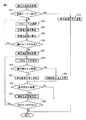
図7は、警備装置10の動作方式決定処理の動作例を示したフローチャートである。図7に示すフローは、警備装置10の操作部13が操作されて警備装置10のモード変更が指示されたときに、記憶部15に予め記憶されたプログラムに従って、制御部16により実行される。
FIG. 7 is a flowchart illustrating an operation example of the operation method determination process of the
警備装置10のモード変更が指示されると、まず、モード設定部162は、そのモード変更が監視モードへの変更か否かを判定する(ステップS11)。監視モードへの変更である場合(ステップS11でYes)には、動作方式決定部165は、例えば全てのセンサ20について、動作方式を常時送信方式に決定し、新たな動作方式をセンサ情報テーブルに記憶するとともに、その新たな動作方式を各センサ20に通知する(ステップS12)。これにより、動作方式決定処理は終了する。
When the mode change of the
一方、監視モード以外のモードへの変更である場合(ステップS11でNo)には、動作方式決定部165は、センサ情報テーブルに記憶されているセンサ20のうちの1つを選択する(ステップS13)。次に、動作方式決定部165は、消費電力特性テーブルと電力履歴情報テーブルを参照することにより、例えば上記の(1)式又は(2)式を用いて、そのセンサについて、消費電力量を算出し(ステップS14)、残電池容量を算出する(ステップS15)。このとき、動作方式決定部165は、算出した残電池容量の値を電力履歴情報テーブルに記憶する。
On the other hand, when the mode is changed to a mode other than the monitoring mode (No in step S11), the operation
そして、動作方式決定部165がまだ残電池容量を算出していないセンサ20がある場合には(ステップS16でYes)、動作フローはステップS13に戻る。この場合、動作方式決定部165は、他のセンサ20について上記のステップS13〜S16の動作を実行する。
If there is a
一方、全てのセンサ20について残電池容量を算出した場合には(ステップS16でNo)、動作方式決定部165は、再度電力履歴情報テーブルを参照し、残電池容量が少ない順に、各センサ20に優先順位を割り当てる(ステップS17)。
On the other hand, when the remaining battery capacities are calculated for all the sensors 20 (No in step S16), the operation
次に、動作方式決定部165は、センサ情報テーブルに記憶されているセンサ20のうちの1つを選択し(ステップS18)、そのセンサに割り当てられた優先順位が、送信抑制方式とするセンサ数の上限値以下であるか否かを判定する(ステップS19)。そのセンサの優先順位が上限値以下である場合(ステップS19でYes)には、動作方式決定部165は、そのセンサの動作方式を送信抑制方式と決定する(ステップS20)。一方、そのセンサの優先順位が上限値より大きい場合(ステップS19でNo)には、動作方式決定部165は、そのセンサの動作方式を常時送信方式と決定する(ステップS21)。
Next, the operation
次に、ステップS20又はS21により対象のセンサの動作方式が変更される場合(ステップS22でYes)には、動作方式決定部165は、そのセンサの新たな動作方式を、センサ情報テーブルに記憶するとともに、そのセンサに通知する(ステップS23)。一方、ステップS20又はS21により対象のセンサの動作方式が変更されない場合(ステップS22でNo)には、ステップS23は実行されず、動作フローは次に進む。
Next, when the operation method of the target sensor is changed in step S20 or S21 (Yes in step S22), the operation
そして、動作方式決定部165がまだ動作方式を決定していないセンサ20がある場合には(ステップS24でYes)、動作フローはステップS18に戻る。この場合、動作方式決定部165は、他のセンサ20について上記のステップS18〜S23の動作を実行する。一方、動作方式決定部165が全てのセンサ20について動作方式を決定した場合には(ステップS24でNo)、動作方式決定処理は終了する。
If there is a
なお、動作方式決定部165は、モード変更時にかかわらず、例えば1日1回などのように定期的に、動作方式決定処理を実行してもよい。この場合、上記のステップS11及びS12の動作は実行されない。また、動作方式決定部165が送信抑制方式での累積動作時間又は警備装置10との通信回数から動作方式を決定する場合には、残電池容量の算出は不要であるため、上記のステップS13〜S16は省略可能である。
Note that the operation
図8は、警備装置10が監視モードへのモード変更の可否を判定する処理(モード変更判定処理)の動作例を示したフローチャートである。図8に示すフローは、警備装置10の操作部13が操作されて監視モードへのモード変更が指示されたときに、記憶部15に予め記憶されたプログラムに従って、制御部16により実行される。
FIG. 8 is a flowchart illustrating an operation example of processing (mode change determination processing) in which the
監視モードへのモード変更が指示されると、まず、モード設定部162は、記憶部15のセンサ情報テーブルに記憶されているセンサ20のうちの1つについて、その動作方式を確認する(ステップS31)。ステップS31で確認されたセンサ20の動作方式が送信抑制方式であれば(ステップS32でYes)、状態問合せ部161は、センサI/F12を介してそのセンサ20に状態問合せを行う(ステップS33)。これにより、状態問合せ部161は、そのセンサ20の現在の状態を受信して、受信された状態を記憶部15のセンサ情報テーブルに記憶する。一方、ステップS31で確認されたセンサ20の動作方式が常時送信方式であれば(ステップS32でNo)、状態問合せ部161が状態問合せを行わずに、動作フローはステップS34に進む。
When the mode change to the monitoring mode is instructed, first, the
そして、モード設定部162は、まだ動作方式を確認していないセンサ20があるか否かを判定する(ステップS34)。まだ動作方式を確認していないセンサ20がある場合には(ステップS34でYes)、動作フローはステップS31に戻り、モード設定部162は他のセンサについて上記の各ステップの動作を実行する。一方、記憶部15に記憶されている全てのセンサ20について動作方式を確認した場合には(ステップS34でNo)、モード設定部162は、再び記憶部15のセンサ情報テーブルを参照し、感知状態が記憶されているセンサ20があるか否かを確認する(ステップS35)。
And the
感知状態が記憶されているセンサ20がある場合には(ステップS35でYes)、モード設定部162は、監視モードへのモード変更を許容せず、モード変更が不可である旨を利用者に報知する(ステップS36)。このとき、モード設定部162は、感知状態が記憶されているセンサ20と、センサ情報テーブルから特定されるその設置場所も、併せて利用者に報知する。一方、感知状態が記憶されているセンサ20がない場合には(ステップS35でNo)、モード設定部162は、監視モードへのモード変更を許容して、モード変更が可能である旨を利用者に報知する(ステップS37)。これにより、モード設定部162は、動作を終了する。
When there is a
以上説明したように、警備装置10は、残り駆動可能時間の推定値が小さいセンサであるほど優先的に送信抑制方式となるように各センサの動作方式を決定し、センサ20は、警備装置10からの指示に基づき常時送信方式又は送信抑制方式にて警備装置10への通知を行う。また、警備装置10は、送信抑制方式にて動作しているセンサに対して状態問合せを行って、そのセンサの現在の状態を受信する。これにより、警備システム1では、状態問合せに要する時間を短縮させ、センサの電池を長寿命化させるとともに、各センサの残電池容量を平準化させて電池交換に要する運用コストを削減することが可能になる。
As described above, the
なお、上記では、通信システムの一例として警備システム1を説明したが、通信システムは、異常を感知して監視センタに通報する警備システムに限らず、例えば扉の開閉状態などを示す各センサの状態をコントローラで確認するものであってもよい。
In the above description, the
1 警備システム
10 警備装置
12 センサI/F
15 記憶部
16 制御部
161 状態問合せ部
162 モード設定部
163 異常判定部
164 通報部
165 動作方式決定部
20 センサ
21 センシング部
22 無線通信部
23 記憶部
24 制御部
241 状態通知部
242 送信抑止部
243 状態回答部
1
DESCRIPTION OF
Claims (7)
前記複数のセンサのそれぞれは、
前記コントローラとの間で通信を行うセンサ通信部と、
前記コントローラからの指示に基づいて、当該センサが第1の状態から第2の状態又は第2の状態から第1の状態に状態変化したときに前記センサ通信部を介して当該状態変化を前記コントローラに通知する常時送信方式、及び当該状態変化があっても当該状態変化の通知を抑制する送信抑制方式の何れかの動作方式にて、前記コントローラへの通知を行う状態通知部と、
前記コントローラからの状態問合せに応じて、前記センサ通信部を介して当該センサの現在の状態を前記コントローラに通知する状態回答部と、
を有し、
前記コントローラは、
前記複数のセンサとの間で通信を行う通信部と、
前記複数のセンサのそれぞれについて、当該センサから受信された当該センサの状態、及び当該センサの現在の動作方式を記憶する記憶部と、
残り駆動可能時間の推定値が小さいセンサであるほど優先的に前記送信抑制方式となるように前記複数のセンサの動作方式を決定し、前記通信部を介してそれぞれのセンサに決定された動作方式を通知する動作方式決定部と、
前記複数のセンサのうち、前記常時送信方式にて動作しているセンサに対して状態問合せを行わず、前記送信抑制方式にて動作しているセンサに対して前記通信部を介して状態問合せを行って、当該センサの現在の状態を受信する状態問合せ部と、
を有することを特徴とする通信システム。 A communication system including a plurality of sensors and a controller capable of communicating with each other,
Each of the plurality of sensors is
A sensor communication unit that communicates with the controller;
Based on an instruction from the controller, when the sensor changes from the first state to the second state or from the second state to the first state, the controller changes the state via the sensor communication unit. A state notification unit that performs notification to the controller in any one of the operation method of the continuous transmission method that notifies the state change and the transmission suppression method that suppresses the notification of the state change even if there is the state change;
In response to a status inquiry from the controller, a status answering unit for notifying the controller of the current status of the sensor via the sensor communication unit,
Have
The controller is
A communication unit for communicating with the plurality of sensors;
For each of the plurality of sensors, a storage unit that stores the state of the sensor received from the sensor and the current operation method of the sensor;
The operation method of the plurality of sensors is determined so as to preferentially become the transmission suppression method as the estimated value of the remaining driveable time is smaller, and the operation method determined for each sensor via the communication unit An operation method determination unit for notifying
Among the plurality of sensors, the state inquiry is not made to the sensor operating in the constant transmission method, and the state inquiry is made to the sensor operating in the transmission suppression method via the communication unit. And a status inquiry unit that receives the current status of the sensor,
A communication system comprising:
前記コントローラは、
前記複数のセンサにより監視領域を監視する監視モードを含む複数のモードの何れかに設定可能であり、
前記監視モードへのモード変更時に、前記状態問合せ部が状態問合せを行った結果、前記記憶部に記憶されている全てのセンサの状態が第1の状態であったならば当該モード変更を許容するモード設定部を更に有する、請求項1に記載の通信システム。 The first state is a non-sensing state of the sensor, and the second state is a sensing state of the sensor,
The controller is
It can be set to any of a plurality of modes including a monitoring mode for monitoring a monitoring area by the plurality of sensors,
At the time of changing the mode to the monitoring mode, if the state inquiry unit makes a state inquiry, and if all the sensors stored in the storage unit are in the first state, the mode change is allowed. The communication system according to claim 1, further comprising a mode setting unit.
前記動作方式決定部は、前記送信抑制方式にて動作した期間が短いセンサであるほど残り駆動可能時間を小さく推定する、請求項1又は2に記載の通信システム。 The storage unit further stores history information of an operation method instructed by the operation method determination unit to the plurality of sensors,
The communication system according to claim 1, wherein the operation method determination unit estimates the remaining driveable time to be smaller as the sensor operates in the transmission suppression method.
前記動作方式決定部は、通信回数が多いセンサであるほど残り駆動可能時間を小さく推定する、請求項1〜3の何れか一項に記載の通信システム。 The storage unit further stores the number of communication between the communication unit and the plurality of sensors for each sensor,
The communication system according to any one of claims 1 to 3, wherein the operation method determination unit estimates the remaining drivable time to be smaller as the sensor has a higher communication count.
前記動作方式決定部は、前記動作方式の履歴情報、前記通信回数及び前記消費電力特性から前記複数のセンサの消費電力量を算出し、当該消費電力量が多いセンサであるほど残り駆動可能時間を小さく推定する、請求項1又は2に記載の通信システム。 The storage unit further stores history information of the operation method instructed to the plurality of sensors by the operation method determination unit, the number of communication between the communication unit and the plurality of sensors, and power consumption characteristics of the plurality of sensors. And
The operation method determination unit calculates the power consumption of the plurality of sensors from the history information of the operation method, the number of communication times, and the power consumption characteristics, and the remaining driveable time is calculated as the sensor has a higher power consumption. The communication system according to claim 1, wherein the communication system is estimated to be small.
前記動作方式決定部は、前記動作方式の履歴情報、前記通信回数、前記消費電力特性及び前記電池容量から前記複数のセンサの残電池容量を算出し、当該残電池容量が少ないセンサであるほど残り駆動可能時間を小さく推定する、請求項1又は2に記載の通信システム。 The storage unit includes history information on an operation method instructed to the plurality of sensors by the operation method determination unit, the number of times of communication between the communication unit and the plurality of sensors, and power consumption characteristics and battery capacity of the plurality of sensors. Remember more,
The operating method determination unit, history information of the operation system, the communication count, the power consumption characteristics and calculates the remaining battery capacity of the plurality of sensors from the battery capacity, the more in the remaining battery capacity is small sensor The communication system according to claim 1, wherein the remaining driveable time is estimated to be small.
Priority Applications (1)
| Application Number | Priority Date | Filing Date | Title |
|---|---|---|---|
| JP2013225530A JP6292820B2 (en) | 2013-10-30 | 2013-10-30 | Communications system |
Applications Claiming Priority (1)
| Application Number | Priority Date | Filing Date | Title |
|---|---|---|---|
| JP2013225530A JP6292820B2 (en) | 2013-10-30 | 2013-10-30 | Communications system |
Publications (2)
| Publication Number | Publication Date |
|---|---|
| JP2015088906A JP2015088906A (en) | 2015-05-07 |
| JP6292820B2 true JP6292820B2 (en) | 2018-03-14 |
Family
ID=53051283
Family Applications (1)
| Application Number | Title | Priority Date | Filing Date |
|---|---|---|---|
| JP2013225530A Active JP6292820B2 (en) | 2013-10-30 | 2013-10-30 | Communications system |
Country Status (1)
| Country | Link |
|---|---|
| JP (1) | JP6292820B2 (en) |
Families Citing this family (4)
| Publication number | Priority date | Publication date | Assignee | Title |
|---|---|---|---|---|
| JP6700938B2 (en) * | 2016-04-26 | 2020-05-27 | ホーチキ株式会社 | Management system |
| CN108123887B (en) | 2016-11-29 | 2020-01-03 | 新华三技术有限公司 | Message processing method and device |
| JP2018174448A (en) * | 2017-03-31 | 2018-11-08 | 富士通株式会社 | Communication device, data acquisition system, data acquisition control method |
| JP6997873B2 (en) | 2018-08-22 | 2022-01-18 | 株式会社Nttドコモ | Detection device |
Family Cites Families (4)
| Publication number | Priority date | Publication date | Assignee | Title |
|---|---|---|---|---|
| JP4665349B2 (en) * | 2001-06-29 | 2011-04-06 | パナソニック電工株式会社 | Wireless sensor system |
| JP2005079957A (en) * | 2003-09-01 | 2005-03-24 | Matsushita Electric Ind Co Ltd | Information apparatus and its controlling method and program |
| JP5108964B2 (en) * | 2011-01-14 | 2012-12-26 | 株式会社エヌ・ティ・ティ・ドコモ | Apparatus and method for calculating battery life of mobile device |
| JP5794123B2 (en) * | 2011-11-24 | 2015-10-14 | 富士通株式会社 | Server apparatus, communication control method, communication control program, and service system |
-
2013
- 2013-10-30 JP JP2013225530A patent/JP6292820B2/en active Active
Also Published As
| Publication number | Publication date |
|---|---|
| JP2015088906A (en) | 2015-05-07 |
Similar Documents
| Publication | Publication Date | Title |
|---|---|---|
| JP6292820B2 (en) | Communications system | |
| JP5504809B2 (en) | Security system and electronic photo frame | |
| JP2003115092A5 (en) | ||
| JP2003115092A (en) | Sensor network system managing method, sensor network system managing program, recording medium having sensor network system managing program recorded thereon, sensor network system managing device, managing method for relay network, relay network managing program, recording medium having relay network managing program recorded thereon and relay network managing device | |
| JP6680336B2 (en) | Monitored person monitoring system, terminal unit and computer program | |
| JP2010050664A (en) | Household electric appliance controller and program thereof | |
| JP2010049455A (en) | Residential control apparatus and residential alarm unit | |
| JP2018055293A (en) | Monitoring system, monitoring method, and monitoring program | |
| JP2009070118A (en) | Security device and monitoring mode switching control method | |
| JP6289031B2 (en) | Communications system | |
| JP5276893B2 (en) | Resident survival information notification system | |
| JP6184267B2 (en) | Wireless communication system and wireless controller | |
| JP4439929B2 (en) | Alarm device | |
| JP2019096331A (en) | Terminal device and program | |
| JP5170749B2 (en) | Residential monitoring system | |
| JP2017042275A (en) | In-house apparatus control system | |
| JP5538990B2 (en) | Security system and security system control method | |
| JP2019114107A (en) | Bathroom watching apparatus and method, external device and program | |
| JP3847760B2 (en) | Single person safety confirmation system, information processing apparatus, and single person residence monitoring method | |
| JP4428122B2 (en) | Security device and program | |
| JP5433092B2 (en) | Resident survival information notification system | |
| JP2005339099A (en) | Communication equipment and its program | |
| JP5723645B2 (en) | Transfer output device | |
| JP2005079957A (en) | Information apparatus and its controlling method and program | |
| AU2018317485B2 (en) | Passive care control method and associated systems |
Legal Events
| Date | Code | Title | Description |
|---|---|---|---|
| A621 | Written request for application examination |
Free format text: JAPANESE INTERMEDIATE CODE: A621 Effective date: 20160627 |
|
| A977 | Report on retrieval |
Free format text: JAPANESE INTERMEDIATE CODE: A971007 Effective date: 20170419 |
|
| A131 | Notification of reasons for refusal |
Free format text: JAPANESE INTERMEDIATE CODE: A131 Effective date: 20170523 |
|
| A521 | Request for written amendment filed |
Free format text: JAPANESE INTERMEDIATE CODE: A523 Effective date: 20170718 |
|
| TRDD | Decision of grant or rejection written | ||
| A01 | Written decision to grant a patent or to grant a registration (utility model) |
Free format text: JAPANESE INTERMEDIATE CODE: A01 Effective date: 20180116 |
|
| A61 | First payment of annual fees (during grant procedure) |
Free format text: JAPANESE INTERMEDIATE CODE: A61 Effective date: 20180213 |
|
| R150 | Certificate of patent or registration of utility model |
Ref document number: 6292820 Country of ref document: JP Free format text: JAPANESE INTERMEDIATE CODE: R150 |
|
| R250 | Receipt of annual fees |
Free format text: JAPANESE INTERMEDIATE CODE: R250 |
|
| R250 | Receipt of annual fees |
Free format text: JAPANESE INTERMEDIATE CODE: R250 |
|
| R250 | Receipt of annual fees |
Free format text: JAPANESE INTERMEDIATE CODE: R250 |
|
| R250 | Receipt of annual fees |
Free format text: JAPANESE INTERMEDIATE CODE: R250 |