以下、複数の実施形態による洗濯機について、図面を参照して説明する。なお、各実施形態において実質的に同一の構成部位には同一の符号を付し、説明を省略する。
(第一実施形態)
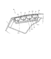
図1に示す洗濯機10は、乾燥機能を備えたドラム式洗濯乾燥機であって、洗濯機本体11、扉12、図2に示す制御手段としての制御装置20、及び操作パネル30を備えている。なお、洗濯機10において、扉12側を洗濯機10の前側とし、扉12と反対側を洗濯機10の後側とする。
Hereinafter, washing machines according to a plurality of embodiments will be described with reference to the drawings. In addition, in each embodiment, the same code | symbol is attached | subjected to the substantially same component, and description is abbreviate | omitted.
(First embodiment)
A washing machine 10 shown in FIG. 1 is a drum-type washing and drying machine having a drying function, and includes a washing machine main body 11, a door 12, a control device 20 as a control means shown in FIG. Yes. In the washing machine 10, the door 12 side is the front side of the washing machine 10, and the opposite side of the door 12 is the rear side of the washing machine 10.
洗濯機本体11は、洗濯機10の外殻を構成するもので、前面が滑らかに傾斜した矩形の箱状に形成されている。また、本実施形態の場合、洗濯機本体11は、白色を基調として構成されている。洗濯機本体11の前面中央部分には、開口111が設けられている。開口111は、洗濯機本体11の内部に設けられた図示しない回転槽に連通されており、洗濯物は、この開口111を通して回転槽内に出し入れされる。扉12は、開口111を開閉可能に設けられている。扉12は、扉ボタン13を操作されることにより開放される。洗濯機本体11の上面には、給水口14が設けられている。給水口14は、図示しない給水ホースによって水源となる水道の蛇口に接続される。そして、水道の蛇口からの水は、給水ホース及び給水口14を通って、洗濯機本体11内に設けられた図示しない水槽内へ供給される。
The washing machine body 11 constitutes the outer shell of the washing machine 10 and is formed in a rectangular box shape whose front surface is smoothly inclined. Moreover, in the case of this embodiment, the washing machine main body 11 is comprised based on white. An opening 111 is provided in the front central portion of the washing machine body 11. The opening 111 communicates with a rotating tub (not shown) provided inside the washing machine main body 11, and the laundry is put into and out of the rotating tub through the opening 111. The door 12 is provided so that the opening 111 can be opened and closed. The door 12 is opened by operating the door button 13. A water supply port 14 is provided on the upper surface of the washing machine body 11. The water supply port 14 is connected to a faucet serving as a water source by a water supply hose (not shown). And the water from the tap of a water supply is supplied into the water tank which is not shown in the figure provided in the washing machine main body 11 through the water supply hose and the water supply port 14. FIG.
制御装置20は、図2に示すように、モータ21、排水弁22、給水弁23、圧縮機24、及び送風機25などに接続されている。それぞれ詳細な説明は省略するが、モータ21は、洗濯機本体11内に設けた図示しない回転槽を回転させるためのものである。排水弁22は、図示しない水槽内の水を機外へ排水するためのものである。給水弁23は、給水口14と図示しない水槽内との連通を開閉し、水槽内へ給水を行うためのものである。圧縮機24は、乾燥機能用のヒートポンプユニットを構成するものである。送風機25は、ヒートポンプユニットにより生成された温風を図示しない回転槽内へ供給するためのものである。
As shown in FIG. 2, the control device 20 is connected to a motor 21, a drain valve 22, a water supply valve 23, a compressor 24, a blower 25, and the like. Although detailed explanation is omitted, the motor 21 is for rotating a rotating tub (not shown) provided in the washing machine body 11. The drain valve 22 is for draining water in a water tank (not shown) to the outside of the apparatus. The water supply valve 23 opens and closes communication between the water supply port 14 and the inside of a water tank (not shown), and supplies water into the water tank. The compressor 24 constitutes a heat pump unit for a drying function. The blower 25 is for supplying warm air generated by the heat pump unit into a rotating tank (not shown).
また、制御装置20は、温度センサ26、水位センサ27、回転センサ28、扉スイッチ29などの入力機器、及び操作パネル30に接続されている。それぞれ詳細な説明は省略するが、温度センサ26は、図示しない水槽内の温度を検出するものである。水位センサ27は、水槽内の水位を検出するものである。回転センサ28は、図示しない回転槽の回転位置及び回転速度を検出するものである。扉スイッチ29は、扉12の開閉を検出するものである。
The control device 20 is connected to input devices such as a temperature sensor 26, a water level sensor 27, a rotation sensor 28, a door switch 29, and an operation panel 30. Although detailed explanation is omitted for each, the temperature sensor 26 detects the temperature in a water tank (not shown). The water level sensor 27 detects the water level in the water tank. The rotation sensor 28 detects a rotation position and a rotation speed of a rotation tank (not shown). The door switch 29 detects opening / closing of the door 12.
操作パネル30は、洗濯機10の運転に関する各種設定を行うもので、図1に示すように、洗濯機本体11の上面前側に設けられている。操作パネル30は、図3及び図4に示すように、飾りパネル31、回路基板32、光源ホルダ33、複数の透明電極フィルム34、複数の圧接部材35、及び複数の光源36を有して構成されている。洗濯機本体11の上部前側には、該洗濯機本体11を矩形に窪ませて収容部112が形成されている。この収容部112内には、操作パネル30を構成する回路基板32、光源ホルダ33、複数の透明電極フィルム34、複数の圧接部材35、及び複数の光源36が収容されている。そして、飾りパネル31は、これら回路基板32、光源ホルダ33、複数の透明電極フィルム34、複数の圧接部材35、及び複数の光源36の上側を覆っている。
The operation panel 30 performs various settings related to the operation of the washing machine 10 and is provided on the front side of the upper surface of the washing machine body 11 as shown in FIG. 3 and 4, the operation panel 30 includes a decorative panel 31, a circuit board 32, a light source holder 33, a plurality of transparent electrode films 34, a plurality of press contact members 35, and a plurality of light sources 36. Has been. On the upper front side of the washing machine body 11, a housing portion 112 is formed by recessing the washing machine body 11 into a rectangular shape. In the housing portion 112, a circuit board 32, a light source holder 33, a plurality of transparent electrode films 34, a plurality of press contact members 35, and a plurality of light sources 36 constituting the operation panel 30 are housed. The decorative panel 31 covers the circuit board 32, the light source holder 33, the plurality of transparent electrode films 34, the plurality of press contact members 35, and the plurality of light sources 36.
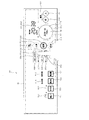
飾りパネル31は、操作パネル30の表面を構成している。飾りパネル31は、例えば樹脂などの板で構成され、全体として遮光性を有している。なお、飾りパネル31は、樹脂製に限られず、強化ガラスなどであってもよい。飾りパネル31には、図5に示すように、複数の操作部及び表示部として複数の文字及び図形が設けられている。この複数の文字及び図形のうち、「入」で示された電源入ボタン311、「切」で示された電源切ボタン312、及び「電源(オートパワーオフ)」で示された文字部313については、常に外部から視認可能に構成されている。
The decoration panel 31 constitutes the surface of the operation panel 30. The decorative panel 31 is made of, for example, a resin plate and has a light shielding property as a whole. The decorative panel 31 is not limited to resin, and may be tempered glass. As shown in FIG. 5, the decoration panel 31 is provided with a plurality of characters and figures as a plurality of operation units and a display unit. Among the plurality of characters and figures, the power on button 311 indicated by “ON”, the power OFF button 312 indicated by “OFF”, and the character portion 313 indicated by “POWER (auto power off)”. Is always visible from the outside.
一方、これら電源ボタン311、312の図形及び「電源(オートパワーオフ)」の文字部313以外の文字及び図形、すなわち図5に二点鎖線で示した切替表示領域40内に設けられた文字及び図形については、透過性を有して例えば半透明に構成されている。そして、切替表示領域40内に設けられた文字及び図形は、飾りパネル31の裏側から光が照射されることにより飾りパネル31に表示される。飾りパネル31の裏側から光が照射されていない状態では、当該文字及び図形は、飾りパネル31に表示されない。
On the other hand, characters and figures other than the figure of the power buttons 311 and 312 and the character part 313 of “power supply (auto power off)”, that is, letters provided in the switching display area 40 indicated by a two-dot chain line in FIG. The figure has transparency and is configured to be translucent, for example. The characters and figures provided in the switching display area 40 are displayed on the decorative panel 31 when light is irradiated from the back side of the decorative panel 31. In a state where light is not irradiated from the back side of the decorative panel 31, the characters and figures are not displayed on the decorative panel 31.
回路基板32は、図3に示すように、横長の矩形状に構成されている。また、回路基板32には、電子部品322や、7セグメントディスプレイ323及び複数の光源36などが実装されている。電子部品322は、例えばマイコンなどであって、図2に示す検出・表示回路321を構成している。7セグメントディスプレイ323や光源36は、飾りパネル31の切替表示領域40内に配置されている。光源36は、例えばLEDなどであり、飾りパネル31の切替表示領域40内に設けられた文字又は図形に対応して設けられている。7セグメントディスプレイ323や光源36は、検出・表示回路321を介して制御装置20に接続されている。この7セグメントディスプレイ323や光源36、及び検出・表示回路321は、表示部の表示及び非表示を切り替える表示手段として機能する。
As shown in FIG. 3, the circuit board 32 is configured in a horizontally long rectangular shape. In addition, an electronic component 322, a 7-segment display 323, a plurality of light sources 36, and the like are mounted on the circuit board 32. The electronic component 322 is, for example, a microcomputer and constitutes the detection / display circuit 321 shown in FIG. The 7-segment display 323 and the light source 36 are arranged in the switching display area 40 of the decorative panel 31. The light source 36 is, for example, an LED, and is provided corresponding to a character or a figure provided in the switching display area 40 of the decoration panel 31. The 7-segment display 323 and the light source 36 are connected to the control device 20 via the detection / display circuit 321. The 7-segment display 323, the light source 36, and the detection / display circuit 321 function as display means for switching between display and non-display of the display unit.
光源ホルダ33は、遮光性を有する例えば樹脂などの部材で構成され、ある程度の厚みを有している。光源ホルダ33は、個々の光源36に対応して複数の遮光部331を有している。遮光部331は、図4に示すように椀状の底部に穴332を有している。回路基板32に設けられた光源36は、この穴332から遮光部331内に挿入される。そして、ある遮光部331内において光源36から照射された光は、他の遮光部331へ漏れ出ないようになっている。
The light source holder 33 is made of a light-shielding member such as a resin and has a certain thickness. The light source holder 33 has a plurality of light shielding portions 331 corresponding to the individual light sources 36. As shown in FIG. 4, the light shielding portion 331 has a hole 332 in a bowl-shaped bottom portion. The light source 36 provided on the circuit board 32 is inserted into the light shielding portion 331 through the hole 332. The light emitted from the light source 36 in a certain light shielding part 331 is prevented from leaking out to other light shielding parts 331.
これにより、複数の光源36のうち一の光源36が発光すると、その発光した光源36に対応する飾りパネル31の文字又は図形が、飾りパネル31の切替表示領域40内においてその表面に浮かび上がるように表示される。この光源36は、三段階以上で輝度を調節可能に構成されている。そのため、飾りパネル31の切替表示領域40内に表示される文字又は図形は、その輝度が三段階以上に変更可能となっている。
Thus, when one of the plurality of light sources 36 emits light, the characters or figures of the decorative panel 31 corresponding to the emitted light source 36 appear on the surface in the switching display area 40 of the decorative panel 31. Is displayed. The light source 36 is configured so that the brightness can be adjusted in three or more stages. Therefore, the brightness of the characters or graphics displayed in the switching display area 40 of the decoration panel 31 can be changed in three or more levels.
透明電極フィルム34は、透光性を有するシート状の部材で構成されている。透明電極フィルム34は、静電容量の変化を検出するための検出電極として複数の検出部341を有している。透明電極フィルム34は、回路基板32の検出・表示回路321に接続されている。つまり、透明電極フィルム34の各検出部341は、検出・表示回路321を介して制御装置20に接続されている。
The transparent electrode film 34 is configured by a sheet-like member having translucency. The transparent electrode film 34 has a plurality of detection units 341 as detection electrodes for detecting a change in capacitance. The transparent electrode film 34 is connected to the detection / display circuit 321 of the circuit board 32. That is, each detection unit 341 of the transparent electrode film 34 is connected to the control device 20 via the detection / display circuit 321.
検出・表示回路321は、透明電極フィルム34の検出部341と使用者の例えば指との間の静電容量の変化を検出し、これにより使用者のタッチ操作を検出する。すなわち、透明電極フィルム34の検出部341は、飾りパネル31に対する使用者のタッチ操作を検出するタッチスイッチとして機能する。また、透明電極フィルム34及び検出・表示回路321は、操作パネル30の操作部に対するタッチ操作を検出する操作検出手段として機能する。検出・表示回路321は、3つの透明電極フィルム34の検出部341に対応して回路基板32上の3ヶ所に設けられており、検出部341による検出結果を制御装置20へ出力する。検出・表示回路321は、ノイズ防止のため透明電極フィルム34との接続距離が最短となるよう回路基板32とのコネクタ(図示せず)位置の近傍となるよう回路基板32の裏面側に設けられている
圧接部材35は、例えば弾性を有する透明な樹脂材料で構成されている。圧接部材35は、図3では右側の一部のみを示しているが透明電極フィルム34と光源ホルダ33との間全体に亘って対応する位置に適宜設けられており、透明電極フィルム34を飾りパネル31の裏側面へ押し付けている。
The detection / display circuit 321 detects a change in capacitance between the detection unit 341 of the transparent electrode film 34 and the user's finger, for example, and thereby detects a user's touch operation. That is, the detection unit 341 of the transparent electrode film 34 functions as a touch switch that detects a user's touch operation on the decorative panel 31. The transparent electrode film 34 and the detection / display circuit 321 function as an operation detection unit that detects a touch operation on the operation unit of the operation panel 30. The detection / display circuit 321 is provided at three locations on the circuit board 32 corresponding to the detection units 341 of the three transparent electrode films 34, and outputs the detection results by the detection unit 341 to the control device 20. The detection / display circuit 321 is provided on the back side of the circuit board 32 so as to be close to a connector (not shown) position with the circuit board 32 so that the connection distance to the transparent electrode film 34 is the shortest to prevent noise. The pressure contact member 35 is made of, for example, a transparent resin material having elasticity. Although only a part on the right side is shown in FIG. 3, the pressure contact member 35 is appropriately provided at a position corresponding to the entire area between the transparent electrode film 34 and the light source holder 33. It is pressed against the back side of 31.
次に、操作パネル30の操作部及び表示部の詳細について説明する。
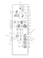
操作パネル30において、図5に示すように、飾りパネル31に設けられた複数の文字及び図形部分は、それぞれ操作部又は表示部として機能する。この飾りパネル31の切替表示領域40内に設けられた文字又は図形部分のうち、図6に示す操作部兼表示部50は、光源36と、透明電極フィルム34の検出部341とが重なって配置された複数の領域である。各操作部兼表示部50は、洗濯機10の運転に関する各種設定を行うための操作部と、この操作部による設定内容を表示する表示部である設定表示部とを兼用している。
Next, details of the operation unit and the display unit of the operation panel 30 will be described.
In the operation panel 30, as shown in FIG. 5, a plurality of characters and graphic parts provided on the decoration panel 31 function as an operation unit or a display unit, respectively. Of the character or graphic portion provided in the switching display area 40 of the decorative panel 31, the operation unit / display unit 50 shown in FIG. 6 is arranged so that the light source 36 and the detection unit 341 of the transparent electrode film 34 overlap each other. A plurality of regions. Each operation unit / display unit 50 also serves as an operation unit for performing various settings related to the operation of the washing machine 10 and a setting display unit which is a display unit for displaying the setting contents by the operation unit.
各操作部兼表示部50のうち主要なものについて説明する。各操作部兼表示部50のうちの一部は、設定内容や目的等に応じて複数の階層、この場合、図7に示すように、第一階層群51と第二階層群52と第三階層群53とに分類されている。第一階層群51が最上位の階層であり、第二階層群52、第三階層群53の順に下位の階層となる。操作部兼表示部50のうち、第一階層群51、第二階層群52、及び第三階層群53のいずれかに属する操作部兼表示部50は、それぞれ階層表示部として機能する。
The main ones of the operation unit / display unit 50 will be described. A part of each operation unit / display unit 50 has a plurality of hierarchies in accordance with setting contents, purposes, and the like. In this case, as shown in FIG. It is classified into a hierarchy group 53. The first hierarchy group 51 is the highest hierarchy, and the lower hierarchy is the second hierarchy group 52 and the third hierarchy group 53 in this order. Of the operation unit / display unit 50, the operation unit / display unit 50 belonging to any one of the first layer group 51, the second layer group 52, and the third layer group 53 functions as a layer display unit.
最上位の階層である第一階層群51は、運転内容を選択するためものである。第一階層群51は、例えば乾燥運転のみを行う「乾燥」ボタン511、洗濯及び乾燥運転を行う「洗乾」ボタン512、洗濯運転のみを行う「洗濯」ボタン513、そして、除菌・消臭運転を行う「除菌・消臭」ボタン514で構成されている。各ボタン511〜514は、それぞれ最上位の階層に属する第一階層表示部として機能する。
The first hierarchy group 51, which is the highest hierarchy, is for selecting operation details. The first hierarchy group 51 includes, for example, a “dry” button 511 that performs only a dry operation, a “wash and dry” button 512 that performs a wash and dry operation, a “wash” button 513 that performs only a wash operation, and sterilization / deodorization It comprises a “sterilization / deodorization” button 514 for driving. Each button 511 to 514 functions as a first layer display unit belonging to the highest layer.
上位から二番目の階層となる第二階層群52は、第一階層群51の操作により選択した運転内容の各行程について、その各行程の詳細内容を変更するためのものである。第二階層群52は、「洗い」ボタン521、「すすぎ」ボタン522、「脱水」ボタン523、「乾燥」ボタン524、及び「コース変更・個別メニュー」ボタン525で構成されている。「洗い」ボタン521、「すすぎ」ボタン522、「脱水」ボタン523、及び「乾燥」ボタン524は、各ボタン521〜524の名称に対応した行程の時間及び回数を、第一階層群51の操作により選択された運転内容の範囲内において、使用者の任意の内容に変更するためのものである。「コース変更・個別メニュー」ボタン525は、第一階層群51の操作により選択された運転内容の範囲内において、「洗い」、「すすぎ」、「脱水」、「乾燥」の各行程の組み合わせ及び時間を、後述する運転コースとしてメーカが推奨する内容に変更するためのものである。各ボタン521〜525は、それぞれ上位から二番目の階層に属する第二階層表示部として機能する。
The second hierarchy group 52, which is the second hierarchy from the top, is for changing the detailed content of each stroke for each stroke of the operation content selected by the operation of the first hierarchy group 51. The second hierarchy group 52 includes a “wash” button 521, a “rinse” button 522, a “dehydration” button 523, a “dry” button 524, and a “course change / individual menu” button 525. The “wash” button 521, the “rinse” button 522, the “dehydration” button 523, and the “dry” button 524 are used to set the process time and number of times corresponding to the names of the buttons 521 to 524 to the operation of the first layer group 51. In the range of the operation content selected by the above, the content is changed to any content of the user. “Course change / individual menu” button 525 includes combinations of “washing”, “rinsing”, “dehydration”, and “drying” processes within the range of the operation content selected by the operation of first layer group 51. This is for changing the time to a content recommended by the manufacturer as an operation course to be described later. Each button 521 to 525 functions as a second layer display unit belonging to the second layer from the top.
上位から三番目の階層である第三階層群53は、第三階層A群54、第三階層B群55、及び第三階層C群59により構成されている。第三階層A群54は、第一階層群51の「除菌・消臭」ボタン514が選択された場合、その除菌・消臭に関する行程についてメーカが推奨する具体的内容に変更するためのものである。第三階層A群54は、例えば「カビプロテクト」ボタン541、「ドラム静止」ボタン542、「ドラム回転」ボタン543から構成されている。例えば「カビプロテクト」ボタン541の操作により「カビプロテクト」が選択されると、洗濯運転の終了後に回転槽内へ除菌成分が供給され、カビの発生が抑制される。
The third layer group 53, which is the third layer from the top, includes a third layer A group 54, a third layer B group 55, and a third layer C group 59. When the “sterilization / deodorization” button 514 of the first hierarchy group 51 is selected, the third hierarchy A group 54 is used to change to the specific content recommended by the manufacturer for the process related to the sterilization / deodorization. Is. The third layer A group 54 includes, for example, a “mold protect” button 541, a “drum stationary” button 542, and a “drum rotation” button 543. For example, when “mold protection” is selected by operating the “mold protection” button 541, the disinfecting component is supplied into the rotating tub after the washing operation is completed, and the generation of mold is suppressed.
第三階層B群55は、第二階層群52の「コース変更・個別メニュー」ボタン525が選択された場合、運転コースの各行程についてメーカが推奨する具体的内容に変更するためのものである。第三階層B群55は、「標準」ボタン551、「メモリー」ボタン552、「ザブザブ」ボタン553、その他複数のボタン554〜561から構成されている。これら第三階層B群55を構成する各ボタン551〜561は、運転のコースに関する内容を表示するコース表示部として機能する。
The third level B group 55 is for changing to the specific content recommended by the manufacturer for each process of the driving course when the “course change / individual menu” button 525 of the second level group 52 is selected. . The third layer B group 55 includes a “standard” button 551, a “memory” button 552, a “subordinate” button 553, and a plurality of other buttons 554 to 561. Each button 551-561 which comprises these 3rd hierarchy B groups 55 functions as a course display part which displays the content regarding the driving | running course.
「標準」ボタン551は、運転コースの各行程についてメーカが推奨する標準的な内容に変更するものである。「メモリー」ボタン552は、使用者が記憶させた好みの内容に変更するものである。「ザブザブ」ボタン553は、「標準」よりも多めの水をためて、衣類をこすり洗いする内容に変更するものである。なお、各階層群51〜53の構成や、各ボタンの選択により行われる運転の具体的内容については、上述した構成に限られず、適宜変更することができる。
The “standard” button 551 is used to change the standard content recommended by the manufacturer for each process of the driving course. The “memory” button 552 is used to change the user's favorite content stored. The “zab zab” button 553 is used to change the content to rub the clothes with more water than “standard”. In addition, about the structure of each hierarchy group 51-53, and the specific content of the driving | operation performed by selection of each button, it is not restricted to the structure mentioned above, It can change suitably.
第三階層C群59は、追加設定の内容を選択するためのものである。追加設定とは、各種運転の内容に対して追加的に設定されるものである。追加設定は、使用者の任意で設定可能である。追加設定には、例えば、洗い水位の高低、すすぎ回数、節電に関する運転、又は除菌水を用いた運転等があるが、これらに限られない。この場合、第三階層C群59は、「水位」ボタン591、「ふろ水」ボタン592、及び「すすぎ回数」ボタン593等から構成されている。
The third layer C group 59 is for selecting the contents of additional setting. The additional setting is additionally set for the contents of various operations. Additional settings can be arbitrarily set by the user. Examples of the additional setting include, but are not limited to, the level of washing water, the number of times of rinsing, the operation related to power saving, or the operation using sterilized water. In this case, the third layer C group 59 includes a “water level” button 591, a “floating water” button 592, a “number of times of rinsing” button 593, and the like.
「水位」ボタン591は、第二階層群52の「洗い」ボタン524による洗い行程、及び「すすぎ」ボタン523によるすすぎ行程に関して、水位の高低を設定するためのものである。「ふろ水」592は、第二階層群52の「洗い」ボタン524による洗い行程、及び「すすぎ」ボタン523によるすすぎ行程に関して、ふろ水の利用の有無を設定するものである。「すすぎ回数」ボタン593は、第二階層群52の「すすぎ」ボタン523によるすすぎ行程に関して、すすぎ回数を設定するためのものである。各ボタン541〜543、551〜561、591〜593は、それぞれ上位から三番目の階層に属する第三階層表示部として機能する。
The “water level” button 591 is for setting the level of the water level for the washing process by the “washing” button 524 of the second layer group 52 and the rinsing process by the “rinsing” button 523. “Frozen water” 592 sets whether or not to use bath water for the washing process by the “washing” button 524 and the rinsing process by the “rinse” button 523 in the second layer group 52. The “number of times of rinsing” button 593 is for setting the number of times of rinsing with respect to the rinsing process by the “rinsing” button 523 of the second hierarchy group 52. Each of the buttons 541 to 543, 551 to 561, and 591 to 593 functions as a third layer display unit belonging to the third layer from the top.
各操作部兼表示部50のうち、各階層群51〜53に属する各ボタンは、各階層群51〜53ごとにその表示形態が揃えられている。具体的には、第一階層群51に属する各ボタン511〜514は、図5及び図6にも示すように、「乾燥」、「洗乾」など運転コースの内容を示す文字を円形の枠で囲った形態に構成されている。第二階層群52に属する各ボタン521〜524は、「洗い」、「すすぎ」など行程の内容を示す文字を正方形の枠で囲った形態に構成されている。この場合、第二階層群52の各ボタン521〜524の枠の一辺は、第一階層群51の各ボタン511〜514の直径と同じか又は小さい。そのため、第二階層群52の各ボタン521〜524は、使用者に、第一階層群51の各ボタン511〜514よりも小さい形状に認識され易い。
Among the operation unit / display unit 50, the buttons belonging to each of the hierarchical groups 51 to 53 have the same display form for each of the hierarchical groups 51 to 53. Specifically, each of the buttons 511 to 514 belonging to the first hierarchy group 51 has a circular frame indicating characters indicating the contents of the driving course such as “dry” and “wash dry” as shown in FIGS. It is comprised in the form enclosed by. The buttons 521 to 524 belonging to the second layer group 52 are configured in such a manner that characters indicating the contents of the process such as “wash” and “rinse” are surrounded by a square frame. In this case, one side of the frame of each button 521 to 524 of the second layer group 52 is the same as or smaller than the diameter of each button 511 to 514 of the first layer group 51. Therefore, the buttons 521 to 524 of the second layer group 52 are easily recognized by the user in a shape smaller than the buttons 511 to 514 of the first layer group 51.
第三階層群53に属する各ボタン541〜543、551〜561、591〜593は、「カビプロテクト」や「標準」などコース内容を示す文字を横長の矩形の枠で囲った形態に構成されている。この場合、第三階層群53の各ボタン541〜543、551〜561、591〜593の枠の短手方向の辺は、第二階層群52の各ボタン521〜524の一辺よりも小さい。そのため、第三階層群53の各ボタン541〜543、551〜561、591〜593は、使用者に、第二階層群52の各ボタン521〜524よりも小さい形状に認識され易い。
The buttons 541 to 543, 551 to 561, 591 to 593 belonging to the third layer group 53 are configured in a form in which characters indicating course contents such as “mold protection” and “standard” are surrounded by a horizontally long rectangular frame. Yes. In this case, the sides in the short direction of the frames of the buttons 541 to 543, 551 to 561, and 591 to 593 of the third layer group 53 are smaller than one side of the buttons 521 to 524 of the second layer group 52. Therefore, the buttons 541 to 543, 551 to 561, and 591 to 593 of the third layer group 53 are easily recognized by the user in a shape smaller than the buttons 521 to 524 of the second layer group 52.
また、操作パネル30は、いずれの階層51〜53にも属さない操作部兼表示部50として、図6に示すように、ダイヤル57及び「スタート・一時停止」ボタン58を備えている。ダイヤル57は、例えば分刻みの設定など、細かい設定をアップダウン操作する際に用いられる。「スタート・一時停止」ボタン58は、設定された内容での運転を開始する際や、運転中にその運転を一時停止させる際などに用いられる。この場合、「スタート・一時停止」ボタン58は、スタートボタン及び一時停止ボタンとして機能する。
Further, the operation panel 30 includes a dial 57 and a “start / pause” button 58 as an operation unit / display unit 50 that does not belong to any of the layers 51 to 53 as shown in FIG. The dial 57 is used for up / down operation of fine settings such as minute setting. The “start / pause” button 58 is used when starting the operation with the set contents, or when pausing the operation during the operation. In this case, the “start / pause” button 58 functions as a start button and a pause button.
ダイヤル57は、円形に構成された表示部571及び操作部572を有している。表示部571は、「スタート・一時停止」ボタン58を囲む円形に構成されている。操作パネル30の表示部571部分には、図8に示すように、表示部571の周方向に沿って複数この場合6個の光源36が設けられている。また、操作部572は、表示部571の外周側にあって円形に設けられている。この操作部572部分には、円形の図形の周方向に沿って複数の検出部341が設けられている。また、「スタート・一時停止」ボタン58の裏側には、光源36及び検出部341が設けられている。「スタート・一時停止」ボタン58に対応する光源36が点灯することにより、「スタート・一時停止」の文字が、飾りパネル31の表面に浮かび上がるように表示される。
The dial 57 has a display unit 571 and an operation unit 572 configured in a circular shape. The display unit 571 has a circular shape surrounding the “start / pause” button 58. In the display unit 571 portion of the operation panel 30, as shown in FIG. 8, a plurality of, in this case, six light sources 36 are provided along the circumferential direction of the display unit 571. The operation unit 572 is provided in a circular shape on the outer peripheral side of the display unit 571. The operation unit 572 is provided with a plurality of detection units 341 along the circumferential direction of the circular figure. Further, a light source 36 and a detection unit 341 are provided on the back side of the “start / pause” button 58. When the light source 36 corresponding to the “start / pause” button 58 is turned on, the characters “start / pause” are displayed so as to float on the surface of the decorative panel 31.
ダイヤル57において、図9の(a)〜(c)に示すように、使用者の指90がダイヤル57の操作部572に触れると、制御装置20は、検出部341の検出に基づいて、表示部571のうち指90が触れた部分に対応する光源36を点灯させる。これにより、表示部571のうち指90が触れた部分が表示される。なお、図9の(a)〜(c)では、表示部571のうち光源36の点灯により表示されている部分を黒く塗りつぶして示している。使用者がダイヤル57の操作部572を該操作部572の周方向へなぞると、ダイヤル57の周方向へ配置された各検出部341による検出位置が順次切り替わり、これにより、ダイヤル57に対する回転操作が検出される。制御装置20は、この回転操作に伴い光源36の点灯を切替える。これにより、使用者の指90の回転操作に追従するようにして、表示部571の点灯表示される部分が移動する。この場合、使用者の指90が触れている部分を高輝度で表示し、使用者の指90が触れていない部分を消灯させるか、または低輝度で表示させればよい。
When the user's finger 90 touches the operation unit 572 of the dial 57 on the dial 57 as shown in FIGS. 9A to 9C, the control device 20 displays based on the detection of the detection unit 341. The light source 36 corresponding to the part touched by the finger 90 in the part 571 is turned on. Thereby, the part which the finger | toe 90 touched among the display parts 571 is displayed. In FIGS. 9A to 9C, the portion of the display portion 571 that is displayed by turning on the light source 36 is shown in black. When the user traces the operation portion 572 of the dial 57 in the circumferential direction of the operation portion 572, the detection positions by the detection portions 341 arranged in the circumferential direction of the dial 57 are sequentially switched, and thereby the rotation operation on the dial 57 is performed. Detected. The control device 20 switches lighting of the light source 36 in accordance with this rotation operation. Accordingly, the portion of the display unit 571 that is lit and moved is moved so as to follow the rotation operation of the user's finger 90. In this case, the portion touched by the user's finger 90 may be displayed with high brightness, and the portion not touched with the user's finger 90 may be turned off or displayed with low brightness.
操作パネル30において、図10に示す文字部分は、表示部60として機能する。表示部60は、飾りパネル31の切替表示領域40内において、文字又は図形部分と、光源36とが重なって配置された複数の領域である。表示部60は、さらに操作部兼表示部50による設定内容を表示する設定表示部61と、洗濯機10の現在の状態に関する情報を表示する状態表示部63と、使用者に注意を促すための表示を行う注意表示部64と、補助的な内容を表示する補助表示部65と、に分類されている。
In the operation panel 30, the character portion shown in FIG. 10 functions as the display unit 60. The display unit 60 is a plurality of areas in which the character or graphic part and the light source 36 are overlapped in the switching display area 40 of the decoration panel 31. The display unit 60 further includes a setting display unit 61 that displays the setting content by the operation unit and display unit 50, a state display unit 63 that displays information on the current state of the washing machine 10, and a warning for the user. The display is classified into a caution display section 64 that performs display and an auxiliary display section 65 that displays auxiliary content.
各設定表示部61のうち、設定表示部611〜620は、それぞれ第二階層群52の各ボタン522〜514のいずれかに属しており、各ボタン522〜514が示す運転内容の詳細を表示する。例えば、各設定表示部61のうち、7セグメント表示の表示部611、「乾燥自動」表示部612、「お急ぎ」表示部613、「アイロン」表示部614、「除菌乾燥」表示部615、及び「上質乾燥」表示部616は、第二階層群52の「乾燥」ボタン524に属している。7セグメント表示の表示部617、及び「脱水自動」表示部618は、第二階層群52の「脱水」ボタン523に属している。また、7セグメント表示の表示部619は「すすぎ」ボタン522に属し、7セグメント表示の表示部620は「洗い」ボタン521に属している。
Among the setting display units 61, the setting display units 611 to 620 belong to any of the buttons 522 to 514 of the second hierarchy group 52, respectively, and display details of the operation contents indicated by the buttons 522 to 514. . For example, among the setting display units 61, a 7-segment display display unit 611, an “automatic drying” display unit 612, an “urgent” display unit 613, an “iron” display unit 614, a “sterilization drying” display unit 615, The “high quality dry” display unit 616 belongs to the “dry” button 524 of the second layer group 52. The display unit 617 for 7 segment display and the “automatic dehydration” display unit 618 belong to the “dehydration” button 523 of the second layer group 52. The display unit 619 for 7-segment display belongs to the “rinse” button 522, and the display unit 620 for 7-segment display belongs to the “wash” button 521.
各設定表示部61のうち、設定表示部621、622は、追加設定の内容を表示する追加設定表示部として機能する。追加設定表示部621は、第三階層C群59の「水位」ボタン591に属している。追加設定表示部621は、「水位」ボタン591がタッチ操作されることにより、「自動」、「低」、「中」、「高」の順に順次表示が切り替わる。追加設定表示部622は、第三階層C群59の「ふろ水」ボタン592に属している。追加設定表示部622は、「ふろ水」592がタッチ操作されることにより、「洗い」、「すすぎ1」、「すすぎ2」、「すすぎ3」の表示の組合せが順次切り替わる。
Among the setting display units 61, the setting display units 621 and 622 function as an additional setting display unit that displays the contents of the additional setting. The additional setting display unit 621 belongs to the “water level” button 591 of the third layer C group 59. When the “water level” button 591 is touched, the additional setting display unit 621 is switched in order of “automatic”, “low”, “medium”, and “high”. The additional setting display unit 622 belongs to the “floating water” button 592 of the third layer C group 59. The additional setting display unit 622 sequentially switches the combination of “wash”, “rinse 1”, “rinse 2”, and “rinse 3” when “bath water” 592 is touched.
状態表示部63は、7セグメントディスプレイ323などにより、現在時刻や、運転終了までの残り時間などを表示する。注意表示部64は、例えば「容量オーバー」表示部641、「槽内水あり」表示部642、「衣類片寄り」表示部643、及び「フィルターお掃除」表示部644などで構成されている。注意表示部64が表示されることで、使用者に対し洗濯機10に生じた異常を報知する。この場合、各操作部兼表示部50や、設定表示部61、及び状態表示部63は、白系の色で表示される。一方、注意表示部64は、例えば赤や橙など暖色系の色で表示される。これにより、注意表示部64は、その表示内容がより目立つように表示される。また、補助表示部65は、例えば「eco」や「Ag抗菌水」など、運転には直接影響の無い補助的な内容を表示するものである。この場合、補助表示部65のうち、「eco」や「Ag抗菌水」を例えば緑色等、各操作部兼表示部50や注意表示部64等の他の表示部と異なる色で表示させてもよい。
The status display unit 63 displays the current time, the remaining time until the end of operation, and the like on the 7-segment display 323 and the like. The attention display unit 64 includes, for example, an “over capacity” display unit 641, a “with water in tank” display unit 642, a “clothing offset” display unit 643, a “filter cleaning” display unit 644, and the like. By displaying the caution display unit 64, the user is notified of an abnormality that has occurred in the washing machine 10. In this case, the operation unit / display unit 50, the setting display unit 61, and the status display unit 63 are displayed in white color. On the other hand, the caution display unit 64 is displayed in a warm color such as red or orange. Thereby, the caution display part 64 is displayed so that the display content is more conspicuous. The auxiliary display unit 65 displays auxiliary contents that do not directly affect driving, such as “eco” and “Ag antibacterial water”. In this case, “eco” or “Ag antibacterial water” in the auxiliary display unit 65 may be displayed in a different color from other display units such as the operation unit / display unit 50 and the caution display unit 64 such as green. Good.
次に、操作パネル30による操作手順の詳細について図11〜図26も参照して説明する。光源36は、第一輝度、第二輝度、及び第三輝度の順に高輝度すなわち明るくなるよう三段階の輝度で発光可能に構成されている。つまり、光源36は、この三段階においては、第一輝度が最も暗く、第三輝度が最も明るい。また、操作パネル30の使用態様として、通常モードとデモモードとが選択可能に構成されている。通常モードは、洗濯機10が実際に使用される場合に設定されるモードであり、デモモードは、洗濯機10が店頭などにおいて展示される際に設定されるモードである。このデモモードでは、通常モードに比べて操作パネル30の文字及び図形部分が明るく表示される。
Next, details of the operation procedure by the operation panel 30 will be described with reference to FIGS. The light source 36 is configured to be able to emit light at three levels of brightness so as to increase in brightness in the order of the first brightness, the second brightness, and the third brightness. That is, the light source 36 has the darkest first brightness and the brightest third brightness in these three stages. Further, the usage mode of the operation panel 30 is configured so that a normal mode and a demo mode can be selected. The normal mode is a mode that is set when the washing machine 10 is actually used, and the demo mode is a mode that is set when the washing machine 10 is displayed at a store or the like. In this demonstration mode, characters and graphics on the operation panel 30 are displayed brighter than in the normal mode.
通常モードにおいて、表示部としての各操作部兼表示部50及び各表示部60は、第一輝度又は第二輝度の二種類の態様で表示される。すなわち、制御装置20は、各操作部兼表示部50及び各表示部60について、現在選択されていないが選択可能である設定内容を示すものを第一輝度で表示させ、現在選択されている設定内容を示すものを第二輝度で表示させる。これにより、制御装置20は、各操作部兼表示部50及び各表示部60について、現在選択されていないが選択可能である設定内容を示す第一表示と、現在選択されている設定内容を示す第二表示と、を区別して表示する。
In the normal mode, each operation unit / display unit 50 and each display unit 60 as a display unit are displayed in two types of modes of first luminance or second luminance. That is, the control device 20 displays, for each operation unit / display unit 50 and each display unit 60, a setting content that is not currently selected but is selectable and is displayed with the first luminance, and the currently selected setting. A content display is displayed at the second luminance. As a result, the control device 20 indicates the first display indicating the setting contents that are not currently selected but can be selected, and the setting contents that are currently selected, for each operation unit and display unit 50 and each display unit 60. The display is distinguished from the second display.
具体的には、制御装置20は、電源が投入されると、操作パネル30に対して、準備表示、初期表示、通常表示の順に表示を切り替えていく。そして、制御装置20は、使用者が運転内容を設定する際、使用者が第一階層群51、第二階層群52、第三階層群53の順に操作を行うよう使用者を誘導する。この誘導は、各操作の段階において、適宜、必要な操作部兼表示部50及び表示部60が表示させることで行われる。つまり、まず、洗濯機10の電源が入っていない状態においては、図11に示すように、飾りパネル31の表面には、電源入ボタン311及び電源切ボタン312だけが見えており、切替表示領域40内には何も表示されていない。
Specifically, when the power is turned on, the control device 20 switches the display on the operation panel 30 in the order of preparation display, initial display, and normal display. And the control apparatus 20 guides a user so that a user may operate in order of the 1st hierarchy group 51, the 2nd hierarchy group 52, and the 3rd hierarchy group 53, when a user sets the content of driving | operation. This guidance is performed by causing the necessary operation unit and display unit 50 and the display unit 60 to display appropriately in each operation stage. That is, first, when the washing machine 10 is not turned on, only the power on button 311 and the power off button 312 are visible on the surface of the decorative panel 31, as shown in FIG. Nothing is displayed in 40.
使用者が電源入ボタン311を操作すると、洗濯機10の電源が入る。すると、制御装置20は、図12に示すように、準備表示として、最上位の階層である第一階層群51に属するボタン511〜514のうち現在選択されている設定内容に対応する階層表示部を第一輝度で表示させるとともに、ダイヤル57の表示部571及び「スタート・一時停止」ボタン58を第一輝度で表示させる。本実施形態において、電源の投入直後は、洗乾運転が選択されているため、「洗乾」ボタン512、ダイヤル57の表示部571、及び「スタート・一時停止」ボタン58が第一輝度で表示される。このとき、周囲の湿度環境等に合わせるために各検出部341の検出値の補正すなわちキャリブレーションが行われる。また、このとき、検出部341によるタッチ操作の検出は行われない。
When the user operates the power on button 311, the washing machine 10 is powered on. Then, as illustrated in FIG. 12, the control device 20 displays, as a preparation display, a hierarchy display unit corresponding to the currently selected setting content among the buttons 511 to 514 belonging to the first hierarchy group 51 that is the highest hierarchy. Is displayed with the first luminance, and the display portion 571 of the dial 57 and the “start / pause” button 58 are displayed with the first luminance. In this embodiment, since the washing / drying operation is selected immediately after the power is turned on, the “wash / dry” button 512, the display unit 571 of the dial 57, and the “start / pause” button 58 are displayed with the first luminance. Is done. At this time, correction of the detection value of each detection unit 341, that is, calibration is performed in order to match the surrounding humidity environment and the like. At this time, the detection unit 341 does not detect the touch operation.
制御装置20は、準備表示を表示し、キャリブレーションを行った後、全ての検出部341によるタッチ操作の検出を開始する。制御装置20は、準備表示において、所定の条件が成立すると、準備表示に対し輝度を上げて初期表示を表示する。この場合、制御装置20は、例えば電源が投入されてから所定の時間が経過した場合、又は図13に示すように操作部兼表示部50のいずれかについて使用者の手指90によりタッチ操作が行われた場合に、初期表示を表示させる条件が成立したと判断して初期表示を行う。なお、制御装置20は、電源投入後、準備表示として表示を一切行わず、表示部を非表示のままキャリブレーションを実行し、その後、上述の所定の条件が成立した場合に、初期表示を表示する構成としてもよい。
After displaying the preparation display and performing calibration, the control device 20 starts detecting touch operations by all the detection units 341. When a predetermined condition is satisfied in the preparation display, the control device 20 increases the brightness with respect to the preparation display and displays an initial display. In this case, the control device 20 performs a touch operation with the user's finger 90 on either the operation unit / display unit 50, for example, when a predetermined time elapses after the power is turned on or as shown in FIG. If it is determined that the condition for displaying the initial display is satisfied, the initial display is performed. The control device 20 does not display as a preparation display after turning on the power, performs calibration without displaying the display unit, and then displays an initial display when the above-described predetermined condition is satisfied. It is good also as composition to do.
初期表示の内容は、製品の製造段階で予め定められた運転内容に基づいている。この場合、制御装置20は、初期表示において、少なくとも最上位の階層に属する階層表示部のうち現在選択されている設定内容に対応する階層表示部及び「スタート・一時停止」ボタン58を表示させる。この場合、制御装置20は、図14に示すように、最上位の階層である第一階層群51に属する階層表示部のうち現在選択されている設定内容に対応する洗乾ボタン512、ダイヤル57の表示部571、及び「スタート・一時停止」ボタン58を第二輝度で表示させる。
The content of the initial display is based on the operation content predetermined in the product manufacturing stage. In this case, in the initial display, the control device 20 displays at least the hierarchy display section corresponding to the currently selected setting contents and the “start / pause” button 58 among the hierarchy display sections belonging to the highest hierarchy. In this case, as shown in FIG. 14, the control device 20 includes the washing / drying button 512 and the dial 57 corresponding to the currently selected setting contents in the hierarchy display section belonging to the first hierarchy group 51 which is the highest hierarchy. The display unit 571 and the “start / pause” button 58 are displayed with the second luminance.
また、制御装置20は、最上位の階層以外の階層である第三階層B群55のうち、現在選択されている洗乾運転に関するコースの内容を示す「標準」ボタン551を第二輝度で表示させる。さらに、制御装置20は、最上位の階層である第一階層群51に属する階層表示部のうち現在選択されていないが操作可能となっている階層表示部、この場合、乾燥ボタン511、洗濯ボタン513、及び除菌・消臭ボタン514を、乾燥ボタン512よりも低輝度である第一輝度で表示させる。
In addition, the control device 20 displays the “standard” button 551 indicating the content of the course relating to the currently selected washing / drying operation in the second brightness in the third hierarchy B group 55 which is a hierarchy other than the highest hierarchy. Let Further, the control device 20 is a hierarchical display unit that is not currently selected but is operable among the hierarchical display units belonging to the first hierarchical group 51 that is the highest hierarchical level. In this case, the drying button 511, the washing button 513 and the sterilization / deodorizing button 514 are displayed with the first luminance which is lower than that of the dry button 512.
このように、飾りパネル31には、現在選択されていないが選択可能である設定内容を示す第一表示と、現在選択されている設定内容を示す第二表示と、が区別して表示される。すなわち、飾りパネル31には、現在選択中の設定と、選択候補とが区別して表示される。この場合、制御装置20は、初期表示において、最上位の階層である第一階層群51に属するボタン511〜514、ダイヤル57の表示部571、及び「スタート・一時停止」ボタン58以外の表示部については表示しない。
As described above, the decoration panel 31 displays the first display showing the setting contents that are not currently selected but can be selected, and the second display showing the currently selected setting contents. That is, the currently selected setting and the selection candidate are displayed on the decoration panel 31 separately. In this case, in the initial display, the control device 20 displays the display units other than the buttons 511 to 514 belonging to the first layer group 51 which is the highest layer, the display unit 571 of the dial 57, and the “start / pause” button 58. Is not displayed.
図14に示す初期表示が表示されている場合、制御装置20は、運転を開始するための準備が既に完了している。この初期表示において、制御装置20は、初期表示を表示させてから最初に「スタート・一時停止」ボタン58がタッチ操作されたことを検出すると、現在表示している運転内容、この場合、洗乾運転をそのまま開始する。一方、制御装置20は、図15に示すように、初期表示が表示されてから最初に「スタート・一時停止」ボタン58以外のボタンがタッチ操作されたことを検出すると、設定内容を変更するため、図16に示す通常表示を表示させる。通常表示において、制御装置20は、第一階層群51や、現在選択されている運転に関するコース表示部、この場合「標準」ボタン551以外の表示部についても表示させて、現在選択されている運転内容の詳細や、現在選択可能となっている運転内容に関する表示部を表示させる。これにより、使用者は、現在設定されている設定内容の詳細を確認でき、また、設定内容の変更が可能となる。
When the initial display shown in FIG. 14 is displayed, the control device 20 has already completed preparations for starting operation. In this initial display, when the control device 20 first detects that the “start / pause” button 58 has been touched after displaying the initial display, the operation content currently displayed, in this case, washing and drying. Start driving as it is. On the other hand, as shown in FIG. 15, when the control device 20 detects that a button other than the “start / pause” button 58 is first touched after the initial display is displayed, the control device 20 changes the setting content. The normal display shown in FIG. 16 is displayed. In the normal display, the control device 20 also displays the first hierarchy group 51 and the course display section related to the currently selected operation, in this case, the display section other than the “standard” button 551, and the currently selected operation. The display section regarding the details of the contents and the currently selected operation contents is displayed. As a result, the user can confirm the details of the currently set contents and can change the set contents.
通常表示が表示されている際、第二階層群52に対する操作において、図17に示すように使用者の指90によって「コース変更・個別メニュー」ボタン525がタッチ操作されると、制御装置20は、図18に示すように、選択された第二階層群52の「コース変更・個別メニュー」ボタン525に属する第三階層B群55のうち選択可能なボタン、この場合現在選択されている「標準」ボタン551を第二表示として第二輝度で表示し、それ以外の「メモリー」ボタン552、「ザブザブ」ボタン553、及びその他のボタン554〜558を第一表示として第一輝度で表示させる。その後、使用者が、例えば図19に示すように、「ザブザブ」ボタン553をタッチ操作して選択すると、制御装置20は「ザブザブ」コースを確定し、図20に示すように、「ザブザブ」ボタン553を第二表示とするため第二輝度に変更表示するとともに「標準」ボタン551、「メモリー」ボタン552などの他の候補の表示を第一表示とするため第一輝度にて表示する。
When the normal display is displayed, when the “course change / individual menu” button 525 is touch-operated by the user's finger 90 as shown in FIG. 18, a selectable button among the third layer B group 55 belonging to the “course change / individual menu” button 525 of the selected second layer group 52, in this case, the currently selected “standard” "Button 551 is displayed at the second luminance as the second display, and the other" memory "button 552," sub-zab "button 553, and the other buttons 554 to 558 are displayed at the first luminance as the first display. After that, when the user touches and selects the “Zab Zab” button 553 as shown in FIG. 19, for example, the control device 20 determines the “Zab Zab” course, and as shown in FIG. 20, the “Zab Zab” button The display is changed to the second luminance so that 553 is the second display, and other candidates such as the “standard” button 551 and the “memory” button 552 are displayed at the first luminance so as to be the first display.
その後、使用者は、選択した「ザブザブ」コースにおいて、さらに詳細な設定をするため、図21に示すように、第二階層群52のうち「乾燥」ボタン524をタッチ操作する。すると、図22に示すように、制御装置20は、設定表示部61のうち「ザブザブ」コースの「乾燥」運転において選択可能な表示部、この場合「乾燥自動」表示部612、「アイロン」表示部614、「除菌乾燥」表示部615、「上質乾燥」表示部616を表示させる。ここで、制御装置20は、まず「乾燥」ボタン524を操作した時点で選択されていた「乾燥自動」表示部612を第二表示として第二輝度で表示させる。一方、制御装置20は、「乾燥」ボタン524を操作した時点では選択されていなかった「アイロン」表示部614、「除菌乾燥」表示部615、「上質乾燥」表示部616については、第一表示として第一輝度で表示させる。
Thereafter, the user performs a touch operation on the “Dry” button 524 in the second layer group 52 as shown in FIG. 21 in order to make more detailed settings in the selected “Zab-Zab” course. Then, as shown in FIG. 22, the control device 20 can select a display unit that can be selected in the “dry” operation of the “Zab Zab” course in the setting display unit 61, in this case, an “automatic drying” display unit 612, an “iron” display Display unit 614, “sterilization drying” display unit 615, and “quality drying” display unit 616. Here, the control device 20 first displays the “automatic drying” display unit 612 selected at the time of operating the “drying” button 524 as the second display with the second luminance. On the other hand, the control device 20 does not select the “iron” display unit 614, the “sterilization dry” display unit 615, and the “quality dry” display unit 616 that were not selected at the time of operating the “dry” button 524. The display is made with the first luminance.
その後、使用者が、「乾燥」ボタン524を複数回繰り返してタッチ操作すると、図23、図24、図25に示すように、現在選択されている運転内容の詳細が順次切り替わり、その切り替わりに伴って第二表示として第二輝度で表示される表示部614、615、616も切り替わる。その後、例えば図26に示すように「上質乾燥」表示部616が第二表示として第二輝度で表示されそれ以外の選択されていない表示部が第一表示として第一輝度にて表示されている状態で、使用者が「スタート・一時停止」ボタン58をタッチ操作すると、制御装置20は、運転内容を全て確定する。そして、制御装置20は、図27に示すように、操作パネル30全体において第二輝度で表示される表示部のみを残して他は消灯するとともに、設定された洗乾運転を開始する。
Thereafter, when the user repeatedly touches the “dry” button 524 a plurality of times, as shown in FIGS. 23, 24, and 25, the details of the currently selected operation contents are sequentially switched. Then, the display units 614, 615, and 616 displayed at the second luminance as the second display are also switched. Thereafter, for example, as shown in FIG. 26, the “quality dry” display unit 616 is displayed as the second display at the second luminance, and the other non-selected display units are displayed as the first display at the first luminance. When the user touches the “start / pause” button 58 in the state, the control device 20 determines all the operation details. Then, as shown in FIG. 27, the control device 20 turns off the rest of the entire operation panel 30 except for the display portion displayed at the second luminance, and starts the set washing / drying operation.
洗濯機10の運転中は、図27に示すように「コース変更・個別メニュー」ボタン525が非表示となるため、運転内容の設定変更は不可となっている。一方、洗濯機10の運転中に使用者が「スタート・一時停止」ボタン58をタッチ操作すると、運転が一時停止される。そして、図26に示すように「コース変更・個別メニュー」ボタン525が第二表示として第二輝度で表示され、これにより運転内容の設定変更が可能となる。
While the washing machine 10 is in operation, the “change course / individual menu” button 525 is not displayed as shown in FIG. On the other hand, when the user touches the “start / pause” button 58 while the washing machine 10 is in operation, the operation is temporarily stopped. Then, as shown in FIG. 26, a “course change / individual menu” button 525 is displayed as the second display with the second luminance, and the setting of the operation content can be changed.
制御装置20は、運転開始後、使用者に操作されない状態が所定期間継続すると、操作パネル30を待機状態にする。制御装置20は、この待機状態において、光源36を消灯させて操作部兼表示部50及び表示部60を非表示にする。これにより、使用者が操作をする可能性が低い場合において、操作パネル30の待機電力を低減することができる。
この待機状態において、制御装置20は、検出部341を用いて使用者の接近を検出している。そして、制御装置20は、待機状態において使用者の接近を検出した場合には、検出・表示回路321を動作させて光源36を再び点灯させ、これにより必要な表示を行い、操作パネル30を操作可能な状態にする。
The control device 20 places the operation panel 30 in a standby state when a state in which the user does not operate continues for a predetermined period after the operation is started. In this standby state, the control device 20 turns off the light source 36 and hides the operation unit / display unit 50 and the display unit 60. Thereby, when the possibility that the user operates is low, the standby power of the operation panel 30 can be reduced.
In this standby state, the control device 20 detects the approach of the user using the detection unit 341. When the control device 20 detects the approach of the user in the standby state, it operates the detection / display circuit 321 to turn on the light source 36 again, thereby performing the necessary display and operating the operation panel 30. Make it possible.
すなわち、操作パネル30が待機状態でなく通常使用される状態においては、制御装置20は、複数の検出部341に対する個々のタッチ操作を検出する。一方、操作パネル30が待機状態となっている状態では、制御装置20は、複数の検出部341全体を一つのセンサとみなし、複数の検出部341の静電容量の変化を平均化して検出する。これにより、検出部341の検出感度が向上し、制御装置20は、操作パネル30からある程度離れた位置における使用者の存在を検出することができる。この場合、使用者が操作パネル30に接近したり手をかざしたりすることで、制御装置20が使用者の存在を検出する。そして、制御装置20は、使用者の接近を検出すると、操作パネル30の待機状態を解除し、操作パネル30への通常の操作を可能にする。
That is, when the operation panel 30 is not in a standby state and is normally used, the control device 20 detects individual touch operations on the plurality of detection units 341. On the other hand, when the operation panel 30 is in the standby state, the control device 20 regards the plurality of detection units 341 as a single sensor and averages and detects the change in capacitance of the plurality of detection units 341. . Thereby, the detection sensitivity of the detection unit 341 is improved, and the control device 20 can detect the presence of the user at a position away from the operation panel 30 to some extent. In this case, when the user approaches the operation panel 30 or holds his hand, the control device 20 detects the presence of the user. Then, when detecting the approach of the user, the control device 20 cancels the standby state of the operation panel 30 and enables normal operation on the operation panel 30.
また、洗濯機10は、インターネットや、パソコン、冷蔵庫、エアコン、テレビなど他の家電機器と通信可能に接続されてホームネットワークの構築が可能な構成であってもよい。この場合、ダイヤル57の表示部571を、そのネットワークの接続状態を表示するものとして用いることもできる。例えば、洗濯機10がネットワークに未接続の場合には、表示部571の表示を非表示にする。また、洗濯機10がネットワークへの接続を試みている場合には、上述のように表示部571の点灯表示される部分を周方向へ回転移動するように表示させる。そして、洗濯機10のネットワークへの接続が確立された場合には、表示部571全体を表示させる。
In addition, the washing machine 10 may be configured to be communicably connected to other home appliances such as the Internet, a personal computer, a refrigerator, an air conditioner, and a television to construct a home network. In this case, the display unit 571 of the dial 57 can be used to display the connection state of the network. For example, when the washing machine 10 is not connected to the network, the display on the display unit 571 is not displayed. In addition, when the washing machine 10 is trying to connect to the network, the portion of the display unit 571 that is lit and displayed is displayed so as to rotate and move in the circumferential direction as described above. When the connection of the washing machine 10 to the network is established, the entire display unit 571 is displayed.
さらに、表示部571の色調の変化や点滅を組み合わせることにより、洗濯機10のネットワークの接続状態を表示してもよい。例えば洗濯機10がネットワークに未接続の場合には表示部571を赤色で表示させ、ネットワークへの接続を試みている場合には表示部571を緑色で点滅させ、ネットワークへの接続が確立された場合には表示部571を緑色で表示させてもよい。
次に、デモモードについて説明する。このデモモードにおいては、表示部としての各操作部兼表示部50及び各表示部60は、第二輝度又は第三輝度の二種類の態様で表示される。すなわち、制御装置20は、各操作部兼表示部50及び各表示部60について、現在選択されていないが選択可能である設定内容を示すものを第二輝度で表示させ、現在選択されている設定内容を示すものを第三輝度で表示させる。そのため、デモモードでは、通常モードに比べて、各操作部兼表示部50及び各表示部60の表示が明るい。
Further, the network connection state of the washing machine 10 may be displayed by combining the change in color tone or blinking of the display unit 571. For example, when the washing machine 10 is not connected to the network, the display unit 571 is displayed in red, and when trying to connect to the network, the display unit 571 flashes in green, and the connection to the network is established. In that case, the display unit 571 may be displayed in green.
Next, the demo mode will be described. In this demonstration mode, each operation unit and display unit 50 and each display unit 60 as a display unit are displayed in two types of modes of second luminance or third luminance. That is, the control device 20 displays, for each operation unit / display unit 50 and each display unit 60, a setting content that is not currently selected but that can be selected is displayed with the second luminance, and is currently selected. The content is displayed with the third brightness. Therefore, in the demonstration mode, the display of each operation unit and display unit 50 and each display unit 60 is brighter than in the normal mode.
これによれば、運転の開始が可能となった初期表示においては、現在選択されている運転内容を表示する表示部のうち最上位の階層に属する表示部であって現在選択されている表示部及び「スタート・一時停止」ボタン58が表示される。この場合、使用者の視覚に入る表示が少ないため、使用者に対して煩雑な感じを起こさせ難く、したがって、操作パネル30の初期表示を意匠性の高いものとすることができる。また、初期表示において、使用者の視覚に入る情報量が少ないため、使用者は、現在どの運転内容が選択されているか一目で判断することができる。そして、表示されている操作可能なボタンの数が少ないため、使用者は、「スタート・一時停止」ボタン58を一見して認識することができる。これらの結果、操作パネル30は、直観的な操作が可能となり操作性の向上が図られる。
According to this, in the initial display in which the operation can be started, the display unit that belongs to the highest hierarchy among the display units that display the operation content that is currently selected, and the display unit that is currently selected And a “start / pause” button 58 is displayed. In this case, since there are few displays that can be seen by the user, it is difficult for the user to feel complicated, and thus the initial display of the operation panel 30 can be highly designed. Also, since the amount of information that can be seen by the user in the initial display is small, the user can determine at a glance which driving content is currently selected. Since the number of operable buttons displayed is small, the user can recognize the “start / pause” button 58 at a glance. As a result, the operation panel 30 can be operated intuitively and operability is improved.
制御装置20は、初期表示において、運転のコースに関する内容を表示する複数のコース表示部551〜561のうち、現在選択されている運転に関する内容を示すコース表示部を表示させる。すなわち、洗乾運転で標準コースが選択されている場合、制御装置20は、初期表示において、第三階層B群55に属する複数のボタン551〜561のうち、現在選択されているコース内容を示す「標準」ボタン551を表示させる。これによれば、使用者は、煩雑な印象を受けることなく、運転コースの内容を一見して把握することができる。このように、操作パネル30に運転開始に必要な最小限の表示をさせることで、意匠性の向上を図りつつ直感的な操作が可能となり、操作性のさらなる向上が図られる。
In the initial display, the control device 20 displays a course display unit that indicates the content related to the currently selected driving among the plurality of course display units 551 to 561 that display the content related to the driving course. That is, when the standard course is selected in the washing / drying operation, the control device 20 shows the content of the currently selected course among the plurality of buttons 551 to 561 belonging to the third layer B group 55 in the initial display. A “standard” button 551 is displayed. According to this, the user can grasp the contents of the driving course at a glance without receiving a complicated impression. In this way, by causing the operation panel 30 to display the minimum display necessary for starting operation, an intuitive operation can be performed while improving the design, and the operability can be further improved.
また、制御装置20は、操作パネル30の操作が可能となっている初期表示又は通常表示において、操作パネル30の操作部兼表示部50及び表示部60について、現在選択されていないが選択可能である設定内容を示す第一表示と、現在選択されている設定内容を示す第二表示とを区別して表示する。したがって、使用者は、操作パネル30のうち、現在どの様な設定がされており、また、現在どのボタンが操作可能であるかを一見して判断することができるため、直観的な操作が可能となる。
この場合、制御装置20は、第二表示を第一表示に比べて高輝度で表示する。そのため、使用者は、操作パネル30のうち、現在どの様な設定がされており、また、現在どのボタンが操作可能であるかをより明確に区別して判断することができる。
The control device 20 can select the operation unit / display unit 50 and the display unit 60 of the operation panel 30 that are not currently selected in the initial display or the normal display in which the operation panel 30 can be operated. A first display showing a certain setting content and a second display showing the currently selected setting content are displayed separately. Therefore, since the user can determine at a glance which setting is currently set on the operation panel 30 and which button is operable, an intuitive operation is possible. It becomes.
In this case, the control device 20 displays the second display with higher brightness than the first display. Therefore, the user can more clearly distinguish and determine what setting is currently made on the operation panel 30 and which button is currently operable.
また、表示部としての各操作部兼表示部50のうち運転の設定の変更に主に用いられるボタンについては、その設定内容に応じて複数の階層、この場合、第一階層群51、第二階層群52、及び第三階層群53の三階層に分類されている。そして、各階層群51〜53に属する各ボタンは、その表示形態が各階層群51〜53ごとに揃えられている。そして、各階層群51〜53に属する各ボタンは、操作順となる第一階層群51、第二階層群52、第三階層群53の順に次第にその形状が小さくなるよう構成されている。このため、使用者は、運転に関する設定を行う際、大きいボタンから小さいボタンへ順次操作していけばよいため、より直観的な操作が可能になる。
Moreover, about the button mainly used for the change of driving | running | working setting among each operation part and display part 50 as a display part, according to the setting content, in several layers, in this case, 1st hierarchy group 51, 2nd They are classified into three layers, a layer group 52 and a third layer group 53. And each button which belongs to each hierarchy group 51-53 has the display form arranged for every hierarchy group 51-53. And each button which belongs to each hierarchy group 51-53 is comprised so that the shape may become small gradually in order of the 1st hierarchy group 51 which becomes operation order, the 2nd hierarchy group 52, and the 3rd hierarchy group 53. For this reason, when the user performs settings related to driving, it is only necessary to sequentially operate from a large button to a small button, and thus a more intuitive operation is possible.
一般に、静電容量式の検出部341は、周囲の湿度環境等に合わせるため、洗濯機10に電源が投入される度に各検出部341のキャリブレーションを行う。このキャリブレーションを行っている最中は、制御装置20は、電源が投入されているにもかかわらず操作パネル30に対するタッチ操作を検出することができない。そこで、制御装置20は、洗濯機10に電源が投入された直後、操作パネル30について、準備表示として第一輝度で所定の表示部を表示させた後、検出部341による使用者のタッチ操作の検出を可能な状態にする。そして、制御装置20は、準備表示を表示させている間に、検出部341のキャリブレーションを行う。
In general, the capacitance type detection unit 341 calibrates each detection unit 341 every time the washing machine 10 is powered on in order to match the surrounding humidity environment and the like. During the calibration, the control device 20 cannot detect a touch operation on the operation panel 30 even though the power is turned on. Therefore, immediately after the washing machine 10 is turned on, the control device 20 causes the operation panel 30 to display a predetermined display unit with the first luminance as a preparation display, and then performs a user's touch operation by the detection unit 341. Make detection possible. Then, the control device 20 calibrates the detection unit 341 while displaying the preparation display.
これによれば、準備表示として第一輝度で表示された状態は通常の使用状態と明らかに異なるため、使用者に対し電源が投入されたにもかかわらず操作パネル30の操作ができないという違和感を与えることなく、検出部341のキャリブレーションを行うことができる。
制御装置20は、初期表示を表示している最中に操作部兼表示部50に対するタッチ操作を検出した場合、通常表示として現在選択されている設定内容に対応する操作部兼表示部50について最上位以外の階層に属する階層表示部52、53も表示させる。これによれば、使用者が現在設定されている内容を確認したい場合等に、現在選択されている設定内容の詳細を容易に確認することができる。
According to this, since the state displayed with the first luminance as the preparation display is clearly different from the normal use state, the user feels uncomfortable that the operation panel 30 cannot be operated even when the power is turned on. The calibration of the detection unit 341 can be performed without giving.
When the control device 20 detects a touch operation on the operation unit / display unit 50 while the initial display is being displayed, the control device 20 selects the operation unit / display unit 50 corresponding to the setting content currently selected as the normal display. Hierarchy display units 52 and 53 belonging to layers other than the upper layer are also displayed. According to this, when the user wants to confirm the currently set content, the details of the currently selected set content can be easily confirmed.
制御装置20は、電源投入後であって初期表示を表示するまでの間における準備表示として、表示部及び「スタート・一時停止」ボタン58を、非表示又は初期表示に対して輝度を下げて表示させる。これによれば、使用者は、準備表示が表示されている間は操作パネルの操作ができないことを一見して認識することができる。したがって、操作パネル30の操作性の向上が図られる。
また、制御装置20は、使用者に操作されない状態が所定期間継続すると、光源36を消灯させて操作パネル30を待機状態にする。そして、制御装置20は、待機状態において、使用者の接近を検出した場合には、検出・表示回路321を動作させて光源36を再び点灯させることで必要な表示を行い、操作パネル30を操作可能な状態にする。これによれば、操作パネル30の消費電力を低減することができる。
The control device 20 displays the display unit and the “start / pause” button 58 as a preparatory display after the power is turned on until the initial display is displayed, with non-display or lower brightness than the initial display. Let According to this, the user can recognize at a glance that the operation panel cannot be operated while the preparation display is displayed. Therefore, the operability of the operation panel 30 can be improved.
In addition, when the state that is not operated by the user continues for a predetermined period, the control device 20 turns off the light source 36 and puts the operation panel 30 in a standby state. When the control device 20 detects the approach of the user in the standby state, the control device 20 operates the detection / display circuit 321 to turn on the light source 36 again to perform a necessary display, and operates the operation panel 30. Make it possible. According to this, the power consumption of the operation panel 30 can be reduced.
そして、制御装置20は、操作パネル30に対する操作を検出するための検出部341を用いて使用者の接近を検出する。これによれば、使用者の接近を検出するための、別途個別にセンサ等を設ける必要がない。
また、洗濯機10は、操作パネル30について、当該洗濯機10が実際に使用される場合に設定される通常モードに加え、当該洗濯機10が販売店の店頭などにおいて展示される際に設定されるデモモードを備えている。販売店では実際に洗濯機が使用される一般家庭に比べて商品がより良く見える様に周囲が明るい照明となっているため、デモモードは表示部50、60を通常モードよりも高輝度で表示させるようになっている。これによれば、例えば洗濯機10が店頭で展示される際に周囲が明るい環境であっても、操作パネル30の表示部50、60をはっきりと表示させることができる。
And the control apparatus 20 detects a user's approach using the detection part 341 for detecting operation with respect to the operation panel 30. FIG. According to this, it is not necessary to separately provide a sensor or the like for detecting the approach of the user.
The washing machine 10 is set for the operation panel 30 when the washing machine 10 is displayed at a store or the like in addition to the normal mode set when the washing machine 10 is actually used. It has a demo mode. In the store, the lighting is bright so that the product can be seen better than in a general household where the washing machine is actually used, so the demo mode displays the display units 50 and 60 with higher brightness than the normal mode. It is supposed to let you. According to this, for example, even when the washing machine 10 is displayed at a storefront, the display units 50 and 60 of the operation panel 30 can be clearly displayed even in a bright environment.
そして、各操作部兼表示部50や、設定表示部61、及び状態表示部63は、白系の色で表示される一方、注意表示部64は、例えば赤や橙など暖色系の色で表示される。これによれば、注意表示部64について、その表示内容をより目立たせることができ、その結果、より効果的に使用者の注意を引くことができる。
The operation unit / display unit 50, the setting display unit 61, and the status display unit 63 are displayed in a white color, while the caution display unit 64 is displayed in a warm color such as red or orange. The According to this, the display content of the caution display unit 64 can be made more conspicuous, and as a result, the user's attention can be drawn more effectively.
(第二実施形態)
以下、第二実施形態による洗濯機について、図30を参照して説明する。なお、洗濯機の構成は、第一実施形態とほぼ共通するので、図1〜図29をも参照しつつ、その詳細な説明は省略する。
本実施形態では、洗濯機10の操作パネル30(図1参照)は、その表面側に飾りパネル31が設けられている。この飾りパネル31は、第一実施形態にて説明したように、全体として遮光性を有する一方、設定用の文字等に対応する部位に透光性を有している。この飾りパネル31は、その表面、すなわち、飾りパネル31の表面が、洗濯機本体11と同系統の白色系の塗料で塗装されている。また、操作パネル30の表面は、凹凸が無いほぼ平坦な形状(ただし洗濯機10の上部側の形状に合わせた曲面状)に形成されている。
(Second embodiment)
Hereinafter, the washing machine according to the second embodiment will be described with reference to FIG. In addition, since the structure of a washing machine is substantially the same as 1st embodiment, the detailed description is abbreviate | omitted also referring FIGS.
In the present embodiment, the operation panel 30 (see FIG. 1) of the washing machine 10 is provided with a decorative panel 31 on the surface side. As described in the first embodiment, the decorative panel 31 has a light shielding property as a whole, and has a light transmitting property at a portion corresponding to a setting character or the like. The surface of the decorative panel 31, that is, the surface of the decorative panel 31 is painted with the same white paint as that of the washing machine body 11. Further, the surface of the operation panel 30 is formed in a substantially flat shape with no irregularities (however, a curved shape matching the shape of the upper side of the washing machine 10).
飾りパネルの背面側には、光源36(図4参照。白色光源に相当する)が設けられている。この光源は、白色LEDで構成されており、白色系の光を照射する。つまり、本実施形態の洗濯機10は、白色系の操作パネル30に白色系の文字で設定項目等を表示する操作部兼表示部50(図6参照。白色表示部に相当する)を備えている。なお、飾りパネル31は、その表面に例えばヘアーライン等の意匠を施したものであってもよい。
A light source 36 (see FIG. 4, corresponding to a white light source) is provided on the back side of the decorative panel. This light source is composed of a white LED and emits white light. That is, the washing machine 10 of the present embodiment includes an operation unit / display unit 50 (see FIG. 6, which corresponds to a white display unit) that displays setting items and the like with white characters on the white operation panel 30. Yes. Note that the decorative panel 31 may have a surface with a design such as a hairline.
このような構成を備えることで、本実施形態の洗濯機10は、操作パネル30の周辺を平坦面に構成することができ、設定時にはその表面にあたかも文字が浮かび上がらせるような演出が可能となる。これにより、白色系の背景(操作パネル30の表面)の中に白色系の文字(操作部兼表示部50)が幻想的に浮かび上がるようになり、意匠性のさらなる向上を図ることができる。
By providing such a configuration, the washing machine 10 of the present embodiment can configure the periphery of the operation panel 30 to be a flat surface, and at the time of setting, it is possible to produce an effect that characters appear on the surface. . As a result, white characters (operation unit / display unit 50) come to a fantastic appearance in the white background (the surface of the operation panel 30), and the design can be further improved.
ところで、操作部兼表示部50は、操作内容を使用者に報知するためのものであるので、その操作内容を見やすく表示することが望まれる。ただし、白色系の操作パネル30に白色系の文字や記号を表示させる場合、背景と文字等とのコントラストが低く、文字等を見やすく表示させるためには光源36の輝度を高くすることが求められる。その一方で、光源36の輝度を高くすると、消費電力が増加する。特に、実施形態の洗濯機10のように運転に関して豊富な設定を行うものの場合、換言すると、光源36の数が多い場合、消費電力の増加も多くなる傾向にある。
By the way, since the operation unit / display unit 50 is for notifying the user of the operation content, it is desirable to display the operation content in an easy-to-see manner. However, when displaying white characters and symbols on the white operation panel 30, the contrast between the background and the characters is low, and it is required to increase the luminance of the light source 36 in order to display the characters and the like easily. . On the other hand, increasing the luminance of the light source 36 increases the power consumption. In particular, in the case where the operation is abundantly set like the washing machine 10 of the embodiment, in other words, when the number of the light sources 36 is large, the power consumption tends to increase.
そこで、本実施形態の洗濯機10では、以下のようにして低消費電力化を図っている。
図30に示すように、洗濯機10は、電源が投入されると(S1)、表示部を点灯する(S2)。より具体的には、操作部兼表示部50において、スタート・一時停止ボタン58、ダイヤル57及び表示部571や、最上位の階層である第一階層群51(図7参照)に対応する光源36を点灯する。尚、第一実施形態と同様に、選択されている運転(つまり、前回の運転時の設定内容)に対応する洗乾ボタン512の輝度を他のボタンよりも高く点灯したり、第二階層群52(図7参照)や第三階層群53(図7参照)等も点灯したりしてもよい。また、選択されている運転に含まれる行程に対応するボタンを点灯させるようにしてもよい。
Therefore, in the washing machine 10 of the present embodiment, low power consumption is achieved as follows.
As shown in FIG. 30, when the washing machine 10 is turned on (S1), the display unit is turned on (S2). More specifically, in the operation unit / display unit 50, the light source 36 corresponding to the start / pause button 58, the dial 57, the display unit 571, and the first layer group 51 (see FIG. 7) which is the highest layer. Lights up. As in the first embodiment, the brightness of the washing / drying button 512 corresponding to the selected operation (that is, the setting content at the previous operation) is turned on higher than other buttons, or the second hierarchy group 52 (see FIG. 7), the third layer group 53 (see FIG. 7), and the like may also be lit. Moreover, you may make it light the button corresponding to the process included in the selected driving | operation.
続いて、洗濯機10は、スタート・一時停止ボタン58が操作されたか(S3)、及びいずれかの設定ボタン(スタート・一時停止ボタン58以外のボタン)が操作されたかを判定する(S6)。尚、ステップS6においては、第一実施形態の図15に示したような切替表示領域40をタッチすることも含まれる。
洗濯機10は、いずれかの設定ボタンが操作された場合には(S6:YES)、対応する設定を更新する。そして、洗濯機10は、スタート・一時停止ボタン58が操作された場合には(S3:YES)、表示部を消灯し(S4)、選択された運転を開始する(S5)。
Subsequently, the washing machine 10 determines whether the start / pause button 58 has been operated (S3) and whether any setting button (button other than the start / pause button 58) has been operated (S6). Note that step S6 includes touching the switching display area 40 as shown in FIG. 15 of the first embodiment.
When any setting button is operated (S6: YES), the washing machine 10 updates the corresponding setting. When the start / pause button 58 is operated (S3: YES), the washing machine 10 turns off the display unit (S4) and starts the selected operation (S5).
このように、洗濯機10は、設定された運転の開始操作が行われた後に光源36を消灯している。これは、運転が開始されれば使用者は洗濯機10から離れていくと考えられるため、表示しておく必要性が低いと考えられるためである。これにより、設定時にははっきりと文字等を見える状態にすることができるとともに、運転が開始された後には光源36を消灯する調光を行い、消費電力を削減している。したがって、洗濯機10の低消費電力化を図ることができる。
As described above, the washing machine 10 turns off the light source 36 after the set operation start operation is performed. This is because the user is considered to move away from the washing machine 10 when the operation is started, and thus it is considered that the necessity of displaying is low. As a result, it is possible to clearly see characters and the like at the time of setting, and after the operation is started, dimming is performed to turn off the light source 36 to reduce power consumption. Therefore, the power consumption of the washing machine 10 can be reduced.
以上説明した本実施形態の洗濯機10によれば、運転に関する設定内容を白色光源からの光で白色に表示する複数の白色表示部と、その白色表示部に対応する表面側が白色系である操作パネルと、を備えているので、白色系の背景の中に白色系の文字が幻想的に浮かび上がるようになり、意匠性のさらなる向上を図ることができる。
また、運転の開始操作が行われてから所定期間(本実施形態は、所定期間が0秒に設定されている)に光源36を消灯しているので、低消費電力化を図ることができる。
また、操作パネル30の表面に従来のようなほとんど凹凸が無いので、水や洗剤等がかかる可能性の高い洗濯機10において、掃除を容易に行うことができる。
According to the washing machine 10 of the present embodiment described above, a plurality of white display units that display the setting content related to driving in white with light from a white light source, and an operation in which the surface side corresponding to the white display unit is a white system And a panel, so that white characters appear fantastically in a white background, and the design can be further improved.
In addition, since the light source 36 is turned off for a predetermined period (in the present embodiment, the predetermined period is set to 0 seconds) after the operation start operation is performed, low power consumption can be achieved.
Further, since there is almost no unevenness on the surface of the operation panel 30 as in the prior art, cleaning can be easily performed in the washing machine 10 that is likely to be exposed to water, detergent, or the like.
なお、光源36を消灯するのでは無く、その輝度を設定操作が行われているときよりも低下させてもよい。これにより、白色LEDの消費電力を低下させ、低消費電力化を図ることができる。
さらに、スタート・一時停止ボタン58が操作されてから所定期間が経過した後に、消灯や輝度を低下させる等の調光を行ってもよい。所定期間としては、例えば運転の開始後に使用者が設定内容を確認することができる程度の時間(例えば数十秒)に設定してもよい。また、スタート・一時停止ボタン58が操作され、重量センシング等、洗剤量表示が終了したのち、給水を開始するのと同時またはその後に(つまり、実際上の洗濯運転が開始された後に)消灯や輝度を低下させてもよい。
Instead of turning off the light source 36, the luminance may be lowered as compared with when the setting operation is performed. Thereby, the power consumption of white LED can be reduced and reduction in power consumption can be achieved.
Furthermore, after a predetermined period has elapsed since the start / pause button 58 was operated, dimming such as turning off or reducing the brightness may be performed. The predetermined period may be set to a time (for example, several tens of seconds) that allows the user to confirm the setting contents after the start of driving. In addition, after the start / pause button 58 is operated and the display of the amount of detergent such as weight sensing is completed, the light is turned off at the same time or after the start of water supply (that is, after the actual washing operation is started). The luminance may be reduced.
この場合、少なくとも一部の光源36に対して調光することが考えられる。例えば、選択された運転に含まれる項目に対応する光源36だけを点灯し、他の光源36(例えば、「洗乾」運転が選択された場合であれば、「乾燥」ボタン512、「洗濯」ボタン513、「除菌・消臭」ボタン514等に対応する光源36を消灯するようにすることで低消費電力化を図るようにしてもよい。
また、設定時には行程に含まれる光源36(例えば、図16に示す「洗い」ボタン521、「すすぎ」ボタン522、「脱水」ボタン523、「乾燥」ボタン524)を表示しておき、運転の開始後には「洗い」ボタン521を他のボタンよりも高輝度(ただし、設定時よりは低輝度)で表示し、行程の進み具合に追従させて高輝度表示するボタンを変更したり、行程が終了したボタンについては光源36を消灯させてもよい。これにより、低消費電力化を図りつつも、使用者に対する報知も行うことができる。
In this case, it is conceivable to dimm at least a part of the light sources 36. For example, only the light source 36 corresponding to the item included in the selected operation is turned on, and if another light source 36 (for example, “washing and drying” operation is selected, “dry” button 512, “washing”). The power consumption may be reduced by turning off the light source 36 corresponding to the button 513, the “sterilization / deodorization” button 514, and the like.
At the time of setting, the light source 36 included in the process (for example, “wash” button 521, “rinse” button 522, “dehydration” button 523, and “dry” button 524 shown in FIG. 16) is displayed to start the operation. Later, the “wash” button 521 is displayed with higher brightness than other buttons (but lower brightness than when set), and the button that displays high brightness is changed according to the progress of the process, or the process ends. The light source 36 may be turned off for the button that has been selected. As a result, it is possible to notify the user while reducing power consumption.
本実施形態で示したボタン等の構成は一例であり、これに限定されるものでは無い。例えば、機械式のスイッチで構成された電源ボタンを設け、その電源ボタンが操作された後、上記した各ボタンを表示(つまり、光源36を点灯)するようにしてもよい。これにより、洗濯機10の不使用時の待機電力をゼロとすることができ、さらなる省電力化を図ることができる。
図30に示した調光制御の処理は、第一実施形態の洗濯機10に適用してもよい。例えば設定時の第一輝度及び第二輝度よりも輝度の低い第三輝度を設定し、運転が開始された後には例えば第三輝度で表示したり、運転が終了するまでに実行される行程のうち、現在の行程を第三輝度で表示し、他の行程をさらに輝度の低い第四輝度で表示すること等が考えられる。また、ステップS7において設定を更新する際、選択されたボタンを相対的に高輝度にし、非選択となったボタンを相対的に低輝度にする(あるいは、消灯する)こと等で消費電力の削減を図ることができる。
The configuration of the buttons and the like shown in the present embodiment is an example, and is not limited to this. For example, a power button composed of a mechanical switch may be provided, and each button described above may be displayed (that is, the light source 36 is turned on) after the power button is operated. Thereby, the standby power when the washing machine 10 is not used can be made zero, and further power saving can be achieved.
The light control processing shown in FIG. 30 may be applied to the washing machine 10 of the first embodiment. For example, the first luminance at the time of setting and the third luminance that is lower than the second luminance are set, and after the operation is started, for example, the third luminance is displayed or the process executed until the operation is completed Of these, it is conceivable to display the current stroke with the third luminance and display the other strokes with the lower luminance of the fourth luminance. Further, when the setting is updated in step S7, power consumption is reduced by setting the selected button to a relatively high brightness and setting the non-selected button to a relatively low brightness (or turning off). Can be achieved.
(その他の実施形態)
上記実施形態において、制御装置20は、準備表示の際に、ダイヤル57の表示部571及び「スタート・一時停止」ボタン58を第一輝度で表示させたが、これに限られない。例えば、図28の(a)〜(c)に示すように、ダイヤル57の表示部571に対応する光源36の点灯を順次切り替えることにより、ダイヤル57の表示部571が、あたかも回転するように表示させてもよい。
(Other embodiments)
In the above embodiment, the control device 20 displays the display unit 571 of the dial 57 and the “start / pause” button 58 at the first luminance during the preparation display, but the present invention is not limited thereto. For example, as shown in FIGS. 28A to 28C, the light source 36 corresponding to the display unit 571 of the dial 57 is sequentially switched on to display the display unit 571 of the dial 57 as if rotating. You may let them.
上記実施形態において、初期表示の内容は、製品の製造段階で予め定められた運転内容に基づいているが、これに限られない。例えば前回の運転で「洗乾」運転の「おやすみ」コースが実行されており、追加設定について水位の設定が「中」、ふろ水使用の有無が「すすぎ1」及び「洗い」として設定されていた場合、制御装置20は、図29に示すように、前回の運転で設定された運転内容及び追加設定の内容を記憶して初期表示として表示させてもよい。これによれば、使用者は、運転を行う度に追加設定等を行う必要が無くなるため、使用者の手数が減り、その結果、操作パネル30の操作性の向上が図られる。
In the above embodiment, the content of the initial display is based on the operation content predetermined in the product manufacturing stage, but is not limited thereto. For example, the “Good night” course of “Wash and dry” operation was executed in the previous operation, and the water level setting was set to “Medium” and the presence or absence of bath water was set as “Rinse 1” and “Wash” for the additional settings. In this case, as shown in FIG. 29, the control device 20 may store the operation content set in the previous operation and the content of the additional setting and display it as an initial display. This eliminates the need for the user to perform additional settings each time the vehicle is driven, thereby reducing the number of users and, as a result, improving the operability of the operation panel 30.
なお、上記実施形態では、各表示部50、60の表示について、光源36の輝度を異ならせることにより第一表示と第二表示とを区別可能に表示していたが、これに限られず、例えば色調を異ならせることにより、第一表示及び第二表示を区別して表示させてもよい。この場合、例えば第一表示で表示する場合には、第一色調として光源36を白色で発光させ、第二表示で表示する場合には、第二色調として光源36を白色以外の色、例えば緑などで発光させればよい。すなわち、上記実施形態において、第一輝度を第一色調、第二輝度を第二色調と読み替えて適用することができる。
In the above embodiment, the display of each display unit 50, 60 is displayed so that the first display and the second display can be distinguished by changing the luminance of the light source 36. However, the present invention is not limited to this. The first display and the second display may be distinguished and displayed by changing the color tone. In this case, for example, when displaying with the first display, the light source 36 emits white as the first color tone, and when displaying with the second display, the light source 36 is displayed with a color other than white, for example, green, as the second color tone. What is necessary is just to make it light-emit. That is, in the above embodiment, the first luminance can be read as the first color tone and the second luminance can be read as the second color tone.
また、洗濯機10は、乾燥機能を備えてなくてもよく、また、縦型の洗濯機でもよい。また、検出部341は、静電容量式に限られず、例えば圧電式であってもよく、さらには、赤外線方式や超音波方式などであってもよい。
また、上記実施形態では、第三階層群53を操作部兼表示部とするボタンとし、使用者が第三階層群53の各ボタンに対してタッチ操作することによって運転コースを直接選択するようにしたが、これに限られない。例えば、第三階層群53を、前記したような直接選択できるだけでなく、使用者が第三階層群53以外のボタンをタッチ操作することによって、第三階層群53の各表示部うち選択した内容が示された一の表示部を第二表示として第二輝度で表示させる。これにより第三階層群53の各表示部に示された運転コースの中から一の表示部に示された任意の運転コースを選択できるようにしてもよい。
Moreover, the washing machine 10 may not have a drying function, and may be a vertical washing machine. Further, the detection unit 341 is not limited to a capacitance type, and may be, for example, a piezoelectric type, and may be an infrared method, an ultrasonic method, or the like.
Moreover, in the said embodiment, it is set as the button which uses the 3rd hierarchy group 53 as an operation part and display part, and a user touches each button of the 3rd hierarchy group 53 so that a driving course may be selected directly. However, it is not limited to this. For example, not only can the third hierarchy group 53 be directly selected as described above, but also the contents selected from the display units of the third hierarchy group 53 by the user touching a button other than the third hierarchy group 53. The one display unit indicated by is displayed as the second display with the second luminance. Thereby, you may enable it to select the arbitrary driving course shown on the one display part from the driving courses shown on each display part of the 3rd hierarchy 53. FIG.
この場合、例えばダイヤル57の回転タッチ操作により、ダイヤル57の表示部571における第二輝度部分の表示を移動させ、この第二輝度部分の表示の移動に連動させて、第三階層群53の各表示部のうち第二表示として第二輝度で表示する一の表示部を順次切り替える。これにより、使用者は、ダイヤル57の回転タッチ操作によって、第三階層群53の中から所望の運転コースを選択することができる。同様に、「コース変更・個別メニュー」ボタン525のタッチ操作がされる都度、第三階層群53の各表示部のうち第二表示となる第二輝度で表示する一の表示部を順次切り替える。これにより、使用者は、「コース変更・個別メニュー」ボタン525を複数回繰り返してタッチ操作することによって、第三階層群53の中から所望の運転コースを選択することもできる。このようにすることで、使用者には運転コースの変更操作にバリエーションが増え、自分に合った操作方法で運転コースの選択が可能となり、一層使い勝手の良いものとできる。なお前記した操作のバリエーションは単独でも複数の組み合わせでも問わないのは言うまでもない。
In this case, for example, the display of the second luminance portion on the display unit 571 of the dial 57 is moved by a rotary touch operation of the dial 57, and each of the third layer groups 53 is linked to the movement of the display of the second luminance portion. Among the display units, one display unit that displays at the second luminance as the second display is sequentially switched. Thereby, the user can select a desired driving course from the third hierarchy group 53 by the rotary touch operation of the dial 57. Similarly, each time the “Course change / individual menu” button 525 is touched, one of the display units of the third layer group 53 is sequentially switched to one display unit that displays at the second luminance that is the second display. Accordingly, the user can select a desired driving course from the third hierarchy group 53 by repeatedly touching the “course change / individual menu” button 525 a plurality of times. In this way, the user has more variations in the operation of changing the driving course, and the driving course can be selected by an operation method that suits him / her, making it easier to use. Needless to say, the above-described operation variations may be independent or in combination.
また、操作パネル30は、光源36が消灯された待機状態において使用者の接近が検出されることにより、光源36が再点灯されて待機状態が解除されたが、これに限られない。例えば、再点灯専用の「ホームボタン」を設け、この「ホームボタン」をタッチ操作することで、操作パネル30の待機状態を解除し、光源36を再点灯するようにしてもよい。この場合、「ホームボタン」は、例えば操作パネル30が待機状態のときに点灯表示されるものや、飾りパネル31に印刷されて常時表示されているものなどが考えられる。
Further, the operation panel 30 has been released from the standby state because the light source 36 is turned on again by detecting the approach of the user in the standby state in which the light source 36 is turned off, but the operation panel 30 is not limited to this. For example, a “home button” dedicated to relighting may be provided, and the “home button” may be touched to release the standby state of the operation panel 30 and the light source 36 may be relighted. In this case, the “home button” may be, for example, one that is lit and displayed when the operation panel 30 is in a standby state or one that is printed on the decorative panel 31 and is always displayed.
さらに、状態表示部63で表示される時計の時刻合わせなど、普段は行わない特殊な作業を実行する場合、機械的スイッチを備えた従来の構成であれば、特定のスイッチを押しながら洗濯機10の電源を投入することで、時刻合わせモードなど特殊なモードへ移行させて対応することができた。しかし、上記実施形態において、操作パネル30は、洗濯機10の電源投入前に操作することができるボタンを有していない。そこで、上記実施形態では、電源投入後に操作可能となる複数のボタン、例えば第一階層群51、第二階層群52、第三階層群53の各ボタンのうち、特定のボタンを所定の順序で操作する、若しくは特定のボタンを長押しする、又はこれらを組み合わせた操作をするなどにより、上記の特殊なモードへの移行について対応することができる。
Furthermore, when performing a special operation that is not normally performed, such as time adjustment of a clock displayed on the status display unit 63, the washing machine 10 while pressing a specific switch is used in a conventional configuration including a mechanical switch. By turning on the power, it was possible to shift to a special mode such as the time adjustment mode. However, in the above embodiment, the operation panel 30 does not have a button that can be operated before the washing machine 10 is turned on. Therefore, in the above embodiment, a plurality of buttons that can be operated after power-on, for example, among the buttons of the first layer group 51, the second layer group 52, and the third layer group 53, specific buttons are arranged in a predetermined order. It is possible to cope with the transition to the special mode described above by operating, pressing and holding a specific button, or performing an operation combining them.
以上、実施形態の洗濯機において、制御手段は、電源投入後であって操作部に対するタッチ操作を検出するまでの間における初期表示として少なくとも最上位の階層に属する階層表示部のうち現在選択されている設定内容に対応する階層表示部及びスタートボタンを表示させる。これによれば、使用者は、現在どの運転内容が選択されているか一目で判断することができ、さらに、スタートボタンを一見して認識することができ、その結果、直観的な操作が可能となって操作性の向上が図られる。
As described above, in the washing machine according to the embodiment, the control unit is currently selected from among the hierarchy display units belonging to at least the highest hierarchy as the initial display after the power is turned on until the touch operation on the operation unit is detected. The hierarchy display section and start button corresponding to the set contents are displayed. According to this, the user can judge at a glance which driving content is currently selected, and can recognize the start button at a glance, and as a result, intuitive operation is possible. Thus, the operability is improved.
本発明のいくつかの実施形態を説明したが、これらの実施形態は、例として提示したものであり、発明の範囲を限定することは意図していない。これら新規な実施形態は、その他の様々な形態で実施されることが可能であり、発明の要旨を逸脱しない範囲で、種々の省略、置き換え、変更を行うことができる。これら実施形態やその変更は、発明の範囲や要旨に含まれるとともに、特許請求の範囲に記載された発明とその均等の範囲に含まれる。
Although several embodiments of the present invention have been described, these embodiments are presented by way of example and are not intended to limit the scope of the invention. These novel embodiments can be implemented in various other forms, and various omissions, replacements, and changes can be made without departing from the scope of the invention. These embodiments and modifications thereof are included in the scope and gist of the invention, and are included in the invention described in the claims and equivalents thereof.