JP6289032B2 - Lens optical accessory, and lens apparatus and photographing apparatus having the same - Google Patents
Lens optical accessory, and lens apparatus and photographing apparatus having the same Download PDFInfo
- Publication number
- JP6289032B2 JP6289032B2 JP2013224846A JP2013224846A JP6289032B2 JP 6289032 B2 JP6289032 B2 JP 6289032B2 JP 2013224846 A JP2013224846 A JP 2013224846A JP 2013224846 A JP2013224846 A JP 2013224846A JP 6289032 B2 JP6289032 B2 JP 6289032B2
- Authority
- JP
- Japan
- Prior art keywords
- accessory
- optical
- mounting frame
- lens
- lens device
- Prior art date
- Legal status (The legal status is an assumption and is not a legal conclusion. Google has not performed a legal analysis and makes no representation as to the accuracy of the status listed.)
- Active
Links
Images


Description
本発明は、レンズの光学アクセサリに関し、特にレンズの被写体側に取り付けられる光学アクセサリ、及び、それを有するレンズ装置及び撮影装置に関するものである。 The present invention relates to an optical accessory for a lens, and more particularly to an optical accessory attached to a subject side of a lens, and a lens device and a photographing device having the optical accessory.
カメラやビデオカメラなど撮像装置のレンズ装置は、レンズ装置を置いた際などにレンズを傷つけないよう保護するため、一般的に最前面のレンズよりも鏡筒の被写体側端を被写体側に突出させている。以下、最前面のレンズよりも被写体側に突出した鏡筒をレンズ保護鏡筒と呼ぶ。 In order to protect the lens device of an imaging device such as a camera or a video camera from being damaged when the lens device is placed, the subject side end of the lens barrel is generally protruded toward the subject side from the front lens. ing. Hereinafter, the lens barrel that protrudes toward the subject side from the frontmost lens is referred to as a lens protection lens barrel.
従来から、このようなレンズ装置の前方(被写体側)に取付けられる光学アクセサリが市販されている。例えば、レンズフード(特許文献1)や光学フィルタやテレコンバータ、ワイドコンバータ、ワイドアタッチメント、フィッシュアイアタッチメント、クローズアップレンズなどが知られている。 Conventionally, an optical accessory that is attached to the front (subject side) of such a lens device is commercially available. For example, a lens hood (Patent Document 1), an optical filter, a teleconverter, a wide converter, a wide attachment, a fish eye attachment, a close-up lens, and the like are known.
光学アクセサリのレンズ装置への取付けについて、レンズフードのレンズ装置への取り付けの例を取り上げ、以下に説明する。アクセサリ取付枠の内径とレンズ装置の光学アクセサリ取付ける部分の外径は略同径であり、取り付けの際にはまずアクセサリ取付枠をレンズ装置の前方から挿入する。次に、アクセサリ取付枠の後端がレンズ装置外径部のフランジ部に当接したところで、アクセサリ取付枠のロックネジ(雄ねじ部)を締め付ける。アクセサリ取付枠の取り付け部内径側には、一端をアクセサリ取付枠に固定された円弧状の係止部材が配設されている。ロックネジを締め付けると押圧されて弾性変形した前記係止部材の一部がレンズ装置外径部に設けられた溝に係合し、光学アクセサリとしてのレンズフードをレンズ装置に固定することができる。 The attachment of the optical accessory to the lens device will be described below by taking an example of attachment of the lens hood to the lens device. The inner diameter of the accessory mounting frame is substantially the same as the outer diameter of the portion of the lens device where the optical accessory is mounted. When mounting, the accessory mounting frame is first inserted from the front of the lens device. Next, when the rear end of the accessory mounting frame comes into contact with the flange portion of the lens device outer diameter portion, the lock screw (male thread portion) of the accessory mounting frame is tightened. An arcuate locking member having one end fixed to the accessory mounting frame is disposed on the inner diameter side of the accessory mounting frame. When the lock screw is tightened, a part of the locking member that is pressed and elastically deformed engages with a groove provided in the outer diameter portion of the lens device, and a lens hood as an optical accessory can be fixed to the lens device.
また、特許文献2では、アクセサリ取付枠を樹脂で製作し、ロックネジとレンズ装置外径部との間に、円弧状の係止部材を介さず、レンズ装置外径部に直接ロックネジを当接させることで、光学アクセサリをレンズ装置に固定する方法が記載されている。
Further, in
しかしながら、特許文献1には、従来技術の光学アクセサリをレンズ鏡筒に固定することによってレンズ装置が変形し、変形がレンズの繰出し機構に伝わることでレンズ装置の作動が悪くなってしまうとの記載がある。
However,
特許文献1では、その課題を解決するために、レンズ装置のアクセサリ取付け部とレンズ繰出し機構とを別部材で構成し、光学アクセサリの固定による変形がレンズ繰出し機構に伝わらないようにする方法を提案している。しかし、光学アクセサリでの改善では無いため、特許文献1の技術が適用されていない別のレンズ装置に特許文献1の光学アクセサリを取り付ける場合には、レンズ装置の作動が悪くなる恐れがあり、光学アクセサリの汎用性を高めることはできない。
In order to solve the problem,
また、特許文献2のように、光学アクセサリのアクセサリ取付枠を樹脂で製作すると、一般的なレンズ装置外径部の材質である金属よりも樹脂の方が、力がかかった時の変形が大きいため、レンズ装置が変形するより先にアクセサリ取付枠が変形する。そのため光学アクセサリを取り付けてもレンズの繰出し機構が変形しにくいので、レンズ装置の作動が悪化する可能性が低い。
In addition, when the accessory mounting frame of the optical accessory is made of resin as in
しかし、特許文献2のようにロックネジを直接レンズ装置外径部に当接させると、ロックネジによる傷がアクセサリを取り外した後にレンズ装置の外観に露出してしまい、レンズ装置の品位を損なってしまう。一般にアクセサリ取付枠を樹脂で製作する目的はコストダウンであるため、アクセサリ取付枠は樹脂成型によって製造される。樹脂成型の場合、レンズ装置の保護のために特許文献1の光学アクセサリのような円弧状の係止部材を納める溝をアクセサリ取付枠の内径に設けるためは、通常の樹脂成型に加えて、特別な加工が必要になる。特別な加工とは、内径スライドのような複雑な型構造を要する製法や、成型後の内径溝加工が考えられ、その他にも特許文献2のような二体化構造によっても内径溝の構造が設けられるが、いずれもコストアップの要因になる。
However, when the lock screw is brought into direct contact with the outer diameter portion of the lens device as in
従って、アクセサリ取付枠を樹脂化することによる光学アクセサリの取り付けによるレンズ装置の変形の防止と、レンズ装置外径部の保護による品位の向上の両方を満足しながら、コストダウンを達成することが課題になっている。 Therefore, it is a problem to achieve cost reduction while satisfying both the prevention of the deformation of the lens device by attaching the optical accessory by making the accessory mounting frame resin and the improvement of the quality by protecting the outer diameter part of the lens device. It has become.
そこで、本発明の目的は、レンズ装置の操作性を悪化させず、レンズ装置の外径部に傷を付けることなく固定することを可能にした安価な樹脂製のアクセサリ取付枠を備える光学アクセサリ及びそれを有するレンズ装置及び撮影装置を提供することである。 Therefore, an object of the present invention is to provide an optical accessory including an inexpensive resin accessory mounting frame that can be fixed without damaging the outer diameter portion of the lens device without deteriorating the operability of the lens device. It is providing the lens apparatus and imaging device which have it.
上記目的を達成するために、本発明は、外周面に形成された位置決め溝を有するレンズ装置の被写体側に装着される光学アクセサリであって、該光学アクセサリは、前記レンズ装置に固定するためのアクセサリ取付枠を有し、該アクセサリ取付枠は、周方向の少なくとも1か所に、該光学アクセサリを前記レンズ装置に固定するための固定部を有し、該固定部は、前記アクセサリ取付枠を径方向に貫通する雌ねじ部と、該雌ねじ部に径方向内側に向けて螺合する雄ねじ部と、前記アクセサリ取付枠に端部が固定された弾性部材と、を含み、前記弾性部材の端部は、前記アクセサリ取付枠の端面に固定され、前記弾性部材の一部には凸部が設けられ、前記雄ねじ部を前記雌ねじ部に螺入させることによって、前記雄ねじ部の先端が前記弾性部材を押圧して前記凸部を前記レンズ装置の前記位置決め溝に押圧することにより、前記光学アクセサリを前記レンズ装置に固定する、ことを特徴とする。
In order to achieve the above object, the present invention provides an optical accessory mounted on the subject side of a lens device having a positioning groove formed on an outer peripheral surface, the optical accessory being fixed to the lens device. An accessory mounting frame, the accessory mounting frame having a fixing portion for fixing the optical accessory to the lens device at least in one circumferential direction, and the fixing portion includes the accessory mounting frame. includes a female screw portion penetrating in the radial direction, a male screw portion screwed toward the radially inward female threaded portion, an elastic member end portion to the accessory mounting frame is fixed, the end portion of the elastic member is secured to said end surface of the accessory mounting frame, the elastic portion of the member to the convex portion is provided, by causing screwed the male screw portion into the female screw portion, the distal end of the male thread portion is the elastic member By pressing to presses the protrusion with the positioning groove of the lens device, to fix the optical accessory to the lens apparatus, characterized in that.
本発明によれば、レンズ装置の操作性を悪化させず、レンズ装置の外径部に傷を付けることなく固定することを可能にした安価な樹脂製のアクセサリ取付枠を備える光学アクセサリ及びそれを有するレンズ装置及び撮影装置を提供することができる。 According to the present invention, an optical accessory including an inexpensive resin accessory mounting frame that can be fixed without damaging the outer diameter portion of the lens device without deteriorating the operability of the lens device, and It is possible to provide a lens device and a photographing device having the same.
以下に、本発明の好ましい実施の形態を、添付の図面に基づいて詳細に説明する。図1は、本発明の実施形態に係る光学アクセサリの構成を示す図である。 Hereinafter, preferred embodiments of the present invention will be described in detail with reference to the accompanying drawings. FIG. 1 is a diagram illustrating a configuration of an optical accessory according to an embodiment of the present invention.
以下、図1及び2を参照して、本発明の第1の実施例による光学アクセサリについて説明する。 An optical accessory according to the first embodiment of the present invention will be described below with reference to FIGS.
図1には、本発明の光学アクセサリの代表的な構成を示す。 FIG. 1 shows a typical configuration of the optical accessory of the present invention.
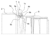
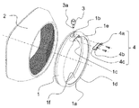
樹脂成型により形成されるアクセサリ取付枠1には、光学アクセサリとしてレンズフード2が装着されている。アクセサリ取付枠1には内径部1aと、内径部1aの略中心方向に向けてアクセサリ取付枠の外径から内径に貫通する雌ネジ(雌ねじ部)1bが設けられる。雌ネジ1bと同じ位相に固定構造収容部1cがアクセサリ取付枠1の内径部1a(径方向内側)と端面1dの一部を光軸方向に切り欠く形で設けられる。さらに、端面1dには固定座面1eが設けられる。ロックネジ(雄ねじ部)3は雌ネジ1bと螺合することで、レンズ装置の光軸に向けた方向(レンズの内径方向)に進退可能に設けられ、ロックネジ3の先端部3aはアクセサリ取付枠の固定構造収容部1cに突き出すように設けられる。弾性部材としての板ばね4は金属製で、固定端4aと可動腕4bとを有し、可動腕4b側の一部には凸部4cが設けられる。板ばね4は、可動腕4bを固定構造収容部1cに挿入した(収容された)状態で、固定端4aを固定座面1eにネジ等の固定手段によって固定することによって、アクセサリ取付枠1に固定される。さらに可動腕4bはロックネジ3の先端部3aと接触可能な位置に回り込む形状を備えている。
A
図2を用いて光学アクセサリとしてレンズフード2をレンズ装置5の被写体側先端付近に取り付ける手順を説明する。
A procedure for attaching the
レンズ装置5の被写体側先端には、アクセサリ取付枠1に挿入される外径部5aとフランジ部5bが設けられ、外径部5aには、外周面に位置決め溝5cが設けられ、位置決め溝5cは外径部5aの一部を全周にわたって切欠いた形状を備える。
An
まず、レンズフード2が取り付けられたアクセサリ取付枠1の内径部1aをレンズ装置5の外径部5aに嵌めた状態で、端面1dがフランジ部5bに当接するまで挿入する。この時、板ばね4の凸部4cの光軸方向の位置は、レンズ装置5の位置決め溝5cの近傍にある。
First, in the state where the
次にロックネジ3を締付け方向に回転させて雌ネジ1bに螺入させると、ロックネジ3の先端部3aが板ばね4の可動腕4bと当接する。ロックネジ3をさらに締め込むと、板ばね4が押圧により変形して、凸部4cが位置決め溝5cに係合して押圧され、レンズフード2がレンズ装置5に固定される。すなわち、板ばね(弾性部材)4、雌ネジ1b、ロックネジ3、固定構造収容部1cは、アクセサリ取付枠1をレンズ装置5に固定するための固定部を構成している。
Next, when the
以上説明したように、本発明の光学アクセサリは、アクセサリ取付枠が樹脂製であるため、ロックネジ(雄ねじ部)の締め込み時には、アクセサリ取付枠がレンズ装置より先に変形する。そのため、レンズ装置の作動が悪化することを防止できる。 As described above, in the optical accessory of the present invention, since the accessory mounting frame is made of resin, the accessory mounting frame is deformed before the lens device when the lock screw (male thread portion) is tightened. Therefore, it is possible to prevent the operation of the lens device from deteriorating.
また、ロックネジ(雄ねじ部)とレンズ装置の間に、アクセサリ取付枠の端面に固定した弾性部材の可動腕を挿入する(介在させる)ことによって、アクセサリ取付枠の内径に溝を設けることなく、固定時のレンズ装置の傷付きを防止できる。 Also, by inserting (interposing) a movable arm of an elastic member fixed to the end face of the accessory mounting frame between the lock screw (male thread part) and the lens device, it is fixed without providing a groove in the inner diameter of the accessory mounting frame. The lens device can be prevented from being damaged at the time.
さらに、図3に例示するように、固定構造収容部を内径部と端面の一部を切り欠く形状にすることによって、単純な型構成(図3中のA,B,C,D)で樹脂成型時に内径部と同時に固定構造収容部の形状を作成することが可能になる。従って、安価なアクセサリ取付枠を提供することが可能になる。 Further, as illustrated in FIG. 3, the fixed structure housing portion is formed into a shape in which a part of the inner diameter portion and the end face is cut out, so that the resin can be formed with a simple mold configuration (A, B, C, D in FIG. 3). At the time of molding, the shape of the fixed structure accommodating portion can be created simultaneously with the inner diameter portion. Therefore, an inexpensive accessory mounting frame can be provided.
さらに、弾性部材の凸部がレンズ装置の位置決め溝と係合するため、アクセサリ取付枠の内径に係止部材を設けることなく、光学アクセサリの光軸方向の係止力を向上させることが可能になる。 Furthermore, since the convex portion of the elastic member engages with the positioning groove of the lens device, the locking force in the optical axis direction of the optical accessory can be improved without providing a locking member on the inner diameter of the accessory mounting frame. Become.
さらに、レンズ装置の位置決め溝と係合する弾性部材が板ばねにより構成されるため、従来の円弧状の係止部材と比較して安価に製作することが可能になる。 Furthermore, since the elastic member that engages with the positioning groove of the lens device is configured by a leaf spring, it can be manufactured at a lower cost than a conventional arc-shaped locking member.
また、例示した本実施例においては、板ばね4の凸部4cは、ロックネジ(雄ねじ部)3を締め込むことにより、ロックネジ3の先端部3aが板ばね4の可動腕4bと当接し、板ばね4が押圧により変形して、凸部4cが位置決め溝5cに係合し、アクセサリ取付枠1がレンズ装置5に固定される構成を説明した。しかし、本発明はこの構成に限定されることはない。アクセサリ取付枠1をレンズ装置の先端に嵌合させることによって、板ばね4を弾性変形で変形させて凸部4cを位置決め溝5cに係合させ、この状態でロックネジ3を締め込むことにより位置決め溝5cに係合している凸部4cをさらに押圧して、アクセサリ取付枠1をレンズ装置5に確実に固定する構成としてもよい。また、例示した本実施例においては、周方向の1箇所において、固定構造収容部1c、雌ネジ(雌ねじ部)1b、弾性部材4、ロックネジ3が構成されて(固定部を構成して)、アクセサリ取付枠1をレンズ装置に固定していたが、本発明はこれに限定されることはない。周方向の複数の箇所に固定部を構成してもよく、少なくなくとも1か所に構成されれば、本発明の効果を享受することができる。
In the illustrated embodiment, the
本実施例では板ばね4が固定される端面1dをカメラ側として、レンズ装置5のフランジ部5bと当接する構造としたが、板ばね4を被写体側の端面に固定しても得られる効果は同じである。
In the present embodiment, the
以下、図4、5を参照して、本発明の第2の実施例による、光学アクセサリについて説明する。 Hereinafter, an optical accessory according to a second embodiment of the present invention will be described with reference to FIGS.
図4において、アクセサリ取付枠1の内径部1aには、アクセサリ取付枠1の材質とは異なる材質からなる摩擦材1fがロックネジ(雄ねじ部)3が設けられる位相の反対側の内周面に、図5に例示するように、少なくとも180°の範囲にわたって一体的に設けられる。摩擦材1fはゴムまたはエラストマーからなり、ゴムの場合は内径部1aに接着により固定され、エラストマーの場合はアクセサリ取付枠1と一体で成型することで固定される。また、摩擦材1fのレンズ装置5の外径部5bとの間の摩擦係数は、アクセサリ取付枠1と外径部5bとの間の摩擦係数より大きいものとする。
4, the
その他の構造は実施例1と同様であるため省略する。 Since other structures are the same as those of the first embodiment, a description thereof will be omitted.
光学アクセサリとしてレンズフード2をレンズ装置5に取り付ける際には、ロックネジ3の締付けにより、ロックネジ3の反対側の内径部1aに力が加わる。内径部1aには摩擦材1fが設けられているため、ロックネジ3の軸力が一定である場合、摩擦材1fが構成されない場合よりも大きな摩擦力が発生する。
When the
以上説明したように、本実施例の光学アクセサリは、実施例1の光学アクセサリと同様の効果が得られると共に、アクセサリ取付枠の内径部に摩擦材を構成することにより、光学アクセサリのレンズ装置への固定をより強固に行うことが可能になる。 As described above, the optical accessory according to the present embodiment can achieve the same effects as those of the optical accessory according to the first embodiment, and the friction material is formed on the inner diameter portion of the accessory mounting frame, so that the lens device of the optical accessory can be obtained. Can be more firmly fixed.
それにより、光学アクセサリをレンズ装置に取り付けた際に、光学アクセサリに外力がかかった場合において、レンズ装置に対する光学アクセサリの位置ずれや、レンズ装置からの脱落が起きにくくなる。 Accordingly, when an external force is applied to the optical accessory when the optical accessory is attached to the lens device, the optical accessory is not easily displaced relative to the lens device or dropped from the lens device.
また、摩擦材をエラストマーによる一体成型により設ける場合、固定の強化だけなく、アクセサリ取付枠の内径部の形状精度の向上が可能になる。 Further, when the friction material is provided by integral molding with an elastomer, it is possible not only to strengthen the fixation but also to improve the shape accuracy of the inner diameter portion of the accessory mounting frame.
ところで、ロックネジ(雄ねじ部)の締め込みでアクセサリ取付枠はロックネジの締め込み方向に向けて略楕円形に変形する。そのため、ロックネジから90°の位相においては、アクセサリ取付枠は内径側に向けて変形する。摩擦材をロックネジの反対側の位相から両側それぞれに対して90°以上の範囲にわたって一体的に設けることにより、摩擦材がアクセサリ取付枠の内径側への変形による力を受けるため、光学アクセサリのレンズ装置への固定をさらに強固に行うことが可能になる。 By the way, when the lock screw (male screw portion) is tightened, the accessory mounting frame is deformed into a substantially oval shape in the lock screw tightening direction. Therefore, in the phase of 90 ° from the lock screw, the accessory mounting frame is deformed toward the inner diameter side. Since the friction material is integrally provided over a range of 90 ° or more with respect to both sides from the opposite phase of the lock screw, the friction material receives a force due to deformation toward the inner diameter side of the accessory mounting frame. It is possible to more firmly fix the device.
また、本実施例では摩擦材1fとレンズフード2を別の部品として説明したが、アクセサリ取付枠1がレンズフード2の専用枠である場合、摩擦材1fとレンズフード2を一体的に成型しても同様の効果が得られる。
In the present embodiment, the
また、本実施例では摩擦材を構成範囲の中に一律に設ける例を示したが、摩擦材を180°以上の範囲に点在させても同様の効果が得られることは言うまでも無い。
本発明の光学アクセサリを備えたレンズ装置、及び、本発明の光学アクセサリを備えたレンズ装置とカメラ装置を含む撮影装置において、本発明の好ましい効果を享受することができる。
In the present embodiment, the example in which the friction material is uniformly provided in the configuration range is shown, but it goes without saying that the same effect can be obtained even if the friction material is scattered in a range of 180 ° or more.
The lens apparatus provided with the optical accessory of the present invention and the photographing apparatus including the lens apparatus provided with the optical accessory of the present invention and the camera apparatus can enjoy the preferable effects of the present invention.
以上、本発明の好ましい実施形態について説明したが、本発明はこれらの実施形態に限定されず、その要旨の範囲内で種々の変形及び変更が可能である。 As mentioned above, although preferable embodiment of this invention was described, this invention is not limited to these embodiment, A various deformation | transformation and change are possible within the range of the summary.
本発明は、レンズのアクセサリに関し、特にレンズの被写体側に取り付けられる光学アクセサリに好適なものである。 The present invention relates to a lens accessory, and is particularly suitable for an optical accessory attached to a subject side of a lens.
1 : アクセサリ取付枠
1b : 雌ネジ(雌ねじ部)
2 : レンズフード(光学アクセサリ)
3 : ロックネジ(雄ねじ部)
4 : 板ばね(弾性部材)
4c: 凸部
5 : レンズ装置
5c: 位置決め溝
1:
2: Lens hood (optical accessory)
3: Lock screw (male thread)
4: Leaf spring (elastic member)
4c: Convex part 5:
Claims (9)
該光学アクセサリは、前記レンズ装置に固定するためのアクセサリ取付枠を有し、
該アクセサリ取付枠は、周方向の少なくとも1か所に、該光学アクセサリを前記レンズ装置に固定するための固定部を有し、
該固定部は、前記アクセサリ取付枠を径方向に貫通する雌ねじ部と、該雌ねじ部に径方向内側に向けて螺合する雄ねじ部と、前記アクセサリ取付枠に端部が固定された弾性部材と、を含み、
前記弾性部材の端部は、前記アクセサリ取付枠の端面に固定され、前記弾性部材の一部には凸部が設けられ、前記雄ねじ部を前記雌ねじ部に螺入させることによって、前記雄ねじ部の先端が前記弾性部材を押圧して前記凸部を前記レンズ装置の前記位置決め溝に押圧することにより、前記光学アクセサリを前記レンズ装置に固定する、
ことを特徴とする光学アクセサリ。 An optical accessory mounted on the subject side of a lens apparatus having a positioning groove formed on an outer peripheral surface,
The optical accessory has an accessory mounting frame for fixing to the lens device,
The accessory mounting frame has a fixing portion for fixing the optical accessory to the lens device in at least one place in the circumferential direction.
The fixing portion includes a female screw portion that penetrates the accessory mounting frame in the radial direction, a male screw portion that is screwed into the female screw portion inward in the radial direction, and an elastic member having an end fixed to the accessory mounting frame. Including,
An end portion of the elastic member is fixed to an end surface of the accessory mounting frame, a convex portion is provided on a part of the elastic member, and the male screw portion is screwed into the female screw portion, thereby The tip is pressed against the elastic member and the convex portion is pressed against the positioning groove of the lens device, thereby fixing the optical accessory to the lens device.
An optical accessory characterized by that.
前記雄ねじ部の先端は、前記固定構造収容部に突き出し、前記弾性部材の前記凸部は前記固定構造収容部に収容される、
ことを特徴とする請求項1に記載の光学アクセサリ。 The accessory mounting frame has a fixed structure housing portion having a shape in which a part of a radially inner end face in the optical axis direction is cut out in the optical axis direction,
The distal end of the male screw portion protrudes into the fixed structure accommodating portion, and the convex portion of the elastic member is accommodated in the fixed structure accommodating portion.
The optical accessory according to claim 1 .
Priority Applications (1)
| Application Number | Priority Date | Filing Date | Title |
|---|---|---|---|
| JP2013224846A JP6289032B2 (en) | 2013-10-30 | 2013-10-30 | Lens optical accessory, and lens apparatus and photographing apparatus having the same |
Applications Claiming Priority (1)
| Application Number | Priority Date | Filing Date | Title |
|---|---|---|---|
| JP2013224846A JP6289032B2 (en) | 2013-10-30 | 2013-10-30 | Lens optical accessory, and lens apparatus and photographing apparatus having the same |
Publications (3)
| Publication Number | Publication Date |
|---|---|
| JP2015087488A JP2015087488A (en) | 2015-05-07 |
| JP2015087488A5 JP2015087488A5 (en) | 2016-12-15 |
| JP6289032B2 true JP6289032B2 (en) | 2018-03-07 |
Family
ID=53050357
Family Applications (1)
| Application Number | Title | Priority Date | Filing Date |
|---|---|---|---|
| JP2013224846A Active JP6289032B2 (en) | 2013-10-30 | 2013-10-30 | Lens optical accessory, and lens apparatus and photographing apparatus having the same |
Country Status (1)
| Country | Link |
|---|---|
| JP (1) | JP6289032B2 (en) |
Family Cites Families (5)
| Publication number | Priority date | Publication date | Assignee | Title |
|---|---|---|---|---|
| JPS59106128U (en) * | 1983-01-06 | 1984-07-17 | 株式会社ニコン | Cover-type lens hood |
| JP3347805B2 (en) * | 1993-04-16 | 2002-11-20 | 富士写真光機株式会社 | Lens hood mounting structure |
| JP2002214679A (en) * | 2001-01-19 | 2002-07-31 | Fuji Photo Film Co Ltd | Lens protecting device |
| JP4314327B2 (en) * | 2003-06-27 | 2009-08-12 | 有限会社梅本製作所 | Optical apparatus mounting apparatus and optical apparatus |
| JP4986501B2 (en) * | 2006-04-28 | 2012-07-25 | 富士フイルム株式会社 | Optical option mounting ring |
-
2013
- 2013-10-30 JP JP2013224846A patent/JP6289032B2/en active Active
Also Published As
| Publication number | Publication date |
|---|---|
| JP2015087488A (en) | 2015-05-07 |
Similar Documents
| Publication | Publication Date | Title |
|---|---|---|
| JP5463651B2 (en) | Camera, camera accessories | |
| JP2006343510A (en) | Lens adapter | |
| US20070297790A1 (en) | Lens accessory mounting device | |
| JP6160323B2 (en) | Lens barrel | |
| JP5228691B2 (en) | Optical device mounting structure and optical device | |
| US20210278040A1 (en) | Protective casing structure, handheld gimbal, and imaging device | |
| US10447904B2 (en) | Lens mount for use in attachment/removal of interchangeable lens, interchangeable lens, and image pickup apparatus | |
| JP6289032B2 (en) | Lens optical accessory, and lens apparatus and photographing apparatus having the same | |
| JP2010256568A (en) | Lens barrel | |
| JP5499828B2 (en) | Imaging device | |
| JP3970670B2 (en) | Camera mounting parts | |
| US20200249550A1 (en) | Adapter apparatus and image pickup apparatus | |
| JP2014052507A (en) | Polarization filter fitting structure | |
| JP2004271892A (en) | Optical accessory lens barrel | |
| WO2005080137A1 (en) | Outer mirror | |
| JP6775819B2 (en) | Lens accessories and lens barrel | |
| US8477438B2 (en) | Lens apparatus | |
| US7630629B2 (en) | Accessory unit and camera system | |
| JP4693384B2 (en) | Lens fixing part structure | |
| CN110824815B (en) | Accessory and image forming apparatus including the same | |
| JP5529243B2 (en) | Fastener | |
| US20230152576A1 (en) | Image pickup apparatus | |
| JP3347805B2 (en) | Lens hood mounting structure | |
| JP2017138367A (en) | Camera module, and camera-attached entrance slave unit | |
| JP3719528B2 (en) | Conversion lens device |
Legal Events
| Date | Code | Title | Description |
|---|---|---|---|
| A521 | Written amendment |
Free format text: JAPANESE INTERMEDIATE CODE: A523 Effective date: 20161027 |
|
| A621 | Written request for application examination |
Free format text: JAPANESE INTERMEDIATE CODE: A621 Effective date: 20161027 |
|
| A977 | Report on retrieval |
Free format text: JAPANESE INTERMEDIATE CODE: A971007 Effective date: 20170621 |
|
| A131 | Notification of reasons for refusal |
Free format text: JAPANESE INTERMEDIATE CODE: A131 Effective date: 20170704 |
|
| A521 | Written amendment |
Free format text: JAPANESE INTERMEDIATE CODE: A523 Effective date: 20170831 |
|
| RD05 | Notification of revocation of power of attorney |
Free format text: JAPANESE INTERMEDIATE CODE: A7425 Effective date: 20171214 |
|
| TRDD | Decision of grant or rejection written | ||
| A01 | Written decision to grant a patent or to grant a registration (utility model) |
Free format text: JAPANESE INTERMEDIATE CODE: A01 Effective date: 20180109 |
|
| A61 | First payment of annual fees (during grant procedure) |
Free format text: JAPANESE INTERMEDIATE CODE: A61 Effective date: 20180206 |
|
| R151 | Written notification of patent or utility model registration |
Ref document number: 6289032 Country of ref document: JP Free format text: JAPANESE INTERMEDIATE CODE: R151 |