JP6287630B2 - Image reading apparatus, image forming apparatus, and image reading method - Google Patents
Image reading apparatus, image forming apparatus, and image reading method Download PDFInfo
- Publication number
- JP6287630B2 JP6287630B2 JP2014131532A JP2014131532A JP6287630B2 JP 6287630 B2 JP6287630 B2 JP 6287630B2 JP 2014131532 A JP2014131532 A JP 2014131532A JP 2014131532 A JP2014131532 A JP 2014131532A JP 6287630 B2 JP6287630 B2 JP 6287630B2
- Authority
- JP
- Japan
- Prior art keywords
- distortion
- image
- reading
- subject
- distortion data
- Prior art date
- Legal status (The legal status is an assumption and is not a legal conclusion. Google has not performed a legal analysis and makes no representation as to the accuracy of the status listed.)
- Active
Links
- 238000000034 method Methods 0.000 title claims description 50
- 238000012937 correction Methods 0.000 claims description 41
- 238000006243 chemical reaction Methods 0.000 claims description 16
- 239000000463 material Substances 0.000 claims description 2
- 238000010586 diagram Methods 0.000 description 24
- 230000004075 alteration Effects 0.000 description 10
- 230000003287 optical effect Effects 0.000 description 10
- 230000006399 behavior Effects 0.000 description 7
- 238000012546 transfer Methods 0.000 description 7
- 238000003384 imaging method Methods 0.000 description 6
- 239000011521 glass Substances 0.000 description 5
- 238000004519 manufacturing process Methods 0.000 description 5
- 230000007274 generation of a signal involved in cell-cell signaling Effects 0.000 description 4
- 239000003086 colorant Substances 0.000 description 3
- 230000002093 peripheral effect Effects 0.000 description 3
- 230000005540 biological transmission Effects 0.000 description 2
- 239000000428 dust Substances 0.000 description 2
- 230000000694 effects Effects 0.000 description 2
- 230000006870 function Effects 0.000 description 2
- 238000013461 design Methods 0.000 description 1
- 238000007599 discharging Methods 0.000 description 1
- 238000012545 processing Methods 0.000 description 1
- 238000007665 sagging Methods 0.000 description 1
- 238000000926 separation method Methods 0.000 description 1
- 230000003068 static effect Effects 0.000 description 1
- 238000011144 upstream manufacturing Methods 0.000 description 1
Images


Description
本発明は、画像読取装置、画像形成装置及び画像読取方法に関する。 The present invention relates to an image reading apparatus, an image forming apparatus, and an image reading method.
CCDやCMOSイメージセンサ等を用いた画像読取装置では、使用するレンズの収差特性により、画像が歪曲するディストーションという現象が生じる。ディストーションは、主にエリアセンサを用いたデジタルカメラ等の撮像装置において、理想結像位置に対して広がる、又は狭まる歪みで目立つものとなる。また、ディストーションは、レンズの製造誤差、及び個体差などによって生じるものであり、レンズ毎にディストーション量は異なる。これらのディストーションを補正するために、レンズ個体毎にディストーション量を測定し、メモリに保存したディストーション量を参照することによって補正を行う方法などが知られている。 In an image reading apparatus using a CCD, a CMOS image sensor, or the like, a phenomenon called distortion occurs in which an image is distorted due to the aberration characteristics of a lens used. Distortion is conspicuous in a distortion that spreads or narrows with respect to an ideal imaging position in an imaging apparatus such as a digital camera that mainly uses an area sensor. Further, distortion is caused by a manufacturing error of the lens, individual differences, and the like, and the amount of distortion differs for each lens. In order to correct these distortions, a method is known in which the amount of distortion is measured for each individual lens and correction is performed by referring to the amount of distortion stored in a memory.
また、特許文献1には、歪曲収差特性曲線に基づいて歪曲収差補正曲線を作成し、測距した被写体距離が記憶してある被写体距離と合致していないと判断した場合には、その被写体距離の前後に相当する被写体距離を補間して各像位置毎の歪曲収差値を演算し、歪曲収差を補正する歪曲収差補正装置が開示されている。
In
しかしながら、固定した原稿と、搬送している原稿とを読取可能にされた画像読取装置においては、固定した原稿に対して搬送時の原稿の読取り距離が変化すると、主走査倍率が変化して、画像の歪曲を適切に補正することができないという問題があった。 However, in an image reading apparatus capable of reading a fixed original and a conveyed original, if the reading distance of the original during conveyance changes with respect to the fixed original, the main scanning magnification changes, There has been a problem that image distortion cannot be corrected appropriately.
本発明は、上記に鑑みてなされたものであって、被写体の読取り距離が変化しても、画像の歪曲を適切に補正することができる画像読取装置、画像形成装置及び画像読取方法を提供することを目的とする。 The present invention has been made in view of the above, and provides an image reading apparatus, an image forming apparatus, and an image reading method capable of appropriately correcting image distortion even when the reading distance of a subject changes. For the purpose.
上述した課題を解決し、目的を達成するために、本発明は、レンズを介して被写体からの反射光を光電変換するイメージセンサにより、固定された被写体を読取る第1読取方式と、搬送されて移動する被写体を読取る第2読取方式とによって被写体を読取可能にされた画像読取装置であって、前記第1読取方式における主走査方向の前記レンズによる第1ディストーションデータ、及び、前記第1読取方式における前記レンズと前記被写体との距離と、前記第2読取方式における前記レンズと前記被写体との定常的な距離の差によって生じる所定倍率差とを記憶する記憶部と、前記第1ディストーションデータ及び前記所定倍率差を用いて、前記第1ディストーションデータを前記第2読取方式に対応する第2ディストーションデータに変換するデータ変換部と、前記第2ディストーションデータを用いて、前記第2読取方式における主走査方向のディストーションを補正する補正部と、を有することを特徴とする。 In order to solve the above-described problems and achieve the object, the present invention is conveyed with a first reading method for reading a fixed subject by an image sensor that photoelectrically converts reflected light from the subject via a lens. An image reading apparatus capable of reading a subject by a second reading method for reading a moving subject, the first distortion data by the lens in the main scanning direction in the first reading method, and the first reading method A storage unit that stores a distance between the lens and the subject in the second reading method, a predetermined magnification difference caused by a difference in a steady distance between the lens and the subject in the second reading method, the first distortion data, and the Converting the first distortion data into second distortion data corresponding to the second reading method using a predetermined magnification difference A data conversion section that, using the second distortion data, and having a correction unit for correcting the main scanning direction of the distortion in the second reading method.
本発明によれば、被写体の読取り距離が変化しても、画像の歪曲を適切に補正することができるという効果を奏する。 According to the present invention, there is an effect that image distortion can be appropriately corrected even when the subject reading distance changes.
以下に添付図面を参照して、実施形態にかかる画像形成装置を説明する。図1は、実施形態にかかる画像形成装置300の構成例を示す構成図である。画像形成装置300は、給紙部303及び画像形成装置本体(画像形成部)304を有し、上部に画像読取装置100及び自動原稿給送装置(ADF)200が搭載されたデジタル複合機である。なお、画像読取装置100は、ADF200が一体となって単体の画像読取装置となるように構成されてもよい。
An image forming apparatus according to an embodiment will be described below with reference to the accompanying drawings. FIG. 1 is a configuration diagram illustrating a configuration example of an
画像形成装置本体304内には、タンデム方式の作像部305と、給紙部303から搬送路307を介して供給される記録紙(記録媒体)を作像部305に搬送するレジストローラ308と、光書き込み装置309と、定着搬送部310と、両面トレイ311とが設けられている。
In the image forming apparatus
作像部305には、Y,M,C,Kの4色のトナーに対応して4本の感光体ドラム312が並設されている。各感光体ドラム312の回りには、帯電器、現像器306、転写器、クリーナ、及び除電器を含む作像要素が配置されている。
In the
また、転写器と感光体ドラム312との間には両者のニップに挟持された状態で駆動ローラと従動ローラとの間に張架された中間転写ベルト313が配置されている。
In addition, an
このように構成されたタンデム方式の画像形成装置300は、Y,M,C,Kの色毎に各色に対応する感光体ドラム312に光書き込みを行い、現像器306で各色のトナー毎に現像し、中間転写ベルト313上に例えばY,M,C,Kの順に1次転写を行う。
The tandem
そして、画像形成装置300は、1次転写により4色重畳されたフルカラーの画像を記録紙に2次転写した後、定着して排紙することによりフルカラーの画像を記録紙上に形成する。また、画像形成装置300は、画像読取装置100が読取った画像を記録紙上に形成する。
Then, the
図2は、画像読取装置100及びADF200の構成例を示す構成図である。画像読取装置100は、デジタル複写機、デジタル複合機、ファクシミリ装置等の画像形成装置に搭載されるスキャナ装置である。そして、画像読取装置100は、光源からの照射光によって被写体(読取対象)である原稿を照明し、その原稿からの反射光を光電変換するCMOSイメージセンサで受光した信号に処理を行い、原稿の画像データを読み取る。
FIG. 2 is a configuration diagram illustrating a configuration example of the
具体的には、画像読取装置100は、図2に示すように、原稿(被写体)を載置するコンタクトガラス101と、原稿露光用の光源102及び第1反射ミラー103を具備する第1キャリッジ106と、第2反射ミラー104及び第3反射ミラー105を具備する第2キャリッジ107とを有する。また、画像読取装置100は、RGBのカラーセンサであるイメージセンサ109と、イメージセンサ109に結像するためのレンズユニット(レンズ)108と、読取り光学系等による各種の歪みを補正するためなどに用いる基準白板(白基準板)110と、シートスルー読取り用のスリット111も備えている。
Specifically, as shown in FIG. 2, the
画像読取装置100は、上部にADF200が搭載されており、このADF200をコンタクトガラス101に対して開閉できるように、図示しないヒンジ等を介した連結がなされている。
The
ADF200は、複数枚の原稿からなる原稿束を載置可能な原稿載置台としての原稿トレイ201を備えている。また、ADF200は、原稿トレイ201に載置された原稿束から原稿を1枚ずつ分離してスリット111へ向けて自動給送する給送ローラ202を含む分離・給送手段も備えている。
The ADF 200 includes a
さらに、スリット111の原稿搬送方向上流側には、ガイド部材112が設けられている。ガイド部材112は、スリット111に対する汚れやゴミの付着を防止するために、後述する原稿搬送読取時にスリット111へ原稿を接触させないようにしている。
Further, a
そして、画像読取装置100は、固定された原稿の画像面をスキャン(走査)して原稿の画像を読み取るフラットベッド読み取りモード(以下、圧板読取と記載)時には、第1キャリッジ106及び第2キャリッジ107により、図示しないステッピングモータによって矢示A方向(副走査方向)に原稿を走査する。このとき、コンタクトガラス101からイメージセンサ109までの光路長を一定に維持するために、第2キャリッジ107は第1キャリッジ106の1/2の速度で移動する。
The
同時に、コンタクトガラス101上にセットされた原稿の下面である画像面が第1キャリッジ106の光源102によって照明(露光)される。すると、その画像面からの反射光像が第1キャリッジ106の第1反射ミラー103、第2キャリッジ107の第2反射ミラー104及び第3反射ミラー105、並びにレンズユニット108経由でイメージセンサ109へ順次送られて結像される。
At the same time, the image surface which is the lower surface of the document set on the
そして、イメージセンサ109の光電変換により信号が出力され、出力された信号はデジタル信号に変換される。このように、原稿の画像が読み取られ、デジタルの画像データが得られる。
Then, a signal is output by photoelectric conversion of the
一方、原稿を自動給送して原稿の画像を読み取るシートスルー読み取りモード(以下、原稿搬送読取と記載)時には、第1キャリッジ106及び第2キャリッジ107が、スリット111の下側へ移動する。その後、原稿トレイ201に載置された原稿が給送ローラ202によって矢示B方向(副走査方向)へ自動給送され、スリット111の位置において原稿が走査される。
On the other hand, in a sheet-through reading mode (hereinafter referred to as “document feed reading”) in which an original is automatically fed and an image of the original is read, the
このとき、搬送される原稿の下面(画像面)が第1キャリッジ106の光源102によって照明される。そのため、その画像面からの反射光像が第1キャリッジ106の第1反射ミラー103、第2キャリッジ107の第2反射ミラー104及び第3反射ミラー105、並びにレンズユニット108経由でイメージセンサ109へ順次送られて結像される。そして、イメージセンサ109の光電変換により信号が出力され、出力された信号はデジタル信号に変換される。このように、原稿の画像が読み取られ、デジタルの画像データが得られる。画像の読み取りが完了した原稿は、図示しない排出口に排出される。
At this time, the lower surface (image surface) of the conveyed document is illuminated by the
図3は、画像読取装置100が有する機能の要部を示す機能ブロック図である。光源102は、照射光を原稿に対して照射する。イメージセンサ109は、原稿からの反射光を光電変換し、デジタル画像信号として出力する。なお、イメージセンサ109は、内部に図示しない複数の受光素子が主走査方向に配列されたラインセンサである。イメージセンサ109は、各画素に相当する各受光素子が、光源102からの反射光を電気信号に変換し、図示しない増幅器やA/D変換器によってデジタル画素データを得る。また、イメージセンサ109は、各受光素子からのパラレルデータであるデジタル画素データをシリアルデータに変換し、同期信号生成部503からのライン同期信号に同期して、ライン毎にデジタル画素データをディストーション補正部502に対して伝送する。
FIG. 3 is a functional block diagram illustrating a main part of the functions of the
メモリ(記憶部)500は、予め画像読取装置100の製造工程等において測定された離散的な主走査方向の各画素のディストーションデータが格納されている。メモリ500が格納しているディストーションデータは、圧板読取(第1読取方式)時のディストーション量に対応している。さらに、メモリ500は、予め画像読取装置100の製造工程等において測定された離散的な副走査方向の倍率誤差データも格納されている。メモリ500は、ディストーションデータ及び倍率誤差データを、同期信号生成部503からのライン同期信号に同期して、ライン毎にディストーション補正部502に対して伝送する。なお、ディストーションデータ及び倍率誤差データの詳細については後述する。
The memory (storage unit) 500 stores the distortion data of each pixel in the discrete main scanning direction measured in advance in the manufacturing process of the
切替部501は、例えばセンサを備え、原稿トレイ201上の原稿の有無を検知する。画像読取装置100は、切替部501が原稿トレイ201上の原稿を検知すると、原稿搬送読取(第2読取方式)を行う。また、画像読取装置100は、切替部501が原稿トレイ201上の原稿を検知しない場合には、圧板読取を行う。ここで、切替部501は、原稿トレイ201上の原稿の有無に応じて、原稿搬送読取又は圧板読取のいずれかに切替える切替信号をディストーション補正部502に対して出力する。
The
ディストーション補正部502は、メモリ500が格納しているディストーションデータ及び倍率誤差データを受入れ、切替信号に応じて、ディストーションデータをそのまま用いるか、又はディストーションデータを倍率誤差データよって変換して用いるかを切り替える。そして、ディストーション補正部502は、イメージセンサ109から受入れた主走査方向の全画素(デジタル画像データ)の主走査ずれを補正し、後段に転送する。なお、ディストーション補正部502の詳細については後述する。
The
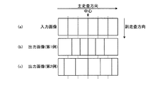
図4は、ラインセンサにおける歪曲収差を示す図である。図4(a)は画像読取装置に対する入力画像であり、図4(b),(c)は画像読取装置が読取った結果である出力画像(第1例、第2例)である。 FIG. 4 is a diagram illustrating distortion aberration in the line sensor. 4A is an input image to the image reading apparatus, and FIGS. 4B and 4C are output images (first example and second example) obtained as a result of reading by the image reading apparatus.
ラインセンサを用いた画像読取装置においては、レンズの特性により、図4(a)に示した理想結像位置に対して、図4(b)に示した主走査方向の間隔(位置)が狭まる歪み、又は図4(c)に示した主走査方向の間隔(位置)が広がる歪みが発生する場合がある。これが歪曲収差(ディストーション)である。また、レンズの製造バラつき等の影響により、レンズ個体毎にディストーション量は異なる。 In an image reading apparatus using a line sensor, the interval (position) in the main scanning direction shown in FIG. 4B is narrower than the ideal imaging position shown in FIG. There is a case where a distortion or a distortion in which the interval (position) in the main scanning direction shown in FIG. This is distortion. In addition, the amount of distortion varies from lens to lens due to the effects of lens manufacturing variation.
図5は、ディストーション量、及びディストーションを補正するためのディストーションデータを例示する図である。なお、図5(a)には生成されるディストーションカーブが示され、図5(b)には保存されるディストーションデータ(第1ディストーションデータ)が示され、図5(c)には補間により算出されるディストーションデータが示されている。ディストーションデータは、上述したようにメモリ500に保存される。
FIG. 5 is a diagram illustrating the distortion amount and the distortion data for correcting the distortion. 5A shows the generated distortion curve, FIG. 5B shows the stored distortion data (first distortion data), and FIG. 5C shows the calculation by interpolation. The distortion data to be displayed is shown. The distortion data is stored in the
画素毎の理想位置からのずれ量を示すディストーションカーブを生成(抽出)する場合、まず、画像読取装置の製造工程において、専用の原稿を上述した圧板読取によって読み取る。これにより、主走査方向の全画素における理想結像位置からのディストーション量を求める。 When generating (extracting) a distortion curve indicating the amount of deviation from the ideal position for each pixel, first, in the manufacturing process of the image reading apparatus, a dedicated document is read by the above-described pressure plate reading. Thereby, the amount of distortion from the ideal imaging position in all pixels in the main scanning direction is obtained.
例として、図5(a)に示したディストーションカーブが生成されたとする。なお、ディストーション量がプラスの値では理想結像位置より主走査プラス方向にずれが発生していることを意味し、ディストーション量がマイナスの値では理想結像位置より主走査マイナス方向にずれが発生していることを意味する。 As an example, assume that the distortion curve shown in FIG. If the distortion amount is a positive value, it means that there is a deviation in the main scanning plus direction from the ideal imaging position. If the distortion amount is a negative value, a deviation occurs in the main scanning minus direction from the ideal imaging position. Means that
画像読取装置100は、生成したディストーションカーブに対し、図5(b)に示すように、主走査方向の複数の任意の画素位置と、その画素位置に対応するディストーション量のデータをメモリ500に保存する。なお、保存するデータの個数は、メモリ500の容量に応じて、画素位置はレンズの収差特性に応じて、設計段階で予め設定されている。基本的には、レンズ外側の方が内側よりも収差が大きく、ディストーションカーブの変動も大きい為、主走査方向の先後端を密に、主走査方向の中心を粗にするように、データを保存する画素位置が設定される。このように、メモリ500は、イメージセンサ109が読取る主走査方向の全画素中の予め選択された画素に対するディストーションデータを記憶する。
As shown in FIG. 5B, the
ディストーション補正部502は、ディストーション補正を行う場合、メモリ500に保存されたディストーション量を用いて補間することにより、図5(c)に示すように、画素毎のディストーション量を算出する。
When performing distortion correction, the
具体的には、ディストーション補正において、ディストーション補正部502は、メモリ500に保存されたディストーションデータを用いて、入力される画素データをずれ量分だけ画素移動させる。ここで、ディストーション補正部502は、保存されていない主走査方向の画素位置のディストーション量を補間により求める。補間には、例えば演算が容易な線形補間が用いられる。
Specifically, in the distortion correction, the
図6は、主走査方向の線形補間の方法を示す図である。下式1は、補間方法を示す式である。
FIG. 6 is a diagram showing a method of linear interpolation in the main scanning direction. The following
X=dist[i]+(dist[i+1]-dist[i])×(n-dist_add[i])/(dist_add[i+1]-dist_add[i])
・・・(1)
X = dist [i] + (dist [i + 1] -dist [i]) × (n-dist_add [i]) / (dist_add [i + 1] -dist_add [i])
... (1)
補間によって主走査方向の全画素のディストーションデータが得られると、各入力画素に対して、ディストーション量分だけずらした画素位置に補正をかけることができ、出力画像は理想位置で再現される。例えば、ディストーション補正部502は、各ずれ量に応じて、周辺画素のデータを用いた3次コンボリューション法により、各画素値を求め、補正を行う。
When the distortion data of all the pixels in the main scanning direction is obtained by the interpolation, the pixel position shifted by the distortion amount can be corrected for each input pixel, and the output image is reproduced at the ideal position. For example, the
図6に示した例では、ディストーションカーブが1本であり、単色(*:RGBいずれか)を想定した記載となっている。画像読取装置100は、RGBのカラーセンサであるイメージセンサ109に対し、R/G/Bそれぞれのディストーションカーブを生成後、同様にR/G/Bそれぞれのディストーション量をメモリ500に保存し、ディストーション補正部502によってR/G/Bそれぞれの補正を行う。
In the example shown in FIG. 6, there is one distortion curve, and the description assumes a single color (*: any of RGB). The
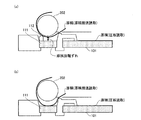
次に、原稿搬送読取において、画像読取装置100が行うディストーション補正について説明する。図7は、原稿搬送読取時の原稿の挙動を示す図である。図7(a)には、画像読取装置100のガイド部材112の周辺における原稿の挙動が示されている。図7(b)は、ガイド部材112が設けられていない場合の原稿の挙動が示されている。上述したように、原稿搬送読取は、ADF200によって原稿を搬送し、画像を読取る方式であり、スリット111に搬送された原稿の先端から読取を行う。
Next, distortion correction performed by the
図7(a)に示すように、画像読取装置100は、ガイド部材112によって原稿を案内することにより、原稿をスリット111の部材上面に接触させることなく搬送する(原稿非接触搬送)。上述したように、ガイド部材112は、原稿のゴミや汚れ(インク)などがスリット111へ付着することを防止するために設けられている。
As shown in FIG. 7A, the
ガイド部材112が設けられていない場合、図7(b)に示すように、原稿は、スリット111に接触して搬送される(原稿接触搬送)。この場合、イメージセンサ109までの光路長(及び原稿からレンズまでの距離:原稿距離)は、圧板読取時と変わらない。原稿非接触搬送時においては、原稿がスリット111から浮いている分、画像を読取ったときに倍率誤差が生じる。
When the
図8は、原稿非接触搬送時に倍率誤差(倍率差)が生じる原理を模式的に示す模式図である。原稿非接触搬送時において、原稿がスリット111から浮いていると、図8にも示すように、圧板読取に対して原稿距離にずれが生じる。原稿距離が変化すると、イメージセンサ109に入力される像が倍率誤差によって主走査方向で変化する。
FIG. 8 is a schematic diagram schematically showing the principle that a magnification error (magnification difference) occurs during document non-contact conveyance. If the document is lifted from the
具体的には、図2に示した画像読取装置100において、図7(a)で示したように、原稿非接触搬送を行って画像を読取る場合、圧板読取時よりも原稿からレンズまでの距離が長くなるため、イメージセンサ109での像は、倍率誤差により狭まることになる。このため、原稿非接触搬送を行った場合に、圧板読取時のディストーションデータをそのまま用いると、倍率誤差分、主走査方向にずれが生じてしまう。よって、原稿距離のずれ分だけ、ディストーションデータも変える必要がある。
Specifically, in the
図9は、原稿接触搬送(通常)時のディストーションデータと、原稿非接触搬送(変換)時のディストーションデータを示す図である。図8に示したように、原稿非接触搬送によって画像を読取る場合には、原稿接触搬送によって画像を読取る場合に対して倍率誤差が生じる。つまり、図5を用いて説明した手順で圧板読取時にメモリ500に保存したディストーションデータ(以下、通常ディストーションデータと記載)では、十分にディストーション補正を行うことができない。
FIG. 9 is a diagram showing distortion data during document contact conveyance (normal) and distortion data during document non-contact conveyance (conversion). As shown in FIG. 8, when an image is read by non-contact conveyance of a document, a magnification error is generated as compared with the case of reading an image by document contact conveyance. That is, the distortion data (hereinafter referred to as normal distortion data) stored in the
原稿非接触搬送によって画像を読取る場合、ディストーション補正部502は、通常ディストーションデータを倍率誤差(所定倍率差)に応じて変換し、新しいディストーションデータ(以下、変換ディストーションデータと記載)を生成する。図8にも示したように、原稿距離ずれによって倍率が変化する場合、イメージセンサ109上の光学中心画素から主走査方向に距離が遠くなるほど、倍率誤差により発生するディストーション量の変化は線形的に大きくなる。つまり、変換ディストーションデータは、下式2によって算出される。なお、原稿接触搬送(通常)時の倍率と、圧板読取時の倍率とは、同じになるとみなしてもよい。つまり、倍率誤差(所定倍率差)は、第1読取方式におけるレンズと被写体との距離と、第2読取方式におけるレンズと被写体との定常的な距離の差によって生じる倍率差である。
When the image is read by non-document conveyance, the
変換ディストーションデータ[x]
=通常ディストーションデータ[x]+(光学中心画素‐x)×(倍率誤差[%]/100)
・・・(2)
Conversion distortion data [x]
= Normal distortion data [x] + (Optical center pixel-x) x (Magnification error [%] / 100)
... (2)
上式2において、xは、主走査方向の画素位置である。x画素目に相当する変換ディストーションデータを求めるためには、光学中心画素から、主走査画素位置xを引き、これに倍率誤差分をかけて、通常ディストーションデータに加算する。 In Expression 2, x is a pixel position in the main scanning direction. In order to obtain conversion distortion data corresponding to the x-th pixel, the main scanning pixel position x is subtracted from the optical center pixel, multiplied by a magnification error, and added to the normal distortion data.
例として、図5に示したメモリ保存ディストーションデータ(□で示した通常ディストーションデータ)が、図9に示した座標上の値をとるものとする。原稿非接触搬送時の倍率誤差は、例えば0.2%であるとする。また、光学中心画素は、主走査方向の端部から3500個目の画素であるとする。これらの値を上式2に当てはめると、各画素位置の変換ディストーションデータは図9に△で示された値となる。つまり、倍率誤差が発生する場合、光学中心画素位置ではディストーション量は変化せず、主走査方向の端部側になるほどディストーション量は線形的に大きくなる。 As an example, it is assumed that the memory-stored distortion data (normal distortion data indicated by □) shown in FIG. 5 takes the values on the coordinates shown in FIG. The magnification error at the time of document non-contact conveyance is assumed to be 0.2%, for example. The optical center pixel is assumed to be the 3500th pixel from the end in the main scanning direction. When these values are applied to the above equation 2, the converted distortion data at each pixel position is the value indicated by Δ in FIG. That is, when a magnification error occurs, the amount of distortion does not change at the optical center pixel position, and the amount of distortion increases linearly toward the end in the main scanning direction.
倍率誤差は、図7(a)に示された画像読取装置100の機械的な構成によって定まる。従って、圧板読取時に対する原稿距離のずれ量は、例えば予め固定値として設定され得る。ディストーション補正部502は、メモリ500に保存されている原稿非接触搬送時の倍率誤差値を用いて、変換ディストーションデータを算出する。
The magnification error is determined by the mechanical configuration of the
次に、原稿非接触搬送によって原稿を読取る場合の原稿の搬送開始時から終了時までの挙動について説明する。図7(a)に示した例では、原稿非接触搬送時には、圧板読取時に対する原稿距離のずれが略一定であるとしている。 Next, the behavior from the start to the end of document conveyance when the document is read by document non-contact conveyance will be described. In the example shown in FIG. 7A, it is assumed that the deviation of the document distance with respect to the pressure plate reading is substantially constant during the document non-contact conveyance.
図10は、原稿非接触搬送によって原稿を読取る場合の原稿の搬送開始時の挙動を示す図である。図10に示すように、画像読取装置100が原稿非接触搬送を行う場合、原稿の副走査方向先端がスリット111に接触してしまう期間(原稿の搬送開始時)が存在する。また、原稿の副走査方向後端もスリット111に接触してしまう期間(原稿の搬送終了時)が存在する。つまり、画像読取装置100は、原稿の搬送開始から終了までの間に、一定の原稿距離で原稿を読み取っているわけではない。
FIG. 10 is a diagram illustrating a behavior at the start of document conveyance when a document is read by document non-contact conveyance. As shown in FIG. 10, when the
ADF200は、給送ローラ202及び図示しない複数の搬送ローラにより、原稿を搬送する。図10に示した原稿搬送読取時の原稿(実線)ように、原稿先端がまだスリット111の下流側に設けられた搬送ローラに到達していない場合は、原稿がたるんだままスリット111を通過することになる。
The
その後、スリット111の下流側に設けられた図示しない搬送ローラに原稿先端が到達すると、原稿先端に張力が加わり、図10に点線で示した原稿のようにたるみが徐々になくなり、図7(a)に示したようにスリット111から略一定距離だけ離れて原稿搬送が行われる。
Thereafter, when the leading end of the document reaches a conveyance roller (not shown) provided on the downstream side of the
原稿後端(原稿の搬送終了時)においても同様に、原稿の後端側がスリット111に到達すると、たるみによりスリット111に原稿が接触する。
Similarly, at the trailing edge of the document (at the end of document transportation), when the trailing edge of the document reaches the
このように、原稿の先後端では、原稿距離が安定していない。よって、画像読取装置100は、図9に示したように副走査方向の全ラインに、一定の倍率誤差で算出した変換ディストーションデータを用いると、原稿の先後端では適切なディストーション補正が行えないことになる。
Thus, the document distance is not stable at the leading and trailing edges of the document. Therefore, the
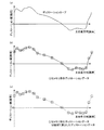
図11は、原稿の副走査方向のライン位置毎に倍率誤差を例示したグラフである。図10を用いて説明したように、原稿の先後端では原稿距離のずれが安定していない。よって、原稿の先後端で適切なディストーション補正を行うためには、各ラインに対する原稿距離のずれ量から倍率誤差(変動倍率差)を把握する必要がある。 FIG. 11 is a graph illustrating the magnification error for each line position in the sub-scanning direction of the document. As described with reference to FIG. 10, the deviation of the document distance is not stable at the leading and trailing edges of the document. Therefore, in order to perform appropriate distortion correction at the leading and trailing edges of the document, it is necessary to grasp the magnification error (variation magnification difference) from the amount of document distance deviation with respect to each line.
搬送される原稿に対しては、図11に示したように、ラインの位置に応じて倍率誤差が変化(原稿距離が変化)するものとする。なお、副走査方向における倍率誤差の変化は、画像読取装置100の機械的な構成や、原稿の搬送速度などによって異なる。例えば、画像読取装置100は、図11に示したような副走査方向の倍率誤差特性が予め測定されている。
As shown in FIG. 11, it is assumed that the magnification error changes (the document distance changes) according to the position of the line for the conveyed document. Note that the change in magnification error in the sub-scanning direction varies depending on the mechanical configuration of the
そして、画像読取装置100は、測定された副走査方向の倍率誤差の特性に対し、任意の複数のライン位置を選択して、選択したライン位置と、ライン位置に対応する倍率誤差(変動倍率差)をメモリ500に保存しておく。ここで、画像読取装置100は、任意に選択するラインを、安定していない原稿先後端に対して密になるように選択する。さらに、副走査方向の倍率誤差が、原稿の紙質や厚さ等により変化するため、画像読取装置100は、原稿の紙種(材質)毎に副走査方向の倍率誤差データをメモリ500に保存しておいてもよい。
Then, the
このように、画像読取装置100は、メモリ500に保存されたライン位置と、ライン位置に相当する倍率誤差データを用いて、読取ライン毎に上式2の倍率誤差も変化させることにより、1枚の原稿読取(1フレーム)内で原稿距離のずれが変化しても、最適な補正が可能となっている。なお、画像読取装置100は、保存したライン間の倍率誤差データを、例えば下式3を用いて図12に示したように線形補間により求める。図12は、副走査方向の線形補間の方法を示す図である。
As described above, the
y=dia[j]+(dia[j+1]-dia[i])×(m-line_add[j])/(line_add[j+1]-line_add[j])
・・・(3)
y = dia [j] + (dia [j + 1] -dia [i]) × (m-line_add [j]) / (line_add [j + 1] -line_add [j])
... (3)
次に、上述したディストーション補正を行うディストーション補正部502の具体的な構成について説明する。図13は、ディストーション補正部502の構成例を示すブロック図である。ディストーション補正部502は、補正部400、副走査補間部401、セレクタ402、データ変換部403及び主走査補間部404を有する。
Next, a specific configuration of the
副走査補間部401は、図11を用いて説明した副走査方向の線形補間を行う。つまり、副走査補間部401は、メモリ500に保存されている離散的なラインの倍率誤差データ(変動倍率差)を用いて線形補間を行い、同期信号生成部503からのライン同期信号に応じて、ライン毎の倍率誤差データをデータ変換部403に対して出力する。
The
セレクタ402は、図3に示した切替部501からの切替信号に応じて、圧板読取又は原稿搬送読取のいずれが実行されるかを判断し、メモリ500に保存されているディストーションデータを、データ変換部403を介して主走査補間部404に伝達するか、又はそのまま主走査補間部404に伝達するかを切替える。つまり、切替部501は、第1読取方式により被写体を読取る場合には、第1ディストーションデータを用いて補正部400が主走査方向のディストーションを補正し、第2読取方式により被写体を読取る場合には、第2ディストーションデータを用いて補正部400が主走査方向のディストーションを補正するように切替える。
The
データ変換部403は、セレクタ402が原稿搬送読取の実行と判断した場合、副走査補間部401が出力した倍率誤差データを用いて、メモリ500が保存しているディストーションデータを、図9に示したように上式2によって変換ディストーションデータに変換する。また、データ変換部403は、第1ディストーションデータ及び所定倍率差を用いて、第1ディストーションデータを第2読取方式に対応する第2ディストーションデータに変換する。つまり、データ変換部403は、メモリ500が保存している第1ディストーションデータ、所定倍率差及び変動倍率差を用いて、第1ディストーションデータを第2読取方式に対応する第2ディストーションデータに変換する。
The
主走査補間部404は、入力されたディストーションデータを用いて、図5(c)に示したように、主走査方向の0画素目から順に主走査方向の全画素のディストーションデータを補間により算出し、補正部400に対して出力する。即ち、主走査補間部404は、予め選択された画素に対する第1ディストーションデータを用いて、主走査方向の予め選択されていない画素に対する第1ディストーションデータを線形補間によって補間する。
As shown in FIG. 5C, the main
補正部400は、イメージセンサ109が出力した画素データを、主走査補間部404から受入れたディストーションデータに応じて、画素位置毎にディストーションを補正する。また、補正部400は、第2ディストーションデータを用いて、第2読取方式における主走査方向のディストーションを補正する。また、補正部400は、画素位置のずれ量に応じて周辺画素より画素値を算出する3次コンボリューション法を用いた演算回路を含んでおり、最終的な出力画像を得る。
The
なお、例えば画像読取装置100が、図7(b)に示したようにガイド部材112を設けられていない場合には、セレクタ402は切り替えを行わない。この場合、メモリ500に保存されているディストーションデータがそのまま主走査補間部404に入力されるように、例えばレジスタなどが設定される。また、画像読取装置100は、原稿の紙種に応じてメモリ500が保存している倍率誤差データを切り替えるためのレジスタ設定などがなされていてもよい。
For example, when the
100 画像読取装置
101 コンタクトガラス
102 光源
108 レンズユニット
109 イメージセンサ
111 スリット
112 ガイド部材
200 ADF
202 給送ローラ
300 画像形成装置
304 画像形成装置本体(画像形成部)
400 補正部
401 副走査補間部
402 セレクタ
403 データ変換部
404 主走査補間部
500 メモリ
501 切替部
502 ディストーション補正部
503 同期信号生成部
DESCRIPTION OF
202
400
Claims (10)
前記第1読取方式における主走査方向の前記レンズによる第1ディストーションデータ、及び、前記第1読取方式における前記レンズと前記被写体との距離と、前記第2読取方式における前記レンズと前記被写体との定常的な距離の差によって生じる所定倍率差とを記憶する記憶部と、
前記第1ディストーションデータ及び前記所定倍率差を用いて、前記第1ディストーションデータを前記第2読取方式に対応する第2ディストーションデータに変換するデータ変換部と、
前記第2ディストーションデータを用いて、前記第2読取方式における主走査方向のディストーションを補正する補正部と、
を有することを特徴とする画像読取装置。 An image sensor that photoelectrically converts reflected light from a subject through a lens enables the subject to be read by a first reading method for reading a fixed subject and a second reading method for reading a subject that is conveyed and moved. An image reading device,
The first distortion data by the lens in the main scanning direction in the first reading method, the distance between the lens and the subject in the first reading method, and the steady state between the lens and the subject in the second reading method. A storage unit for storing a predetermined magnification difference caused by a difference in a general distance;
A data conversion unit that converts the first distortion data into second distortion data corresponding to the second reading method using the first distortion data and the predetermined magnification difference;
A correction unit that corrects distortion in the main scanning direction in the second reading method using the second distortion data;
An image reading apparatus comprising:
を特徴とする請求項1に記載の画像読取装置。 When the subject is read by the first reading method, the correction unit corrects distortion in the main scanning direction using the first distortion data, and when the subject is read by the second reading method, The image reading apparatus according to claim 1, further comprising a switching unit that switches the correction unit so as to correct distortion in the main scanning direction using second distortion data.
前記イメージセンサが読取る主走査方向の予め選択された画素に対する前記第1ディストーションデータを記憶し、
予め選択された画素に対する前記第1ディストーションデータを用いて、主走査方向の予め選択されていない画素に対する前記第1ディストーションデータを補間する主走査補間部をさらに有し、
前記データ変換部は、
前記主走査補間部が補間した前記第1ディストーションデータを用いて、前記第1ディストーションデータを前記第2読取方式に対応する第2ディストーションデータに変換すること
を特徴とする請求項1又は2に記載の画像読取装置。 The storage unit
Storing the first distortion data for preselected pixels in the main scanning direction read by the image sensor;
A main scanning interpolation unit for interpolating the first distortion data for pixels not pre-selected in the main scanning direction using the first distortion data for pre-selected pixels;
The data converter is
3. The first distortion data is converted into second distortion data corresponding to the second reading method by using the first distortion data interpolated by the main scanning interpolation unit. 4. Image reading apparatus.
線形補間によって前記第1ディストーションデータを補間すること
を特徴とする請求項3に記載の画像読取装置。 The main scanning interpolation unit
The image reading apparatus according to claim 3, wherein the first distortion data is interpolated by linear interpolation.
前記所定倍率差に加えて、前記被写体が副走査方向に搬送されることによって変化する前記レンズと前記被写体との距離の差によって生じる変動倍率差をさらに記憶し、
前記データ変換部は、
前記記憶部が記憶している前記第1ディストーションデータ、前記所定倍率差及び前記変動倍率差を用いて、前記第1ディストーションデータを前記第2読取方式に対応する第2ディストーションデータに変換すること
を特徴とする請求項1乃至4のいずれか1項に記載の画像読取装置。 The storage unit
In addition to the predetermined magnification difference, further storing a variable magnification difference caused by a difference in distance between the lens and the subject that changes as the subject is conveyed in the sub-scanning direction;
The data converter is
Converting the first distortion data into second distortion data corresponding to the second reading method by using the first distortion data, the predetermined magnification difference and the variable magnification difference stored in the storage unit; The image reading apparatus according to claim 1, wherein the image reading apparatus is an image reading apparatus.
前記イメージセンサが読取る副走査方向の予め選択されたラインに対する前記変動倍率差を記憶し、
予め選択されたラインに対する前記変動倍率差を用いて、副走査方向の予め選択されていないラインに対する前記変動倍率差を補間する副走査補間部をさらに有し、
前記データ変換部は、
前記副走査補間部が補間した前記変動倍率差を用いて、前記第1ディストーションデータを前記第2読取方式に対応する第2ディストーションデータに変換すること
を特徴とする請求項5に記載の画像読取装置。 The storage unit
Storing the variation magnification difference with respect to a preselected line in the sub-scanning direction read by the image sensor;
A sub-scan interpolation unit that interpolates the variation magnification difference for a line not preselected in the sub-scanning direction using the variation magnification difference for a pre-selected line;
The data converter is
6. The image reading according to claim 5, wherein the first distortion data is converted into second distortion data corresponding to the second reading method by using the variation magnification difference interpolated by the sub-scanning interpolation unit. apparatus.
線形補間によって前記変動倍率差を補間すること
を特徴とする請求項6に記載の画像読取装置。 The sub-scanning interpolation unit
The image reading apparatus according to claim 6, wherein the variation magnification difference is interpolated by linear interpolation.
前記被写体の材質毎に異なる前記変動倍率差を記憶していること
を特徴とする請求項5乃至7のいずれか1項に記載の画像読取装置。 The storage unit
The image reading apparatus according to claim 5, wherein the variation magnification difference that differs for each material of the subject is stored.
前記画像読取装置が読取った画像を記録媒体に形成する画像形成部と
を有することを特徴とする画像形成装置。 An image reading apparatus according to any one of claims 1 to 8,
An image forming apparatus comprising: an image forming unit that forms an image read by the image reading apparatus on a recording medium.
前記第1読取方式における主走査方向の前記レンズによる第1ディストーションデータ、及び、前記第1読取方式における前記レンズと前記被写体との距離と、前記第2読取方式における前記レンズと前記被写体との定常的な距離の差によって生じる所定倍率差を用いて、前記第1ディストーションデータを前記第2読取方式に対応する第2ディストーションデータに変換する工程と、
前記第2ディストーションデータを用いて、前記第2読取方式における主走査方向のディストーションを補正する工程と
を含む画像読取方法。 An image sensor that photoelectrically converts reflected light from a subject through a lens enables the subject to be read by a first reading method for reading a fixed subject and a second reading method for reading a subject that is conveyed and moved. An image reading method for reading an image by an image reading device,
The first distortion data by the lens in the main scanning direction in the first reading method, the distance between the lens and the subject in the first reading method, and the steady state between the lens and the subject in the second reading method. Converting the first distortion data into second distortion data corresponding to the second reading method by using a predetermined magnification difference caused by a difference in a general distance;
Correcting the distortion in the main scanning direction in the second reading method using the second distortion data.
Priority Applications (1)
| Application Number | Priority Date | Filing Date | Title |
|---|---|---|---|
| JP2014131532A JP6287630B2 (en) | 2014-06-26 | 2014-06-26 | Image reading apparatus, image forming apparatus, and image reading method |
Applications Claiming Priority (1)
| Application Number | Priority Date | Filing Date | Title |
|---|---|---|---|
| JP2014131532A JP6287630B2 (en) | 2014-06-26 | 2014-06-26 | Image reading apparatus, image forming apparatus, and image reading method |
Publications (2)
| Publication Number | Publication Date |
|---|---|
| JP2016010127A JP2016010127A (en) | 2016-01-18 |
| JP6287630B2 true JP6287630B2 (en) | 2018-03-07 |
Family
ID=55227376
Family Applications (1)
| Application Number | Title | Priority Date | Filing Date |
|---|---|---|---|
| JP2014131532A Active JP6287630B2 (en) | 2014-06-26 | 2014-06-26 | Image reading apparatus, image forming apparatus, and image reading method |
Country Status (1)
| Country | Link |
|---|---|
| JP (1) | JP6287630B2 (en) |
Family Cites Families (3)
| Publication number | Priority date | Publication date | Assignee | Title |
|---|---|---|---|---|
| JP4332374B2 (en) * | 2003-06-17 | 2009-09-16 | キヤノン株式会社 | Image reading device |
| JP4194889B2 (en) * | 2003-06-23 | 2008-12-10 | 三菱電機株式会社 | Image processing device |
| JP5698612B2 (en) * | 2011-06-15 | 2015-04-08 | 株式会社Pfu | Overhead image reading apparatus, image processing method, and program |
-
2014
- 2014-06-26 JP JP2014131532A patent/JP6287630B2/en active Active
Also Published As
| Publication number | Publication date |
|---|---|
| JP2016010127A (en) | 2016-01-18 |
Similar Documents
| Publication | Publication Date | Title |
|---|---|---|
| JP7293927B2 (en) | ABNORMAL PIXEL DETECTION DEVICE, IMAGE FORMING APPARATUS AND ABNORMAL PIXEL DETECTION METHOD | |
| US7688488B2 (en) | Image reading device and image forming apparatus including the same | |
| JP6849323B2 (en) | Image reader and image forming device | |
| JP2015198389A (en) | Image reader and control method | |
| JP6838348B2 (en) | Image reader and image reading method | |
| JP5481435B2 (en) | Image reading apparatus and image forming apparatus | |
| JP6287630B2 (en) | Image reading apparatus, image forming apparatus, and image reading method | |
| JP4989121B2 (en) | Image reading device | |
| JP6303504B2 (en) | Photoelectric conversion element, image reading apparatus, and image forming apparatus | |
| JP2015159438A (en) | Image pick-up device, image reading apparatus, and image forming apparatus | |
| JP4127603B2 (en) | Image reading apparatus, image forming apparatus, and read image data processing method | |
| JP5298928B2 (en) | Image reading apparatus, image forming apparatus, and image reading method | |
| JP6477283B2 (en) | Photoelectric conversion element, image reading apparatus, image forming apparatus, and photoelectric conversion element control method | |
| JP6439395B2 (en) | Image reading apparatus, image forming apparatus, and image reading method | |
| JP2009010507A (en) | Image reader and image forming apparatus | |
| JP6264875B2 (en) | Image reading apparatus and image forming apparatus | |
| JP2005333590A (en) | Image reading apparatus, image reading method, and image forming apparatus | |
| JP2020065169A (en) | Document reading device and image forming apparatus including the same | |
| JP2006005592A (en) | Image scanner, image reading method, and image forming apparatus | |
| JP2006014214A (en) | Image reading apparatus, image forming apparatus, and image reading method | |
| JP2011254356A (en) | Image reading apparatus, image formation apparatus, and image reading method | |
| JP4616716B2 (en) | Image reading apparatus and image forming apparatus | |
| JP2008078795A (en) | Image reader and image forming apparatus | |
| JP2006033386A (en) | Image reader | |
| JP2004343190A (en) | Image reading apparatus |
Legal Events
| Date | Code | Title | Description |
|---|---|---|---|
| A621 | Written request for application examination |
Free format text: JAPANESE INTERMEDIATE CODE: A621 Effective date: 20170607 |
|
| TRDD | Decision of grant or rejection written | ||
| A01 | Written decision to grant a patent or to grant a registration (utility model) |
Free format text: JAPANESE INTERMEDIATE CODE: A01 Effective date: 20180109 |
|
| A61 | First payment of annual fees (during grant procedure) |
Free format text: JAPANESE INTERMEDIATE CODE: A61 Effective date: 20180122 |
|
| R151 | Written notification of patent or utility model registration |
Ref document number: 6287630 Country of ref document: JP Free format text: JAPANESE INTERMEDIATE CODE: R151 |