JP6287420B2 - Rotation detection sensor and its resin mold - Google Patents
Rotation detection sensor and its resin mold Download PDFInfo
- Publication number
- JP6287420B2 JP6287420B2 JP2014059694A JP2014059694A JP6287420B2 JP 6287420 B2 JP6287420 B2 JP 6287420B2 JP 2014059694 A JP2014059694 A JP 2014059694A JP 2014059694 A JP2014059694 A JP 2014059694A JP 6287420 B2 JP6287420 B2 JP 6287420B2
- Authority
- JP
- Japan
- Prior art keywords
- cable
- mold
- molding die
- sensor
- holding
- Prior art date
- Legal status (The legal status is an assumption and is not a legal conclusion. Google has not performed a legal analysis and makes no representation as to the accuracy of the status listed.)
- Active
Links
Images


Classifications
-
- G—PHYSICS
- G01—MEASURING; TESTING
- G01D—MEASURING NOT SPECIALLY ADAPTED FOR A SPECIFIC VARIABLE; ARRANGEMENTS FOR MEASURING TWO OR MORE VARIABLES NOT COVERED IN A SINGLE OTHER SUBCLASS; TARIFF METERING APPARATUS; MEASURING OR TESTING NOT OTHERWISE PROVIDED FOR
- G01D5/00—Mechanical means for transferring the output of a sensing member; Means for converting the output of a sensing member to another variable where the form or nature of the sensing member does not constrain the means for converting; Transducers not specially adapted for a specific variable
- G01D5/12—Mechanical means for transferring the output of a sensing member; Means for converting the output of a sensing member to another variable where the form or nature of the sensing member does not constrain the means for converting; Transducers not specially adapted for a specific variable using electric or magnetic means
-
- G—PHYSICS
- G01—MEASURING; TESTING
- G01P—MEASURING LINEAR OR ANGULAR SPEED, ACCELERATION, DECELERATION, OR SHOCK; INDICATING PRESENCE, ABSENCE, OR DIRECTION, OF MOVEMENT
- G01P1/00—Details of instruments
- G01P1/02—Housings
- G01P1/026—Housings for speed measuring devices, e.g. pulse generator
-
- B—PERFORMING OPERATIONS; TRANSPORTING
- B29—WORKING OF PLASTICS; WORKING OF SUBSTANCES IN A PLASTIC STATE IN GENERAL
- B29C—SHAPING OR JOINING OF PLASTICS; SHAPING OF MATERIAL IN A PLASTIC STATE, NOT OTHERWISE PROVIDED FOR; AFTER-TREATMENT OF THE SHAPED PRODUCTS, e.g. REPAIRING
- B29C45/00—Injection moulding, i.e. forcing the required volume of moulding material through a nozzle into a closed mould; Apparatus therefor
- B29C45/14—Injection moulding, i.e. forcing the required volume of moulding material through a nozzle into a closed mould; Apparatus therefor incorporating preformed parts or layers, e.g. injection moulding around inserts or for coating articles
- B29C45/14065—Positioning or centering articles in the mould
-
- G—PHYSICS
- G01—MEASURING; TESTING
- G01D—MEASURING NOT SPECIALLY ADAPTED FOR A SPECIFIC VARIABLE; ARRANGEMENTS FOR MEASURING TWO OR MORE VARIABLES NOT COVERED IN A SINGLE OTHER SUBCLASS; TARIFF METERING APPARATUS; MEASURING OR TESTING NOT OTHERWISE PROVIDED FOR
- G01D11/00—Component parts of measuring arrangements not specially adapted for a specific variable
- G01D11/24—Housings ; Casings for instruments
- G01D11/245—Housings for sensors
-
- G—PHYSICS
- G01—MEASURING; TESTING
- G01P—MEASURING LINEAR OR ANGULAR SPEED, ACCELERATION, DECELERATION, OR SHOCK; INDICATING PRESENCE, ABSENCE, OR DIRECTION, OF MOVEMENT
- G01P3/00—Measuring linear or angular speed; Measuring differences of linear or angular speeds
- G01P3/42—Devices characterised by the use of electric or magnetic means
- G01P3/44—Devices characterised by the use of electric or magnetic means for measuring angular speed
- G01P3/48—Devices characterised by the use of electric or magnetic means for measuring angular speed by measuring frequency of generated current or voltage
- G01P3/481—Devices characterised by the use of electric or magnetic means for measuring angular speed by measuring frequency of generated current or voltage of pulse signals
- G01P3/487—Devices characterised by the use of electric or magnetic means for measuring angular speed by measuring frequency of generated current or voltage of pulse signals delivered by rotating magnets
-
- B—PERFORMING OPERATIONS; TRANSPORTING
- B29—WORKING OF PLASTICS; WORKING OF SUBSTANCES IN A PLASTIC STATE IN GENERAL
- B29C—SHAPING OR JOINING OF PLASTICS; SHAPING OF MATERIAL IN A PLASTIC STATE, NOT OTHERWISE PROVIDED FOR; AFTER-TREATMENT OF THE SHAPED PRODUCTS, e.g. REPAIRING
- B29C45/00—Injection moulding, i.e. forcing the required volume of moulding material through a nozzle into a closed mould; Apparatus therefor
- B29C45/14—Injection moulding, i.e. forcing the required volume of moulding material through a nozzle into a closed mould; Apparatus therefor incorporating preformed parts or layers, e.g. injection moulding around inserts or for coating articles
- B29C45/14065—Positioning or centering articles in the mould
- B29C2045/14122—Positioning or centering articles in the mould using fixed mould wall projections for centering the insert
Description
本発明は、例えば自動車の車輪等の回転状態を検出するために装備される回転検出センサおよびその樹脂成形型に関する。 The present invention relates to a rotation detection sensor provided for detecting the rotation state of, for example, an automobile wheel and a resin molding die thereof.
特許文献1には、センサ素子と、センサ素子に電気的に接続されたケーブルとが設けられた組み立て式のセンサ本体を有し、センサ本体から延出したケーブルの一部に屈曲部が形成され、センサ本体の一部および屈曲部を樹脂で被覆してある回転検出センサが記載されている。
センサ本体の一部および屈曲部を樹脂で被覆してある被覆部は、センサ素子とケーブルとの電気的な接続を保護する一次成形部と、センサ素子とケーブルとの接続部やセンサ素子への水分等の浸入を防止するために、一部がハウジングに収容された一次成形部および一次成形部から延出したケーブルの一部をハウジングと共に覆う二次成形部と、二次成形部を覆うと共に二次成形部から延出したケーブルを屈曲状態で保持する三次成形部とを、各別に型成形して設けてある。
The covering part in which a part of the sensor body and the bent part are covered with resin includes a primary molded part that protects the electrical connection between the sensor element and the cable, and the connection part between the sensor element and the cable and the sensor element. In order to prevent the intrusion of moisture and the like, a primary molded part partially accommodated in the housing, a secondary molded part that covers a part of the cable extending from the primary molded part with the housing, and a secondary molded part are covered. A tertiary molded part that holds the cable extending from the secondary molded part in a bent state is separately molded.
上記従来の回転検出センサは、センサ本体の一部および屈曲部を樹脂で被覆してある被覆部を、一次成形部と二次成形部と三次成形部との三つの成形部を各別に型成形して設けてある。
このため、回転検出センサの製造工程が煩雑化し、製造コストの低減を図り難いおそれがある。
本発明は上記実情に鑑みてなされたものであって、製造コストの低減を図り易い回転検出センサおよびその樹脂成形型を提供することを目的とする。
In the conventional rotation detection sensor, a part of the sensor body and a cover part in which a bent part is coated with a resin are molded, and three molding parts of a primary molding part, a secondary molding part, and a tertiary molding part are separately molded. It is provided.
For this reason, the manufacturing process of the rotation detection sensor becomes complicated, and it may be difficult to reduce the manufacturing cost.
The present invention has been made in view of the above circumstances, and an object thereof is to provide a rotation detection sensor and a resin mold thereof that can easily reduce the manufacturing cost.
本発明による回転検出センサの特徴構成は、センサ素子と、前記センサ素子に電気的に接続されたケーブルとが設けられた組み立て式のセンサ本体を有し、前記センサ本体から延出した前記ケーブルの一部に屈曲部が形成されていると共に、前記センサ本体の一部および前記屈曲部を樹脂で一体に被覆するように型成形した樹脂製被覆部を備え、前記ケーブルを被覆する前記樹脂製被覆部のうち、前記屈曲部のケーブル中心線を含む平面と交差する位置を除く位置に、前記型成形の際に前記ケーブルが保持された跡である凹部が形成されている点にある。 A characteristic configuration of the rotation detection sensor according to the present invention includes an assembly-type sensor main body provided with a sensor element and a cable electrically connected to the sensor element, and the cable extending from the sensor main body The resin coating, wherein a bent portion is formed in part, and includes a resin coating portion molded so as to integrally cover a part of the sensor body and the bent portion with a resin, and covers the cable Among the portions, a recess that is a trace of the cable being held during the molding is formed at a position excluding a position that intersects a plane including the cable center line of the bent portion .
本構成の回転検出センサは、センサ本体から延出したケーブルが屈曲部を有するため、当該回転検出センサを各種装置に取付ける際に取付けの自由度が高まる。また、本構成の回転検出センサでは、組み立て式のセンサ本体の一部およびセンサ本体から延出したケーブルの一部に形成された屈曲部に対して一回の型成形で樹脂製被覆部を形成することができるので製造工数が少なく、製造コストの低減を図り易い。 Rotation detecting sensor of the present configuration, since the cable extending from the sensor body has a bent portion, the degree of freedom of mounting only increases the rotation detecting sensor during that only attached to various devices. In addition, in the rotation detection sensor of this configuration, a resin-coated portion is formed by a single molding with respect to a bent portion formed on a part of the assembly-type sensor body and a part of the cable extending from the sensor body. Therefore, the number of manufacturing steps is small and it is easy to reduce the manufacturing cost.
また、本構成のように、被覆部を型成形する際にケーブルが保持された跡である凹部を、被覆部のうち屈曲部のケーブル中心線を含む平面と交差する位置を除く位置に形成することで、被覆部のうち屈曲部のケーブル中心線を含む平面と交差する部位においては所定厚さの樹脂被覆を確保することができる。Further, as in the present configuration, the concave portion, which is a trace of the cable held when the covering portion is molded, is formed at a position excluding the position intersecting the plane including the cable center line of the bent portion of the covering portion. Thus, a resin coating having a predetermined thickness can be secured in a portion of the covering portion that intersects the plane including the cable center line of the bent portion.
よって、屈曲部における被覆部の曲げ剛性を確保して耐久性の高い回転検出センサを得ることができる。 I I, it is possible to obtain high rotation sensor durable to secure the flexural rigidity of the cover portion at the bent portion.
本発明の他の特徴構成は、前記凹部が、前記樹脂製被覆部のうち、前記ケーブルの延出方向に沿って前記屈曲部を挟む両側に形成されている点にある。 Another characteristic configuration of the present invention is that the concave portions are formed on both sides of the resin coating portion with the bent portion interposed in the extending direction of the cable.
本構成のごとく、屈曲部を挟む両側に凹部が設けられていることは、樹脂成形時に屈曲部の固定が確実に行われていたことを意味する。本発明の回転検出センサを製造する際にはケーブルは所定の曲率に曲げられるが、その際に、ケーブルは弾性的あるいは塑性的に変形して内部応力が高まる。本構成では、この屈曲部の前後両側を保持して屈曲部の形状を固定するから、樹脂成形に際して屈曲部に充填された樹脂を安定的に凝固させることができる。
また、樹脂成形に際して屈曲部の形状が固定されることで、特に屈曲部からセンサ本体に至る部位のケーブルに不測の曲げ変形などが加わることがない。よって、センサ本体に対するケーブルの接続部などが損傷することがなく、健全な回転検出センサを得ることができる。
Like this structure, the recessed part is provided in the both sides which pinch | interpose a bending part means that fixation of the bending part was performed reliably at the time of resin molding. When the rotation detection sensor of the present invention is manufactured, the cable is bent to a predetermined curvature, and at that time, the cable is elastically or plastically deformed to increase the internal stress. In this configuration, since both the front and rear sides of the bent portion are held and the shape of the bent portion is fixed, the resin filled in the bent portion can be stably solidified during resin molding.
In addition, since the shape of the bent portion is fixed at the time of resin molding, unexpected bending deformation or the like is not particularly applied to the cable in the portion from the bent portion to the sensor body. Therefore, the connection part of the cable with respect to the sensor main body is not damaged, and a healthy rotation detection sensor can be obtained.
本発明の他の特徴構成は、前記型成形の際に前記センサ本体の位置ずれを防止するための係合部が、前記センサ本体のうち前記樹脂製被覆部が形成されていない部位に形成されている点にある。 According to another characteristic configuration of the present invention, an engagement portion for preventing displacement of the sensor body at the time of molding is formed in a portion of the sensor body where the resin coating portion is not formed. There is in point.
本構成であれば、センサ本体の位置ずれ防止跡を樹脂製被覆部に形成することなく、つまり、被覆部の強度低下を招くことなく、被覆部の型成形の際におけるセンサ本体の位置ずれを防止することができる。 With this configuration, the sensor body can be displaced during molding of the covering portion without forming the sensor body displacement prevention mark on the resin-made covering portion, that is, without reducing the strength of the covering portion. Can be prevented.
本発明による回転検出センサの樹脂成形型の特徴構成は、センサ素子および前記センサ素子に電気的に接続されたケーブルが設けられた組み立て式のセンサ本体の先端側部位を嵌め込み固定する第1成形型と、前記センサ本体の基端側部位を内包し、前記基端側部位および前記ケーブルの外周部に樹脂を充填するキャビティを形成するよう、互いに型締め・分離可能で共に前記第1成形型に型締め可能な第2成形型および第3成形型と、互いに型締めした前記第2成形型および前記第3成形型に型締めされて、前記ケーブルの屈曲部を形成すると共に、前記第2成形型および前記第3成形型と共に前記キャビティを形成し、前記第2成形型と共に前記ケーブルのうち前記屈曲部から更に延出した部位を挟持する第4成形型とを備えている点にある。 The resin molding die of the rotation detection sensor according to the present invention is characterized in that the first molding die for fitting and fixing the tip side portion of an assembly-type sensor body provided with a sensor element and a cable electrically connected to the sensor element. Including a base end portion of the sensor main body, and a mold filling and separating from each other so as to form a cavity filled with resin in the base end portion and the outer peripheral portion of the cable. The second molding die and the third molding die that can be clamped, and the second molding die and the third molding die clamped together to form a bent portion of the cable, and the second molding A fourth mold for forming the cavity together with the mold and the third mold, and a second mold for clamping the portion further extending from the bent portion of the cable together with the second mold. That.
本構成の樹脂成形型は、先端側部位が第1成形型に嵌め込み固定された組み立て式のセンサ本体の基端側部位を、互いに型締め・分離可能で共に第1成形型に型締め可能な第2成形型および第3成形型に内包して、基端側部位およびケーブルの外周部に樹脂を充填するキャビティを形成することができる。
また、第4成形型を互いに型締めした第2成形型および第3成形型に型締めして、ケーブルの屈曲部を形成すると共に、ケーブルの外周部に樹脂を充填するキャビティを第2成形型および第3成形型と共に形成し、ケーブルのうち屈曲部から更に延出した部位を第2成形型と共に挟持することができる。
これにより、ケーブルの屈曲部を予め形成しておくことなく、組み立て式のセンサ本体の一部およびケーブルの屈曲部を一回の型成形で形成した樹脂製被覆部で被覆することができ、製造コストの低減を図り易い。
In the resin mold of this configuration, the base end side part of the assembly type sensor body whose front end side part is fitted and fixed to the first mold can be clamped and separated from each other, and both can be clamped to the first mold. A cavity that fills the base end portion and the outer peripheral portion of the cable with resin can be formed by being included in the second mold and the third mold.
Also, the fourth molding die is clamped to the second molding die and the third molding die to form a bent portion of the cable, and a cavity for filling the outer peripheral portion of the cable with a resin is formed in the second molding die. The portion formed with the third mold and further extended from the bent portion of the cable can be sandwiched with the second mold.
As a result, a part of the assembly-type sensor body and the bent part of the cable can be covered with the resin-made covering part formed by one molding without forming the bent part of the cable in advance. It is easy to reduce costs.
本発明の他の特徴構成は、前記第2成形型および前記第3成形型が、前記ケーブルのうち、前記センサ本体から延出した部位を直線状に保持する第1保持部を備えると共に、前記第3成形型が、前記ケーブルのうち前記第1保持部で保持された部位よりも延出した側で前記屈曲部を形成すべく前記ケーブルに曲げ力を加えつつ保持する第2保持部を備え、前記第4成形型が、前記ケーブルのうち前記第2保持部で保持された部位よりも更に延出した側で前記ケーブルに曲げ力を付与する第3保持部を備えている点にある。 According to another characteristic configuration of the present invention, the second molding die and the third molding die include a first holding portion that linearly holds a portion of the cable that extends from the sensor body, and The third mold includes a second holding portion that holds the cable while applying a bending force to form the bent portion on a side of the cable that extends from a portion held by the first holding portion. The fourth molding die is provided with a third holding portion for applying a bending force to the cable on a side further extending than a portion of the cable held by the second holding portion.
本構成であれば、第2成形型および第3成形型を互いに型締めすることにより、ケーブルのうち、センサ本体から延出した部位を第1保持部で直線状に保持すると同時に、ケーブルのうち第1保持部で保持された部位よりも延出した側のケーブルに、屈曲部を形成すべく曲げ力を加えつつ保持することができる。
そして、第4成形型を第2成形型および第3成形型に型締めすることにより、ケーブルのうち第2保持部で曲げ力を加えつつ保持された部位よりも更に延出した側でケーブルに曲げ力を付与して、第2〜第4成形型で形成されたキャビティの内部にケーブルの屈曲部を設けることができる。
これにより、ケーブルの屈曲部を予め形成しておくことなく、屈曲部をキャビティの内部に精度良く形成することができる。
If it is this structure, the 2nd shaping | molding die and the 3rd shaping | molding die will clamp each other, the part extended from the sensor main body among cables will be hold | maintained linearly with a 1st holding | maintenance part, It can hold | maintain, applying a bending force to the cable of the side extended rather than the site | part hold | maintained by the 1st holding | maintenance part so that a bending part may be formed.
Then, by clamping the fourth mold to the second mold and the third mold, the cable is further extended on the side of the cable that is further extended from the portion held while applying the bending force at the second holding portion. The bending part of a cable can be provided in the inside of the cavity formed with the 2nd-4th shaping | molding die by giving a bending force.
Accordingly, the bent portion can be accurately formed inside the cavity without forming the bent portion of the cable in advance.
本発明の他の特徴構成は、前記第1乃至第3保持部は、前記ケーブルのうち、前記屈曲部のケーブル中心線を含む平面が交差する位置を除く位置に当接するよう構成されている点にある。 Another feature of the present invention is that the first to third holding portions are configured to abut on a position of the cable excluding a position where a plane including a cable center line of the bent portion intersects. It is in.
本構成であれば、第1乃至第3保持部によりケーブルが保持された跡である凹部が、屈曲部のケーブル中心線を含む平面が交差する位置に形成されず、屈曲部のケーブル中心線を含む平面と交差する部位における被覆部の曲げ剛性の低下を防止して、強度の向上を図ることができる。 With this configuration, the concave portion, which is a trace of the cable held by the first to third holding portions, is not formed at a position where the plane including the cable center line of the bent portion intersects, and the cable center line of the bent portion is The strength can be improved by preventing a decrease in the bending rigidity of the covering portion at a portion intersecting the plane including the surface.
本発明の他の特徴構成は、前記センサ本体の先端側部位が前記第1成形型に嵌め込み固定される際に、前記第1成形型から出退可能であり、前記センサ本体に形成した係合部に係脱する係合部材を備えている点にある。 Another characteristic configuration of the present invention is an engagement formed on the sensor body that can be withdrawn / retracted from the first mold when the tip side portion of the sensor body is fitted and fixed to the first mold. It is in the point provided with the engaging member which engages / disengages to a part.
本構成であれば、被覆部の型成形の際に、センサ本体に形成した係合部に係合部材を係合させることにより、型成形の際におけるセンサ本体の位置ずれを防止することができる。 If it is this structure, the position shift of the sensor main body at the time of mold forming can be prevented by engaging the engaging member with the engaging portion formed at the sensor main body at the time of mold forming of the covering portion. .
以下に本発明の実施の形態を図面に基づいて説明する。
図1〜図6は、自動車などの車両に装備された車輪の回転状態を検出する本発明による回転検出センサAを示す。
Embodiments of the present invention will be described below with reference to the drawings.
FIGS. 1-6 shows the rotation detection sensor A by this invention which detects the rotation state of the wheel with which vehicles, such as a motor vehicle, were equipped.
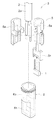
回転検出センサAは、図1に示すように、車軸B1と同軸に固定された着磁ロータB2の側端面に対向して固定される。着磁ロータB2は、その側端面が周方向に沿ってN極とS極とに交互に着磁されている。着磁ロータB2が車軸B1共に回転することによって生じる磁束の変化を回転検出センサAが検出することにより、車軸B1の回転速度すなわち車両の走行速度を検出することができる。
As shown in FIG. 1, the rotation detection sensor A is fixed to face the side end surface of the magnetized rotor B2 fixed coaxially with the axle B1. The side surface of the magnetized rotor B2 is alternately magnetized into N and S poles along the circumferential direction. By magnetizing the rotor B2 is detected by the rotation detecting sensor A of the change in magnetic flux caused by the rotation of both axles B1, it is possible to detect the running speed of the rotational speed, or the
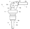
回転検出センサAは、図2〜図6に示すように、センサ素子(ホールIC)1と、センサ素子1に電気的に接続されたケーブル2とが設けられた組み立て式のセンサ本体3を有し、プラスチック等の樹脂で一体に型成形されたモールド成形部4にインサート成形されている。
As shown in FIGS. 2 to 6, the rotation detection sensor A has an assembly-
センサ本体3は、図2に示すように、センサ素子1が組み付けられたホルダ5と、ホルダ5が内装されたケース6とを備える。
ホルダ5は上下方向に長い棒状に形成され、ケーブル2を把持する一対のケーブル把持部5aを上端側に有し、センサ素子1を保持するセンサ保持部5bを下端側に有する。
ケース6は、上部に開口を有する円筒部6aと、円筒部6aの下部に連設された箱状のセンサ素子収容部6bとを備えている。
ホルダ5は、センサ保持部5bをセンサ素子収容部6bに挿入することにより、ケース6に内装してある。
As shown in FIG. 2, the sensor
The
The
The
モールド成形部4は、ケーブル2のセンサ本体3からの延出部分をセンサ本体3の一部と共に被覆する樹脂製被覆部4a(以下、「被覆部4a」という。)と、車両側に固定するためのボルト固定部4cを設けてある固定支持部4bとを一体に備える。
The molded
ケーブル2のセンサ本体3からの延出部分は、センサ本体3のホルダ5から延出された第1直線部分2aに対してL字状に屈曲された第2直線部分2bを形成する屈曲部7を有している。
したがって、被覆部4aは、センサ本体3の一部および屈曲部7を樹脂で一体に被覆するように型成形してある。
The extending portion of the
Therefore, the covering
図3,図4に示すように、センサ本体3のうちの被覆部4aが形成されない部位、具体的には、センサ素子収容部6bの下部側面には、被覆部4aの型成形の際にセンサ本体3の位置ずれを防止するために用いる突起状の係合部8が予め形成されている。
As shown in FIG. 3 and FIG. 4, a portion of the sensor
屈曲部7のケーブル長手方向に沿う前後に亘って、第1直線部分2aおよび第2直線部分2bのケーブル中心線Xを含む仮想の平面(図5,図6参照 以下、仮想平面という。)Zが厚さ方向の中心に位置する状態で、二つの補強リブ9a,9bを被覆部4aと一体に形成してある。
一方の補強リブ9aは、屈曲部7の内周縁に沿って形成してあり、他方の補強リブ9bは、屈曲部7の外周縁に沿って形成してある。
An imaginary plane including the cable center line X of the first
One reinforcing
本実施形態の回転検出センサAは、センサ本体3をインサート成形してある被覆部4aを固定支持部4bと共に一回の型成形で形成してある。
このため、センサ本体3と固定支持部4bとの相対位置を精度良く設定することができ、その結果、センサ素子1を検出対象に対して精度良く組み付けて検出精度を高めることができる。
In the rotation detection sensor A of the present embodiment, the covering
For this reason, the relative position between the sensor
図7〜図11は、センサ本体3の一部および屈曲部7をインサート成形してある被覆部4aを固定支持部4bと共に型成形するために使用する本発明による射出成形用の樹脂成形型Cを示す。
7 to 11 show a resin molding die C for injection molding according to the present invention which is used for molding a covering
樹脂成形型Cは、図7〜図9に示すように、ケース(センサ本体3の先端側部位に相当する。)6を嵌め込み固定する第1成形型C1と、ホルダ5のケース6から突出している部分(センサ本体3の基端側部位に相当する。)及びケーブル2を内包する第2成形型C2および第3成形型C3と、互いに型締めした第2成形型C2および第3成形型C3に対して型締めされて、ケーブル2の屈曲部7を形成する第4成形型C4とを備えている。
As shown in FIGS. 7 to 9, the resin molding die C protrudes from the first molding die C <b> 1 for fitting and fixing the case (corresponding to the tip side portion of the sensor body 3) 6 and the
第1成形型C1は、図7に示すように、円筒部6aの外周部を環状に囲む第1キャビティ11を形成し、円筒部6aの下部およびセンサ素子収容部6bを上下方向に沿わせて挿入するケース保持孔10が第1キャビティ11の底部に開口している。
As shown in FIG. 7, the first mold C1 forms a
ケース保持孔10のうちの第1キャビティ11の底部に開口する部分に、円筒部6aの底部を位置決め状態で嵌合保持する嵌合部14を形成してある。
円筒部6aの底部を嵌合部14に嵌合保持することにより、ケーブル2が組み付けられたセンサ本体3の先端側部位が第1成形型C1に嵌め込み固定される。
センサ素子収容部6bは、一側面がケース保持孔10の内面に接し、かつ、係合部8が設けられた側の側面との間に隙間15が形成される状態で、ケース保持孔10に挿入されている。
A
By fitting and holding the bottom portion of the
The sensor
第1成形型C1は、係合部8に対してケース保持孔10からの抜け出し方向下手側から係脱可能な棒状の係合部材16をケース保持孔10に対して出退自在に保持している。
係合部材16は、図示しない付勢部材で先端部がケース保持孔10から引退するように付勢され、センサ本体3の先端側部位が第1成形型C1に嵌め込み固定される際に、例えばエアシリンダの伸張又は収縮作動により付勢力に抗してケース保持孔10に突入し、係合部8との間に僅かな隙間を有する係合可能な状態に保持される。
The first molding die C1 holds a rod-
The engaging
なお、係合部材16は、例えばカム機構などを利用することにより、第2〜第4成形型C2,C3,C4のいずれかの型締め側への移動に伴って、先端部がケース保持孔10に突入して係合部8に係合するように連係してあってもよい。
Note that the
第2成形型C2および第3成形型C3は、図7,図8に示すように、ホルダ5のうちの円筒部6aから突出している部分およびホルダ5から延出するケーブル部分の外周部を環状に囲む第2キャビティ12を形成するように、互いに型締め・分離可能で、かつ、第1成形型C1に対して型締め可能に設けてある。
このため、第2成形型C2は、ケーブル2に対してケーブル屈曲方向の下手側から近接移動自在に支持され、第3成形型C3は、ケーブル2に対してケーブル屈曲方向の上手側から近接移動自在に支持されている。
As shown in FIGS. 7 and 8, the second mold C2 and the third mold C3 have an annular outer periphery of the
Therefore, the second molding die C2 is supported so as to be able to move closer to the
第2成形型C2および第3成形型C3は、ケーブル2のうち、センサ本体3から延出した部位を直線状に保持する第1保持部17を備えている。
第1保持部17は、第2成形型C2に一体に設けた第1支持部17aと、第3成形型C3に一体に設けた第2支持部17bとで構成してある。
The 2nd shaping | molding die C2 and the 3rd shaping | molding die C3 are provided with the 1st holding |
The 1st holding |
第1支持部17aは、第2成形型C2がケーブル2に対してケーブル屈曲方向の下手側から近接移動するに伴って、ケーブル2をケーブル屈曲方向の下手側から支持する。
第2支持部17bは、第3成形型C3がケーブル2に対してケーブル屈曲方向の上手側から近接移動するに伴って、ケーブル2をケーブル屈曲方向の上手側から支持する。
第1支持部17aおよび第2支持部17bの夫々は、図10に示すように、ケーブル2の外周面に当接する二つの当接部18をケーブル周方向に間隔を隔てて備えている。
二つの当接部18は、仮想平面Zを挟む両側でケーブル外周面に当接するように配置してある。
The
The
As shown in FIG. 10, each of the
The two
第3成形型C3は、ケーブル2のうち第1保持部17で保持された部位よりも延出した側で屈曲部7を形成すべく、ケーブル2に曲げ力を加えつつ保持する第2保持部19を備えている。
第2保持部19は、第3成形型C3がケーブル2に対してケーブル屈曲方向の上手側から近接移動するに伴って、ケーブル2をケーブル屈曲方向の下手側に向けて押し曲げた状態に保持する。
The 3rd shaping | molding die C3 is the 2nd holding | maintenance part hold | maintained applying a bending force to the
The
第2保持部19は、図11に示すように、ケーブル2の外周面を押圧する二つの当接部20をケーブル周方向に間隔を隔てて備えている。
二つの当接部20は、上側補強リブ9bを挟む両側、つまり、仮想平面Zを挟む両側でケーブル外周面に当接して押圧するように配置してある。
As shown in FIG. 11, the 2nd holding |
The two
第4成形型C4は、図8,図9に示すように、互いに型締めした第2成形型C2および第3成形型C3に対して下向きに近接移動させることにより、第2成形型C2および第3成形型C3と共にケーブル2の外周部に樹脂を充填する第3キャビティ13を形成し、第2成形型C2と共にケーブル2のうち屈曲部7から更に延出した部位を挟持する。
As shown in FIG. 8 and FIG. 9, the fourth mold C4 is moved downwardly toward the second mold C2 and the third mold C3 clamped to each other, thereby moving the second mold C2 and the second mold C4. A
第4成形型C4は、ケーブル2のうちの第2保持部19で保持された部位よりも更に延出した側でケーブル2に曲げ力を付与する第3保持部21を備えている。
第3保持部21は、第2保持部19で押し曲げられたケーブル2を第2成形型C2に向けて更に押圧することにより屈曲部7を形成する。
The 4th shaping | molding die C4 is provided with the 3rd holding |
The
第3保持部21は、ケーブル2の外周面に当接して押圧する二つの当接部22をケーブル周方向に間隔を隔てて備えている。
二つの当接部22は、上側補強リブ9bの形成予定箇所よりもケーブル長手方向に離れた位置において、図11に示すように、仮想平面Zを挟む両側でケーブル外周面に当接するように配置してある。
そして、図9に示すように、互いに連通するように形成された第1〜第3キャビティ11,12,13に溶融樹脂を射出することにより、センサ本体3の一部および屈曲部7をインサート成形してある被覆部4aを固定支持部4bと共に型成形することができる。
The
The two abutting
Then, as shown in FIG. 9, by injecting molten resin into the first to
したがって、第1保持部17,第2保持部19及び第3保持部21の夫々は、各当接部18,20,22が、ケーブル2のうちの仮想平面Zが交差する位置を除く位置に当接するよう構成されている。
このため、図1,図3〜図6に示すように、被覆部4aのうち、ケーブル2の延出方向に沿って屈曲部7を挟む両側の位置であって、仮想平面Zと交差する位置を除く位置に、型成形の際にケーブル2が保持された跡である凹部23が形成されている。
Therefore, each of the first holding
For this reason, as shown in FIGS. 1, 3 to 6, positions on both sides of the covering
本発明による回転検出センサは、各種回転装置における回転状態を検出するために利用することができる。 The rotation detection sensor according to the present invention can be used to detect the rotation state in various rotating devices.
1 センサ素子
2 ケーブル
3 センサ本体
4a 樹脂製被覆部
6 先端側部位(ケース)
7 屈曲部
8 係合部
11,12,13 キャビティ
16 係合部材
17 第1保持部
19 第2保持部
21 第3保持部
23 凹部
C1 第1成形型
C2 第2成形型
C3 第3成形型
C4 第4成形型
X 屈曲部のケーブル中心線
Z 屈曲部のケーブル中心線を含む平面(仮想平面)
DESCRIPTION OF
7
Claims (3)
前記センサ本体の基端側部位を内包し、前記基端側部位および前記ケーブルの外周部に樹脂を充填するキャビティを形成するよう、互いに型締め・分離可能で共に前記第1成形型に型締め可能な第2成形型および第3成形型と、
互いに型締めした前記第2成形型および前記第3成形型に型締めされて、前記ケーブルの屈曲部を形成すると共に、前記第2成形型および前記第3成形型と共に前記キャビティを形成し、前記第2成形型と共に前記ケーブルのうち前記屈曲部から更に延出した部位を挟持する第4成形型とを備え、
前記第2成形型および前記第3成形型が、前記ケーブルのうち、前記センサ本体から延出した部位を直線状に保持する第1保持部を備えると共に、
前記第3成形型が、前記ケーブルのうち前記第1保持部で保持された部位よりも延出した側で前記屈曲部を形成すべく前記ケーブルに曲げ力を加えつつ保持する第2保持部を備え、
前記第4成形型が、前記ケーブルのうち前記第2保持部で保持された部位よりも更に延出した側で前記ケーブルに曲げ力を付与する第3保持部を備えている樹脂成形型。 A first mold for fitting and fixing a front end portion of an assembly-type sensor body provided with a sensor element and a cable electrically connected to the sensor element;
The first mold is clamped and separable so as to form a cavity filled with resin in the base end side portion of the sensor body and in the base end side portion and the outer peripheral portion of the cable. Possible second mold and third mold;
The second mold and the third mold that are clamped together are clamped to form a bent portion of the cable, and the cavity is formed together with the second mold and the third mold, A fourth mold that clamps a portion of the cable that extends further from the bent portion together with the second mold ;
The second molding die and the third molding die include a first holding portion that linearly holds a portion of the cable that extends from the sensor body,
A second holding portion that holds the cable while applying a bending force to form the bent portion on a side of the cable that extends from a portion of the cable held by the first holding portion; Prepared,
The resin molding die provided with the 3rd holding part which gives a bending force to the cable in the side where the 4th forming mold extended further than the part held by the 2nd holding part among the cables .
Priority Applications (3)
| Application Number | Priority Date | Filing Date | Title |
|---|---|---|---|
| JP2014059694A JP6287420B2 (en) | 2014-03-24 | 2014-03-24 | Rotation detection sensor and its resin mold |
| US15/117,932 US10209094B2 (en) | 2014-03-24 | 2014-10-16 | Rotation detection sensor and resin molding die for the sensor |
| PCT/JP2014/077577 WO2015145841A1 (en) | 2014-03-24 | 2014-10-16 | Rotation detection sensor and resin molding die for same |
Applications Claiming Priority (1)
| Application Number | Priority Date | Filing Date | Title |
|---|---|---|---|
| JP2014059694A JP6287420B2 (en) | 2014-03-24 | 2014-03-24 | Rotation detection sensor and its resin mold |
Publications (3)
| Publication Number | Publication Date |
|---|---|
| JP2015184094A JP2015184094A (en) | 2015-10-22 |
| JP2015184094A5 JP2015184094A5 (en) | 2016-09-08 |
| JP6287420B2 true JP6287420B2 (en) | 2018-03-07 |
Family
ID=54194413
Family Applications (1)
| Application Number | Title | Priority Date | Filing Date |
|---|---|---|---|
| JP2014059694A Active JP6287420B2 (en) | 2014-03-24 | 2014-03-24 | Rotation detection sensor and its resin mold |
Country Status (3)
| Country | Link |
|---|---|
| US (1) | US10209094B2 (en) |
| JP (1) | JP6287420B2 (en) |
| WO (1) | WO2015145841A1 (en) |
Cited By (1)
| Publication number | Priority date | Publication date | Assignee | Title |
|---|---|---|---|---|
| EP3730273A1 (en) * | 2019-04-24 | 2020-10-28 | TE Connectivity Germany GmbH | Injection mold for overmolding inserts in a workpiece and injection-molded workpiece having an insert |
Families Citing this family (8)
| Publication number | Priority date | Publication date | Assignee | Title |
|---|---|---|---|---|
| JP6270043B2 (en) * | 2014-07-11 | 2018-01-31 | 株式会社デンソー | Rotation detector |
| JP6135612B2 (en) * | 2014-07-11 | 2017-05-31 | 株式会社デンソー | Rotation detection device and method of manufacturing rotation detection device |
| JP6679470B2 (en) * | 2016-12-05 | 2020-04-15 | 株式会社東海理化電機製作所 | Mold device, insert molded article manufacturing method, and insert molded article |
| CN206698545U (en) * | 2017-03-31 | 2017-12-01 | 泰科电子(上海)有限公司 | Electronic component support frame, electronic element assembly and electric appliance component |
| DE102017007399A1 (en) * | 2017-08-04 | 2019-02-07 | Wabco Gmbh | Speed sensor for a vehicle, in particular a commercial vehicle, and a method for its production |
| JP7106947B2 (en) * | 2018-04-03 | 2022-07-27 | 株式会社デンソー | Position detector |
| CN109531919B (en) * | 2018-12-29 | 2020-12-29 | 上海超日精密模具有限公司 | Injection molding method and injection mold for motor shell with metal insert |
| US20210172208A1 (en) * | 2019-12-04 | 2021-06-10 | Kiekert Ag | Sensor lever for technical applications in motor vehicles |
Family Cites Families (8)
| Publication number | Priority date | Publication date | Assignee | Title |
|---|---|---|---|---|
| JPS5462088U (en) * | 1977-10-12 | 1979-05-01 | ||
| JPS5970527A (en) * | 1982-10-16 | 1984-04-21 | Oiles Ind Co Ltd | Preparation of cable guide pipe equipped with curved part |
| JP2000097955A (en) * | 1998-09-22 | 2000-04-07 | Honda Lock Mfg Co Ltd | Sensor device |
| DE19857880B4 (en) | 1997-12-18 | 2008-07-31 | Honda Lock Mfg. Co., Ltd. | sensor |
| JPH11325961A (en) * | 1998-05-19 | 1999-11-26 | Toyo Denso Co Ltd | Sensor body for rotation detector |
| JP4487851B2 (en) * | 2005-05-20 | 2010-06-23 | 株式会社デンソー | Method for manufacturing vehicle rotation detection device |
| DE102007060604A1 (en) * | 2007-12-13 | 2009-06-18 | Continental Teves Ag & Co. Ohg | Magnetic field sensor element |
| JP2015100917A (en) * | 2013-11-20 | 2015-06-04 | トヨタ自動車株式会社 | Insert molded article, mold for insert molded article, and method for manufacturing insert molded article |
-
2014
- 2014-03-24 JP JP2014059694A patent/JP6287420B2/en active Active
- 2014-10-16 US US15/117,932 patent/US10209094B2/en active Active
- 2014-10-16 WO PCT/JP2014/077577 patent/WO2015145841A1/en active Application Filing
Cited By (1)
| Publication number | Priority date | Publication date | Assignee | Title |
|---|---|---|---|---|
| EP3730273A1 (en) * | 2019-04-24 | 2020-10-28 | TE Connectivity Germany GmbH | Injection mold for overmolding inserts in a workpiece and injection-molded workpiece having an insert |
Also Published As
| Publication number | Publication date |
|---|---|
| JP2015184094A (en) | 2015-10-22 |
| WO2015145841A1 (en) | 2015-10-01 |
| US10209094B2 (en) | 2019-02-19 |
| US20160356627A1 (en) | 2016-12-08 |
Similar Documents
| Publication | Publication Date | Title |
|---|---|---|
| JP6287420B2 (en) | Rotation detection sensor and its resin mold | |
| JP2015184094A5 (en) | ||
| JP4487851B2 (en) | Method for manufacturing vehicle rotation detection device | |
| JP5655826B2 (en) | Rotation detecting device and manufacturing method thereof | |
| US9523592B2 (en) | Rotation detector | |
| JP2005227095A (en) | Magnetic variable sensor | |
| JP6108292B2 (en) | Wheel speed sensor | |
| KR101068233B1 (en) | Electronically controlled actuator for limited slip differential | |
| JP6015008B2 (en) | Sensor | |
| JP2013148556A5 (en) | ||
| WO2014103469A1 (en) | Wheel speed sensor and wheel speed sensor manufacturing method | |
| KR20150093008A (en) | A assembly of wheel speed sensor | |
| JP6715110B2 (en) | Stroke sensor and saddle type vehicle | |
| US20180202836A1 (en) | Position sensor | |
| CN103847065B (en) | Insert molded article, insert molding method, and insert molding apparatus | |
| JP2017111002A (en) | Rotation detection device | |
| WO2018079231A1 (en) | Male connector | |
| JP6354528B2 (en) | Manufacturing method of physical quantity measuring sensor | |
| JP7472739B2 (en) | Wire Harness | |
| JP6455207B2 (en) | Cable with resin molded body and manufacturing method thereof | |
| JP2934910B2 (en) | Method of manufacturing probe for brake pad wear detection device | |
| ITTO20010246A1 (en) | ELECTRIC CONNECTOR FOR THE VEHICLE STEERING WHEEL. | |
| US9561608B2 (en) | Sensor unit | |
| CN106574936A (en) | Carrier for a sensor element, component group, and rotational speed sensor | |
| JP2016068843A (en) | Fixing structure of grip heater |
Legal Events
| Date | Code | Title | Description |
|---|---|---|---|
| A521 | Request for written amendment filed |
Free format text: JAPANESE INTERMEDIATE CODE: A523 Effective date: 20160722 |
|
| A621 | Written request for application examination |
Free format text: JAPANESE INTERMEDIATE CODE: A621 Effective date: 20161128 |
|
| A131 | Notification of reasons for refusal |
Free format text: JAPANESE INTERMEDIATE CODE: A131 Effective date: 20171121 |
|
| A521 | Request for written amendment filed |
Free format text: JAPANESE INTERMEDIATE CODE: A523 Effective date: 20171221 |
|
| TRDD | Decision of grant or rejection written | ||
| A01 | Written decision to grant a patent or to grant a registration (utility model) |
Free format text: JAPANESE INTERMEDIATE CODE: A01 Effective date: 20180109 |
|
| A61 | First payment of annual fees (during grant procedure) |
Free format text: JAPANESE INTERMEDIATE CODE: A61 Effective date: 20180122 |
|
| R151 | Written notification of patent or utility model registration |
Ref document number: 6287420 Country of ref document: JP Free format text: JAPANESE INTERMEDIATE CODE: R151 |